EP4444053A1 - Inverter assembly - Google Patents
Inverter assembly Download PDFInfo
- Publication number
- EP4444053A1 EP4444053A1 EP23180962.5A EP23180962A EP4444053A1 EP 4444053 A1 EP4444053 A1 EP 4444053A1 EP 23180962 A EP23180962 A EP 23180962A EP 4444053 A1 EP4444053 A1 EP 4444053A1
- Authority
- EP
- European Patent Office
- Prior art keywords
- contact terminal
- abutting
- output
- output portion
- copper busbar
- Prior art date
- Legal status (The legal status is an assumption and is not a legal conclusion. Google has not performed a legal analysis and makes no representation as to the accuracy of the status listed.)
- Pending
Links
- 229910052802 copper Inorganic materials 0.000 claims abstract description 129
- 239000010949 copper Substances 0.000 claims abstract description 129
- RYGMFSIKBFXOCR-UHFFFAOYSA-N Copper Chemical compound [Cu] RYGMFSIKBFXOCR-UHFFFAOYSA-N 0.000 claims abstract description 123
- 230000004308 accommodation Effects 0.000 claims abstract description 33
- 238000003032 molecular docking Methods 0.000 claims description 36
- 238000006073 displacement reaction Methods 0.000 claims description 23
- 238000009434 installation Methods 0.000 claims description 18
- 125000006850 spacer group Chemical group 0.000 claims description 11
- 239000000463 material Substances 0.000 claims description 9
- 239000007769 metal material Substances 0.000 claims description 6
- 239000012774 insulation material Substances 0.000 claims description 4
- 230000002452 interceptive effect Effects 0.000 claims description 4
- 230000017525 heat dissipation Effects 0.000 description 4
- 230000009286 beneficial effect Effects 0.000 description 3
- 238000009413 insulation Methods 0.000 description 3
- 230000006835 compression Effects 0.000 description 2
- 238000007906 compression Methods 0.000 description 2
- 230000015572 biosynthetic process Effects 0.000 description 1
- 230000000694 effects Effects 0.000 description 1
- 230000002349 favourable effect Effects 0.000 description 1
- 238000004519 manufacturing process Methods 0.000 description 1
Images






Classifications
-
- H—ELECTRICITY
- H05—ELECTRIC TECHNIQUES NOT OTHERWISE PROVIDED FOR
- H05K—PRINTED CIRCUITS; CASINGS OR CONSTRUCTIONAL DETAILS OF ELECTRIC APPARATUS; MANUFACTURE OF ASSEMBLAGES OF ELECTRICAL COMPONENTS
- H05K7/00—Constructional details common to different types of electric apparatus
- H05K7/14—Mounting supporting structure in casing or on frame or rack
- H05K7/1422—Printed circuit boards receptacles, e.g. stacked structures, electronic circuit modules or box like frames
- H05K7/1427—Housings
- H05K7/1432—Housings specially adapted for power drive units or power converters
- H05K7/14329—Housings specially adapted for power drive units or power converters specially adapted for the configuration of power bus bars
-
- H—ELECTRICITY
- H02—GENERATION; CONVERSION OR DISTRIBUTION OF ELECTRIC POWER
- H02M—APPARATUS FOR CONVERSION BETWEEN AC AND AC, BETWEEN AC AND DC, OR BETWEEN DC AND DC, AND FOR USE WITH MAINS OR SIMILAR POWER SUPPLY SYSTEMS; CONVERSION OF DC OR AC INPUT POWER INTO SURGE OUTPUT POWER; CONTROL OR REGULATION THEREOF
- H02M7/00—Conversion of AC power input into DC power output; Conversion of DC power input into AC power output
- H02M7/003—Constructional details, e.g. physical layout, assembly, wiring or busbar connections
-
- H—ELECTRICITY
- H01—ELECTRIC ELEMENTS
- H01R—ELECTRICALLY-CONDUCTIVE CONNECTIONS; STRUCTURAL ASSOCIATIONS OF A PLURALITY OF MUTUALLY-INSULATED ELECTRICAL CONNECTING ELEMENTS; COUPLING DEVICES; CURRENT COLLECTORS
- H01R13/00—Details of coupling devices of the kinds covered by groups H01R12/70 or H01R24/00 - H01R33/00
- H01R13/02—Contact members
- H01R13/22—Contacts for co-operating by abutting
- H01R13/24—Contacts for co-operating by abutting resilient; resiliently-mounted
- H01R13/2407—Contacts for co-operating by abutting resilient; resiliently-mounted characterized by the resilient means
- H01R13/2428—Contacts for co-operating by abutting resilient; resiliently-mounted characterized by the resilient means using meander springs
-
- H—ELECTRICITY
- H01—ELECTRIC ELEMENTS
- H01R—ELECTRICALLY-CONDUCTIVE CONNECTIONS; STRUCTURAL ASSOCIATIONS OF A PLURALITY OF MUTUALLY-INSULATED ELECTRICAL CONNECTING ELEMENTS; COUPLING DEVICES; CURRENT COLLECTORS
- H01R13/00—Details of coupling devices of the kinds covered by groups H01R12/70 or H01R24/00 - H01R33/00
- H01R13/02—Contact members
- H01R13/22—Contacts for co-operating by abutting
- H01R13/24—Contacts for co-operating by abutting resilient; resiliently-mounted
- H01R13/2407—Contacts for co-operating by abutting resilient; resiliently-mounted characterized by the resilient means
- H01R13/2414—Contacts for co-operating by abutting resilient; resiliently-mounted characterized by the resilient means conductive elastomers
-
- H—ELECTRICITY
- H01—ELECTRIC ELEMENTS
- H01R—ELECTRICALLY-CONDUCTIVE CONNECTIONS; STRUCTURAL ASSOCIATIONS OF A PLURALITY OF MUTUALLY-INSULATED ELECTRICAL CONNECTING ELEMENTS; COUPLING DEVICES; CURRENT COLLECTORS
- H01R25/00—Coupling parts adapted for simultaneous co-operation with two or more identical counterparts, e.g. for distributing energy to two or more circuits
- H01R25/14—Rails or bus-bars constructed so that the counterparts can be connected thereto at any point along their length
- H01R25/142—Their counterparts
-
- H—ELECTRICITY
- H01—ELECTRIC ELEMENTS
- H01R—ELECTRICALLY-CONDUCTIVE CONNECTIONS; STRUCTURAL ASSOCIATIONS OF A PLURALITY OF MUTUALLY-INSULATED ELECTRICAL CONNECTING ELEMENTS; COUPLING DEVICES; CURRENT COLLECTORS
- H01R25/00—Coupling parts adapted for simultaneous co-operation with two or more identical counterparts, e.g. for distributing energy to two or more circuits
- H01R25/14—Rails or bus-bars constructed so that the counterparts can be connected thereto at any point along their length
- H01R25/145—Details, e.g. end pieces or joints
-
- H—ELECTRICITY
- H02—GENERATION; CONVERSION OR DISTRIBUTION OF ELECTRIC POWER
- H02M—APPARATUS FOR CONVERSION BETWEEN AC AND AC, BETWEEN AC AND DC, OR BETWEEN DC AND DC, AND FOR USE WITH MAINS OR SIMILAR POWER SUPPLY SYSTEMS; CONVERSION OF DC OR AC INPUT POWER INTO SURGE OUTPUT POWER; CONTROL OR REGULATION THEREOF
- H02M1/00—Details of apparatus for conversion
-
- H—ELECTRICITY
- H02—GENERATION; CONVERSION OR DISTRIBUTION OF ELECTRIC POWER
- H02M—APPARATUS FOR CONVERSION BETWEEN AC AND AC, BETWEEN AC AND DC, OR BETWEEN DC AND DC, AND FOR USE WITH MAINS OR SIMILAR POWER SUPPLY SYSTEMS; CONVERSION OF DC OR AC INPUT POWER INTO SURGE OUTPUT POWER; CONTROL OR REGULATION THEREOF
- H02M7/00—Conversion of AC power input into DC power output; Conversion of DC power input into AC power output
- H02M7/42—Conversion of DC power input into AC power output without possibility of reversal
- H02M7/54—Conversion of DC power input into AC power output without possibility of reversal by dynamic converters
- H02M7/58—Conversion of DC power input into AC power output without possibility of reversal by dynamic converters using mechanical contact-making and -breaking parts to interrupt a single potential
-
- H—ELECTRICITY
- H01—ELECTRIC ELEMENTS
- H01R—ELECTRICALLY-CONDUCTIVE CONNECTIONS; STRUCTURAL ASSOCIATIONS OF A PLURALITY OF MUTUALLY-INSULATED ELECTRICAL CONNECTING ELEMENTS; COUPLING DEVICES; CURRENT COLLECTORS
- H01R13/00—Details of coupling devices of the kinds covered by groups H01R12/70 or H01R24/00 - H01R33/00
- H01R13/02—Contact members
- H01R13/22—Contacts for co-operating by abutting
- H01R13/24—Contacts for co-operating by abutting resilient; resiliently-mounted
- H01R13/2407—Contacts for co-operating by abutting resilient; resiliently-mounted characterized by the resilient means
- H01R13/2421—Contacts for co-operating by abutting resilient; resiliently-mounted characterized by the resilient means using coil springs
-
- H—ELECTRICITY
- H01—ELECTRIC ELEMENTS
- H01R—ELECTRICALLY-CONDUCTIVE CONNECTIONS; STRUCTURAL ASSOCIATIONS OF A PLURALITY OF MUTUALLY-INSULATED ELECTRICAL CONNECTING ELEMENTS; COUPLING DEVICES; CURRENT COLLECTORS
- H01R2105/00—Three poles
-
- H—ELECTRICITY
- H01—ELECTRIC ELEMENTS
- H01R—ELECTRICALLY-CONDUCTIVE CONNECTIONS; STRUCTURAL ASSOCIATIONS OF A PLURALITY OF MUTUALLY-INSULATED ELECTRICAL CONNECTING ELEMENTS; COUPLING DEVICES; CURRENT COLLECTORS
- H01R25/00—Coupling parts adapted for simultaneous co-operation with two or more identical counterparts, e.g. for distributing energy to two or more circuits
- H01R25/16—Rails or bus-bars provided with a plurality of discrete connecting locations for counterparts
- H01R25/161—Details
- H01R25/162—Electrical connections between or with rails or bus-bars
-
- H—ELECTRICITY
- H01—ELECTRIC ELEMENTS
- H01R—ELECTRICALLY-CONDUCTIVE CONNECTIONS; STRUCTURAL ASSOCIATIONS OF A PLURALITY OF MUTUALLY-INSULATED ELECTRICAL CONNECTING ELEMENTS; COUPLING DEVICES; CURRENT COLLECTORS
- H01R4/00—Electrically-conductive connections between two or more conductive members in direct contact, i.e. touching one another; Means for effecting or maintaining such contact; Electrically-conductive connections having two or more spaced connecting locations for conductors and using contact members penetrating insulation
- H01R4/28—Clamped connections, spring connections
- H01R4/48—Clamped connections, spring connections utilising a spring, clip, or other resilient member
- H01R4/4854—Clamped connections, spring connections utilising a spring, clip, or other resilient member using a wire spring
- H01R4/4863—Coil spring
Definitions
- the present disclosure relates to an electronic assembly structure, and more particularly to an inverter assembly having an elastic component for abutting against the output copper busbar and the contact terminal of the load and forming the contact therewith, so as to reduce the assembling cost of the inverter assembly sufficiently, and avoid the problem of poor contact caused by the vibration during use at the same time.
- an electronic device is often combined with a heat dissipation assembly to dissipate the internal heat.
- a high-efficiency power module used in the inverter is often accompanied with a lot of heat generated therefrom, the inverter assembly must be combined with a water-cooled heat dissipation module to achieve an effective effect of heat dissipation. Therefore, the high-power module is combined with the water-cooled heat dissipation module to form a heavy assembled structure.
- an AC output terminal of the assembled structure of the inverter needs to be electrically connected to an AC input end of the motor.
- the AC output copper busbar of the conventional inverter needs to be connected to the AC input copper busbar of the motor through the screw or the rivet.
- the AC output copper busbar of the inverter must be aligned with the screw holes or rivet holes on the AC input copper busbar of the motor. Therefore, it is necessary to precisely control the dimensional tolerance of the copper busbars and the assembling tolerances of the inverter and the motor. Moreover, the cost of manufacturing or assembling is also increased.
- the dimensional tolerances may cause the stress problems, and it may cause the structural damage of the copper busbars. Furthermore, the poor contact may be caused due to the vibration and loosening during use.
- An object of the present disclosure is to provide an inverter assembly having an elastic component for abutting against the output copper busbar and the contact terminal and forming the contact therewith, so as to reduce the assembling cost of the inverter assembly sufficiently, and avoid the problem of poor contact caused by the vibration during use.
- the elastic component is stressed to provide a restoring force, which is used to push the output copper busbar abutting against the contact terminal to achieve the electrical connection between the output copper busbar and the contact terminal.
- the elastic component is not directly in contact with the contact terminal. Therefore, for the design of the elastic component, there is no need to consider the electrical impedance, and it makes the structure and the material design of the elastic component less restrictive, and is also beneficial to the insulation design.
- Another object of the present disclosure is to provide an inverter assembly.
- An output copper busbar and a contact terminal are electrically connected through the docking action to implement the DC electrical connection between the battery and the inverter or the AC electrical connection between the inverter and the load. There is no need to use the screwdriver and other tools to achieve the mutual electrical connection.
- the output copper busbar and the contact terminal abut against each other through the modular elastic components, it facilitates to avoid the poor contact between the output copper busbar and the contact terminal due to the assembly tolerances during the docking action thereof.
- the modular elastic component Since the modular elastic component has an assembling position matched to the corresponding positions of the output copper busbar and the contact terminal, and the docking action of the inverter assembly, it helps to simplify the structural design of the elastic component, reduce the assembling cost, and improve the module commonality of elastic components. Moreover, the elastic components are arranged under the output copper busbars, and the docking action between the output copper busbars and the contact terminals is not affected by the elastic components. On the other hands, it allows to arrange a pair of spacer columns on the elastic components to correspond to the output portion of the output copper busbar, so as to simplify the alignment requirements during assembling.
- the restoring force provided by stressing the elastic components abuts against the output portion of the output copper busbar towards the contact terminal, so as to ensure that the output portion of the output copper busbar and the contact terminals of the load are abutted against each other and maintained the contact therebetween.
- the impact of stress due to vibration won't influence the contact between the output copper busbar and the contact terminal of the inverter assembly.
- the restoring force produced by the compression of the elastic components is sufficient to maintain the continuous and stable contact between the output portion of the output copper busbar and the contact terminal.
- the displacement distance of the contact terminal sliding relative to the output portion of the output copper busbar can be set when the inverter assembly is docked with the battery or the load, the restoring force generated by the output portion of the output copper busbar pushing against the elastic component can be controlled and adjusted within a specific range, so that the electrical contact between the output portion of the output copper busbar and the contact terminal is maintained stably, and the application of modular electrical connection is achieved.
- an inverter assembly includes a base, a contact terminal, an output copper busbar and an elastic component.
- the output copper busbar is disposed on the base, wherein the output copper busbar includes an output portion spatially corresponding to the base and configured to form an electrical connection with the contact terminal.
- the elastic component is disposed on the base and includes an abutting element, an elastic element and an accommodation seat, wherein the accommodation seat is disposed on the base, the abutting element is connected to the accommodation seat through the elastic element along an axial direction, the elastic element provides a restoring force when the abutting element is stressed along the axial direction, and the abutting element is spatially corresponding to the output portion, wherein when the base is docked with the contact terminal, the abutting element of the elastic component abuts against the output portion to attach to the contact terminal, and the contact terminal abuts against the abutting element and the elastic element through the output portion, so that the restoring force provided by the elastic element keeps the output portion abutting against the contact terminal.
- the output copper busbar is a DC output copper busbar connected to a power source
- the power source is a DC power generated by a battery
- the contact terminal is connected to an inverter module, wherein when the base is docked with the contact terminal, the abutting element of the elastic component abuts against the output portion to attach to the contact terminal, and the contact terminal abuts against the abutting element and the elastic element through the output portion, so that the restoring force provided by the elastic element keeps the output portion abutting against the contact terminal, and the power source provides the inverter module with the DC power through the output copper busbar.
- the contact terminal is connected to an power source, the power source is a DC power generated by a battery, the output copper busbar is connected to inverter module, and the output copper busbar is a DC output copper busbar, wherein when the base is docked with the contact terminal, the abutting element of the elastic component abuts against the output portion to attach to the contact terminal, and the contact terminal abuts against the abutting element and the elastic element through the output portion, so that the restoring force provided by the elastic element keeps the output portion abutting against the contact terminal, and the power source provides the inverter module with the DC power through the output copper busbar.
- the contact terminal is connected to an power source
- the power source is an AC power provided by an inverter module
- the output copper busbar is an AC output copper busbar and connected to a load
- the output copper busbar is an AC output copper busbar connected to a power source
- the power source is an AC power generated by an inverter module
- the contact terminal is connected to a load
- the abutting element of the elastic component abuts against the output portion to attach to the contact terminal
- the contact terminal abuts against the abutting element and the elastic element through the output portion, so that the restoring force provided by the elastic element keeps the output portion abutting against the contact terminal
- the inverter module provides the load with the AC power from the power source through the output copper busbar.
- the base includes an installation surface configured to dock with the load along a docking direction and attach to the contact terminal of the load
- the inverter module includes a power module disposed on the base and electrically connected to the output copper busbar, wherein when the base is docked with the contact terminal, the installation surface drives the elastic component and the output portion to attach to the contact terminal, the contact terminal abuts against the abutting element and the elastic element through the output portion, the abutting element is stressed along the axial direction, and the restoring force is provided by the elastic element to keeps the output portion abutting against the contact terminal, wherein when the contact terminal is not in contact with the output portion, the abutting element keeps interfering with the output portion.
- the elastic component includes 3N of the abutting elements, N is an integer, and N ⁇ 1.
- the output portion is at least partially overlapped with the abutting element and at least partially overlapped with the contact terminal in view of the docking direction.
- an area of the output portion is greater than an area of the abutting element, and greater than an area of the contact terminal in the view of the docking direction.
- the elastic component further includes a sleeve embedded in the accommodation seat, the sleeve includes a top opening, a bottom portion and a perforation, the perforation is disposed on the bottom portion and in communication with the top opening, the elastic element is accommodated in the sleeve through the top opening, and the elastic element is connected between the abutting element and the bottom portion.
- the abutting element is partially accommodated in the sleeve
- the elastic element is a telescopic spring accommodated in the sleeve through the top opening and connected between the abutting element and the bottom portion of the sleeve.
- the abutting element includes an abutting portion and a fitting portion, and an area of the abutting portion is greater than an area of the fitting portion in view of the docking direction.
- a top end of the fitting portion is connected to the abutting portion, a bottom end of the fitting portion passes through the perforation on the bottom portion of the sleeve, and the abutting element is allowed sliding relative to the sleeve in the docking direction and abutting against the elastic element so as to provide the restoring force.
- the elastic element is disposed around an outer periphery of the fitting portion and connected between the abutting portion and the bottom portion of the sleeve
- the fitting portion includes an engaged slot disposed at the bottom end of the fitting portion
- the elastic component further includes an engaging ring, wherein the bottom end of the fitting portion passes through the perforation on the bottom portion of the sleeve, and the engaging ring and the engaged slot are engaged with each other, so that the abutting element is limited and not detached from the sleeve.
- the elastic component further includes a pair of spacer columns disposed on the accommodation seat, spatially corresponding to the output portion, and arranged on two lateral sides of the sleeve, and a height of the pair of spacer columns relative to the accommodation seat is greater than a height of the abutting element maintained at an initial position relative to the accommodation seat, so as to form a height-difference distance, wherein the height-difference distance is less than a thickness of the output portion.
- a first width is formed between the pair of spacer columns, the output portion has a second width), and the first width is greater than the second width.
- the contact terminal when the base is docked with the load, the contact terminal is in contact with the output portion and moved toward the installation surface by a first displacement distance, and the contact terminal abuts against the abutting element through the output portion and drives the abutting element to move toward the installation surface by a second displacement distance, wherein the first displacement distance is greater than or equal to the second displacement distance.
- the output portion has a thickness in view of the docking direction, and the second displacement distance is greater than or equal to the thickness.
- the output copper busbar is made of a soft-copper material
- the accommodation seat is made of an insulation material
- the abutting element is made of a metal material, wherein a hardness of the metal material is greater than a hardness of the soft-copper material.
- first and second features are formed in direct contact
- additional features may be formed between the first and second features, such that the first and second features may not be in direct contact
- present disclosure may repeat reference numerals and/or letters in the various examples. This repetition is for the purpose of simplicity and clarity and does not in itself dictate a relationship between the various embodiments and/or configurations discussed.
- spatially relative terms such as “top,” “bottom,” “upper,” “lower” and the like, may be used herein for ease of description to describe one element or feature's relationship to another element(s) or feature(s) as illustrated in the figures.
- the spatially relative terms are intended to encompass different orientations of the device in use or operation in addition to the orientation depicted in the figures.
- the apparatus may be otherwise oriented (rotated 90 degrees or at other orientations) and the spatially relative descriptors used herein may likewise be interpreted accordingly.
- the present disclosure provides an inverter assembly 1 including a base 10, a contact terminal 90, an output copper busbar 30 and an elastic component 40.
- the output copper busbar 30 is disposed on the base 10.
- the output copper busbar 30 includes an output portion 31 spatially corresponding to the base 10 and configured to form an electrical connection with the contact terminal 90.
- the elastic component 40 is disposed on the base 10 and includes an abutting element 41, an elastic element 42 and an accommodation seat 43.
- the accommodation seat 43 is disposed on the base 10, the abutting element 41 is connected to the accommodation seat 43 through the elastic element 42 along an axial direction.
- the elastic element 42 provides a restoring force when the abutting element 41 is stressed along the axial direction, and the abutting element 41 is spatially corresponding to the output portion 31.
- the abutting element 41 of the elastic component 40 abuts against the output portion 31 to attach to the contact terminal 90, and the contact terminal 90 abuts against the abutting element 41 and the elastic element 42 through the output portion 31.
- the restoring force provided by the elastic element 42 keeps the output portion 31 abutting against the contact terminal 90.
- the electrical connection between the output copper busbar 30 and the contact terminal 90 is achieved, and a power source is outputted.
- the inverter assembly 1 of the present disclosure can be applied for DC output between the battery and the inverter module, or for AC output between the inverter module and a load 9.
- the power source can be for example but not limited to a DC power source generated by a battery.
- the output copper busbar 30 is a DC output copper busbar and connected to the power source.
- the contact terminal 90 is connected to an inverter module. When the base 10 is docked with the contact terminal 90, the abutting element 41 of the elastic component 40 abuts against the output portion 31 to attach to the contact terminal 90.
- the contact terminal 90 is pushed against the abutting element 41 and the elastic element 42 through the output portion 31, and the restoring force provide by the elastic element 42 keeps the output portion 31 in contact with the contact terminal 90.
- the DC power of the battery is served as the power source, and the DC power is supplied to the inverter module through the output copper busbar 30.
- the contact terminal 90 is connected to an inverter module, and the output copper busbar 30 is connected to the power source.
- the restoring force provided by the elastic element 42 keeps the output portion 31 in contact with the contact terminal 90.
- the DC power of the battery is served as the power source, and the DC power is supplied to the inverter module through the output copper busbar 30.
- the contact terminal 90 is connected to the power source, and the power source is an AC power provided by the inverter module.
- the output copper busbar 30 is an AC output copper busbar and connected to a load.
- the restoring force provided by the elastic element 42 keeps the output portion 31 in contact with the contact terminal 90.
- the AC power provided by the inverter module is served as the power source, and the AC power is supplied to the load through the output copper busbar 30.
- the output copper busbar 30 is an AC output copper busbar and connected to an AC power source, which is provided by an inverter module and served as a power source.
- the contact terminal 90 is connected to the load 9.
- the restoring force provided by the elastic element 42 keeps the output portion 31 in contact with the contact terminal 90.
- the AC power provided by the inverter module is served as the power source, and the AC power is supplied to the load through the output copper busbar 30.
- the power source can be for example but not limited to an AC power or a DC power, which is connected to the output copper busbar 30 and then transmitted to the contact terminal 90.
- the AC power or the DC power transmitted to the contact terminal 90 can be used by the load or the inverter module.
- the power source can be connected to the contact terminal 90.
- the AC power or the DC power is transmitted to the output copper busbar 30.
- the output copper busbar 30 outputs the AC power or the DC power to the load or the inverter module for use.
- the combination of the inverter module connected to the output copper busbar 30 and the load 9 connected to the contact terminal 90 for the AC power output is used in the following descriptions for illustration. The present disclosure is not limited thereto.
- the base 10 includes an installation surface 11, for example the upper surface of the base 10, configured to dock with the load 9 along a docking direction, such as the Z axial direction.
- the installation surface 11 is attached to the contact terminal 90 of the load 9.
- the inverter module includes a power module 20 disposed on the installation surface 11 of the base 10.
- the power module 20 is stacked on the upper surface and the lower surface of the base.
- the output copper busbar 30 is an AC output copper busbar including a connection portion 32 and electrically connected to the power module 20.
- the manner of disposing the output copper busbar 30 on the base or the electrical connection between the output copper busbar 30 and the power module 20 is adjustable according to the practical requirements, and not limited thereto in the present disclosure.
- the output copper busbar 30 includes the output portion 31 spatially corresponding to the installation surface 11.
- the elastic component 40 is disposed on the installation surface 11 of the base 10, and includes the abutting element 41, the elastic element 42 and the accommodation seat 43.
- the accommodation seat 43 is made of an insulation material and arranged on the installation surface 11 of the base 10.
- the abutting element 41 is connected to the accommodation seat 43 through the elastic element 42. Moreover, a restoring force is provided by the elastic element 42 when the abutting element 41 is forced toward the installation surface 11 in the axial direction.
- the abutting element 41 keeps interfering with the output portion 31.
- the abutting element 41 is spatially corresponding to the output portion 31 of the output copper busbar 30.
- the installation surface drives the elastic component 40 and the output portion 31 of the output copper busbar 30 to attach to the contact terminal 90, and the contact terminal 90 abuts against the abutting element 41 and the elastic element 42 downwardly through the output portion 31.
- the abutting element 41 is stressed along the axial direction, and the restoring force is provided by the elastic element 42 to keeps the output portion 31 of the output copper busbar 30 abutting against the contact terminal 90 of the load 9.
- the output copper busbar 30 of the inverter assembly 1 and the contact terminal 90 of the load 9 are electrically connected with each other through the docking action of the inverter assembly 1 and the load 9.
- the electrical connection between the output portion 31 of the output copper busbar 30 and the load 9 is achieved by utilizing the abutment of the elastic component 40, so as to reduce the assembling cost of the inverter assembly 1 and the load 9 sufficiently, and avoid the problem of poor contact caused by the vibration during use at the same time.
- the numbers of corresponding structures of the contact terminal 90 of the load 9, the output portion 31 of the output copper busbar 30 and the elastic component 40 are three as an example for illustrating that the inverter assembly 1 has a three-phase AC output, and the present disclosure is not limited thereto.
- the elastic component 40 includes 3N abutting elements 41, N is an integer, and N ⁇ 1, so that the elastic component 40 is allowed to correspond to one single-phase output application or a multiphase output application.
- the numbers of corresponding structures of the power module 20, the contact terminal 90 of the load 9, the output portion 31 of the output copper busbar 30 and the elastic component 40 are adjustable according to the practical requirements, and the present disclosure is not limited thereto.
- the output copper busbar 30 is made of a soft-copper material
- the abutting element 41 is made of a metal material.
- a hardness of the metal material is greater than a hardness of the soft-copper material.
- the elastic component 40 is stressed to provide the restoring force, and further used to push the output copper busbar 30 against the contact terminal 90 to achieve the electrical connection between the output copper busbar 30 and the contact terminal 90.
- the abutting element 41, the elastic element and the accommodation seat 43 of the elastic component 40 is not directly in contact with the contact terminal 90. Therefore, for the design of the elastic component 40, there is no need to consider the electrical impedance, and it makes the structure and the material design of the elastic component 40 less restrictive, and is also beneficial to the insulation design.
- the present disclosure is not limited thereto.
- the output portion 31 of the output copper busbar 30 is at least partially overlapped with the abutting element 41 of the elastic component 40 in view of the docking direction (i.e., the Z axial direction). Moreover, when the base 10 is docked with the load 9, the output portion 31, the abutting element 41 and the contact terminal 90 are at least partially overlapped with each other. In this way, the contact terminal 90 is driven to push against the lower abutting element 41 and the elastic element 42 through the output portion during the docking action of the inverter assembly 1 and the load 9.
- an area of the output portion 31 is greater than an area of the abutting element 41, and greater than an area of the contact terminal 90 in the view of the docking direction (i.e., the Z axial direction), and it also facilitates the restoring force of the elastic element 42 to act on the output portion 31, and avoids the poor contact between the output portion 31 and the contact terminal 90 caused by the assembly tolerances during docking the inverter assembly 1 and the load 9.
- the present disclosure is not limited thereto.
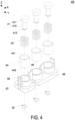
- the elastic component 40 further includes a sleeve 44 embedded in the accommodation seat 43.
- the sleeve 44 is a cylindrical sleeve.
- the sleeve 44 includes a top opening 441, a bottom portion 442 and a perforation 443.
- the perforation 443 is disposed on the bottom portion 442 and in communication with the top opening 441.
- the elastic element 42 is a telescopic spring and accommodated in the sleeve 44 through the top opening 441.
- the elastic element 42 is connected between the abutting element 41 and the bottom portion 442 of the sleeve 44.
- the abutting element 41 is partially accommodated in the sleeve 44 and includes an abutting portion 411 and a fitting portion 412.
- an area of the abutting portion 411 is greater than an area of the fitting portion 412 in the view of the docking direction (i.e., the Z axial direction). That is, the diameter of the abutting portion 411 is greater than the diameter of the fitting portion 412.
- the size of the fitting portion 412 is fit with the perforation 443 of the sleeve 44.
- a top end of the fitting portion 412 is connected to the abutting portion 411, and a bottom end of the fitting portion 412 passes through the perforation 443 on the bottom portion 442 of the sleeve 44.
- the abutting element 41 is allowed sliding relative to the sleeve 44 in the docking direction and abutting against the elastic element 42 so as to provide the restoring force.
- the elastic element 42 is a telescopic spring disposed around an outer periphery of the fitting portion 412 and connected between the abutting portion 411 and the bottom portion 442 of the sleeve 44.
- the fitting portion 412 includes an engaged slot 413 disposed at the bottom end of the fitting portion 412
- the elastic component 40 further includes an engaging ring 45.
- the elastic element 42 is preset in the sleeve 44, the bottom end of the fitting portion 412 passes through the elastic element 42 and the perforation 443 on the bottom portion 442 of the sleeve 44, and the engaging ring 45 and the engaged slot 413 are engaged with each other, so that the abutting element 41 is limited and not detached from the sleeve 44.
- the restoring force provided by the elastic element 42 acts between the abutting element 41 and the sleeve 44. Since the modular elastic component 40 has an assembling position matched to the corresponding positions of the output portion 31 of the output copper busbar 30 and the contact terminal 90 of the load 9, and the docking action of the inverter assembly 1 and the load 9, it helps to simplify the structural design of the elastic component 40, reduce the assembling cost, and improve the module commonality of elastic component 40. Certainly, the present disclosure is not limited thereto.
- the inverter assembly 1 is configured to dock with the load 9, so as to provide a three-phase AC output current to the load 9.
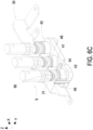
- the output current needs to be implemented through the electrical connection between the contact terminal 90 and the output portion 31 of the output copper busbar 30. Therefore, the output portion 31 and the contact terminal 90 face each other in the docking direction (i.e., the Z axial direction), as shown in FIGS. 6A and 7A .
- the electrical connection between the output portion 31 and the contact terminal 90 are implemented through the elastic component 40 below the output portion 31.
- the contact terminal 90 of the load 9 is in contact with the output portion 31 firstly, as shown in FIG. 6B and FIG. 7B .
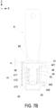
- the abutting element 41 of the elastic component 40 is located at an initial position, and a gap distance G is formed for example by the assembly tolerance and maintained between the abutting element 41 and the output portion 31.
- the gap distance G is zero. That is, when the contact terminal 90 of the load 9 is not in contact with the output portion 31, the abutting element 41 keeps interfering with the output portion 31.
- the present disclosure is not limited thereto.
- the contact terminal 90 of the load 9 is in contact with the output portion 31 and moved toward the installation surface 11 (i.e., in the inverse Z axial direction) by a first displacement distance D1.
- the contact terminal 90 abuts against the lower abutting element 41 through the output portion 31 and drives the abutting element 41 to move toward the installation surface 11 (i.e., in the inverse Z axial direction) by a second displacement distance D2.
- the first displacement distance D1 is greater than or equal to the second displacement distance D2.
- the difference between the first displacement distance D1 and the second displacement distance D2 is the aforementioned gap distance G, which is adjustable according the practical requirements.
- the output portion 31 has a thickness T in the view of the docking direction.
- the second displacement distance D2 is greater than or equal to the thickness T.
- the restoring force provided by the elastic element 42 is related to the displacement distance of the abutting element 41.
- the magnitude of the restoring force provided by the elastic element 42 is adjustable by controlling the displacement distance of the abutting element 41 in the docking direction. In other words, through the size design of the first displacement distance D1, the second displacement distance D2 and the thickness T, it ensures that the contact terminal 90 drives the output portion 31 and the abutting element 41 of the present disclosure to press down the elastic element 42 and generate the sufficient and stable restoring force.
- the output portion 31 is clamped firmly between the contact terminal 90 and the abutting element 41, and the electrical connection between the contact terminal 90 and the output portion 31 is maintained.
- the restoring force provided by the elastic component 40 acts only in the docking direction, and the abutment formed by the contact terminal 90 and the output portion 31 does not produce any fastened stress in other horizontal directions. The problem of poor contact between the inverter assembly 1 and the load 9 caused by the vibration during use is avoided.
- the present disclosure is not limited thereto.
- the elastic component 40 further includes a pair of spacer columns 46 disposed on the accommodation seat 43, spatially corresponding to the output portion 31, and arranged on two lateral sides of the sleeve 44.
- a height of the pair of spacer columns 46 relative to the accommodation seat 43 is greater than a height of the abutting element 41 maintained at an initial position relative to the accommodation seat 43, so as to form a height-difference distance H, as show in FIG. 7B .
- the space distance H is less than a thickness T of the output portion 31, so as to facilitate the alignment and assembly of the output portion 31 and the elastic component 40.
- a first width W1 is formed between the pair of spacer columns 46, the output portion 31 has a second width W2, and the first width W1 is greater than the second width W2 so as to further simplify the alignment and assembly of the output portion 31 and the elastic component 40.
- the present disclosure is not limited thereto.
- the present disclosure provides an inverter assembly.
- the inverter assembly includes an elastic component for abutting against the output copper busbar and the contact terminal and forming the contact therewith, so as to reduce the assembling cost the assembly tolerances of the inverter assembly sufficiently, and avoid the problem of poor contact caused by the vibration during use.
- the elastic component is stressed to provide a restoring force, which is used to push the output copper busbar abutting against the contact terminal to achieve the electrical connection between the output copper busbar and the contact terminal.
- the elastic component is not directly in contact with the contact terminal. Therefore, for the design of the elastic component, there is no need to consider the electrical impedance, and it makes the structure and the material design of the elastic component less restrictive, and is also beneficial to the insulation design.
- an output copper busbar and a contact terminal are electrically connected through the docking action to implement the DC electrical connection between the battery and the inverter or the AC electrical connection between the inverter and the load. There is no need to use the screwdriver and other tools to achieve the mutual electrical connection. Furthermore, since the output copper busbar and the contact terminal abut against each other through the modular elastic components, it facilitates to avoid the poor contact between the output copper busbar and the contact terminal due to the assembly tolerances during the docking action thereof.
- the modular elastic component Since the modular elastic component has an assembling position matched to the corresponding positions of the output copper busbar and the contact terminal, and the docking action of the inverter assembly, it helps to simplify the structural design of the elastic component, reduce the assembling cost, and improve the module commonality of elastic components. Moreover, the elastic components are arranged under the output copper busbars, and the docking action between the output copper busbars and the contact terminals is not affected by the elastic components. On the other hands, it allows to arrange a pair of spacer columns on the elastic components to correspond to the output portion of the output copper busbar, so as to simplify the alignment requirements during assembling.
- the restoring force provided by stressing the elastic components abuts against the output portion of the output copper busbar towards the contact terminal, so as to ensure that the output portion of the output copper busbar and the contact terminals of the load are abutted against each other and maintained the contact therebetween.
- the impact of stress due to vibration won't influence the contact between the output copper busbar and the contact terminal of the inverter assembly.
- the restoring force produced by the compression of the elastic components is sufficient to maintain the continuous and stable contact between the output portion of the output copper busbar and the contact terminal.
- the displacement distance of the contact terminal sliding relative to the output portion of the output copper busbar can be set when the inverter assembly is docked with the battery or the load, the restoring force generated by the output portion of the output copper busbar pushing against the elastic component can be controlled and adjusted within a specific range, so that the electrical contact between the output portion of the output copper busbar and the contact terminal is maintained stably, and the application of modular electrical connection is achieved.
Landscapes
- Engineering & Computer Science (AREA)
- Power Engineering (AREA)
- Microelectronics & Electronic Packaging (AREA)
- Inverter Devices (AREA)
Abstract
An inverter assembly (1) is disclosed and includes a base (10), a contact terminal (90), an output copper busbar (30) and an elastic component (40). The output copper busbar (30) is disposed on the base (10). The output copper busbar (30) includes an output portion (31) configured to electrically connect with the contact terminal (90). The elastic component (40) is disposed on the base (10) and includes an abutting element (41), an elastic element (42) and an accommodation seat (43). The accommodation seat (43) is disposed on the base (10), the abutting element (41) is connected to the accommodation seat (43) through the elastic element (42) along an axial direction. When the base (10) is docked with the contact terminal (90), the abutting element (41) of the elastic component (42) abuts against the output portion (31) to attach to the contact terminal (90), and the contact terminal (90) abuts against the abutting element (41) and the elastic element (42), so that a restoring force provided by the elastic element (42) keeps the output portion (31) abutting against the contact terminal (90).
Description
- The present disclosure relates to an electronic assembly structure, and more particularly to an inverter assembly having an elastic component for abutting against the output copper busbar and the contact terminal of the load and forming the contact therewith, so as to reduce the assembling cost of the inverter assembly sufficiently, and avoid the problem of poor contact caused by the vibration during use at the same time.
- Generally, an electronic device is often combined with a heat dissipation assembly to dissipate the internal heat. Since a high-efficiency power module used in the inverter is often accompanied with a lot of heat generated therefrom, the inverter assembly must be combined with a water-cooled heat dissipation module to achieve an effective effect of heat dissipation. Therefore, the high-power module is combined with the water-cooled heat dissipation module to form a heavy assembled structure. In use, an AC output terminal of the assembled structure of the inverter needs to be electrically connected to an AC input end of the motor.
- The AC output copper busbar of the conventional inverter needs to be connected to the AC input copper busbar of the motor through the screw or the rivet. However, for being connected through the screw or the rivet, the AC output copper busbar of the inverter must be aligned with the screw holes or rivet holes on the AC input copper busbar of the motor. Therefore, it is necessary to precisely control the dimensional tolerance of the copper busbars and the assembling tolerances of the inverter and the motor. Moreover, the cost of manufacturing or assembling is also increased. On the other hand, after being assembled, the dimensional tolerances may cause the stress problems, and it may cause the structural damage of the copper busbars. Furthermore, the poor contact may be caused due to the vibration and loosening during use.
- Therefore, there is a need of providing an inverter assembly having an elastic component for abutting against the output copper busbar and the contact terminal of the load and forming the contact therewith, so as to reduce the assembling cost of the inverter assembly sufficiently, avoid the problem of poor contact caused by the vibration during use, and obviate the drawbacks encountered by the prior arts.
- An object of the present disclosure is to provide an inverter assembly having an elastic component for abutting against the output copper busbar and the contact terminal and forming the contact therewith, so as to reduce the assembling cost of the inverter assembly sufficiently, and avoid the problem of poor contact caused by the vibration during use. On the other hand, the elastic component is stressed to provide a restoring force, which is used to push the output copper busbar abutting against the contact terminal to achieve the electrical connection between the output copper busbar and the contact terminal. The elastic component is not directly in contact with the contact terminal. Therefore, for the design of the elastic component, there is no need to consider the electrical impedance, and it makes the structure and the material design of the elastic component less restrictive, and is also beneficial to the insulation design.
- Another object of the present disclosure is to provide an inverter assembly. An output copper busbar and a contact terminal are electrically connected through the docking action to implement the DC electrical connection between the battery and the inverter or the AC electrical connection between the inverter and the load. There is no need to use the screwdriver and other tools to achieve the mutual electrical connection. Furthermore, since the output copper busbar and the contact terminal abut against each other through the modular elastic components, it facilitates to avoid the poor contact between the output copper busbar and the contact terminal due to the assembly tolerances during the docking action thereof. Since the modular elastic component has an assembling position matched to the corresponding positions of the output copper busbar and the contact terminal, and the docking action of the inverter assembly, it helps to simplify the structural design of the elastic component, reduce the assembling cost, and improve the module commonality of elastic components. Moreover, the elastic components are arranged under the output copper busbars, and the docking action between the output copper busbars and the contact terminals is not affected by the elastic components. On the other hands, it allows to arrange a pair of spacer columns on the elastic components to correspond to the output portion of the output copper busbar, so as to simplify the alignment requirements during assembling. In this way, the restoring force provided by stressing the elastic components abuts against the output portion of the output copper busbar towards the contact terminal, so as to ensure that the output portion of the output copper busbar and the contact terminals of the load are abutted against each other and maintained the contact therebetween. On the other hand, when the inverter assembly is docked with the battery or the load in using, the impact of stress due to vibration won't influence the contact between the output copper busbar and the contact terminal of the inverter assembly. The restoring force produced by the compression of the elastic components is sufficient to maintain the continuous and stable contact between the output portion of the output copper busbar and the contact terminal. Since the displacement distance of the contact terminal sliding relative to the output portion of the output copper busbar can be set when the inverter assembly is docked with the battery or the load, the restoring force generated by the output portion of the output copper busbar pushing against the elastic component can be controlled and adjusted within a specific range, so that the electrical contact between the output portion of the output copper busbar and the contact terminal is maintained stably, and the application of modular electrical connection is achieved.
- In accordance with an aspect of the present disclosure, an inverter assembly is provided and includes a base, a contact terminal, an output copper busbar and an elastic component. The output copper busbar is disposed on the base, wherein the output copper busbar includes an output portion spatially corresponding to the base and configured to form an electrical connection with the contact terminal. The elastic component is disposed on the base and includes an abutting element, an elastic element and an accommodation seat, wherein the accommodation seat is disposed on the base, the abutting element is connected to the accommodation seat through the elastic element along an axial direction, the elastic element provides a restoring force when the abutting element is stressed along the axial direction, and the abutting element is spatially corresponding to the output portion, wherein when the base is docked with the contact terminal, the abutting element of the elastic component abuts against the output portion to attach to the contact terminal, and the contact terminal abuts against the abutting element and the elastic element through the output portion, so that the restoring force provided by the elastic element keeps the output portion abutting against the contact terminal.
- In an embodiment, the output copper busbar is a DC output copper busbar connected to a power source, the power source is a DC power generated by a battery, and the contact terminal is connected to an inverter module, wherein when the base is docked with the contact terminal, the abutting element of the elastic component abuts against the output portion to attach to the contact terminal, and the contact terminal abuts against the abutting element and the elastic element through the output portion, so that the restoring force provided by the elastic element keeps the output portion abutting against the contact terminal, and the power source provides the inverter module with the DC power through the output copper busbar.
- In an embodiment, the contact terminal is connected to an power source, the power source is a DC power generated by a battery, the output copper busbar is connected to inverter module, and the output copper busbar is a DC output copper busbar, wherein when the base is docked with the contact terminal, the abutting element of the elastic component abuts against the output portion to attach to the contact terminal, and the contact terminal abuts against the abutting element and the elastic element through the output portion, so that the restoring force provided by the elastic element keeps the output portion abutting against the contact terminal, and the power source provides the inverter module with the DC power through the output copper busbar.
- In an embodiment, the contact terminal is connected to an power source, the power source is an AC power provided by an inverter module, and the output copper busbar is an AC output copper busbar and connected to a load, wherein when the base is docked with the contact terminal, the abutting element of the elastic component abuts against the output portion to attach to the contact terminal, and the contact terminal abuts against the abutting element and the elastic element through the output portion, so that the restoring force provided by the elastic element keeps the output portion abutting against the contact terminal, and the inverter module provides the load with the AC power from the power source through the output copper busbar.
- In an embodiment, the output copper busbar is an AC output copper busbar connected to a power source, the power source is an AC power generated by an inverter module, and the contact terminal is connected to a load, wherein when the base is docked with the contact terminal, the abutting element of the elastic component abuts against the output portion to attach to the contact terminal, and the contact terminal abuts against the abutting element and the elastic element through the output portion, so that the restoring force provided by the elastic element keeps the output portion abutting against the contact terminal, and the inverter module provides the load with the AC power from the power source through the output copper busbar.
- In an embodiment, the base includes an installation surface configured to dock with the load along a docking direction and attach to the contact terminal of the load, and the inverter module includes a power module disposed on the base and electrically connected to the output copper busbar, wherein when the base is docked with the contact terminal, the installation surface drives the elastic component and the output portion to attach to the contact terminal, the contact terminal abuts against the abutting element and the elastic element through the output portion, the abutting element is stressed along the axial direction, and the restoring force is provided by the elastic element to keeps the output portion abutting against the contact terminal, wherein when the contact terminal is not in contact with the output portion, the abutting element keeps interfering with the output portion.
- In an embodiment, the elastic component includes 3N of the abutting elements, N is an integer, and N ≧ 1.
- In an embodiment, the output portion is at least partially overlapped with the abutting element and at least partially overlapped with the contact terminal in view of the docking direction.
- In an embodiment, an area of the output portion is greater than an area of the abutting element, and greater than an area of the contact terminal in the view of the docking direction.
- In an embodiment, the elastic component further includes a sleeve embedded in the accommodation seat, the sleeve includes a top opening, a bottom portion and a perforation, the perforation is disposed on the bottom portion and in communication with the top opening, the elastic element is accommodated in the sleeve through the top opening, and the elastic element is connected between the abutting element and the bottom portion.
- In an embodiment, the abutting element is partially accommodated in the sleeve, and the elastic element is a telescopic spring accommodated in the sleeve through the top opening and connected between the abutting element and the bottom portion of the sleeve.
- In an embodiment, the abutting element includes an abutting portion and a fitting portion, and an area of the abutting portion is greater than an area of the fitting portion in view of the docking direction.
- In an embodiment, a top end of the fitting portion is connected to the abutting portion, a bottom end of the fitting portion passes through the perforation on the bottom portion of the sleeve, and the abutting element is allowed sliding relative to the sleeve in the docking direction and abutting against the elastic element so as to provide the restoring force.
- In an embodiment, the elastic element is disposed around an outer periphery of the fitting portion and connected between the abutting portion and the bottom portion of the sleeve, the fitting portion includes an engaged slot disposed at the bottom end of the fitting portion, and the elastic component further includes an engaging ring, wherein the bottom end of the fitting portion passes through the perforation on the bottom portion of the sleeve, and the engaging ring and the engaged slot are engaged with each other, so that the abutting element is limited and not detached from the sleeve.
- In an embodiment, the elastic component further includes a pair of spacer columns disposed on the accommodation seat, spatially corresponding to the output portion, and arranged on two lateral sides of the sleeve, and a height of the pair of spacer columns relative to the accommodation seat is greater than a height of the abutting element maintained at an initial position relative to the accommodation seat, so as to form a height-difference distance, wherein the height-difference distance is less than a thickness of the output portion.
- In an embodiment, a first width is formed between the pair of spacer columns, the output portion has a second width), and the first width is greater than the second width.
- In an embodiment, when the base is docked with the load, the contact terminal is in contact with the output portion and moved toward the installation surface by a first displacement distance, and the contact terminal abuts against the abutting element through the output portion and drives the abutting element to move toward the installation surface by a second displacement distance, wherein the first displacement distance is greater than or equal to the second displacement distance.
- In an embodiment, the output portion has a thickness in view of the docking direction, and the second displacement distance is greater than or equal to the thickness.
- In an embodiment, the output copper busbar is made of a soft-copper material, the accommodation seat is made of an insulation material, and the abutting element is made of a metal material, wherein a hardness of the metal material is greater than a hardness of the soft-copper material.
- The above contents of the present disclosure will become more readily apparent to those ordinarily skilled in the art after reviewing the following detailed description and accompanying drawings, in which:
-
FIG. 1 is a perspective structural view illustrating an inverter assembly and a load according to an embodiment of the present disclosure; -
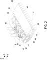
FIG. 2 is a perspective structural view illustrating the inverter assembly docked with the load according to the embodiment of the present disclosure; -
FIG. 3 is a perspective structural view illustrating the elastic component in the inverter assembly according to the embodiment of the present disclosure; -
FIG. 4 is an exploded view illustrating the elastic component in the inverter assembly according to the embodiment of the present disclosure; -
FIG. 5 is a cross-section view illustrating the elastic component in the inverter assembly according to the embodiment of the present disclosure; -
FIGS. 6A to 6C are perspective structural views show the docking action between the output copper busbar and the elastic component of the inverter assembly and the load according to the embodiment of the present disclosure; and -
FIGS. 7A to 7C are cross-section views show the relationship among the contact terminal, the output portion and the elastic component when the inverter assembly is docked with the load according to the embodiment of the present disclosure. - The present disclosure will now be described more specifically with reference to the following embodiments. It is to be noted that the following descriptions of preferred embodiments of this disclosure are presented herein for purpose of illustration and description only. It is not intended to be exhaustive or to be limited to the precise form disclosed. For example, the formation of a first feature over or on a second feature in the description that follows may include embodiments in which the first and second features are formed in direct contact, and may also include embodiments in which additional features may be formed between the first and second features, such that the first and second features may not be in direct contact. In addition, the present disclosure may repeat reference numerals and/or letters in the various examples. This repetition is for the purpose of simplicity and clarity and does not in itself dictate a relationship between the various embodiments and/or configurations discussed. Further, spatially relative terms, such as "top," "bottom," "upper," "lower" and the like, may be used herein for ease of description to describe one element or feature's relationship to another element(s) or feature(s) as illustrated in the figures. The spatially relative terms are intended to encompass different orientations of the device in use or operation in addition to the orientation depicted in the figures. The apparatus may be otherwise oriented (rotated 90 degrees or at other orientations) and the spatially relative descriptors used herein may likewise be interpreted accordingly. When an element is referred to as being "connected," or "coupled," to another element, it can be directly connected or coupled to the other element or intervening elements may be present. Although the wide numerical ranges and parameters of the present disclosure are approximations, numerical values are set forth in the specific examples as precisely as possible. In addition, although the "first," "second," "third," and the like terms in the claims be used to describe the various elements can be appreciated, these elements should not be limited by these terms, and these elements are described in the respective embodiments are used to express the different reference numerals, these terms are only used to distinguish one element from another element. For example, a first element could be termed a second element, and, similarly, a second element could be termed a first element, without departing from the scope of example embodiments.
- Please refer to
FIGS. 1 to 5 . In the embodiment, the present disclosure provides an inverter assembly 1 including abase 10, acontact terminal 90, anoutput copper busbar 30 and anelastic component 40. Theoutput copper busbar 30 is disposed on thebase 10. In the embodiment, theoutput copper busbar 30 includes anoutput portion 31 spatially corresponding to thebase 10 and configured to form an electrical connection with thecontact terminal 90. Theelastic component 40 is disposed on thebase 10 and includes an abuttingelement 41, anelastic element 42 and anaccommodation seat 43. In the embodiment, theaccommodation seat 43 is disposed on thebase 10, the abuttingelement 41 is connected to theaccommodation seat 43 through theelastic element 42 along an axial direction. Theelastic element 42 provides a restoring force when the abuttingelement 41 is stressed along the axial direction, and the abuttingelement 41 is spatially corresponding to theoutput portion 31. In the embodiment, when thebase 10 is docked with thecontact terminal 90, the abuttingelement 41 of theelastic component 40 abuts against theoutput portion 31 to attach to thecontact terminal 90, and thecontact terminal 90 abuts against the abuttingelement 41 and theelastic element 42 through theoutput portion 31. In this way, the restoring force provided by theelastic element 42 keeps theoutput portion 31 abutting against thecontact terminal 90. The electrical connection between theoutput copper busbar 30 and thecontact terminal 90 is achieved, and a power source is outputted. - Notably, the inverter assembly 1 of the present disclosure can be applied for DC output between the battery and the inverter module, or for AC output between the inverter module and a
load 9. In an embodiment, the power source can be for example but not limited to a DC power source generated by a battery. Theoutput copper busbar 30 is a DC output copper busbar and connected to the power source. Thecontact terminal 90 is connected to an inverter module. When thebase 10 is docked with thecontact terminal 90, the abuttingelement 41 of theelastic component 40 abuts against theoutput portion 31 to attach to thecontact terminal 90. Furthermore, thecontact terminal 90 is pushed against the abuttingelement 41 and theelastic element 42 through theoutput portion 31, and the restoring force provide by theelastic element 42 keeps theoutput portion 31 in contact with thecontact terminal 90. In that, the DC power of the battery is served as the power source, and the DC power is supplied to the inverter module through theoutput copper busbar 30. In another embodiment, thecontact terminal 90 is connected to an inverter module, and theoutput copper busbar 30 is connected to the power source. When thebase 10 is docked with thecontact terminal 90, the abuttingelement 41 of theelastic component 40 abuts against theoutput portion 31 to attach to thecontact terminal 90, and thecontact terminal 90 is pushed against the abuttingelement 41 and theelastic element 42 through theoutput portion 31. The restoring force provided by theelastic element 42 keeps theoutput portion 31 in contact with thecontact terminal 90. In that, the DC power of the battery is served as the power source, and the DC power is supplied to the inverter module through theoutput copper busbar 30. Furthermore, in an embodiment, thecontact terminal 90 is connected to the power source, and the power source is an AC power provided by the inverter module. Theoutput copper busbar 30 is an AC output copper busbar and connected to a load. When thebase 10 and thecontact terminal 90 are docked with each other, the abuttingelement 41 of theelastic component 40 abuts against theoutput portion 31 to attach to thecontact terminal 90, and thecontact terminal 90 pushes against the abuttingelement 41 and theelastic element 42 through theoutput portion 31. The restoring force provided by theelastic element 42 keeps theoutput portion 31 in contact with thecontact terminal 90. In that, the AC power provided by the inverter module is served as the power source, and the AC power is supplied to the load through theoutput copper busbar 30. In another embodiment, theoutput copper busbar 30 is an AC output copper busbar and connected to an AC power source, which is provided by an inverter module and served as a power source. Thecontact terminal 90 is connected to theload 9. When thebase 10 is docked with thecontact terminal 90, the abuttingelement 41 of the elastic component 4 abuts against theoutput portion 31 to attach to thecontact terminal 90, and thecontact terminal 90 pushes against the abuttingelement 41 and theelastic element 42 through theoutput portion 31. The restoring force provided by theelastic element 42 keeps theoutput portion 31 in contact with thecontact terminal 90. In that, the AC power provided by the inverter module is served as the power source, and the AC power is supplied to the load through theoutput copper busbar 30. In other words, the power source can be for example but not limited to an AC power or a DC power, which is connected to theoutput copper busbar 30 and then transmitted to thecontact terminal 90. Moreover, the AC power or the DC power transmitted to thecontact terminal 90 can be used by the load or the inverter module. On the contrary, the power source can be connected to thecontact terminal 90. The AC power or the DC power is transmitted to theoutput copper busbar 30. Thereafter, theoutput copper busbar 30 outputs the AC power or the DC power to the load or the inverter module for use. The combination of the inverter module connected to theoutput copper busbar 30 and theload 9 connected to thecontact terminal 90 for the AC power output is used in the following descriptions for illustration. The present disclosure is not limited thereto. - In the embodiment, the
base 10 includes aninstallation surface 11, for example the upper surface of thebase 10, configured to dock with theload 9 along a docking direction, such as the Z axial direction. When thebase 10 is docked with theload 9, theinstallation surface 11 is attached to thecontact terminal 90 of theload 9. In the embodiment, the inverter module includes apower module 20 disposed on theinstallation surface 11 of thebase 10. Preferably but not exclusively, thepower module 20 is stacked on the upper surface and the lower surface of the base. The present disclosure is not limited thereto. Preferably but not exclusively, in the embodiment, theoutput copper busbar 30 is an AC output copper busbar including aconnection portion 32 and electrically connected to thepower module 20. Certainly, the manner of disposing theoutput copper busbar 30 on the base or the electrical connection between theoutput copper busbar 30 and thepower module 20 is adjustable according to the practical requirements, and not limited thereto in the present disclosure. Notably, in the embodiment, theoutput copper busbar 30 includes theoutput portion 31 spatially corresponding to theinstallation surface 11. Furthermore, when thebase 10 is docked with theload 9, theoutput portion 31 of theoutput copper busbar 30 and thecontact terminal 90 of theload 9 are electrically connected with each other through the action of theelastic component 40. In the embodiment, theelastic component 40 is disposed on theinstallation surface 11 of thebase 10, and includes the abuttingelement 41, theelastic element 42 and theaccommodation seat 43. Preferably but not exclusively, in the embodiment, theaccommodation seat 43 is made of an insulation material and arranged on theinstallation surface 11 of thebase 10. The abuttingelement 41 is connected to theaccommodation seat 43 through theelastic element 42. Moreover, a restoring force is provided by theelastic element 42 when the abuttingelement 41 is forced toward theinstallation surface 11 in the axial direction. When thecontact terminal 90 is not in contact with theoutput portion 31, the abuttingelement 41 keeps interfering with theoutput portion 31. Certainly, the present disclosure is not limited thereto. In the embodiment, the abuttingelement 41 is spatially corresponding to theoutput portion 31 of theoutput copper busbar 30. When thebase 10 is docked with thecontact terminal 90, the installation surface drives theelastic component 40 and theoutput portion 31 of theoutput copper busbar 30 to attach to thecontact terminal 90, and thecontact terminal 90 abuts against the abuttingelement 41 and theelastic element 42 downwardly through theoutput portion 31. In that, the abuttingelement 41 is stressed along the axial direction, and the restoring force is provided by theelastic element 42 to keeps theoutput portion 31 of theoutput copper busbar 30 abutting against thecontact terminal 90 of theload 9. In this way, theoutput copper busbar 30 of the inverter assembly 1 and thecontact terminal 90 of theload 9 are electrically connected with each other through the docking action of the inverter assembly 1 and theload 9. There is no need to use the screwdriver and other tools to achieve the mutual electrical connection between theoutput copper busbar 30 of the inverter assembly 1 and thecontact terminal 90 of theload 9. In other words, the electrical connection between theoutput portion 31 of theoutput copper busbar 30 and theload 9 is achieved by utilizing the abutment of theelastic component 40, so as to reduce the assembling cost of the inverter assembly 1 and theload 9 sufficiently, and avoid the problem of poor contact caused by the vibration during use at the same time. - Notably, in the embodiment, the numbers of corresponding structures of the
contact terminal 90 of theload 9, theoutput portion 31 of theoutput copper busbar 30 and theelastic component 40 are three as an example for illustrating that the inverter assembly 1 has a three-phase AC output, and the present disclosure is not limited thereto. Preferably but not exclusively, in the embodiment, theelastic component 40 includes3N abutting elements 41, N is an integer, and N ≧ 1, so that theelastic component 40 is allowed to correspond to one single-phase output application or a multiphase output application. In other embodiments, the numbers of corresponding structures of thepower module 20, thecontact terminal 90 of theload 9, theoutput portion 31 of theoutput copper busbar 30 and theelastic component 40 are adjustable according to the practical requirements, and the present disclosure is not limited thereto. On the other hand, in the embodiment, theoutput copper busbar 30 is made of a soft-copper material, and the abuttingelement 41 is made of a metal material. A hardness of the metal material is greater than a hardness of the soft-copper material. In this way, when the inverter assembly 1 is docked with theload 9, the restoring force provided by theelastic component 40 through the abuttingelement 41 can fully act on theoutput portion 31, and make theoutput portion 31 more tightly abutted against the abuttingelement 41. In addition, theaccommodation seat 43 is made of an insulation material. When the abuttingelement 41 is connected to theaccommodation seat 43 through theelastic element 42, the electrical connection of theoutput copper busbar 30 or other circuits is not affected theaccommodation seat 43. Notably, theelastic component 40 is stressed to provide the restoring force, and further used to push theoutput copper busbar 30 against thecontact terminal 90 to achieve the electrical connection between theoutput copper busbar 30 and thecontact terminal 90. The abuttingelement 41, the elastic element and theaccommodation seat 43 of theelastic component 40 is not directly in contact with thecontact terminal 90. Therefore, for the design of theelastic component 40, there is no need to consider the electrical impedance, and it makes the structure and the material design of theelastic component 40 less restrictive, and is also beneficial to the insulation design. Certainly, the present disclosure is not limited thereto. - In the embodiment, the
output portion 31 of theoutput copper busbar 30 is at least partially overlapped with the abuttingelement 41 of theelastic component 40 in view of the docking direction (i.e., the Z axial direction). Moreover, when thebase 10 is docked with theload 9, theoutput portion 31, the abuttingelement 41 and thecontact terminal 90 are at least partially overlapped with each other. In this way, thecontact terminal 90 is driven to push against the lower abuttingelement 41 and theelastic element 42 through the output portion during the docking action of the inverter assembly 1 and theload 9. Certainly, in view of the docking direction (i.e., the Z axial direction), the larger the overlapping area of theoutput portion 31, the abuttingelement 41 and thecontact terminal 90, the more favorable it is to actuate the operation through the docking action, and reduce the impact of poor contact due to the assembly tolerances at the same time. Furthermore, an area of theoutput portion 31 is greater than an area of the abuttingelement 41, and greater than an area of thecontact terminal 90 in the view of the docking direction (i.e., the Z axial direction), and it also facilitates the restoring force of theelastic element 42 to act on theoutput portion 31, and avoids the poor contact between theoutput portion 31 and thecontact terminal 90 caused by the assembly tolerances during docking the inverter assembly 1 and theload 9. Certainly, the present disclosure is not limited thereto. - In the embodiment, the
elastic component 40 further includes asleeve 44 embedded in theaccommodation seat 43. Preferably but not exclusively, thesleeve 44 is a cylindrical sleeve. Thesleeve 44 includes atop opening 441, abottom portion 442 and aperforation 443. Theperforation 443 is disposed on thebottom portion 442 and in communication with thetop opening 441. Preferably but not exclusively, theelastic element 42 is a telescopic spring and accommodated in thesleeve 44 through thetop opening 441. Moreover, theelastic element 42 is connected between the abuttingelement 41 and thebottom portion 442 of thesleeve 44. In the embodiment, the abuttingelement 41 is partially accommodated in thesleeve 44 and includes an abuttingportion 411 and afitting portion 412. Preferably but not exclusively, an area of the abuttingportion 411 is greater than an area of thefitting portion 412 in the view of the docking direction (i.e., the Z axial direction). That is, the diameter of the abuttingportion 411 is greater than the diameter of thefitting portion 412. Preferably but not exclusively, the size of thefitting portion 412 is fit with theperforation 443 of thesleeve 44. In the embodiment, a top end of thefitting portion 412 is connected to the abuttingportion 411, and a bottom end of thefitting portion 412 passes through theperforation 443 on thebottom portion 442 of thesleeve 44. Moreover, the abuttingelement 41 is allowed sliding relative to thesleeve 44 in the docking direction and abutting against theelastic element 42 so as to provide the restoring force. Preferably but not exclusively, in the embodiment, theelastic element 42 is a telescopic spring disposed around an outer periphery of thefitting portion 412 and connected between the abuttingportion 411 and thebottom portion 442 of thesleeve 44. In addition, thefitting portion 412 includes an engagedslot 413 disposed at the bottom end of thefitting portion 412, and theelastic component 40 further includes an engagingring 45. In the embodiment, for disposing the abuttingelement 41 and theelastic element 42 on thesleeve 44, theelastic element 42 is preset in thesleeve 44, the bottom end of thefitting portion 412 passes through theelastic element 42 and theperforation 443 on thebottom portion 442 of thesleeve 44, and the engagingring 45 and the engagedslot 413 are engaged with each other, so that the abuttingelement 41 is limited and not detached from thesleeve 44. At the same time, the restoring force provided by theelastic element 42 acts between the abuttingelement 41 and thesleeve 44. Since the modularelastic component 40 has an assembling position matched to the corresponding positions of theoutput portion 31 of theoutput copper busbar 30 and thecontact terminal 90 of theload 9, and the docking action of the inverter assembly 1 and theload 9, it helps to simplify the structural design of theelastic component 40, reduce the assembling cost, and improve the module commonality ofelastic component 40. Certainly, the present disclosure is not limited thereto. - Please refer to
FIG. 1 ,FIG. 6A to FIG. 6C andFIG.7A to FIG. 7C . In the embodiment, the inverter assembly 1 is configured to dock with theload 9, so as to provide a three-phase AC output current to theload 9. The output current needs to be implemented through the electrical connection between thecontact terminal 90 and theoutput portion 31 of theoutput copper busbar 30. Therefore, theoutput portion 31 and thecontact terminal 90 face each other in the docking direction (i.e., the Z axial direction), as shown inFIGS. 6A and7A . In the embodiment, the electrical connection between theoutput portion 31 and thecontact terminal 90 are implemented through theelastic component 40 below theoutput portion 31. When the inverter assembly 1 and theload 9 are docked with each other, thecontact terminal 90 of theload 9 is in contact with theoutput portion 31 firstly, as shown inFIG. 6B andFIG. 7B . At this time, the abuttingelement 41 of theelastic component 40 is located at an initial position, and a gap distance G is formed for example by the assembly tolerance and maintained between the abuttingelement 41 and theoutput portion 31. Preferably but not exclusively, in other embodiments, the gap distance G is zero. That is, when thecontact terminal 90 of theload 9 is not in contact with theoutput portion 31, the abuttingelement 41 keeps interfering with theoutput portion 31. Certainly, the present disclosure is not limited thereto. After the inverter assembly 1 and theload 9 are docked and assembled, thecontact terminal 90 of theload 9 is in contact with theoutput portion 31 and moved toward the installation surface 11 (i.e., in the inverse Z axial direction) by a first displacement distance D1. At the same time, thecontact terminal 90 abuts against the lower abuttingelement 41 through theoutput portion 31 and drives the abuttingelement 41 to move toward the installation surface 11 (i.e., in the inverse Z axial direction) by a second displacement distance D2. Preferably but not exclusively, the first displacement distance D1 is greater than or equal to the second displacement distance D2. In the embodiment, the difference between the first displacement distance D1 and the second displacement distance D2 is the aforementioned gap distance G, which is adjustable according the practical requirements. Furthermore, in the embodiment, theoutput portion 31 has a thickness T in the view of the docking direction. Preferably but not exclusively, in the embodiment, the second displacement distance D2 is greater than or equal to the thickness T. Notably, the restoring force provided by theelastic element 42 is related to the displacement distance of the abuttingelement 41. The magnitude of the restoring force provided by theelastic element 42 is adjustable by controlling the displacement distance of the abuttingelement 41 in the docking direction. In other words, through the size design of the first displacement distance D1, the second displacement distance D2 and the thickness T, it ensures that thecontact terminal 90 drives theoutput portion 31 and the abuttingelement 41 of the present disclosure to press down theelastic element 42 and generate the sufficient and stable restoring force. Theoutput portion 31 is clamped firmly between thecontact terminal 90 and the abuttingelement 41, and the electrical connection between thecontact terminal 90 and theoutput portion 31 is maintained. On the other hand, the restoring force provided by theelastic component 40 acts only in the docking direction, and the abutment formed by thecontact terminal 90 and theoutput portion 31 does not produce any fastened stress in other horizontal directions. The problem of poor contact between the inverter assembly 1 and theload 9 caused by the vibration during use is avoided. Certainly, the present disclosure is not limited thereto. - In the embodiment, the
elastic component 40 further includes a pair ofspacer columns 46 disposed on theaccommodation seat 43, spatially corresponding to theoutput portion 31, and arranged on two lateral sides of thesleeve 44. A height of the pair ofspacer columns 46 relative to theaccommodation seat 43 is greater than a height of the abuttingelement 41 maintained at an initial position relative to theaccommodation seat 43, so as to form a height-difference distance H, as show inFIG. 7B . Preferably but not exclusively, the space distance H is less than a thickness T of theoutput portion 31, so as to facilitate the alignment and assembly of theoutput portion 31 and theelastic component 40. Moreover, in the embodiment, a first width W1 is formed between the pair ofspacer columns 46, theoutput portion 31 has a second width W2, and the first width W1 is greater than the second width W2 so as to further simplify the alignment and assembly of theoutput portion 31 and theelastic component 40. Certainly, the present disclosure is not limited thereto. - From the above, by utilizing the restoring force provided by the
elastic component 40 to push against theoutput portion 31 of theoutput copper busbar 30 and form the abutment with thecontact terminal 90 of theload 9, it facilitates to reduce the assembling cost and the assembly tolerances of the inverter assembly 1 and theload 9 sufficiently, and avoid the problem of poor contact caused by the vibration during use. Notably, the abutting force of theoutput portion 31 of theoutput copper busbar 30 corresponding to thecontact terminal 90 of theload 9 to form an electrical connection is implemented by changing the size design of theelastic component 40. The various combinations of the aforementioned features are adjustable according to the practical requirements. The present disclosure is not limited thereto. - In summary, the present disclosure provides an inverter assembly. The inverter assembly includes an elastic component for abutting against the output copper busbar and the contact terminal and forming the contact therewith, so as to reduce the assembling cost the assembly tolerances of the inverter assembly sufficiently, and avoid the problem of poor contact caused by the vibration during use. On the other hand, the elastic component is stressed to provide a restoring force, which is used to push the output copper busbar abutting against the contact terminal to achieve the electrical connection between the output copper busbar and the contact terminal. The elastic component is not directly in contact with the contact terminal. Therefore, for the design of the elastic component, there is no need to consider the electrical impedance, and it makes the structure and the material design of the elastic component less restrictive, and is also beneficial to the insulation design. In addition, an output copper busbar and a contact terminal are electrically connected through the docking action to implement the DC electrical connection between the battery and the inverter or the AC electrical connection between the inverter and the load. There is no need to use the screwdriver and other tools to achieve the mutual electrical connection. Furthermore, since the output copper busbar and the contact terminal abut against each other through the modular elastic components, it facilitates to avoid the poor contact between the output copper busbar and the contact terminal due to the assembly tolerances during the docking action thereof. Since the modular elastic component has an assembling position matched to the corresponding positions of the output copper busbar and the contact terminal, and the docking action of the inverter assembly, it helps to simplify the structural design of the elastic component, reduce the assembling cost, and improve the module commonality of elastic components. Moreover, the elastic components are arranged under the output copper busbars, and the docking action between the output copper busbars and the contact terminals is not affected by the elastic components. On the other hands, it allows to arrange a pair of spacer columns on the elastic components to correspond to the output portion of the output copper busbar, so as to simplify the alignment requirements during assembling. In this way, the restoring force provided by stressing the elastic components abuts against the output portion of the output copper busbar towards the contact terminal, so as to ensure that the output portion of the output copper busbar and the contact terminals of the load are abutted against each other and maintained the contact therebetween. On the other hand, when the inverter assembly is docked with the battery or the load in using, the impact of stress due to vibration won't influence the contact between the output copper busbar and the contact terminal of the inverter assembly. The restoring force produced by the compression of the elastic components is sufficient to maintain the continuous and stable contact between the output portion of the output copper busbar and the contact terminal. Since the displacement distance of the contact terminal sliding relative to the output portion of the output copper busbar can be set when the inverter assembly is docked with the battery or the load, the restoring force generated by the output portion of the output copper busbar pushing against the elastic component can be controlled and adjusted within a specific range, so that the electrical contact between the output portion of the output copper busbar and the contact terminal is maintained stably, and the application of modular electrical connection is achieved.
Claims (15)
- An inverter assembly (1) characterized by comprising:a base (10);a contact terminal (90);an output copper busbar (30) disposed on the base (10), wherein the output copper busbar (30) comprises an output portion (31) spatially corresponding to the base (10) and configured to form an electrical connection with the contact terminal (90); andan elastic component (40) disposed on the base (10) and comprising an abutting element (41), an elastic element (42) and an accommodation seat (43), wherein the accommodation seat (43) is disposed on the base (10), the abutting element (41) is connected to the accommodation seat (43) through the elastic element (42) along an axial direction, the elastic element (42) provides a restoring force when the abutting element (41) is stressed along the axial direction, and the abutting element (41) is spatially corresponding to the output portion (31), wherein when the base (10) is docked with the contact terminal (90), the abutting element (41) of the elastic component (40) abuts against the output portion (31) to attach to the contact terminal (90), and the contact terminal (90) abuts against the abutting element (41) and the elastic element (42) through the output portion (31), so that the restoring force provided by the elastic element (42) keeps the output portion (31) abutting against the contact terminal (90).
- The inverter assembly (1) according to claim 1, wherein the output copper busbar (30) is a DC output copper busbar connected to a power source, the power source is a DC power generated by a battery, and the contact terminal is connected to an inverter module, wherein when the base (10) is docked with the contact terminal (90), the abutting element (41) of the elastic component (40) abuts against the output portion (31) to attach to the contact terminal (90), and the contact terminal (90) abuts against the abutting element (41) and the elastic element (42) through the output portion (31), so that the restoring force provided by the elastic element (42) keeps the output portion (31) abutting against the contact terminal (90), and the power source provides the inverter module with the DC power through the output copper busbar (30).
- The inverter assembly (1) according to claim 1, wherein the contact terminal is connected to an power source, the power source is a DC power generated by a battery, the output copper busbar (30) is connected to inverter module, and the output copper busbar (30) is a DC output copper busbar, wherein when the base (10) is docked with the contact terminal (90), the abutting element (41) of the elastic component (40) abuts against the output portion (31) to attach to the contact terminal (90), and the contact terminal (90) abuts against the abutting element (41) and the elastic element (42) through the output portion (31), so that the restoring force provided by the elastic element (42) keeps the output portion (31) abutting against the contact terminal (90), and the power source provides the inverter module with the DC power through the output copper busbar (30).
- The inverter assembly (1) according to claim 1, wherein the contact terminal is connected to an power source, the power source is an AC power provided by an inverter module, and the output copper busbar (30) is an AC output copper busbar and connected to a load (9), wherein when the base (10) is docked with the contact terminal (90), the abutting element (41) of the elastic component (40) abuts against the output portion (31) to attach to the contact terminal (90), and the contact terminal (90) abuts against the abutting element (41) and the elastic element (42) through the output portion (31), so that the restoring force provided by the elastic element (42) keeps the output portion (31) abutting against the contact terminal (90), and the inverter module provides the load (9) with the AC power from the power source through the output copper busbar (30).
- The inverter assembly (1) according to claim 1, wherein the output copper busbar (30) is an AC output copper busbar connected to a power source, the power source is an AC power generated by an inverter module, and the contact terminal is connected to a load (9), wherein when the base (10) is docked with the contact terminal (90), the abutting element (41) of the elastic component (40) abuts against the output portion (31) to attach to the contact terminal (90), and the contact terminal (90) abuts against the abutting element (41) and the elastic element (42) through the output portion (31), so that the restoring force provided by the elastic element (42) keeps the output portion (31) abutting against the contact terminal (90), and the inverter module provides the load (9) with the AC power from the power source through the output copper busbar (30).
- The inverter assembly (1) according to claim 5, wherein the base (10) comprises an installation surface (11) configured to dock with the load (9) along a docking direction and attach to the contact terminal (90) of the load (9), and the inverter module comprises a power module (20) disposed on the base (10) and electrically connected to the output copper busbar (30), wherein when the base (10) is docked with the contact terminal (90), the installation surface drives the elastic component (40) and the output portion (31) to attach to the contact terminal (90), the contact terminal (90) abuts against the abutting element (41) and the elastic element (42) through the output portion (31), the abutting element (41) is stressed along the axial direction, and the restoring force is provided by the elastic element (42) to keeps the output portion (31) abutting against the contact terminal (90), wherein when the contact terminal (90) is not in contact with the output portion (31), the abutting element (41) keeps interfering with the output portion (31).
- The inverter assembly (1) according to claim 6, wherein the elastic component (40) comprises 3N of the abutting element (41), N is an integer, and N ≧ 1.
- The inverter assembly (1) according to claim 6, wherein the output portion (31) is at least partially overlapped with the abutting element (41) and at least partially overlapped with the contact terminal (90) in view of the docking direction.
- The inverter assembly (1) according to claim 6, wherein an area of the output portion (31) is greater than an area of the abutting element (41), and greater than an area of the contact terminal (90) in the view of the docking direction.
- The inverter assembly (1) according to claim 6, wherein the elastic component (40) further comprises a sleeve (44) embedded in the accommodation seat (43), the sleeve (44) comprises a top opening (441), a bottom portion (442) and a perforation (443), the perforation (443) is disposed on the bottom portion (442) and in communication with the top opening (441), the elastic element (42) is accommodated in the sleeve (44) through the top opening (441), and the elastic element (42) is connected between the abutting element (41) and the bottom portion (442).
- The inverter assembly (1) according to claim 10, wherein the abutting element (41) is partially accommodated in the sleeve (44), and the elastic element (42) is a telescopic spring accommodated in the sleeve (44) through the top opening (441) and connected between the abutting element (41) and the bottom portion (442) of the sleeve, wherein the abutting element (41) comprises an abutting portion (411) and a fitting portion (412), and an area of the abutting portion (411) is greater than an area of the fitting portion (412) in view of the docking direction.
- The inverter assembly (1) according to claim 11, wherein a top end of the fitting portion (412) is connected to the abutting portion (411), a bottom end of the fitting portion (412) passes through the perforation (443) on the bottom portion (442) of the sleeve (44), and the abutting element (41) is allowed sliding relative to the sleeve (44) in the docking direction and abutting against the elastic element (42) so as to provide the restoring force, wherein the elastic element (42) is disposed around an outer periphery of the fitting portion (412) and connected between the abutting portion (411) and the bottom portion (442) of the sleeve (44), the fitting portion (412) comprises an engaged slot (413) disposed at the bottom end of the fitting portion(412), and the elastic component (40) further comprises an engaging ring (45), wherein the bottom end of the fitting portion (412) passes through the perforation (443) on the bottom portion (442) of the sleeve (44), and the engaging ring (45) and the engaged slot (413) are engaged with each other, so that the abutting element (41) is limited and not detached from the sleeve (44).
- The inverter assembly (1) according to claim 10, wherein the elastic component (40) further comprises a pair of spacer columns (46) disposed on the accommodation seat (43), spatially corresponding to the output portion (31), and arranged on two lateral sides of the sleeve (44), and a height of the pair of spacer columns (46) relative to the accommodation seat (43) is greater than a height of the abutting element (41) maintained at an initial position relative to the accommodation seat (43), so as to form a height-difference distance (H), wherein the height-difference distance (H) is less than a thickness (T) of the output portion (31), wherein a first width (W1) is formed between the pair of spacer columns (46), the output portion (31) has a second width (W2), and the first width (W1) is greater than the second width (W2).
- The inverter assembly (1) according to claim 6, wherein when the base (10) is docked with the load (9), the contact terminal (90) is in contact with the output portion (31) and moved toward the installation surface (11) by a first displacement distance (D1), and the contact terminal (90) abuts against the abutting element (41) through the output portion (31) and drives the abutting element (41) to move toward the installation surface (11) by a second displacement distance (D2), wherein the first displacement distance (D1) is greater than or equal to the second displacement distance (D2), wherein the output portion (31) has a thickness (T) in view of the docking direction, and the second displacement distance (D2) is greater than or equal to the thickness (T).
- The inverter assembly (1) according to claim 1, wherein the output copper busbar (30) is made of a soft-copper material, the accommodation seat (43) is made of an insulation material, and the abutting element (41) is made of a metal material, wherein a hardness of the metal material is greater than a hardness of the soft-copper material.
Applications Claiming Priority (1)
| Application Number | Priority Date | Filing Date | Title |
|---|---|---|---|
| CN202310356808.2A CN118783154A (en) | 2023-04-06 | 2023-04-06 | Inverter assembly structure |
Publications (1)
| Publication Number | Publication Date |
|---|---|
| EP4444053A1 true EP4444053A1 (en) | 2024-10-09 |
Family
ID=86942720
Family Applications (1)
| Application Number | Title | Priority Date | Filing Date |
|---|---|---|---|
| EP23180962.5A Pending EP4444053A1 (en) | 2023-04-06 | 2023-06-22 | Inverter assembly |
Country Status (3)
| Country | Link |
|---|---|
| US (1) | US12355362B2 (en) |
| EP (1) | EP4444053A1 (en) |
| CN (1) | CN118783154A (en) |
Families Citing this family (1)
| Publication number | Priority date | Publication date | Assignee | Title |
|---|---|---|---|---|
| DE102021002030A1 (en) * | 2021-04-17 | 2022-10-20 | Kostal Kontakt Systeme Gmbh | connection unit |
Citations (3)
| Publication number | Priority date | Publication date | Assignee | Title |
|---|---|---|---|---|
| US20170301600A1 (en) * | 2016-04-18 | 2017-10-19 | Semikron Elektronik Gmbh & Co. Kg | Power electronics arrangement and vehicle with said arrangement |
| US20180337108A1 (en) * | 2017-05-17 | 2018-11-22 | Semikron Elektronik Gmbh & Co. Kg | Power electronic arrangement and electric vehicle with such an arrangement |
| US20200352041A1 (en) * | 2019-04-30 | 2020-11-05 | Semikron Elektronik Gmbh & Co.Kg | Power semiconductor module and method for arranging said power semiconductor module |
Family Cites Families (19)
| Publication number | Priority date | Publication date | Assignee | Title |
|---|---|---|---|---|
| US4920475A (en) | 1988-03-07 | 1990-04-24 | California Institute Of Technology | Integrated traction inverter and battery charger apparatus |
| US7753469B2 (en) * | 1997-07-15 | 2010-07-13 | Silverbrook Research Pty Ltd | Inkjet nozzle chamber with single inlet and plurality of nozzles |
| US6987670B2 (en) | 2003-05-16 | 2006-01-17 | Ballard Power Systems Corporation | Dual power module power system architecture |
| JP4194923B2 (en) * | 2003-11-28 | 2008-12-10 | 小島プレス工業株式会社 | Contact device |
| DE102008034663A1 (en) | 2007-07-30 | 2009-02-26 | GM Global Technology Operations, Inc., Detroit | Electric traction system for e.g. wagon, has inverter subsystem driving alternating current electric motor, and two sets of windings wound in slots configured as transformer for voltage matching between direct current energy sources |
| US8052427B2 (en) | 2009-04-01 | 2011-11-08 | GM Global Technology Operations LLC | Connector assembly for coupling an electric motor to a power source |
| US8169780B2 (en) | 2009-06-18 | 2012-05-01 | Honda Motor Co., Ltd. | Power conversion device |
| CN103023290B (en) | 2011-09-23 | 2015-11-25 | 台达电子企业管理(上海)有限公司 | Medium voltage converter drive system and total harmonic distortion compensating control method |
| TWI513167B (en) | 2013-10-22 | 2015-12-11 | Ind Tech Res Inst | Power conversion system for electric vehicles |
| US20150188249A1 (en) | 2013-12-31 | 2015-07-02 | Fabio Pereira | Ac cable assembly interconnection technologies for microinverter array |
| US10411387B2 (en) | 2015-10-28 | 2019-09-10 | Autonetworks Technologies, Ltd. | Terminal |
| JP6500771B2 (en) | 2015-12-25 | 2019-04-17 | 株式会社オートネットワーク技術研究所 | connector |
| US10594230B2 (en) | 2018-03-23 | 2020-03-17 | Sf Motors, Inc. | Inverter module having multiple half-bridge modules for a power converter of an electric vehicle |
| CN109889058A (en) | 2019-02-28 | 2019-06-14 | 中国第一汽车股份有限公司 | A current sharing busbar for inverters of new energy vehicles |
| US20210257927A1 (en) | 2020-02-13 | 2021-08-19 | Delta Electronics, Inc. | Inverter system |
| US11431258B2 (en) | 2020-12-22 | 2022-08-30 | Caterpillar Inc. | Scalable power inverter |
| DE102021202552A1 (en) | 2021-03-16 | 2022-09-22 | Robert Bosch Gesellschaft mit beschränkter Haftung | Multiple inverter with a heat sink |
| CN113241956A (en) | 2021-06-18 | 2021-08-10 | 中国第一汽车股份有限公司 | Inverter assembly |
| CN218477417U (en) | 2022-08-26 | 2023-02-14 | 华为数字能源技术有限公司 | Connector, motor controller, electricity drive assembly and vehicle |
-
2023
- 2023-04-06 CN CN202310356808.2A patent/CN118783154A/en active Pending
- 2023-06-21 US US18/212,631 patent/US12355362B2/en active Active
- 2023-06-22 EP EP23180962.5A patent/EP4444053A1/en active Pending
Patent Citations (3)
| Publication number | Priority date | Publication date | Assignee | Title |
|---|---|---|---|---|
| US20170301600A1 (en) * | 2016-04-18 | 2017-10-19 | Semikron Elektronik Gmbh & Co. Kg | Power electronics arrangement and vehicle with said arrangement |
| US20180337108A1 (en) * | 2017-05-17 | 2018-11-22 | Semikron Elektronik Gmbh & Co. Kg | Power electronic arrangement and electric vehicle with such an arrangement |
| US20200352041A1 (en) * | 2019-04-30 | 2020-11-05 | Semikron Elektronik Gmbh & Co.Kg | Power semiconductor module and method for arranging said power semiconductor module |
Also Published As
| Publication number | Publication date |
|---|---|
| US12355362B2 (en) | 2025-07-08 |
| CN118783154A (en) | 2024-10-15 |
| US20240339935A1 (en) | 2024-10-10 |
Similar Documents
| Publication | Publication Date | Title |
|---|---|---|
| CN110868044B (en) | power converter | |
| CN208608886U (en) | Power electronic equipment with D/C voltage connecting element | |
| CN111344823B (en) | DC link capacitor module, power electronic module and power electronic device | |
| US12355362B2 (en) | Inverter assembly | |
| US10389214B2 (en) | Motor and producing method for motor | |
| US9882421B2 (en) | Method and apparatus for increasing current capacity of a distributed drive system | |
| EP3611835B1 (en) | Electric power conversion device | |
| JP6492822B2 (en) | Rotating electrical machine structure | |
| JP2021141638A (en) | Power converter | |
| TWI834532B (en) | Inverter assembly | |
| JP6189798B2 (en) | Power converter | |
| JP6647350B2 (en) | Power converter | |
| JP2020107400A (en) | Bus bar fastening structure | |
| WO2019244491A1 (en) | Electric power converter | |
| US20210119476A1 (en) | Uninterruptible power supply and disconnection module | |
| JP2018196205A (en) | Electric power converting device | |
| JP2018198150A (en) | Insertion terminal device and switch | |
| KR100763167B1 (en) | Busbar connection device of switchgear | |
| WO2013103052A1 (en) | Power converter | |
| JP6604406B2 (en) | Power supply | |
| US12635102B2 (en) | Dual-inverter assembly | |
| EP4444052A1 (en) | Dual-inverter assembly | |
| WO2020161883A1 (en) | Power supply device and capacitor | |
| KR100755449B1 (en) | Inverter for welding machine where switching element and heat sink are in one-to-one contact | |
| JP2016063554A (en) | Power unit |
Legal Events
| Date | Code | Title | Description |
|---|---|---|---|
| PUAI | Public reference made under article 153(3) epc to a published international application that has entered the european phase |
Free format text: ORIGINAL CODE: 0009012 |
|
| STAA | Information on the status of an ep patent application or granted ep patent |
Free format text: STATUS: REQUEST FOR EXAMINATION WAS MADE |
|
| 17P | Request for examination filed |
Effective date: 20240304 |
|
| AK | Designated contracting states |
Kind code of ref document: A1 Designated state(s): AL AT BE BG CH CY CZ DE DK EE ES FI FR GB GR HR HU IE IS IT LI LT LU LV MC ME MK MT NL NO PL PT RO RS SE SI SK SM TR |