EP4444040A1 - Microwave oven - Google Patents
Microwave oven Download PDFInfo
- Publication number
- EP4444040A1 EP4444040A1 EP23166861.7A EP23166861A EP4444040A1 EP 4444040 A1 EP4444040 A1 EP 4444040A1 EP 23166861 A EP23166861 A EP 23166861A EP 4444040 A1 EP4444040 A1 EP 4444040A1
- Authority
- EP
- European Patent Office
- Prior art keywords
- air duct
- fan
- oven
- microwave oven
- inverter
- Prior art date
- Legal status (The legal status is an assumption and is not a legal conclusion. Google has not performed a legal analysis and makes no representation as to the accuracy of the status listed.)
- Granted
Links
Images


Classifications
-
- H—ELECTRICITY
- H05—ELECTRIC TECHNIQUES NOT OTHERWISE PROVIDED FOR
- H05B—ELECTRIC HEATING; ELECTRIC LIGHT SOURCES NOT OTHERWISE PROVIDED FOR; CIRCUIT ARRANGEMENTS FOR ELECTRIC LIGHT SOURCES, IN GENERAL
- H05B6/00—Heating by electric, magnetic or electromagnetic fields
- H05B6/64—Heating using microwaves
- H05B6/642—Cooling of the microwave components and related air circulation systems
Definitions
- the invention relates to a microwave oven.
- Modern cooking ovens often comprise different functions, besides a standard heating function for example a microwave heating function, a steam cooking function and/or a pyrolytic cleaning function. For each function special components are required. Further, most of said components must be cooled down.
- a magnetron for the microwave heating function requires an active cooling with a specific flow rate.
- a cooling fan blows an air stream directly or via a duct to the magnetron.
- said double-channel cooling system is driven by a double-inlet centrifugal fan. The one inlet is connected to a suction channel extending to the oven door and cavity exhaust, wherein sucked air keeps the oven door cool on the one hand and evacuates moist air from the cavity on the other hand.
- the other inlet is open, wherein air from a space between a cavity casing and a housing is sucked for cooling the housing and electronic elements.
- the outlet of the centrifugal fan is connected to a blowing channel through which the air is blown out of the cooling system.
- a cooking oven with microwave heating function and pyrolytic cleaning function comprises usually two cooling fans.
- the one cooling fan is provided for cooling the magnetron, while the other cooling fan drives the double-channel cooling system for cooling the oven door, the housing and the electronic elements (s. above).
- this concept is complex and expensive, since two cooling fans are required.
- the microwave oven comprises a cavity casing defining an oven cavity for treating food and electrical components comprising at least an inverter and a magnetron.
- the cavity casing comprises besides a top and a bottom wall as well as two opposing sidewalls and a rear wall a frontal opening that can be closed by a door.
- the microwave oven further comprises an oven housing enclosing the cavity casing and a component chamber positioned above the oven cavity wherein the electrical components are aligned.
- the electrical components are aligned at least partially on the cavity casing or an intermediate (or inner) carrier element (that serves e.g. for holding several components and/or the oven housing) that may be aligned on the cavity casing (and, thus, within the component chamber).
- the microwave oven comprises a cooling fan assembly.
- That cooling fan assembly comprises only one fan configured to ventilate the oven cavity (and/or an oven door) and to force cooling air through the inverter and the magnetron.
- the cooling fan assembly comprises an air duct that branches from a main channel connected to the fan into two air duct branches. A first one of such air duct branches is in fluid connection with the inverter and a second one of such air duct branches is in fluid connection with the magnetron.
- the invention integrates the ventilation of the cavity and/or the oven door with the cooling of the magnetron and the inverter. Additionally, the branching air duct for connecting the inverter and magnetron to the fan enables a better cooling efficiency than only ventilating a space between the cavity casing and the oven housing in which the inverter and magnetron are aligned.
- the air duct is in fluid connection with a suction side (or inlet side) of the fan.
- the fan is configured as a double inlet centrifugal fan.
- the fan preferably comprises a fan wheel with a double-sided suction functionality with respect to the opposing axial sides of the fan wheel.
- a first inlet of the fan is aligned at a first axial side of the fan (especially of the fan wheel) and a second inlet of the fan is aligned at a second axial side of the fan.
- both axial sides of the fan, especially the fan wheel are separated by a parting wall of the fan wheel, whereupon respective fan blades are aligned on each axial side.
- Such design makes it possible to use different blade shapes for each axial side so that each side may have different suction behavior.
- the first inlet of the fan is in fluid connection with the oven cavity and the second inlet is in fluid connection with at least the inverter and the magnetron, especially by means of the air duct.
- the first and second inlets and the respective ducts leading to them are fluidly separated, especially such that respective air streams within the ducts leading towards the fan would not be mixed up with each other.
- a fan outlet of the fan is in fluid connection with an outlet channel that in turn is connected to a front side of the oven housing.
- that outlet channel is connected to the outside and, especially, to an oven door cooling channel.
- the air duct is of a half or partial shell shape. That half or partial shell in combination with the cavity casing or the inner carrier element forms a closed cross section of the first and second air duct branches. That makes installation quite easy since elements to be cooled would not have to be installed within a pipe-like closed air channel.
- the inverter and/or the magnetron is positioned within the first or the second air duct branch, respectively. Such alignment within the respective air duct branch enables an improved individual cooling of the inverter and/or the magnetron, respectively.
- a shape of the cross section of the first and/or the second air duct branch is in parts adapted to the (especially outer) shape of the inverter or of the magnetron, respectively.
- the shape of the cross section of the respective air duct branch copies the respective cross section of the inverter or the magnetron.
- the shape of the cross section of the first and/or the second air duct branch follows the shape (especially the outer shape) of the inverter or of the magnetron at least partially.
- the respective first or second air duct branch of the air duct is (additionally to the adapted cross section) configured to follow the inverter or the magnetron in sections (or parts) along an air flow path.
- the respective air duct branch (especially seen in its longitudinal section) is preferably conformed to the inverter or magnetron, in distinct sections.
- the respective air duct branch has a clearance of about 1,5 to 4 mm, especially of 2 to 3 mm, between a component of the inverter or of the magnetron and a channel outer wall. This enables for maintaining an airflow at a higher velocity along the respective component's surface being cooled compared to e.g. a rectangular air duct branch that is not conformed to the inverter or magnetron.
- the air duct comprises a number of air blocking or air directing ribs that protrude into the air flow path.
- these ribs are aligned obliquely or perpendicular to a main flow direction within the respective air duct branch.
- These ribs serve for blocking an air flow within a distinct area (or region), especially within an area that does not require active cooling. Additionally or alternatively, these ribs serve for directing air flow to another area, especially an area that requires cooling.
- a cross section of the second air duct branch is narrowed with respect to the cross section of the magnetron.
- the corss section of the second air duct branch is narrowed with respect to the cross section of a cooling structure part of the magnetron.
- a magnetron is an assembly comprising also a cooling structure, preferably cooling fins, that makes up for only a part of the cross section (or geometrical "food print") of the magnetron.
- the first and the second air duct branch of the air duct are fluidly connected (directly or indirectly) to respective first and second vent openings within the oven housing.
- These first and second vent openings are preferably positioned within a rear sidewall and (especially longitudinal) sidewalls of the oven housing and these sidewalls are aligned obliquely or opposite to each other.
- the first air duct branch is directly connected to (or at least ends at) a backwards facing (i. e. the rear) sidewall within an area wherein at least a group of the first vent openings is aligned.
- the second air duct branch may end within the room between the cavity casing and the oven housing such that other vent openings (i.e. the second ones) are connected indirectly with the second air duct branch. In that case, the second air duct branch may be used also to cool other electrical components that are aligned within that room.
- the first and the second air duct branches of the air duct open into the direction of at least some of the first or second vent openings, respectively. That means that the respective air duct branch is directed with its longitudinal axis into the direction of the first or second vent openings, respectively.
- the electrical (or electronic) components comprise at least a main printed circuit board (“main PCB") which is mounted within an open flow path (i.e., the room between the cavity casing and the oven housing) between one of the first and second vent openings and the respective first or second air duct branch. Additionally, the electrical or electronic components may also comprise a user interface electronics that is mounted above the oven door cutout.
- main PCB main printed circuit board
- the fan is mounted with its rotation axis substantially normal to a top wall of the cavity casing or the aforementioned inner carrier element.
- substantially normal is preferably understood as 90 +/- about 10 degrees. Due to that alignment, short air flow path lengths or at least air flow paths with little rerouting may be accomplished.
- the first inlet of the fan is additionally in fluid connection with an oven door for cooling that oven door.
- the fluid connection is realized by means of a respective air duct.
- Fig. 1 shows a microwave oven 1.
- the microwave oven 1 comprises a cavity casing 2 which in turn defines an oven cavity 4 having a frontal opening 5 (cf. Fig. 3 ).
- the microwave oven 1 further comprises electrical components 6 that in turn comprise at least an inverter 8 (cf. Fig. 2 ) and a magnetron 10.
- the microwave oven 1 also comprises an oven housing (short: "housing 12") enclosing the cavity casing 2 and a component chamber 7 that is positioned above the cavity casing 2.
- the electrical components 6 are aligned within that component chamber 7.
- the microwave oven 1 comprises a cooling fan assembly 14. That cooling fan assembly 14 is configured - according to the embodiment shown in the figures - to ventilate and cool the oven cavity 4, an oven door 16 (for closing the frontal opening 5) and the electrical components 6.
- the cooling fan assembly 14 comprises only one fan 20 that is configured to ventilate the oven cavity 4 and to force cooling air through the inverter 8 and the magnetron 10, as well as to ventilate the oven door 16.
- the cooling fan assembly 14 comprises an air duct 22 that branches from a main channel 24 connected to the fan 20 into a first air duct branch 26 and a second air duct branch 28.
- the first air duct branch 26 is in fluid connection with the inverter 8 and the second channel 28 is in fluid connection with the magnetron 10.
- the fan 20 is designed as a double inlet centrifugal fan.
- the fan 20 comprises a fan wheel 30 and a fan wheel housing 32.
- the fan wheel 30 is configured with a parting wall 34 separating a first axial side 36 from a second axial side 38.
- the fan wheel housing 32 has a first inlet 40 corresponding with the first axial side 36 and a second inlet 42 corresponding with the second axial side 38 of the fan wheel 30.
- the fan wheel housing 32 also comprises an fan outlet 44, that is aligned in a direction radial to the fan wheel 30 (s. Fig. 3 ).
- the first inlet 40 is in fluid connection with a ventilation opening 46 of the oven cavity 4. Also, the first inlet 40 is in fluid connection with a oven door ventilation duct 48 (cf. Fig. 3 ). Also, the fan outlet 44 is in fluid connection with the door ventilation duct 48, especially at other positions than the first inlet 40. For that, the fan outlet 44 is fluidly connected to an outlet channel 50 that leads to the oven door 16. Preferably, the outlet channel 50 is designed to blow air through a slit above the oven door 16 such that a Venturi effect enables a suction effect to the oven door ventilation duct 48 (not shown in detail).
- the fan wheel housing 32 and the outlet channel 50 are realized in combination with an intermediate (or inner) carrier element (short: "carrier 52"; e.g. a plate or similar) that is mounted between the cavity casing 2 and the housing 12.
- carrier 52 e.g. a plate or similar
- the fan wheel housing 32 and the outlet channel 50 comprise respective half (or partial) shells that are mounted to the carrier 52 in order to form the complete fan wheel housing 32 as well as the outlet channel 50.
- another shell part 54 is mounted to the carrier 52 to form a ventilation duct 56 fluidly connected to the oven door ventilation duct 48 and to the ventilation opening 46 of the cavity casing 2.
- the second inlet 42 of the fan 20 is in fluid connection with the main channel 24 of the air duct 22.
- the air duct 22 also comprises a (half or partial) shell 60 (cf. Fig. 7 ) that is mounted to the carrier 52 and to the fan wheel housing 32 to form a closed cross section (cf. Fig. 2 and 3 ).
- the part of the shell 60 that in the intended assembly state (cf. Fig. 1 ) forms the first air duct branch 26 covers the inverter 8.
- the part of the shell 60 forming the second air duct branch 28 ends in the intended assembly state at the magnetron 10 (s. Fig. 1 and 4 ).
- the first air duct branch 26 ends adjacent to the rear sidewall 64 such that the most of the first vent opening 62 aligned in that part open into the second air duct branch 26.
- the second vent openings 68 open up into the room between the carrier 52 and a top wall 72 of the housing 12. In that room the electrical components 6 (also e.g., a main PCB 74 and a user interface 76) are aligned.
- the air within that room is mainly sucked by means of the second air duct branch 28 through the magnetron 10.
- the respective part of the shell 60 has indentations 80 from its outside in order to reduce a distance between the channel outer wall ("shell wall 82") in the region where the inverter 8 is placed.
- These indentations 80 are chosen such that the first air duct branch 26 conforms to the outer structure (shape) of the inverter 8 (cf. Fig. 5 ).
- these indentations 80 are also shaped in the direction of the air flow through the first air duct branch 26 to follow the shape of the inverter 8 (cf. Fig. 6 ) such that the outer surface of the shell wall 82 shows some kind of hump 84.
- the indentations 80 are formed such that the distance between the shell wall 82 and several of the components of the inverter 8 is about 2 to 3 mm. By that a higher air flow velocity may be reached around the respective components of the inverter 8 compared to a rectangular cross section of the first air duct branch 26.
- first air duct branch 26 some ribs are placed. There are blocking ribs 90 that serve for blocking air flow from areas (or regions) where no cooling or less cooling is needed. Also, there is an air direction rib 92 that separates a flow path 94 within the first air duct branch 26. In that flow path 94 a heatsink 96 of the inverter 8 is aligned.
- the second air duct branch 28 comprises a connecting end 100 that has a narrower cross section than a cooling structure part 102 of the magnetron 10. That enables a focused air flow through the cooling structure part 102 and, thus, along cooling fins 104 aligned therein.
Landscapes
- Physics & Mathematics (AREA)
- Electromagnetism (AREA)
- Electric Ovens (AREA)
Abstract
Description
- The invention relates to a microwave oven.
- Modern cooking ovens often comprise different functions, besides a standard heating function for example a microwave heating function, a steam cooking function and/or a pyrolytic cleaning function. For each function special components are required. Further, most of said components must be cooled down.
- For example, a magnetron for the microwave heating function requires an active cooling with a specific flow rate. Usually, a cooling fan blows an air stream directly or via a duct to the magnetron. In case of a cooking oven with pyrolytic cleaning function, the housing, the oven door and the electronic circuits are usually kept cool by a double-channel cooling system for safety and functionality reasons. For example, said double-channel cooling system is driven by a double-inlet centrifugal fan. The one inlet is connected to a suction channel extending to the oven door and cavity exhaust, wherein sucked air keeps the oven door cool on the one hand and evacuates moist air from the cavity on the other hand. The other inlet is open, wherein air from a space between a cavity casing and a housing is sucked for cooling the housing and electronic elements. The outlet of the centrifugal fan is connected to a blowing channel through which the air is blown out of the cooling system.
- A cooking oven with microwave heating function and pyrolytic cleaning function comprises usually two cooling fans. The one cooling fan is provided for cooling the magnetron, while the other cooling fan drives the double-channel cooling system for cooling the oven door, the housing and the electronic elements (s. above). However, this concept is complex and expensive, since two cooling fans are required.
- It is an object of the present invention to improve cooling of a microwave oven.
- That object is solved by a microwave oven with the features of
claim 1. Additional expedient and/or per se inventive embodiments are described in the dependent claims and the following specification. - The microwave oven according to the invention comprises a cavity casing defining an oven cavity for treating food and electrical components comprising at least an inverter and a magnetron. The cavity casing comprises besides a top and a bottom wall as well as two opposing sidewalls and a rear wall a frontal opening that can be closed by a door. The microwave oven further comprises an oven housing enclosing the cavity casing and a component chamber positioned above the oven cavity wherein the electrical components are aligned. Especially, the electrical components are aligned at least partially on the cavity casing or an intermediate (or inner) carrier element (that serves e.g. for holding several components and/or the oven housing) that may be aligned on the cavity casing (and, thus, within the component chamber). Also, the microwave oven comprises a cooling fan assembly. That cooling fan assembly comprises only one fan configured to ventilate the oven cavity (and/or an oven door) and to force cooling air through the inverter and the magnetron. Further, the cooling fan assembly comprises an air duct that branches from a main channel connected to the fan into two air duct branches. A first one of such air duct branches is in fluid connection with the inverter and a second one of such air duct branches is in fluid connection with the magnetron.
- In other words, the invention integrates the ventilation of the cavity and/or the oven door with the cooling of the magnetron and the inverter. Additionally, the branching air duct for connecting the inverter and magnetron to the fan enables a better cooling efficiency than only ventilating a space between the cavity casing and the oven housing in which the inverter and magnetron are aligned.
- According to a preferred embodiment, the air duct is in fluid connection with a suction side (or inlet side) of the fan.
- According to an expedient embodiment, the fan is configured as a double inlet centrifugal fan. For that, the fan preferably comprises a fan wheel with a double-sided suction functionality with respect to the opposing axial sides of the fan wheel. Especially, a first inlet of the fan is aligned at a first axial side of the fan (especially of the fan wheel) and a second inlet of the fan is aligned at a second axial side of the fan. Preferably, both axial sides of the fan, especially the fan wheel, are separated by a parting wall of the fan wheel, whereupon respective fan blades are aligned on each axial side. Such design makes it possible to use different blade shapes for each axial side so that each side may have different suction behavior.
- According to a preferred embodiment, the first inlet of the fan is in fluid connection with the oven cavity and the second inlet is in fluid connection with at least the inverter and the magnetron, especially by means of the air duct. According to a preferred variant, the first and second inlets and the respective ducts leading to them are fluidly separated, especially such that respective air streams within the ducts leading towards the fan would not be mixed up with each other.
- According to an expedient embodiment, a fan outlet of the fan is in fluid connection with an outlet channel that in turn is connected to a front side of the oven housing. Here, that outlet channel is connected to the outside and, especially, to an oven door cooling channel.
- According to a preferred embodiment, the air duct is of a half or partial shell shape. That half or partial shell in combination with the cavity casing or the inner carrier element forms a closed cross section of the first and second air duct branches. That makes installation quite easy since elements to be cooled would not have to be installed within a pipe-like closed air channel.
- According to a preferred embodiment, the inverter and/or the magnetron is positioned within the first or the second air duct branch, respectively. Such alignment within the respective air duct branch enables an improved individual cooling of the inverter and/or the magnetron, respectively.
- According to a preferred further development of the aforementioned embodiment, a shape of the cross section of the first and/or the second air duct branch is in parts adapted to the (especially outer) shape of the inverter or of the magnetron, respectively. Especially, the shape of the cross section of the respective air duct branch copies the respective cross section of the inverter or the magnetron. I.e., the shape of the cross section of the first and/or the second air duct branch follows the shape (especially the outer shape) of the inverter or of the magnetron at least partially.
- According to an expedient further development, the respective first or second air duct branch of the air duct is (additionally to the adapted cross section) configured to follow the inverter or the magnetron in sections (or parts) along an air flow path. I.e., the respective air duct branch (especially seen in its longitudinal section) is preferably conformed to the inverter or magnetron, in distinct sections. Especially, the respective air duct branch has a clearance of about 1,5 to 4 mm, especially of 2 to 3 mm, between a component of the inverter or of the magnetron and a channel outer wall. This enables for maintaining an airflow at a higher velocity along the respective component's surface being cooled compared to e.g. a rectangular air duct branch that is not conformed to the inverter or magnetron.
- According to an expedient embodiment, the air duct comprises a number of air blocking or air directing ribs that protrude into the air flow path. Preferably, these ribs are aligned obliquely or perpendicular to a main flow direction within the respective air duct branch. These ribs serve for blocking an air flow within a distinct area (or region), especially within an area that does not require active cooling. Additionally or alternatively, these ribs serve for directing air flow to another area, especially an area that requires cooling.
- According to a further expedient embodiment, especially wherein the magnetron is not aligned within the second air duct branch, a cross section of the second air duct branch is narrowed with respect to the cross section of the magnetron. Preferably, the corss section of the second air duct branch is narrowed with respect to the cross section of a cooling structure part of the magnetron. Usually, a magnetron is an assembly comprising also a cooling structure, preferably cooling fins, that makes up for only a part of the cross section (or geometrical "food print") of the magnetron. By narrowing the air duct branch, the air flow through the magnetron may be focused to the cooling structure, making cooling more efficient.
- According to a preferred embodiment, the first and the second air duct branch of the air duct are fluidly connected (directly or indirectly) to respective first and second vent openings within the oven housing. These first and second vent openings are preferably positioned within a rear sidewall and (especially longitudinal) sidewalls of the oven housing and these sidewalls are aligned obliquely or opposite to each other. For example, the first air duct branch is directly connected to (or at least ends at) a backwards facing (i. e. the rear) sidewall within an area wherein at least a group of the first vent openings is aligned. The second air duct branch may end within the room between the cavity casing and the oven housing such that other vent openings (i.e. the second ones) are connected indirectly with the second air duct branch. In that case, the second air duct branch may be used also to cool other electrical components that are aligned within that room.
- Preferably, the first and the second air duct branches of the air duct open into the direction of at least some of the first or second vent openings, respectively. That means that the respective air duct branch is directed with its longitudinal axis into the direction of the first or second vent openings, respectively.
- According to an expedient variant, the electrical (or electronic) components comprise at least a main printed circuit board ("main PCB") which is mounted within an open flow path (i.e., the room between the cavity casing and the oven housing) between one of the first and second vent openings and the respective first or second air duct branch. Additionally, the electrical or electronic components may also comprise a user interface electronics that is mounted above the oven door cutout.
- According to a preferred embodiment, the fan, especially the fan wheel, is mounted with its rotation axis substantially normal to a top wall of the cavity casing or the aforementioned inner carrier element. Substantially normal is preferably understood as 90 +/- about 10 degrees. Due to that alignment, short air flow path lengths or at least air flow paths with little rerouting may be accomplished.
- According to an expedient embodiment, the first inlet of the fan is additionally in fluid connection with an oven door for cooling that oven door. Especially, the fluid connection is realized by means of a respective air duct.
- The conjunction "and/or" is to be understood here and in the following in particular in such a way that the features linked by means of this conjunction may be realized both together as well as alternatives to each other.
- An embodiment of the invention described before will be described by means of a drawing. Therein show:
- Fig. 1
- in a partly translucent and cut open perspective view a microwave oven,
- Fig. 2
- in a view according
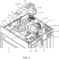
Fig. 1 the microwave oven in a partly exploded view, - Fig. 3
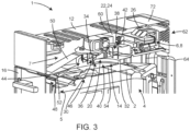
- in a partly cut view the microwave oven,
- Fig. 4
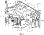
- in a detailed view a cooling fan assembly of the microwave oven,
- Fig. 5
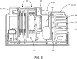
- in a cross-sectional view the cooling fan assembly,
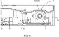
- Fig. 6
- in a longitudinally sectional view the cooling fan assembly, and
- Fig. 7
- in a schematic perspective view an air duct of the cooling fan assembly.
- Corresponding parts are always given the same reference signs in all figures.
-
Fig. 1 shows amicrowave oven 1. Themicrowave oven 1 comprises acavity casing 2 which in turn defines anoven cavity 4 having a frontal opening 5 (cf.Fig. 3 ). Themicrowave oven 1 further compriseselectrical components 6 that in turn comprise at least an inverter 8 (cf.Fig. 2 ) and amagnetron 10. Themicrowave oven 1 also comprises an oven housing (short: "housing 12") enclosing thecavity casing 2 and acomponent chamber 7 that is positioned above thecavity casing 2. Theelectrical components 6 are aligned within thatcomponent chamber 7. Further, themicrowave oven 1 comprises a coolingfan assembly 14. That coolingfan assembly 14 is configured - according to the embodiment shown in the figures - to ventilate and cool theoven cavity 4, an oven door 16 (for closing the frontal opening 5) and theelectrical components 6. - As shown in more detail in the following figures the cooling
fan assembly 14 comprises only onefan 20 that is configured to ventilate theoven cavity 4 and to force cooling air through theinverter 8 and themagnetron 10, as well as to ventilate theoven door 16. The coolingfan assembly 14 comprises an air duct 22 that branches from amain channel 24 connected to thefan 20 into a firstair duct branch 26 and a secondair duct branch 28. The firstair duct branch 26 is in fluid connection with theinverter 8 and thesecond channel 28 is in fluid connection with themagnetron 10. - As it can be seen in more detail from
Fig. 2 and3 thefan 20 is designed as a double inlet centrifugal fan. I.e., thefan 20 comprises afan wheel 30 and afan wheel housing 32. Thefan wheel 30 is configured with aparting wall 34 separating a firstaxial side 36 from a secondaxial side 38. Thefan wheel housing 32 has afirst inlet 40 corresponding with the firstaxial side 36 and asecond inlet 42 corresponding with the secondaxial side 38 of thefan wheel 30. Thefan wheel housing 32 also comprises anfan outlet 44, that is aligned in a direction radial to the fan wheel 30 (s.Fig. 3 ). - The
first inlet 40 is in fluid connection with aventilation opening 46 of theoven cavity 4. Also, thefirst inlet 40 is in fluid connection with a oven door ventilation duct 48 (cf.Fig. 3 ). Also, thefan outlet 44 is in fluid connection with thedoor ventilation duct 48, especially at other positions than thefirst inlet 40. For that, thefan outlet 44 is fluidly connected to anoutlet channel 50 that leads to theoven door 16. Preferably, theoutlet channel 50 is designed to blow air through a slit above theoven door 16 such that a Venturi effect enables a suction effect to the oven door ventilation duct 48 (not shown in detail). - The
fan wheel housing 32 and theoutlet channel 50 are realized in combination with an intermediate (or inner) carrier element (short: "carrier 52"; e.g. a plate or similar) that is mounted between thecavity casing 2 and thehousing 12. Thefan wheel housing 32 and theoutlet channel 50 comprise respective half (or partial) shells that are mounted to thecarrier 52 in order to form the completefan wheel housing 32 as well as theoutlet channel 50. Also, anothershell part 54 is mounted to thecarrier 52 to form a ventilation duct 56 fluidly connected to the ovendoor ventilation duct 48 and to theventilation opening 46 of thecavity casing 2. - The
second inlet 42 of thefan 20 is in fluid connection with themain channel 24 of the air duct 22. The air duct 22 also comprises a (half or partial) shell 60 (cf.Fig. 7 ) that is mounted to thecarrier 52 and to thefan wheel housing 32 to form a closed cross section (cf.Fig. 2 and3 ). The part of theshell 60 that in the intended assembly state (cf.Fig. 1 ) forms the firstair duct branch 26 covers theinverter 8. The part of theshell 60 forming the secondair duct branch 28 ends in the intended assembly state at the magnetron 10 (s.Fig. 1 and4 ). Thus, during intended operation of thefan 20 air is forced, in fact sucked, through theinverter 8 and themagnetron 10 into the direction of thesecond inlet 42, thereby cooling the respective components of theinverter 8 and themagnetron 10, respectively. - The air enters through
first vent openings 62 that are aligned in a rear sidewall 64 and asidewall 66 of thehousing 12 as well as throughsecond vent openings 68 that are aligned in theopposite sidewall 70. The firstair duct branch 26 ends adjacent to the rear sidewall 64 such that the most of the first vent opening 62 aligned in that part open into the secondair duct branch 26. Thesecond vent openings 68 open up into the room between thecarrier 52 and atop wall 72 of thehousing 12. In that room the electrical components 6 (also e.g., amain PCB 74 and a user interface 76) are aligned. The air within that room is mainly sucked by means of the secondair duct branch 28 through themagnetron 10. In the intended operational state of themicrowave oven 1 there is a ventilation gap between theoven door 16 as well as thesidewalls microwave oven 1 is installed. Through that gap air may be sucked and enter through the first and second vent opening 62 and 68 (not shown in detail). - In order to improve cooling effect of the air within the first
air duct branch 26 the respective part of theshell 60 hasindentations 80 from its outside in order to reduce a distance between the channel outer wall ("shell wall 82") in the region where theinverter 8 is placed. Theseindentations 80 are chosen such that the firstair duct branch 26 conforms to the outer structure (shape) of the inverter 8 (cf.Fig. 5 ). However, theseindentations 80 are also shaped in the direction of the air flow through the firstair duct branch 26 to follow the shape of the inverter 8 (cf.Fig. 6 ) such that the outer surface of theshell wall 82 shows some kind of hump 84. Theindentations 80 are formed such that the distance between theshell wall 82 and several of the components of theinverter 8 is about 2 to 3 mm. By that a higher air flow velocity may be reached around the respective components of theinverter 8 compared to a rectangular cross section of the firstair duct branch 26. - Additionally, within the first
air duct branch 26 some ribs are placed. There are blockingribs 90 that serve for blocking air flow from areas (or regions) where no cooling or less cooling is needed. Also, there is anair direction rib 92 that separates aflow path 94 within the firstair duct branch 26. In that flow path 94 aheatsink 96 of theinverter 8 is aligned. - Further, as it may be seen in
Fig. 2 and4 , the secondair duct branch 28 comprises a connectingend 100 that has a narrower cross section than a cooling structure part 102 of themagnetron 10. That enables a focused air flow through the cooling structure part 102 and, thus, along cooling fins 104 aligned therein. - The subject matter of the invention is not limited to the embodiment described above. Rather, further embodiments of the invention can be derived by the skilled person from the above description.
-
- 1
- microwave oven
- 2
- cavity casing
- 5
- frontal opening
- 4
- cavity
- 6
- electrical components
- 7
- component chamber
- 8
- inverter
- 10
- magnetron
- 12
- housing
- 14
- cooling fan assembly
- 16
- oven door
- 20
- fan
- 22
- air duct
- 24
- main channel
- 26
- first air duct branch
- 28
- second air duct branch
- 30
- fan wheel
- 32
- fan wheel housing
- 34
- parting wall
- 36
- first axial side
- 38
- second axial side
- 40
- first inlet
- 42
- second inlet
- 44
- fan outlet
- 46
- ventilation opening
- 48
- oven door ventilation duct
- 50
- outlet channel
- 52
- carrier
- 54
- shell part
- 56
- ventilation duct
- 60
- shell
- 62
- first vent opening
- 64
- rear sidewall
- 66
- sidewall
- 68
- second vent opening
- 70
- sidewall
- 72
- top wall
- 74
- main PCB
- 76
- user interface
- 80
- indentation
- 82
- shell wall
- 84
- hump
- 90
- blocking rib
- 92
- direction rib
- 94
- flow path
- 96
- heatsink
- 100
- connecting end
- 102
- cooling structure part
- 104
- cooling fins
Claims (15)
- Microwave oven (1), comprising- a cavity casing (2) defining an oven cavity (4) for treating food, the cavity casing (2) comprising a frontal opening (5) that can be closed by a door (16),- electrical components (6) comprising at least an inverter (8) and a magnetron (10),- an oven housing (12) enclosing the cavity casing (2) and a component chamber (7) above the oven cavity (4) wherein the electrical components (6) are aligned, and- a cooling fan assembly (14),whereinthe cooling fan assembly (14) comprises one fan (20) configured to ventilate the oven cavity (4) and/or an oven door (16) and to force cooling air through the inverter (8) and the magnetron (10), andthe cooling fan assembly (14) comprises an air duct (22) that branches from a main channel (24) connected to the fan (20) into two air duct branches (26, 28), a first one of such air duct branches (26) being in fluid connection with the inverter (8) and a second one of such air duct branches (28) being in fluid connection with the magnetron (10).
- Microwave oven (1) according to claim 1,
wherein the air duct (22) is in fluid connection with a suction side of the fan (20). - Microwave oven (1) according to claim 2,wherein the fan (20) is configured as a double inlet centrifugal fan type, and wherein a first inlet (40) of the fan (20) is aligned at a first axial side (36) of the fan (20) andwherein a second inlet (42) of the fan (20) is aligned at a second axial side (38) of the fan (20).
- Microwave oven (1) according to claim 2 and 3,
wherein a first inlet (40) of the fan (20) is in fluid connection with the oven cavity (4) and wherein a second inlet (42) is in fluid connection with at least the inverter (8) and the magnetron (10), especially by means of the air duct (22) . - Microwave oven (1) according to one of claims 1 to 4,
wherein a fan outlet (44) of the fan (20) is in fluid connection with an outlet channel (50) connected to a front side of the oven housing (12). - Microwave oven (1) according to one of claims 1 to 5,
wherein the air duct (22) is of a half or partial shell shape which in combination with the cavity casing (2) or an inner carrier element (52) forms a closed cross section of the first and second air duct branches (26, 28). - Microwave oven (1) according to one of claims 1 to 6,
wherein the inverter (8) and/or the magnetron (10) is positioned within the first or the second air duct branch (26, 28), respectively. - Microwave oven (1) according to claim 7,
wherein a shape of the cross section of the first air duct branch (26) is in parts adapted to the shape of the inverter (8), respectively, especially to the respective cross section of the inverter (8). - Microwave oven (1) according to claim 8,
wherein the first air duct branch (26) is configured to follow the inverter (8) in sections along an air flow path with a clearance of about 1,5 to 4 mm, especially of 2 to 3 mm, between a component of the inverter (8) and a channel outer wall (82). - Microwave oven (1) according to claim 8 or 9,
wherein the air duct (22) comprises a number of air blocking or air directing ribs (90, 92) that protrude into the air flow path, that serve for blocking an air flow within a distinct area, especially that does not require active cooling, and/or for directing air flow to another area, especially that requires cooling. - Microwave oven (1) according to one of claims 1 to 10,
wherein a cross section of the second air duct branch (28) is narrowed with respect to the cross section of the magnetron (10), especially of a cooling structure part (102) of the magnetron (10). - Microwave oven (1) according to one of claims 1 to 11,
wherein the first and the second air duct branch (26, 28) of the air duct (22) are fluidly connected to respective first and second vent openings (62, 68) within the oven housing (12), the first and second vent openings (62, 68) being positioned within a rear sidewall (64) and sidewalls (66, 70) of the oven housing (12) aligned obliquely or opposite to each other. - Microwave oven (1) according to claim 12,
wherein the first and the second air duct branch (26, 28) of the air duct (22) open into the direction of at least some of the first or second vent openings (62, 68), respectively. - Microwave oven (1) according to claim 12 or 13,
wherein the electrical components (6) comprise at least a main printed circuit board (74) which is mounted within an open flow path between one of the first and second vent openings (62, 68) and the respective first or second air duct branch (26, 28). - Microwave oven (1) according to one of claims 3 to 14,
wherein the fan (20) is mounted with its rotation axis substantially normal to a top wall (72) of the cavity casing (2) or the inner carrier element (52).
Priority Applications (2)
| Application Number | Priority Date | Filing Date | Title |
|---|---|---|---|
| EP23166861.7A EP4444040B1 (en) | 2023-04-05 | 2023-04-05 | Microwave oven |
| PCT/EP2024/056017 WO2024208530A1 (en) | 2023-04-05 | 2024-03-07 | Microwave oven |
Applications Claiming Priority (1)
| Application Number | Priority Date | Filing Date | Title |
|---|---|---|---|
| EP23166861.7A EP4444040B1 (en) | 2023-04-05 | 2023-04-05 | Microwave oven |
Publications (2)
| Publication Number | Publication Date |
|---|---|
| EP4444040A1 true EP4444040A1 (en) | 2024-10-09 |
| EP4444040B1 EP4444040B1 (en) | 2026-02-25 |
Family
ID=85979795
Family Applications (1)
| Application Number | Title | Priority Date | Filing Date |
|---|---|---|---|
| EP23166861.7A Active EP4444040B1 (en) | 2023-04-05 | 2023-04-05 | Microwave oven |
Country Status (2)
| Country | Link |
|---|---|
| EP (1) | EP4444040B1 (en) |
| WO (1) | WO2024208530A1 (en) |
Citations (3)
| Publication number | Priority date | Publication date | Assignee | Title |
|---|---|---|---|---|
| EP1580488A1 (en) * | 2004-03-25 | 2005-09-28 | Brandt Industries SAS | Internal ventilation in a microwave oven |
| US20160330800A1 (en) * | 2014-02-05 | 2016-11-10 | Panasonic Intellectual Property Management Co., Ltd. | Microwave heating device |
| US20210315070A1 (en) * | 2018-08-10 | 2021-10-07 | Electrolux Appliances Aktiebolag | Cooling system for a cooking oven |
-
2023
- 2023-04-05 EP EP23166861.7A patent/EP4444040B1/en active Active
-
2024
- 2024-03-07 WO PCT/EP2024/056017 patent/WO2024208530A1/en not_active Ceased
Patent Citations (3)
| Publication number | Priority date | Publication date | Assignee | Title |
|---|---|---|---|---|
| EP1580488A1 (en) * | 2004-03-25 | 2005-09-28 | Brandt Industries SAS | Internal ventilation in a microwave oven |
| US20160330800A1 (en) * | 2014-02-05 | 2016-11-10 | Panasonic Intellectual Property Management Co., Ltd. | Microwave heating device |
| US20210315070A1 (en) * | 2018-08-10 | 2021-10-07 | Electrolux Appliances Aktiebolag | Cooling system for a cooking oven |
Also Published As
| Publication number | Publication date |
|---|---|
| EP4444040B1 (en) | 2026-02-25 |
| WO2024208530A1 (en) | 2024-10-10 |
Similar Documents
| Publication | Publication Date | Title |
|---|---|---|
| US4786774A (en) | Combination compact microwave oven and ventilator system | |
| KR100437383B1 (en) | The structure of microwave oven | |
| US6812444B2 (en) | Device for cooling the electronic equipment of a microwave oven | |
| EP3833906B1 (en) | Cooling system for a cooking oven | |
| EP1221827B1 (en) | Hood apparatus of ventilation hooded microwave oven | |
| EP4444040B1 (en) | Microwave oven | |
| KR100378034B1 (en) | Motor fan | |
| KR100402578B1 (en) | An air flow system for micro wave oven | |
| CN115419932B (en) | Range hood structure and air conditioning range hood | |
| KR100525263B1 (en) | Range microwave oven | |
| KR19980043791A (en) | Microwave Airflow Device | |
| KR20040059039A (en) | Ventilation hooded microwave oven | |
| KR100496552B1 (en) | Electric ventilator | |
| KR970001296B1 (en) | Refrigerator | |
| KR100420322B1 (en) | Ventilation hooded microwave oven | |
| KR20020027965A (en) | Ventilation means of window type airconditioner | |
| KR100420328B1 (en) | OTR microwave oven | |
| CN222565635U (en) | Steam oven | |
| KR200232526Y1 (en) | The mounting structure of oven lamp for microwave oven | |
| KR100347100B1 (en) | Machining room cooling device for ventilation hooded microwave oven | |
| JPH0779034B2 (en) | Heating device | |
| KR200326212Y1 (en) | Blower's structure | |
| KR200226753Y1 (en) | Ventilating structure of gas for ventilation hooded microwave oven | |
| KR200253824Y1 (en) | Air inlet device to cavity for microwave oven | |
| KR20030059877A (en) | Ventilation structure of cavity for microwave oven |
Legal Events
| Date | Code | Title | Description |
|---|---|---|---|
| PUAI | Public reference made under article 153(3) epc to a published international application that has entered the european phase |
Free format text: ORIGINAL CODE: 0009012 |
|
| STAA | Information on the status of an ep patent application or granted ep patent |
Free format text: STATUS: THE APPLICATION HAS BEEN PUBLISHED |
|
| AK | Designated contracting states |
Kind code of ref document: A1 Designated state(s): AL AT BE BG CH CY CZ DE DK EE ES FI FR GB GR HR HU IE IS IT LI LT LU LV MC ME MK MT NL NO PL PT RO RS SE SI SK SM TR |
|
| STAA | Information on the status of an ep patent application or granted ep patent |
Free format text: STATUS: REQUEST FOR EXAMINATION WAS MADE |
|
| 17P | Request for examination filed |
Effective date: 20250409 |
|
| GRAP | Despatch of communication of intention to grant a patent |
Free format text: ORIGINAL CODE: EPIDOSNIGR1 |
|
| STAA | Information on the status of an ep patent application or granted ep patent |
Free format text: STATUS: GRANT OF PATENT IS INTENDED |
|
| INTG | Intention to grant announced |
Effective date: 20250916 |
|
| P01 | Opt-out of the competence of the unified patent court (upc) registered |
Free format text: CASE NUMBER: UPC_APP_7934_4444040/2025 Effective date: 20250925 |
|
| GRAS | Grant fee paid |
Free format text: ORIGINAL CODE: EPIDOSNIGR3 |
|
| GRAA | (expected) grant |
Free format text: ORIGINAL CODE: 0009210 |
|
| STAA | Information on the status of an ep patent application or granted ep patent |
Free format text: STATUS: THE PATENT HAS BEEN GRANTED |
|
| AK | Designated contracting states |
Kind code of ref document: B1 Designated state(s): AL AT BE BG CH CY CZ DE DK EE ES FI FR GB GR HR HU IE IS IT LI LT LU LV MC ME MK MT NL NO PL PT RO RS SE SI SK SM TR |
|
| REG | Reference to a national code |
Ref country code: CH Ref legal event code: F10 Free format text: ST27 STATUS EVENT CODE: U-0-0-F10-F00 (AS PROVIDED BY THE NATIONAL OFFICE) Effective date: 20260225 Ref country code: GB Ref legal event code: FG4D |
|
| REG | Reference to a national code |
Ref country code: DE Ref legal event code: R096 Ref document number: 602023012419 Country of ref document: DE |
|
| REG | Reference to a national code |
Ref country code: IE Ref legal event code: FG4D |
|
| REG | Reference to a national code |
Ref country code: CH Ref legal event code: U11 Free format text: ST27 STATUS EVENT CODE: U-0-0-U10-U11 (AS PROVIDED BY THE NATIONAL OFFICE) Effective date: 20260501 |