EP4444000A2 - Kommunikationsvorrichtung, infrastrukturausrüstung und verfahren - Google Patents
Kommunikationsvorrichtung, infrastrukturausrüstung und verfahren Download PDFInfo
- Publication number
- EP4444000A2 EP4444000A2 EP24193880.2A EP24193880A EP4444000A2 EP 4444000 A2 EP4444000 A2 EP 4444000A2 EP 24193880 A EP24193880 A EP 24193880A EP 4444000 A2 EP4444000 A2 EP 4444000A2
- Authority
- EP
- European Patent Office
- Prior art keywords
- communications
- group
- communications device
- communications devices
- infrastructure equipment
- Prior art date
- Legal status (The legal status is an assumption and is not a legal conclusion. Google has not performed a legal analysis and makes no representation as to the accuracy of the status listed.)
- Withdrawn
Links
Images


Classifications
-
- H—ELECTRICITY
- H04—ELECTRIC COMMUNICATION TECHNIQUE
- H04W—WIRELESS COMMUNICATION NETWORKS
- H04W68/00—User notification, e.g. alerting and paging, for incoming communication, change of service or the like
- H04W68/02—Arrangements for increasing efficiency of notification or paging channel
-
- H—ELECTRICITY
- H04—ELECTRIC COMMUNICATION TECHNIQUE
- H04W—WIRELESS COMMUNICATION NETWORKS
- H04W76/00—Connection management
- H04W76/20—Manipulation of established connections
- H04W76/27—Transitions between radio resource control [RRC] states
Definitions
- the present disclosure relates to communications devices, infrastructure equipment and methods for the configuration of a communications device by an infrastructure equipment in a wireless communications network.
- Third and fourth generation mobile telecommunication systems such as those based on the 3GPP defined UMTS and Long Term Evolution (LTE) architecture, are able to support more sophisticated services than simple voice and messaging services offered by previous generations of mobile telecommunication systems.
- LTE Long Term Evolution
- a user is able to enjoy high data rate applications such as mobile video streaming and mobile video conferencing that would previously only have been available via a fixed line data connection.
- the demand to deploy such networks is therefore strong and the coverage area of these networks, i.e. geographic locations where access to the networks is possible, may be expected to increase ever more rapidly.
- Future wireless communications networks will be expected to support communications routinely and efficiently with a wider range of devices associated with a wider range of data traffic profiles and types than current systems are optimised to support. For example it is expected future wireless communications networks will be expected to efficiently support communications with devices including reduced complexity devices, machine type communication (MTC) devices, high resolution video displays, virtual reality headsets and so on. Some of these different types of devices may be deployed in very large numbers, for example low complexity devices for supporting the "The Internet of Things", and may typically be associated with the transmissions of relatively small amounts of data with relatively high latency tolerance.
- MTC machine type communication
- Ultra Reliable Low Latency Communications (URLLC) services which, as its name suggests, requires that a data unit or packet be communicated with a high reliability and with a low communications delay.
- URLLC type services therefore represent a challenging example for both LTE type communications systems and 5G/NR communications systems.
- the present disclosure can help address or mitigate at least some of the issues discussed above.
- Embodiments of the present technique can provide a method of operating an infrastructure equipment of a wireless communications network, the method comprising transmitting control information via a wireless access interface provided by the wireless communications network to a communications device to configure the communications device to receive paging messages as part of a group of one or more communications devices, the communications device being configured by the control information from a first state in which the communications device monitors a pattern of paging frames of the wireless access interface for receiving paging messages determined by the communications device to a second state in which the communications device is configured to monitor the same pattern of paging frames of the wireless access interface for receiving paging messages as the group of one or more communications devices.
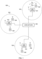
- Figure 1 provides a schematic diagram illustrating some basic functionality of a mobile telecommunications network / system 100 operating generally in accordance with LTE principles, but which may also support other radio access technologies, and which may be adapted to implement embodiments of the disclosure as described herein.
- Various elements of Figure 1 and certain aspects of their respective modes of operation are well-known and defined in the relevant standards administered by the 3GPP (RTM) body, and also described in many books on the subject, for example, Holma H. and Toskala A [2].
- the network 100 includes a plurality of base stations 101 connected to a core network part 102.
- Each base station provides a coverage area 103 (e.g. a cell) within which data can be communicated to and from communications devices 104.
- Data is transmitted from the base stations 101 to the communications devices 104 within their respective coverage areas 103 via a radio downlink.
- Data is transmitted from the communications devices 104 to the base stations 101 via a radio uplink.
- the core network part 102 routes data to and from the communications devices 104 via the respective base stations 101 and provides functions such as authentication, mobility management, charging and so on.
- Communications devices may also be referred to as mobile stations, user equipment (UE), user terminals, mobile radios, terminal devices, and so forth.
- Base stations which are an example of network infrastructure equipment / network access nodes, may also be referred to as transceiver stations / nodeBs / e-nodeBs, g-nodeBs (gNB) and so forth.
- transceiver stations / nodeBs / e-nodeBs, g-nodeBs (gNB) and so forth.
- gNB g-nodeBs
- different terminology is often associated with different generations of wireless telecommunications systems for elements providing broadly comparable functionality.
- example embodiments of the disclosure may be equally implemented in different generations of wireless telecommunications systems such as 5G or new radio as explained below, and for simplicity certain terminology may be used regardless of the underlying network architecture. That is to say, the use of a specific term in relation to certain example implementations is not intended to indicate these implementations are limited to a certain generation of network that may be most associated with that particular terminology.
- FIG. 2 is a schematic diagram illustrating a network architecture for a new RAT wireless communications network / system 200 based on previously proposed approaches which may also be adapted to provide functionality in accordance with embodiments of the disclosure described herein.
- the new RAT network 200 represented in Figure 2 comprises a first communication cell 201 and a second communication cell 202.
- Each communication cell 201, 202 comprises a controlling node (centralised unit) 221, 222 in communication with a core network component 210 over a respective wired or wireless link 251, 252.
- the respective controlling nodes 221, 222 are also each in communication with a plurality of distributed units (radio access nodes / remote transmission and reception points (TRPs)) 211, 212 in their respective cells.
- TRPs remote transmission and reception points
- the distributed units 211, 212 are responsible for providing the radio access interface for communications devices connected to the network.
- Each distributed unit 211, 212 has a coverage area (radio access footprint) 241, 242 where the sum of the coverage areas of the distributed units under the control of a controlling node together define the coverage of the respective communication cells 201, 202.
- Each distributed unit 211, 212 includes transceiver circuitry for transmission and reception of wireless signals and processor circuitry configured to control the respective distributed units 211, 212.
- the core network component 210 of the new RAT communications network represented in Figure 2 may be broadly considered to correspond with the core network 102 represented in Figure 1 , and the respective controlling nodes 221, 222 and their associated distributed units / TRPs 211, 212 may be broadly considered to provide functionality corresponding to the base stations 101 of Figure 1 .
- the term network infrastructure equipment / access node may be used to encompass these elements and more conventional base station type elements of wireless communications systems.
- the responsibility for scheduling transmissions which are scheduled on the radio interface between the respective distributed units and the communications devices may lie with the controlling node / centralised unit and / or the distributed units / TRPs.
- a communications device or UE 260 is represented in Figure 2 within the coverage area of the first communication cell 201. This communications device 260 may thus exchange signalling with the first controlling node 221 in the first communication cell via one of the distributed units 211 associated with the first communication cell 201. In some cases communications for a given communications device are routed through only one of the distributed units, but it will be appreciated in some other implementations communications associated with a given communications device may be routed through more than one distributed unit, for example in a soft handover scenario and other scenarios.
- two communication cells 201, 202 and one communications device 260 are shown for simplicity, but it will of course be appreciated that in practice the system may comprise a larger number of communication cells (each supported by a respective controlling node and plurality of distributed units) serving a larger number of communications devices.
- Figure 2 represents merely one example of a proposed architecture for a new RAT communications system in which approaches in accordance with the principles described herein may be adopted, and the functionality disclosed herein may also be applied in respect of wireless communications systems having different architectures.
- example embodiments of the disclosure as discussed herein may be implemented in wireless telecommunication systems / networks according to various different architectures, such as the example architectures shown in Figures 1 and 2 . It will thus be appreciated the specific wireless communications architecture in any given implementation is not of primary significance to the principles described herein. In this regard, example embodiments of the disclosure may be described generally in the context of communications between network infrastructure equipment / access nodes and a communications device, wherein the specific nature of the network infrastructure equipment / access node and the communications device will depend on the network infrastructure for the implementation at hand.
- the network infrastructure equipment / access node may comprise a base station, such as an LTE-type base station 101 as shown in Figure 1 which is adapted to provide functionality in accordance with the principles described herein, and in other examples the network infrastructure equipment / access node may comprise a control unit / controlling node 221, 222 and / or a TRP 211, 212 of the kind shown in Figure 2 which is adapted to provide functionality in accordance with the principles described herein.
- a base station such as an LTE-type base station 101 as shown in Figure 1 which is adapted to provide functionality in accordance with the principles described herein
- the network infrastructure equipment / access node may comprise a control unit / controlling node 221, 222 and / or a TRP 211, 212 of the kind shown in Figure 2 which is adapted to provide functionality in accordance with the principles described herein.
- the wireless access interface provides physical communications resources including shared channels for both uplink and the downlink which may be accessed by communicating appropriate control signalling as those acquainted with LTE will appreciate.
- FIG. 3 A more detailed illustration of a UE 270 and an example network infrastructure equipment 272, which may be thought of as a gNB 101 or a combination of a controlling node 221 and TRP 211, is presented in Figure 3 .
- the UE 270 is shown to transmit uplink data to the infrastructure equipment 272 via grant free resources of a wireless access interface as illustrated generally by an arrow 274.
- the infrastructure equipment 272 is connected to a core network 276 via an interface 278 to a controller 280 of the infrastructure equipment 272.
- the infrastructure equipment 272 includes a receiver 282 connected to an antenna 284 and a transmitter 286 connected to the antenna 284.
- the UE 270 includes a controller 290 connected to a receiver 292 which receives signals from an antenna 294 and a transmitter 296 also connected to the antenna 294.
- the controller 280 is configured to control the infrastructure equipment 272 and may comprise processor circuitry which may in turn comprise various sub-units / sub-circuits for providing functionality as explained further herein. These sub-units may be implemented as discrete hardware elements or as appropriately configured functions of the processor circuitry. Thus the controller 280 may comprise circuitry which is suitably configured / programmed to provide the desired functionality using conventional programming / configuration techniques for equipment in wireless telecommunications systems.
- the transmitter 286 and the receiver 282 may comprise signal processing and radio frequency filters, amplifiers and circuitry in accordance with conventional arrangements.
- the transmitter 286, the receiver 282 and the controller 280 are schematically shown in Figure 3 as separate elements for ease of representation.
- the functionality of these elements can be provided in various different ways, for example using one or more suitably programmed programmable computer(s), or one or more suitably configured application-specific integrated circuit(s) / circuitry / chip(s) / chipset(s).
- the infrastructure equipment 272 will in general comprise various other elements associated with its operating functionality.
- the controller 290 of the UE 270 is configured to control the transmitter 296 and the receiver 292 and may comprise processor circuitry which may in turn comprise various sub-units / sub-circuits for providing functionality as explained further herein. These sub-units may be implemented as discrete hardware elements or as appropriately configured functions of the processor circuitry.
- the controller 290 may comprise circuitry which is suitably configured / programmed to provide the desired functionality using conventional programming / configuration techniques for equipment in wireless telecommunications systems.
- the transmitter 296 and the receiver 292 may comprise signal processing and radio frequency filters, amplifiers and circuitry in accordance with conventional arrangements.
- the transmitter 296, receiver 292 and controller 290 are schematically shown in Figure 3 as separate elements for ease of representation.
- the functionality of these elements can be provided in various different ways, for example using one or more suitably programmed programmable computer(s), or one or more suitably configured application-specific integrated circuit(s) / circuitry / chip(s) / chipset(s).
- the communications device 270 will in general comprise various other elements associated with its operating functionality, for example a power source, user interface, and so forth, but these are not shown in Figure 3 in the interests of simplicity.
- Enhanced Mobile Broadband (eMBB) services are characterised by high capacity with a requirement to support up to 20 Gb/s.
- the requirements for Ultra Reliable & Low Latency Communications (URLLC) [6] services are for a reliability of 1 - 10 -5 (99.999 %) or higher for one transmission of a 32 byte packet with a user plane latency of 1 ms [3]. In some scenarios, there may be a requirement for a reliability of 1 - 10 -6 (99.9999 %) or higher with either 0.5ms or 1ms of user plane latency.
- Massive Machine Type Communications (mMTC) is another example of a service which may be supported by NR-based communications networks.
- systems may be expected to support further enhancements related to Industrial Internet of Things (IIoT) in order to support services with new requirements of high availability, high reliability, low latency, and in some cases, high-accuracy positioning.
- IIoT Industrial Internet of Things
- Industrial automation, energy power distribution and intelligent transport systems are examples of new use cases for Industrial Internet of Things (IIoT).
- IIoT Industrial Internet of Things
- the system may involve different distributed components working together. These components may include sensors, virtualized hardware controllers and autonomous robots, which may be capable of initiating actions or reacting to critical events occurring within a factory and communicating over a local area network.
- the UEs in the network may therefore be expected to handle a mixture of different traffic, for example, associated with different applications and potentially different quality of service requirements (such as maximum latency, reliability, packet sizes, throughput).
- Some messages for transmission may be time sensitive and be associated with strict deadlines and the communications network may therefore be required to provide time sensitive networking (TSN).
- TSN time sensitive networking
- multiple configured grants/semi-persistent scheduling (SPS) grants may be required in order to provide more flexibility while avoiding excessive dynamic downlink control signalling.
- URLLC being developed for 5G/NR to support IIoT
- One of the aspects of URLLC being developed for 5G/NR to support IIoT is a requirement for URLLC to provide a low latency, measured from the ingress of a layer 2 packet to its egress from the network, with a proposed target of 1 ms with a reliability of 99.999%, and later it has been extended to 0.5ms with a reliability of 99,9999%.
- This is required in order to support the services for IIoT which require high availability, high reliability, low latency, and in some cases, high-accuracy positioning [1].
- one of the requirements for communicating uplink data from a UE is to manage intra-UE packet prioritization and multiplexing. This is a requirement to prioritise the communication of uplink data and control packets from different categories of traffic within the UE.
- Paging permits the transmission downlink data without requiring each communications device 104 to continuously monitor downlink data channels (such as physical downlink shared channels, PDSCHs). Instead, each communications device 104 determines a sequence of time windows, which may be referred as paging frames, during which it monitors a subset of communications resources, such as a paging channel.
- the sequence of time windows or paging frames for each communications device 104 is also known to the infrastructure equipment 101.
- TMSI temporary mobile subscriber identity
- the infrastructure equipment 101 determines that it has downlink data to transmit to the communications device 104, it determines the next paging frame when the communications device 104 will monitor the paging channel.
- the infrastructure equipment 101 may determine that it has downlink data to transmit in response to receiving the downlink data from the core network 102, or based on a generation of data by the infrastructure equipment 101 for transmission to the communications device 104.
- the paging message comprises an indication of an identity of the communications device 104 and an indication that the infrastructure equipment 101 has downlink data for transmission to the communications device 104.
- the communications device 104 In response to receiving the paging message, the communications device 104 transmits a response message to the infrastructure equipment 104. Subsequently, the communications device 104 monitors communications resources on which the infrastructure equipment 101 transmits the downlink data.
- the response message may be transmitted on a random access channel, such as on a physical random access channel (PRACH).
- PRACH physical random access channel
- Different communications devices may be configured with different sets of paging frames, in order to avoid congestion on the paging channel and on the PRACH.
- two or more communications devices select a same instance of the PRACH to transmit a random access request.
- the random access requests may be in response to paging or in response to a determination by the communications device that it has uplink data to transmit.
- the random access request may comprise an element, such as a random access preamble, randomly selected by the communications device.
- Each communications devices selects, at random and independently of the random selection by the other communications device(s), from a number of predetermined RACH preambles.
- their random access requests may still be decoded by the infrastructure equipment if they comprise different preambles.
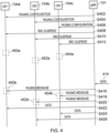
- Figure 4 illustrates a message sequence chart for the transmission of downlink data to multiple communications devices, in accordance with conventional techniques for transmitting downlink data.
- Figure 4 shows three communications devices, UE1 104a, UE2 104b and UE3 104c, and an infrastructure equipment, such as a gNB 101.
- the gNB 101 configures each of UE1 104a, 104b and 104c with a paging configuration.
- the paging configuration permits the communications devices to determine their subsequent paging frames.
- the paging configuration may be carried out while the communications devices are in an RRC connected mode, although the establishment of the RRC connections is not shown for conciseness.
- the paging configuration may comprise an indication of a temporary identifier, such as a TMSI, based on which each UE or communications device (and similarly, the infrastructure equipment 101) is able to determine subsequent paging frames, for example, based on a modulo operation on the TMSI value.
- a temporary identifier such as a TMSI
- the TMSI value and corresponding DRX cycle for monitoring the downlink paging channel may be allocated by the core network; this step is omitted from Figure 4 for conciseness.
- the infrastructure equipment 101 transmits an RRC suspend message to each of the communications device 104a, 104b, 104c, having the effect that the RRC connection for each communications device is suspended.
- the communications devices may thus enter the RRC INACTIVE state from the RRC CONNECTED state.
- state associated with the RRC connection is maintained at the communications devices and the infrastructure equipment.
- the respective RRC connections are not active and the communications devices monitor a paging channel during respective paging frames in accordance with the configuration at steps S402, S404 and S406 to determine if the infrastructure equipment has downlink data for transmission to it. Uplink data cannot be transmitted during the RRC INACTIVE state.
- the RRC INACTIVE state may reduce the requirements on the communications device to monitor downlink communications resources, so that its power consumption is reduced, compared with when in the RRC CONNECTED mode.
- the communications devices 104a, 104b, 104c enter a state in which monitoring requirements are reduced and/or power consumption may be reduced, relative to an active state.
- the new state is the RRC INACTIVE state.
- the communications devices 104a, 104b, 104c monitor the paging channel during their respective paging frames.
- the paging frames shown by dashed rectangles 450, 452, 454
- the three communications devices do not overlap.
- the infrastructure equipment 101 receives downlink data for transmission to the three communications devices 104a, 104b, 104c. In response, it determines the next instance 450b of the paging frames 450 for paging the first communications device 104a, and similarly determines instances 452b and 454b for paging the second and third communications device 104b, 104c.
- the infrastructure equipment 101 transmits paging messages to the first, second and third communications devices 104a, 104b, 104c at steps S416, S420 and S418, respectively.
- the infrastructure equipment transmits the downlink data to the first, second and third communications devices 104a, 104b, 104c, respectively.
- a group of UEs are operating as part of a financial service such as a trading floor and require rapid paging to receive contemporaneously the latest financial information.
- a financial service such as a trading floor and require rapid paging to receive contemporaneously the latest financial information.
- each of the UEs which are configured with a conventional pattern of paging frames which are determined by the UE using the above technique to be re-configured when the UEs are on the trading floor to monitor the same pattern of trading feeds so that a gNB providing a cell serving the trading floor can page all the UEs in the group and therefore transfer down link data more rapidly compared with going to each of the UEs separately as would be the case for a conventional operation in which the UEs determined their paging frames.
- the present disclosure provides a method of operating an infrastructure equipment of a wireless communications network, the method comprising transmitting control information via a wireless access interface provided by the wireless communications network to a communications device to configure the communications device to receive paging messages as part of a group of one or more communications devices, the communications device being configured by the control information from a first state in which the communications device monitors a pattern of paging frames of the wireless access interface for receiving paging messages determined by the communications device to a second state in which the communications device is configured to monitor the same pattern of paging frames of the wireless access interface for receiving paging messages as the group of one or more communications devices.
- Figure 5 illustrates a message sequence chart showing the transmission of downlink data in accordance with embodiments of the present technique.
- the process starts at step S502 with a selection of a group of a plurality of communications devices to receive fast downlink data transmissions.
- the group of communications devices may be selected according to an associated network slice or subscription parameters (for example, that they all subscribe to a certain service, or are associated with a certain commercial entity).
- the communications devices may be selected based on their being associated with a subscription for low latency financial information.
- the financial information may comprise stock exchange prices, or foreign exchange rates, trading information and/or any other similar information.
- location determination is based on measurements of an indoor beacon, device-to-device proximity detection in respect of one or more additional communications devices, and/or radio resource management (RRM) measurements.
- RRM radio resource management
- the communications device may be selected as a group member based on an application associated with (e.g. running on) the communications device.
- the criteria for inclusion in the group may be pre-determined and known to the communications devices. In some embodiments, the criteria are pre-determined at the infrastructure equipment 101 and not at the communications devices.
- first, second and third communications device 104a, 104b and 104c are selected at step S502.
- step S502 and the subsequent configuration steps described below may occur multiple times, such as in response to determining that a communications device 104 has newly satisfied the requirements for selection.
- the infrastructure equipment may determine that a communications device 104 has moved to be within a pre-determined area, such as within a coverage area of the cell 103 controlled by the infrastructure equipment 101.
- the cell 103 may correspond, for example, to a trading floor of a stock exchange.
- the infrastructure equipment 101 may perform step S502 and subsequent configuration steps as described below.
- each of the selected communications devices 104a, 104b, 104c are configured with a same, synchronised, sequence of paging frames by the infrastructure equipment 101.
- the configuration of the synchronised paging frames comprises transmitting to each of the selected communications devices an indication of a value to use in the determination of paging frames, in place of a temporary identifier, such that the paging frames, when determined using each of the values, are the same (i.e. synchronised with respect to each other).
- each value is different; in some embodiments, the same value is used, and in some such embodiments, the value is zero.
- the infrastructure equipment 101 transmits a paging configuration message indicating that the value 0 (zero) is to be used in place of the 5G-S-TMSI (i.e. as the value UE_ID) in determining the paging frames for each of the selected communications devices 104a, 104b, 104c.
- the value is a predetermined value to be used when no temporary identifier has been assigned.
- the configuration of the same paging frames is by assigning each of the selected communications devices with a temporary identifier to use in the determination of paging frames such that the paging frames, when determined using each of the values (for example, in accordance with conventional techniques and/or using equation (1) above), are the same.
- the configuration of the same paging frames is by assigning each of the selected communications devices with a parameter UE ID MOD N to use in the equation (1) in place of the expression ( UE_ID mod N).
- the communications devices 104a, 104b, 104c monitor the downlink paging channel in synchronised paging frames determined in accordance with the configuration at steps S504, S506, S508 described above. All of the selected communications devices 104 which are not in the RRC CONNECTED state monitor the paging channel at the same paging frames. In the example of Figure 5 , these are shown by dashed rectangles at times t1 and t2.
- the infrastructure equipment 101 determines that it has (or will soon receive or generate) downlink data to transmit to each of the communications devices 104a, 104b, 104c in the group. In some embodiments, the same downlink data is to be transmitted to each of the communications devices. In some embodiments, different downlink data is to be transmitted to each of the communications devices.
- the determination at step S516 is based on receiving, while the communications devices are in the RRC INACTIVE state, downlink data from the core network 102.
- the determination is based on generating at the infrastructure equipment 101, downlink data for transmission to the communications devices.
- the determination is based on receiving by the infrastructure equipment 101 a paging message from the core network 102.
- the communications devices 104a, 104b, 104c may be in the RRC IDLE state.
- the infrastructure equipment 101 determines that the next synchronised paging frame to be monitored by the communications devices 104a, 104b, 104c is at time t2.
- the next synchronised paging frame to be monitored by one of the selected communications devices at time t2 will also be monitored by the other selected communications devices.
- the infrastructure equipment 101 transmits in the determined next paging frame a paging message 550.
- the paging message 550 comprises an indication that downlink data is to be transmitted to each of the communications devices 104a, 104b, 104c.
- each of the communications devices 104a, 104b, 104c After receiving the paging message 550, each of the communications devices 104a, 104b, 104c enters the RRC CONNECTED state and receives, at steps S530, S532, and S534, the downlink data 562, 564, 566, respectively.
- the transition from RRC INACTIVE or RRC IDLE to RRC CONNECTED in response to receiving the paging message 550 is automatic, and the communications device enters the RRC CONNECTED mode without additional transmissions.
- each communications device responds to the paging message 550 by transmitting one or more messages before receiving the data, for example in a conventional manner.
- a communications device in response to receiving the paging message 550, transmits a random access message on the PRACH to initiate a random access procedure. The random access procedure results in the establishment or resumption of an RRC connection, and the subsequent reception of the downlink data.
- one or more of the selected communications devices performs a random access procedure prior to receiving the downlink data, and one or more of the selected communications devices enters the RRC CONNECTED state automatically.
- the infrastructure equipment 101 may transmit (for example, as part of the configuration steps S504, S506, S508) a random access permission indication to each of the selected communications devices to indicate that one of the following applies to the communications device:
- the random access permission indication indicates that the communications device is required to initiate a random access procedure
- the random access permission indication may further indicate that the communications device is to perform a 4-step RACH or a 2-step RACH procedure.
- each communications device may proceed in accordance with the configuration.
- the infrastructure equipment 101 configures exactly one of the selected communications devices to be required to initiate a random access procedure in response to a paging message transmitted during a synchronised paging frame.
- the first communications device 104a responds to the paging message 550 by initiating a 4-step RACH procedure by transmitting, at step S520, a random access message 552 on the PRACH.
- the infrastructure equipment 101 transmits a random access response 554 at step S522.
- the communications device 104a transmits a ⁇ message 3', such as an RRC Resume request message 556.
- the infrastructure equipment 101 transmits an RRC Resume message 558 in response to receiving the RRC Resume request message 556.
- the communications device 104a transmits an RRC Resume Complete message 560.
- the communications device 104a enters RRC CONNECTED state.
- the first communications device 104a therefore receives the data 562 in step S530.
- the second and third communications devices 104b, 104c are configured to enter the RRC CONNECTED state without completing a random access procedure.
- they enter the RRC CONNECTED state and, at steps S532 and S534, receive the data 564, 566 without completing a random access procedure. Details of this step are provided below.
- the second and third communications devices 104b, 104c may enter the RRC CONNECTED mode directly in response to receiving the paging message 550, and may thus receive the data 564, 566 earlier than is shown in the sequence of Figure 5 . For example, they may receive the data prior to the completion of the random access procedure of the first communications device 104a.
- the process of Figure 5 may be repeated for different selected groups of communications devices.
- the steps of the process of Figure 5 may be repeated in respect of a given communications device, whereby different synchronised paging frames may be configured for different selected groups to which the communications device belongs, or for different traffic types (for example, for downlink data having different quality of service requirements, or associated with different services).
- one or more of the communications devices 104a, 104b, 104c may enter the RRC CONNECTED state directly in response to receiving the paging message 550.
- one or more of the communications devices 104a, 104b, 104c may have been in a first state in which they were configured with paging frames which are not synchronised with those of the other selected communications devices. This may be, for example, prior to step S502.
- the non-synchronised paging frames may have been configured in accordance with conventional techniques, such as those illustrated in Figure 4 and described above, for example, based on the assigned 5G-S-TMSI, when the 5G-S-TMSI is assigned in a manner which does not ensure synchronised paging frames for the selected communications devices.
- the communications devices may enter a second state in which the synchronised paging frames are configured.
- a communications device may be configured only in the second state by means of one of the steps S504, S506, S508 if, for example, on initial connection to the wireless communications network (such as after being switched on or reset) it is determined to satisfy the criteria for being configured in the second state.
- the synchronised paging frames are used for all paging message for the communications devices and as such, replace any non-synchronised paging frames. Therefore, in the second state, the communications device 104 may monitor only synchronised paging frames.
- the synchronised paging frames are configured in addition to non-synchronised paging frames.
- the communications device 104 may monitor synchronised paging frames and non-synchronised paging frames.
- the infrastructure equipment 101 may determine, in such embodiments, whether to page the communications devices within the selected group using a synchronised paging frame, or a non-synchronised paging frame. This determination may be based on a latency requirement associated with the downlink data (so that, downlink data having a maximum permitted latency below a predetermined threshold is notified using a synchronised paging frame). Additionally or alternatively, the determination may be based on whether application data is to be transmitted only to a single communications device, or to all communications devices within the selected group.
- the infrastructure equipment may use a next synchronised paging frame. This may ensure that the data is transmitted with improved (i.e. lower) latency and/or making more efficient use of the communications resources of the wireless access interface to all communications devices, collectively, compared with using conventional paging techniques for each communications device.
- the configuration of the synchronised paging frames is carried out separately from the suspension of the RRC connections.
- these steps may be combined. That is, for example, at step S514 in which the infrastructure equipment 101 transmits to the first communications device 104a a message indicating that the RRC connection is to be suspended or released, the same message may also comprise an indication of the synchronised paging frames, such as an indication of the temporary identifier as described above.
- steps S504 and S514 may be combined, steps S506 and S512 may be combined and/or steps S508 and S510 may be combined.
- the infrastructure equipment 101 may, in addition, indicate to the respective communications device 104 whether, in response to subsequently receiving a paging message, one or both of a random access (RACH) procedure and/or an RRC Resume/RRC establishment procedure are to be skipped prior to the RRC connection being established or resumed.
- RACH random access
- the selected plurality of communications devices may comprise all communications devices currently having the same serving cell.
- access to a particular cell may be restricted a priori to communications devices within the selected group, for example, based on an associated subscription.
- the infrastructure equipment 101 may be provided for the exclusive use of employees at a particular company, or participants in a particular activity at a particular location (for example, traders at a stock market). Each communications device associated with such employees or participants may be associated with a subscription (known to the wireless communications network) permitting the communications device to access a cell provided by the infrastructure equipment 101.
- the configuration of the synchronised paging frames may be by means of a broadcast transmission by the infrastructure equipment 101.
- the broadcast transmission may indicate a UE ID value for use in a conventional paging frame calculation technique, such as in accordance with equation (1) above.
- the broadcast transmission may be a system information message transmitted on a broadcast channel.
- the infrastructure equipment 101 may additionally or alternatively indicate whether the respective communications device 104a, 104b, 104c is to monitor the synchronised paging frames, paging frames determined in a conventional manner, or both.
- the infrastructure equipment 101 may subsequently transmit paging messages to a communications device in one or more paging frames which the respective communications device has been indicated to monitor in step S504, S506 or S508.
- a communications device may transmit a synchronised paging capability indication to the infrastructure equipment that indicates that the communications device is capable of being configured to monitor synchronised paging frames.
- the synchronised paging capability may indicate that the communications device will, in response to the configuration described at steps S504, S506 or S508 above, monitor the synchronised paging frames at t1 and t2, as described above.
- the communications device 104 may also indicate its capability to skip the RACH procedure and/or the RRC Resume/Establishment procedure in response to receiving the paging message.
- all of the selected group of communications devices 104 are in the RRC INACTIVE state when the infrastructure equipment 101 determines that there is downlink data to send at step S516.
- the infrastructure equipment 101 may determine for which of the selected group of communications devices 104 there is data to be transmitted, and of those, which state each is in.
- the selected group of communications devices may comprise the three communications devices 104a, 104b, 104c as well as one or more additional communications devices.
- the infrastructure equipment may determine that each of the additional communications devices are either in the RRC CONNECTED state (in which case the data may be transmitted using conventional techniques for downlink data transmission during RRC CONNECTED state), or there may be no data to be transmitted to that communications device.
- the infrastructure equipment 101 may transmit the data to the three communications devices illustrated in Figure 5 as described above.
- the infrastructure equipment may treat communications devices in the RRC IDLE mode in the same manner as communications devices in the RRC INACTIVE state. In some embodiments, the infrastructure equipment may transmit separate paging message to communications devices in the RRC IDLE state and to communications devices in RRC INACTIVE state.
- the same data may be for transmission to all communications devices in the selected group, in which case the determination may be made only in respect of the RRC state of each device in the group.
- Figure 6 is a message sequence chart showing a transmission of downlink data in accordance with embodiments of the present technique.
- none of the three communications devices 104a, 104b, 104c are in the RRC CONNECTED state.
- all three may be in the RRC INACTIVE state or in the RRC IDLE state.
- some or all of the steps S502 to S514 as shown in Figure 5 and described above may have occurred prior to the sequence shown in Figure 5 .
- At least the second and third communications devices 104b, 104c are configured to monitor via a receiver for a wake-up trigger message, which may be transmitted by another communications device.
- the configuration may comprise determining a nature (e.g. modulation scheme, message contents, encoding) of the wake-up trigger message, and means for its transmission (e.g. carrier frequency, schedule of possible time(s) of transmission).
- a nature e.g. modulation scheme, message contents, encoding
- means for its transmission e.g. carrier frequency, schedule of possible time(s) of transmission
- the periodicity of potential times of transmission of the wake-up trigger message is smaller than that of the non-synchronised paging frame occurrences monitored by the second and/or third communications devices 104b, 104c.
- the potential times of transmission of the wake-up trigger are aperiodic.
- the wake-up trigger message is transmitted by the communications device 104a multiple times in response to a trigger event (e.g. the receipt of the paging message 750).
- the multiple transmissions may be in accordance with a predetermined rule known to both the first communications device 104a and the other communications devices 104b, 104c.
- At least the first communications device 104a is configured with (i.e. determines) the nature and means for transmission for the wake-up trigger message.
- the configuration is by means of the transmission by the infrastructure equipment 101 and receipt by the communications device 104 of a configuration message, such as the messages transmitted in step S504-S508 described above.
- the first communications device 104a is monitoring paging frames which are not synchronised with those of the other communications devices 104b, 104c.
- the paging frame occurrence 450c may be determined based on an assigned TMSI, as described above in the example of Figure 4 .
- the monitoring of the non-synchronised paging frames may be in addition to the monitoring of the synchronised paging frames.
- steps S504-S508 are omitted, such that each communications device 104 is configured to monitor only non-synchronised paging frames, for example in accordance with conventional techniques.
- the infrastructure equipment receives data from the core network 102 (not shown) for transmission to the three communications devices 104a, 104b, 104c. It will be appreciated, as described above, that the downlink data may also be generated by the infrastructure equipment 101.
- the infrastructure equipment 101 determines the next paging frame to be monitored by any of the communications devices 104a, 104b, 104c. In the example of Figure 6 , this is determined to be the paging frame occurrence 450c being monitored by the first communications device 104a.
- the infrastructure equipment 101 transmits a paging message 750 to the first communications device 104a, such that it is received within the paging frame occurrence 450c.
- the paging message 750 comprises an indication that the infrastructure equipment 101 has downlink data to be transmitted to each of the three communications devices 104a, 104b, 104c. Alternatively, in some embodiments, the paging message 750 may indicate simply that the infrastructure equipment 101 has downlink data to be transmitted to at least one communications device in addition to the first communications device 104a.
- the first communications devices 104a transmits, at step S706, a wake-up trigger message 752. This is received by the second and third communications devices 104b, 104c.
- the second and third communications devices 104b, 104c leave the RRC INACTIVE state.
- the second and third communications devices 104b, 104c may perform either
- the second and third communications devices 104b, 104c may then monitor a downlink channel for a transmission of data by the infrastructure equipment 101.
- the infrastructure equipment 101 may decide to omit the random access procedure if, for example, time alignment does not change compared to previous RA procedure. This may be because, for example, one or both of the communications devices 104b, 104c are stationary.
- the infrastructure equipment 101 may configure one or both of the communications devices 104b, 104c to skip an RRC Resume procedure if infrastructure equipment 101 determines that there is no security risk associated with such a modified procedure for this UE and authentication token/ new key generation is not required.
- the infrastructure equipment 101 transmits the data 754 to the first, second and third communications devices 104a, 104b, 104c.
- each of the communications devices may carry out a procedure to request the resumption or establishment of an RRC connection with the infrastructure equipment 101, for example by means of a 4-step or 2-step RACH procedure.
- a single transmission is made at step S708 of the data 754.
- the data 754 is transmitted in one or more separate messages, each to one or more of the communications devices.
- a communications device 104 in response to a paging message, performs a random access procedure in order to request establishment or resumption of an RRC connection, for example as illustrated in steps S520 to S528 of Figure 5 , and described above.
- One use of a RACH procedure is to determine a timing advance for uplink transmissions by the communications device.
- the communications devices 104 determines that a timing advance determined while the RRC connection was active (i.e. not suspended) is still valid, based on a determination that a distance moved by the communications device 104 since the timing advance was previously determined to be valid is less than a predetermined threshold.
- a communications device 104 in response to determining that the previous timing advance is still valid, then, in response to a paging message, a communications device 104 performs an uplink transmission using the previous timing advance.
- the uplink transmission may be on communications resources of an uplink shared channel of the wireless access interface.
- the uplink transmission may comprise a ⁇ message 3' (i.e., a message which may be the third message sent in a conventional random access procedure), such as the RRC Resume Request 556, transmitted at step S524 as described above.
- a ⁇ message 3' i.e., a message which may be the third message sent in a conventional random access procedure
- the uplink transmission may be in accordance with further parameters configured prior to the suspension of the RRC connection.
- the communications device 104 may receive, while the RRC connection is active, or as part of the suspension of the RRC connection, an indication of allocated communications resources, from which the communications resources for the uplink transmission may be selected.
- the allocated communications resources comprise a configured grant (CG) or grant free' resources.
- CG or grant free resources are a set of periodically repeating uplink communications resources which are semi-statically configured by the network for the use of the communications device for uplink transmission.
- the allocated communications resources are periodic having a periodicity such that the transmission of the uplink message using the allocated communications resources may occur before the transmission of the ⁇ message 3' of a conventional random access procedure comprising a random access transmission on the PRACH.
- the periodicity of the allocated communications resources i.e. the time duration between consecutive instances of the allocated communications resources
- the periodicity of the allocated communications resources is lower than a time duration between the reception of a paging message and an earliest opportunity for a subsequent transmission of a ⁇ message 3'.
- steps and features described herein may be combined in ways other than described above. In some embodiments, steps and features may be combined with or replace those of conventional techniques.
- a method of operating an infrastructure equipment of a wireless communications network comprising transmitting control information via a wireless access interface provided by the wireless communications network to a communications device to configure the communications device to receive paging messages as part of a group of one or more communications devices, the communications device being configured by the control information from a first state in which the communications device monitors a pattern of paging frames of the wireless access interface for receiving paging messages determined by the communications device to a second state in which the communications device is configured to monitor the same pattern of paging frames of the wireless access interface for receiving paging messages as the group of one or more communications devices.
- predetermined / predefined information may in general be established, for example, by definition in an operating standard for the wireless telecommunication system, or in previously exchanged signalling between the base station and communications devices, for example in system information signalling, or in association with radio resource control setup signalling, or in information stored in a SIM application. That is to say, the specific manner in which the relevant predefined information is established and shared between the various elements of the wireless telecommunications system is not of primary significance to the principles of operation described herein.
Landscapes
- Engineering & Computer Science (AREA)
- Computer Networks & Wireless Communication (AREA)
- Signal Processing (AREA)
- Mobile Radio Communication Systems (AREA)
Applications Claiming Priority (3)
| Application Number | Priority Date | Filing Date | Title |
|---|---|---|---|
| EP19158952 | 2019-02-22 | ||
| EP20700407.8A EP3928569B1 (de) | 2019-02-22 | 2020-01-16 | Kommunikationsvorrichtung, infrastrukturausrüstung und verfahren |
| PCT/EP2020/050984 WO2020169279A1 (en) | 2019-02-22 | 2020-01-16 | Communications device, infrastructure equipment and methods |
Related Parent Applications (1)
| Application Number | Title | Priority Date | Filing Date |
|---|---|---|---|
| EP20700407.8A Division EP3928569B1 (de) | 2019-02-22 | 2020-01-16 | Kommunikationsvorrichtung, infrastrukturausrüstung und verfahren |
Publications (2)
| Publication Number | Publication Date |
|---|---|
| EP4444000A2 true EP4444000A2 (de) | 2024-10-09 |
| EP4444000A3 EP4444000A3 (de) | 2025-01-15 |
Family
ID=65529589
Family Applications (2)
| Application Number | Title | Priority Date | Filing Date |
|---|---|---|---|
| EP20700407.8A Active EP3928569B1 (de) | 2019-02-22 | 2020-01-16 | Kommunikationsvorrichtung, infrastrukturausrüstung und verfahren |
| EP24193880.2A Withdrawn EP4444000A3 (de) | 2019-02-22 | 2020-01-16 | Kommunikationsvorrichtung, infrastrukturausrüstung und verfahren |
Family Applications Before (1)
| Application Number | Title | Priority Date | Filing Date |
|---|---|---|---|
| EP20700407.8A Active EP3928569B1 (de) | 2019-02-22 | 2020-01-16 | Kommunikationsvorrichtung, infrastrukturausrüstung und verfahren |
Country Status (4)
| Country | Link |
|---|---|
| US (1) | US12127162B2 (de) |
| EP (2) | EP3928569B1 (de) |
| CN (1) | CN113383587A (de) |
| WO (1) | WO2020169279A1 (de) |
Families Citing this family (2)
| Publication number | Priority date | Publication date | Assignee | Title |
|---|---|---|---|---|
| CN111836361B (zh) * | 2019-08-12 | 2022-06-17 | 维沃移动通信有限公司 | 数据接收方法、发送方法、终端及网络设备 |
| TWI900622B (zh) * | 2020-10-05 | 2025-10-11 | 日商索尼集團公司 | 通訊裝置,基礎建設設備及方法 |
Citations (1)
| Publication number | Priority date | Publication date | Assignee | Title |
|---|---|---|---|---|
| GB2509071A (en) | 2012-12-19 | 2014-06-25 | Sony Corp | Allocating radio resources for uplink data |
Family Cites Families (13)
| Publication number | Priority date | Publication date | Assignee | Title |
|---|---|---|---|---|
| EP2369890A1 (de) | 2010-03-26 | 2011-09-28 | Panasonic Corporation | Verbindungsspitzenvermeidung für MTC-Vorrichtungen |
| CN102469585A (zh) | 2010-11-09 | 2012-05-23 | 中兴通讯股份有限公司 | 一种对mtc组进行寻呼的方法及系统 |
| CN102625254B (zh) | 2011-01-31 | 2015-12-02 | 华为技术有限公司 | 分组寻呼的方法、装置及系统 |
| CN103444248B (zh) | 2011-02-14 | 2017-12-26 | 诺基亚通信公司 | 寻呼控制方法和装置 |
| US8989741B2 (en) | 2011-05-23 | 2015-03-24 | Interdigital Patent Holdings, Inc. | Apparatus and methods for group wireless transmit/receive unit (WTRU) handover |
| US9451651B2 (en) * | 2011-10-12 | 2016-09-20 | At&T Mobility Ii Llc | Management of multiple radio access bearer sessions in communication system |
| US8811989B2 (en) | 2011-10-21 | 2014-08-19 | Lg Electronics Inc. | Method and apparatus for transmitting paging message for M2M device in wireless communication system |
| IN2014CN02783A (de) | 2011-11-04 | 2015-07-03 | Intel Corp | |
| CN103517414A (zh) | 2012-06-26 | 2014-01-15 | 中兴通讯股份有限公司 | 机器类型通信用户设备的寻呼方法及装置 |
| US10225698B2 (en) * | 2014-07-03 | 2019-03-05 | Cisco Technology, Inc. | System and method for providing message delivery and paging to a group of users in a network environment |
| WO2016190711A1 (en) * | 2015-05-27 | 2016-12-01 | Samsung Electronics Co., Ltd. | Method of managing indication of coverage extension (ce) level |
| KR102064930B1 (ko) | 2017-02-09 | 2020-01-13 | 한국전자통신연구원 | 그룹 아이디를 이용한 멀티캐스팅 전송 방법 및 장치 |
| WO2019033112A1 (en) * | 2017-08-11 | 2019-02-14 | Intel Corporation | ALARM SIGNALING IN WIRELESS TELECOMMUNICATION NETWORKS |
-
2020
- 2020-01-16 CN CN202080012073.6A patent/CN113383587A/zh active Pending
- 2020-01-16 EP EP20700407.8A patent/EP3928569B1/de active Active
- 2020-01-16 US US17/430,731 patent/US12127162B2/en active Active
- 2020-01-16 EP EP24193880.2A patent/EP4444000A3/de not_active Withdrawn
- 2020-01-16 WO PCT/EP2020/050984 patent/WO2020169279A1/en not_active Ceased
Patent Citations (1)
| Publication number | Priority date | Publication date | Assignee | Title |
|---|---|---|---|---|
| GB2509071A (en) | 2012-12-19 | 2014-06-25 | Sony Corp | Allocating radio resources for uplink data |
Non-Patent Citations (2)
| Title |
|---|
| "Revised SID: Study on NR Industrial Internet of Things (IoT", RP-182090 |
| HOLMA H.TOSKALA A: "LTE for UMTS OFDMA and SC-FDMA based radio access", 2009, JOHN WILEY AND SONS |
Also Published As
| Publication number | Publication date |
|---|---|
| EP3928569B1 (de) | 2024-09-11 |
| US20220141801A1 (en) | 2022-05-05 |
| EP3928569A1 (de) | 2021-12-29 |
| CN113383587A (zh) | 2021-09-10 |
| US12127162B2 (en) | 2024-10-22 |
| WO2020169279A1 (en) | 2020-08-27 |
| EP4444000A3 (de) | 2025-01-15 |
Similar Documents
| Publication | Publication Date | Title |
|---|---|---|
| US10674380B2 (en) | On-demand system information for wireless terminal in connected state | |
| US12550018B2 (en) | Communications device, communications nodes in a wireless communicaitons network and methods | |
| US9432914B2 (en) | Device-to-device communication | |
| EP2515597B1 (de) | Verfahren zur zeitplanung drahtloser ressourcen, netzwerkelement eines zugriffsnetzwerks und endgerät damit | |
| US20190014538A1 (en) | Broadcast twt indication in broadcast probe response and fils discovery frames to aid unassociated stas | |
| US11012845B2 (en) | Device-to-device discovery communication | |
| US9794936B2 (en) | Multireceiver timing advance provisioning | |
| CN105578382B (zh) | 资源的获取、配置方法及装置,资源池的配置方法及装置 | |
| US12069525B2 (en) | Communications device, infrastructure equipment and methods | |
| US12317328B2 (en) | Method and apparatus for switching of data transmission between radio access technologies for early data transmission | |
| US20250106820A1 (en) | Communications device, infrastructure equipment, core network part and methods | |
| KR102163480B1 (ko) | 단말 간 직접 통신에서 탐색 자원 할당을 위한 단말 간 스케줄링 방법 및 그 장치 | |
| US10362580B2 (en) | Fair resource sharing in broadcast based D2D communications | |
| EP3928569B1 (de) | Kommunikationsvorrichtung, infrastrukturausrüstung und verfahren | |
| US12213154B2 (en) | Communications device, infrastructure equipment and methods for the reception of control information by a communications device in a wireless communications network | |
| US10462803B2 (en) | Control signaling for device to device communication | |
| EP3163976B1 (de) | Basisstationsvorrichtung, mobilstationsvorrichtung, funkkommunikationssystem, kommunikationssteuerungsverfahren einer basisstationsvorrichtung und kommunikationssteuerungsverfahren für eine mobilstationsvorrichtung | |
| US9374820B2 (en) | Dynamic temporary block flow scheduling | |
| US10582390B2 (en) | Method and apparatus for cooperative communication in wireless communication system | |
| US20240147506A1 (en) | Dynamic sl resource allocation | |
| GB2643127A (en) | Method, apparatus and computer program |
Legal Events
| Date | Code | Title | Description |
|---|---|---|---|
| PUAI | Public reference made under article 153(3) epc to a published international application that has entered the european phase |
Free format text: ORIGINAL CODE: 0009012 |
|
| STAA | Information on the status of an ep patent application or granted ep patent |
Free format text: STATUS: REQUEST FOR EXAMINATION WAS MADE |
|
| 17P | Request for examination filed |
Effective date: 20240826 |
|
| AC | Divisional application: reference to earlier application |
Ref document number: 3928569 Country of ref document: EP Kind code of ref document: P |
|
| AK | Designated contracting states |
Kind code of ref document: A2 Designated state(s): AL AT BE BG CH CY CZ DE DK EE ES FI FR GB GR HR HU IE IS IT LI LT LU LV MC MK MT NL NO PL PT RO RS SE SI SK SM TR |
|
| PUAL | Search report despatched |
Free format text: ORIGINAL CODE: 0009013 |
|
| AK | Designated contracting states |
Kind code of ref document: A3 Designated state(s): AL AT BE BG CH CY CZ DE DK EE ES FI FR GB GR HR HU IE IS IT LI LT LU LV MC MK MT NL NO PL PT RO RS SE SI SK SM TR |
|
| RIC1 | Information provided on ipc code assigned before grant |
Ipc: H04W 76/27 20180101ALI20241212BHEP Ipc: H04W 68/02 20090101AFI20241212BHEP |
|
| STAA | Information on the status of an ep patent application or granted ep patent |
Free format text: STATUS: THE APPLICATION HAS BEEN WITHDRAWN |
|
| 18W | Application withdrawn |
Effective date: 20250218 |
|
| RAP3 | Party data changed (applicant data changed or rights of an application transferred) |
Owner name: SONY GROUP CORPORATION Owner name: SONY EUROPE B.V. |