EP4443708A1 - Rotor and magnetic wave gear device - Google Patents
Rotor and magnetic wave gear device Download PDFInfo
- Publication number
- EP4443708A1 EP4443708A1 EP21966358.0A EP21966358A EP4443708A1 EP 4443708 A1 EP4443708 A1 EP 4443708A1 EP 21966358 A EP21966358 A EP 21966358A EP 4443708 A1 EP4443708 A1 EP 4443708A1
- Authority
- EP
- European Patent Office
- Prior art keywords
- rotor
- magnet
- stator
- magnetic
- base
- Prior art date
- Legal status (The legal status is an assumption and is not a legal conclusion. Google has not performed a legal analysis and makes no representation as to the accuracy of the status listed.)
- Pending
Links
Images


Classifications
-
- H—ELECTRICITY
- H02—GENERATION; CONVERSION OR DISTRIBUTION OF ELECTRIC POWER
- H02K—DYNAMO-ELECTRIC MACHINES
- H02K1/00—Details of the magnetic circuit
- H02K1/06—Details of the magnetic circuit characterised by the shape, form or construction
- H02K1/22—Rotating parts of the magnetic circuit
- H02K1/27—Rotor cores with permanent magnets
- H02K1/2706—Inner rotors
- H02K1/272—Inner rotors the magnetisation axis of the magnets being perpendicular to the rotor axis
- H02K1/274—Inner rotors the magnetisation axis of the magnets being perpendicular to the rotor axis the rotor consisting of two or more circumferentially positioned magnets
- H02K1/2753—Inner rotors the magnetisation axis of the magnets being perpendicular to the rotor axis the rotor consisting of two or more circumferentially positioned magnets the rotor consisting of magnets or groups of magnets arranged with alternating polarity
- H02K1/278—Surface mounted magnets; Inset magnets
-
- H—ELECTRICITY
- H02—GENERATION; CONVERSION OR DISTRIBUTION OF ELECTRIC POWER
- H02K—DYNAMO-ELECTRIC MACHINES
- H02K49/00—Dynamo-electric clutches; Dynamo-electric brakes
- H02K49/10—Dynamo-electric clutches; Dynamo-electric brakes of the permanent-magnet type
- H02K49/102—Magnetic gearings, i.e. assembly of gears, linear or rotary, by which motion is magnetically transferred without physical contact
-
- H—ELECTRICITY
- H02—GENERATION; CONVERSION OR DISTRIBUTION OF ELECTRIC POWER
- H02K—DYNAMO-ELECTRIC MACHINES
- H02K16/00—Machines with more than one rotor or stator
- H02K16/02—Machines with one stator and two or more rotors
-
- H—ELECTRICITY
- H02—GENERATION; CONVERSION OR DISTRIBUTION OF ELECTRIC POWER
- H02K—DYNAMO-ELECTRIC MACHINES
- H02K2213/00—Specific aspects, not otherwise provided for and not covered by codes H02K2201/00 - H02K2211/00
- H02K2213/12—Machines characterised by the modularity of some components
-
- Y—GENERAL TAGGING OF NEW TECHNOLOGICAL DEVELOPMENTS; GENERAL TAGGING OF CROSS-SECTIONAL TECHNOLOGIES SPANNING OVER SEVERAL SECTIONS OF THE IPC; TECHNICAL SUBJECTS COVERED BY FORMER USPC CROSS-REFERENCE ART COLLECTIONS [XRACs] AND DIGESTS
- Y02—TECHNOLOGIES OR APPLICATIONS FOR MITIGATION OR ADAPTATION AGAINST CLIMATE CHANGE
- Y02T—CLIMATE CHANGE MITIGATION TECHNOLOGIES RELATED TO TRANSPORTATION
- Y02T10/00—Road transport of goods or passengers
- Y02T10/60—Other road transportation technologies with climate change mitigation effect
- Y02T10/64—Electric machine technologies in electromobility
Definitions
- the present disclosure relates to a rotor and a magnetic wave gear device.
- the magnetic wave gear device As an electric generator of a wind power generation device, a magnetic wave gear device obtained by integrating a magnetic speed reducer and a rotating machine has been known.
- the magnetic wave gear device includes a low-speed rotor, a high-speed rotor provided coaxially with the low-speed rotor, and a stator including a stator winding and a permanent magnet.
- the magnetic wave gear device can change the rotation speed of the rotor in a non-contact manner, without using a mechanical transmission in which mechanical wear occurs.
- the load of maintenance for mechanical wear is reduced.
- speed change and power generation are possible with one device, and thus the size of an electric generation system is reduced and space saving can be achieved.
- a magnetic wave gear device in which a stator having a plurality of permanent magnets, a high-speed rotor having a plurality of rotor magnets, and a low-speed rotor having a plurality of magnet pieces are concentrically arranged, is disclosed (e.g., see Patent Document 1).
- a stator having a plurality of permanent magnets e.g., a stator having a plurality of permanent magnets
- a high-speed rotor having a plurality of rotor magnets, and a low-speed rotor having a plurality of magnet pieces are concentrically arranged is disclosed (e.g., see Patent Document 1).
- a rotor in which a plurality of magnet modules obtained by fixing rotor magnets to bases are arranged in the circumferential direction can be used.
- a rotor in which the base of the magnet module is formed of a magnetic material is disclosed (e.g., see Patent Document 2).
- a boundary between the magnet modules is a boundary between adjacent magnetic poles, and thus the magnetic resistance between the magnetic poles is high. Therefore, even if the conventional rotor is applied to the magnetic wave gear device, the magnetic resistance between the magnetic poles of the rotor is high, thus causing a problem that the output is low.
- the present disclosure has been made to solve the above problem, and an object of the present disclosure is to provide a rotor having low magnetic resistance between the magnetic poles.
- a rotor of the present disclosure includes magnet modules arranged in an annular shape with a rotary shaft as a center.
- Each magnet module includes a base formed of a magnetic material, and two rotor magnets having poles different from each other and provided with a gap therebetween in the rotation direction of the rotary shaft on an outer circumferential surface of the base.
- the rotor magnets abutting each other of two said magnet modules adjacent in the rotation direction have the same pole and are in close contact with each other.
- the abutting rotor magnets of the two magnet modules adjacent in the rotation direction have the same pole and are in close contact with each other, so that the magnetic resistance between the magnetic poles can be reduced.
- FIG. 1 is a front view of a magnetic wave gear device according to embodiment 1.
- a magnetic wave gear device 1 of the present embodiment has a cylindrical frame 2, a stator 3, a low-speed rotor 4, and a high-speed rotor 5.
- the stator 3 includes a stator core 31 which has a plurality of slots disposed in the circumferential direction, stator windings 32 provided in the slots, and stator magnets 33.
- the stator 3 is fixed to the frame 2, on an inner circumferential side of the frame 2.
- the low-speed rotor 4 has a cylindrical low-speed rotor core provided with a gap on an inner circumferential side of the stator 3.
- the high-speed rotor 5 is concentric with a rotary shaft 41 of the low-speed rotor 4, and is provided with a gap on an inner circumferential side of the low-speed rotor core.
- the high-speed rotor 5 includes a cylindrical high-speed rotor core 51, and magnet modules 52 disposed so as to be arranged in the circumferential direction.
- the low-speed rotor 4 includes a low-speed rotor end plate 42 which fastens the low-speed rotor core and the rotary shaft 41 on an outer side of the high-speed rotor 5 in a direction of the rotary shaft 41.
- the low-speed rotor end plate 42 of the present embodiment includes a plurality of spokes 42a. Openings are formed between the plurality of spokes 42a.
- FIG. 2 is a perspective view of the magnet module according to the present embodiment.
- a direction indicated by a double-sided arrow is the rotation direction of the rotary shaft 41 of the magnetic wave gear device 1 shown in FIG. 1 .
- Each magnet module 52 includes a base 6, and two rotor magnets 7, 8 having poles different from each other and provided with a gap therebetween in the rotation direction on an outer circumferential surface of the base 6.
- the base 6 is formed of a plurality of electromagnetic steel sheets 61 stacked in the axial direction of the rotary shaft.
- the plurality of electromagnetic steel sheets 61 are fixed by a bottom plate 62 having an L-shaped cross-section, an end plate 63, and fixing bolts 64.
- the two rotor magnets 7, 8 have poles different from each other. For example, when an outer circumferential side of the rotor magnet 7 is an N pole, an outer circumferential side of the rotor magnet 8 is an S pole. As shown in FIG. 2 , the two rotor magnets 7, 8 are each bisected in the rotation direction and in the axial direction, to form four magnet pieces. The magnet pieces are firmly fixed to the base 6 by, for example, an adhesive.
- FIG. 3 is a cross-sectional view of a high-speed rotor according to the present embodiment.
- the high-speed rotor 5 according to the present embodiment includes the magnet modules 52 arranged in close contact so as to form an annular shape on an outer circumferential surface of the cylindrical high-speed rotor core 51.
- FIG. 3 shows a part of a cross-section of the high-speed rotor 5 in which the magnet modules 52 are disposed in the rotation direction of the rotary shaft 41.
- a direction indicated by a double-sided arrow is the rotation direction of the rotary shaft 41 of the magnetic wave gear device 1 shown in FIG. 1 .
- FIG. 3 As shown in FIG.
- the abutting rotor magnets of the magnet modules 52 adjacent in the rotation direction have the same pole and are in close contact with each other.
- one magnetic pole is located across two magnet modules 52.
- broken lines indicate boundaries between magnetic poles.
- the N-pole rotor magnet 7 on the left side of the magnet module 52a disposed at the center and the N-pole rotor magnet 8 on the right side of the magnet module 52b disposed on the left side form one N-pole magnetic pole.
- the S-pole rotor magnet 8 on the right side of the magnet module 52a disposed at the center and the S-pole rotor magnet 7 on the left side of the magnet module 52c disposed on the right side form one S-pole magnetic pole.
- each boundary between the magnetic poles is located at a center part of the magnet module.
- the base of the magnet module serves as a magnetic path between the magnetic poles, thereby decreasing the magnetic resistance between the magnetic poles.
- the base of the magnet module is formed of the electromagnetic steel sheets stacked in the axial direction, a current route in the axial direction is split, so that it becomes difficult for eddy current to flow.
- eddy current loss due to harmonic magnetic flux can be reduced.
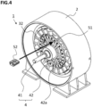
- FIG. 4 is a perspective view of the magnetic wave gear device according to the present embodiment.
- the low-speed rotor end plate 42 includes the plurality of spokes 42a. Openings are formed between the spokes 42a.
- the magnet module 52 can also be disposed through the opening onto the outer circumferential surface of the high-speed rotor core 51. In the case where the high-speed rotor is assembled as described above, when the high-speed rotor core 51 is inserted to the inner circumferential side of the stator 3, the rotor magnets 7, 8 have not been assembled in the high-speed rotor core 51.
- the base of the magnet module is formed of the stacked electromagnetic steel sheets.
- the base of the magnet module may be an integrated magnetic material.
- the two rotor magnets 7, 8 are each bisected in the rotation direction and in the axial direction, to form the four magnet pieces.
- the rotor magnets 7, 8 are divided into the magnet pieces, it becomes difficult for eddy current due to a harmonic magnetic flux to flow and eddy current loss in the rotor magnets 7, 8 can be reduced.
- each of the rotor magnets 7, 8 may be composed of one magnet.
- the base of the magnet module As the base of the magnet module, the base in which the plurality of electromagnetic steel sheets are stacked is used. In embodiment 2, as the base of the magnet module, a powdered magnetic material is used. In embodiment 2, the configuration of the magnet module other than the above is the same as that of the magnet module in embodiment 1. In addition, the configurations of the high-speed rotor and the magnetic wave gear device are also the same as those in embodiment 1.
- a powder material such as iron, or an alloy of iron and nickel can be used, for example.
- each boundary between the magnetic poles is located at the center part of the magnet module.
- the base of the magnet module serves as the magnetic path between the magnetic poles, so that the magnetic resistance between the magnetic poles decreases and reduction in output of the magnetic wave gear device using the high-speed rotor can be inhibited.
- the base of the magnet module is formed of the powdered magnetic material, the current route is split and it becomes difficult for eddy current to flow, as in embodiment 1.
- eddy current loss due to a harmonic magnetic flux can be reduced.
Landscapes
- Engineering & Computer Science (AREA)
- Power Engineering (AREA)
- Permanent Magnet Type Synchronous Machine (AREA)
- Permanent Field Magnets Of Synchronous Machinery (AREA)
- Dynamo-Electric Clutches, Dynamo-Electric Brakes (AREA)
Abstract
Description
- The present disclosure relates to a rotor and a magnetic wave gear device.
- As an electric generator of a wind power generation device, a magnetic wave gear device obtained by integrating a magnetic speed reducer and a rotating machine has been known. The magnetic wave gear device includes a low-speed rotor, a high-speed rotor provided coaxially with the low-speed rotor, and a stator including a stator winding and a permanent magnet. The magnetic wave gear device can change the rotation speed of the rotor in a non-contact manner, without using a mechanical transmission in which mechanical wear occurs. Thus, in the magnetic wave gear device, the load of maintenance for mechanical wear is reduced. In addition, when the magnetic wave gear device is used as an electric generator of a wind power generation device, speed change and power generation are possible with one device, and thus the size of an electric generation system is reduced and space saving can be achieved.
- As a conventional magnetic wave gear device, a magnetic wave gear device in which a stator having a plurality of permanent magnets, a high-speed rotor having a plurality of rotor magnets, and a low-speed rotor having a plurality of magnet pieces are concentrically arranged, is disclosed (e.g., see Patent Document 1). As the high-speed rotor of the magnetic wave gear device, a rotor in which a plurality of magnet modules obtained by fixing rotor magnets to bases are arranged in the circumferential direction, can be used. As the rotor, a rotor in which the base of the magnet module is formed of a magnetic material is disclosed (e.g., see Patent Document 2).
-
- Patent Document 1:
Japanese Laid-Open Patent Publication No. 2016-135014 - Patent Document 2:
Japanese Laid-Open Patent Publication No. 2019-30063 - However, in a conventional rotor, a boundary between the magnet modules is a boundary between adjacent magnetic poles, and thus the magnetic resistance between the magnetic poles is high. Therefore, even if the conventional rotor is applied to the magnetic wave gear device, the magnetic resistance between the magnetic poles of the rotor is high, thus causing a problem that the output is low.
- The present disclosure has been made to solve the above problem, and an object of the present disclosure is to provide a rotor having low magnetic resistance between the magnetic poles.
- A rotor of the present disclosure includes magnet modules arranged in an annular shape with a rotary shaft as a center. Each magnet module includes a base formed of a magnetic material, and two rotor magnets having poles different from each other and provided with a gap therebetween in the rotation direction of the rotary shaft on an outer circumferential surface of the base. The rotor magnets abutting each other of two said magnet modules adjacent in the rotation direction have the same pole and are in close contact with each other.
- In the rotor of the present disclosure, the abutting rotor magnets of the two magnet modules adjacent in the rotation direction have the same pole and are in close contact with each other, so that the magnetic resistance between the magnetic poles can be reduced.
-
- [
FIG. 1] FIG. 1 is a front view of a magnetic wave gear device according toembodiment 1. - [
FIG. 2] FIG. 2 is a perspective view of a magnet module according toembodiment 1. - [
FIG. 3] FIG. 3 is a cross-sectional view of a high-speed rotor according toembodiment 1. - [
FIG. 4] FIG. 4 is a perspective view of the magnetic wave gear device according toembodiment 1. - Hereinafter, a rotor and a magnetic wave gear device according to an embodiment for carrying out the present disclosure will be described in detail with reference to the drawings. In the drawings, the same reference characters denote the same or corresponding parts.
-
FIG. 1 is a front view of a magnetic wave gear device according toembodiment 1. A magneticwave gear device 1 of the present embodiment has acylindrical frame 2, astator 3, a low-speed rotor 4, and a high-speed rotor 5. Thestator 3 includes astator core 31 which has a plurality of slots disposed in the circumferential direction,stator windings 32 provided in the slots, andstator magnets 33. - The
stator 3 is fixed to theframe 2, on an inner circumferential side of theframe 2. The low-speed rotor 4 has a cylindrical low-speed rotor core provided with a gap on an inner circumferential side of thestator 3. The high-speed rotor 5 is concentric with arotary shaft 41 of the low-speed rotor 4, and is provided with a gap on an inner circumferential side of the low-speed rotor core. The high-speed rotor 5 includes a cylindrical high-speed rotor core 51, andmagnet modules 52 disposed so as to be arranged in the circumferential direction. The low-speed rotor 4 includes a low-speedrotor end plate 42 which fastens the low-speed rotor core and therotary shaft 41 on an outer side of the high-speed rotor 5 in a direction of therotary shaft 41. As shown inFIG. 1 , the low-speedrotor end plate 42 of the present embodiment includes a plurality ofspokes 42a. Openings are formed between the plurality ofspokes 42a. -
FIG. 2 is a perspective view of the magnet module according to the present embodiment. InFIG. 2 , a direction indicated by a double-sided arrow is the rotation direction of therotary shaft 41 of the magneticwave gear device 1 shown inFIG. 1 . Eachmagnet module 52 includes abase 6, and tworotor magnets base 6. Thebase 6 is formed of a plurality ofelectromagnetic steel sheets 61 stacked in the axial direction of the rotary shaft. The plurality ofelectromagnetic steel sheets 61 are fixed by abottom plate 62 having an L-shaped cross-section, anend plate 63, andfixing bolts 64. - The two
rotor magnets rotor magnet 7 is an N pole, an outer circumferential side of therotor magnet 8 is an S pole. As shown inFIG. 2 , the tworotor magnets base 6 by, for example, an adhesive. -
FIG. 3 is a cross-sectional view of a high-speed rotor according to the present embodiment. The high-speed rotor 5 according to the present embodiment includes themagnet modules 52 arranged in close contact so as to form an annular shape on an outer circumferential surface of the cylindrical high-speed rotor core 51.FIG. 3 shows a part of a cross-section of the high-speed rotor 5 in which themagnet modules 52 are disposed in the rotation direction of therotary shaft 41. InFIG. 3 , a direction indicated by a double-sided arrow is the rotation direction of therotary shaft 41 of the magneticwave gear device 1 shown inFIG. 1 . As shown inFIG. 3 , the abutting rotor magnets of themagnet modules 52 adjacent in the rotation direction have the same pole and are in close contact with each other. Thus, one magnetic pole is located across twomagnet modules 52. InFIG. 3 , broken lines indicate boundaries between magnetic poles. For example, the N-pole rotor magnet 7 on the left side of themagnet module 52a disposed at the center and the N-pole rotor magnet 8 on the right side of themagnet module 52b disposed on the left side form one N-pole magnetic pole. Similarly, the S-pole rotor magnet 8 on the right side of themagnet module 52a disposed at the center and the S-pole rotor magnet 7 on the left side of themagnet module 52c disposed on the right side form one S-pole magnetic pole. - In the high-
speed rotor 5 configured as described above, each boundary between the magnetic poles is located at a center part of the magnet module. Thus, the base of the magnet module serves as a magnetic path between the magnetic poles, thereby decreasing the magnetic resistance between the magnetic poles. As a result, reduction in output of the magnetic wave gear device using the high-speed rotor can be inhibited. - In addition, since the base of the magnet module is formed of the electromagnetic steel sheets stacked in the axial direction, a current route in the axial direction is split, so that it becomes difficult for eddy current to flow. Thus, in the magnet module, eddy current loss due to harmonic magnetic flux can be reduced.
-
FIG. 4 is a perspective view of the magnetic wave gear device according to the present embodiment. As shown inFIG. 4 , the low-speedrotor end plate 42 includes the plurality ofspokes 42a. Openings are formed between thespokes 42a. As indicated by an arrow inFIG. 4 , themagnet module 52 can also be disposed through the opening onto the outer circumferential surface of the high-speed rotor core 51. In the case where the high-speed rotor is assembled as described above, when the high-speed rotor core 51 is inserted to the inner circumferential side of thestator 3, therotor magnets speed rotor core 51. Thus, when the high-speed rotor core 51 is inserted, no magnetic attraction force occurs between thestator magnets 33 and therotor magnets speed rotor core 51 is inserted in thestator 3, no force acts in a direction perpendicular to the insertion direction, so that the high-speed rotor core 51 can be inserted accurately in thestator 3. - In addition, since no force acts in the direction perpendicular to the insertion direction when the high-
speed rotor 5 is inserted in thestator 3, it is also unnecessary to increase a gap between the high-speed rotor 5 and thestator 3 in order to improve the efficiency of assembling work. If the gap between the high-speed rotor 5 and thestator 3 is increased, the output of the magnetic wave gear device decreases. Therefore, in the magnetic wave gear device according to the present embodiment, the output reduction due to the increased gap between the high-speed rotor and the stator can also be inhibited. - In the present embodiment, the base of the magnet module is formed of the stacked electromagnetic steel sheets. In the case where eddy current loss due to a harmonic magnetic flux does not cause any problem, the base of the magnet module may be an integrated magnetic material.
- In addition, in the present embodiment, the two
rotor magnets rotor magnets rotor magnets rotor magnets - In
embodiment 1, as the base of the magnet module, the base in which the plurality of electromagnetic steel sheets are stacked is used. Inembodiment 2, as the base of the magnet module, a powdered magnetic material is used. Inembodiment 2, the configuration of the magnet module other than the above is the same as that of the magnet module inembodiment 1. In addition, the configurations of the high-speed rotor and the magnetic wave gear device are also the same as those inembodiment 1. - As the powdered magnetic material, a powder material such as iron, or an alloy of iron and nickel can be used, for example.
- In the high-speed rotor using the magnet module configured as described above, each boundary between the magnetic poles is located at the center part of the magnet module. Thus, the base of the magnet module serves as the magnetic path between the magnetic poles, so that the magnetic resistance between the magnetic poles decreases and reduction in output of the magnetic wave gear device using the high-speed rotor can be inhibited.
- In addition, since the base of the magnet module is formed of the powdered magnetic material, the current route is split and it becomes difficult for eddy current to flow, as in
embodiment 1. Thus, in the magnet module, eddy current loss due to a harmonic magnetic flux can be reduced. - Although the disclosure is described above in terms of various exemplary embodiments, it should be understood that the various features, aspects, and functionality described in one or more of the individual embodiments are not limited in their applicability to the particular embodiment with which they are described, but instead can be applied, alone or in various combinations to one or more of the embodiments of the disclosure.
- It is therefore understood that numerous modifications which have not been exemplified can be devised without departing from the scope of the present disclosure. For example, at least one of the constituent components may be modified, added, or eliminated. At least one of the constituent components mentioned in at least one of the preferred embodiments may be selected and combined with the constituent components mentioned in another preferred embodiment.
-
- 1
- magnetic wave gear device
- 2
- frame
- 3
- stator
- 4
- low-speed rotor
- 5
- high-speed rotor
- 6
- base
- 7, 8
- rotor magnet
- 31
- stator core
- 32
- stator winding
- 33
- stator magnet
- 41
- rotary shaft
- 42
- low-speed rotor end plate
- 42a
- spoke
- 51
- high-speed rotor core
- 52, 52a, 52b, 52c
- magnet module
- 61
- electromagnetic steel sheet
- 62
- bottom plate
- 63
- end plate
- 64
- fixing bolt
Claims (4)
- A rotor comprising magnet modules arranged in an annular shape with a rotary shaft as a center, whereineach magnet module includes a base formed of a magnetic material, and two rotor magnets having poles different from each other and provided with a gap therebetween in the rotation direction of the rotary shaft on an outer circumferential surface of the base, andthe rotor magnets abutting each other of two said magnet modules adjacent in the rotation direction have the same pole and are in close contact with each other.
- The rotor according to claim 1, wherein the base is formed of electromagnetic steel sheets stacked in the axial direction of the rotary shaft.
- The rotor according to claim 1, wherein the base is formed of a powdered magnetic material.
- A magnetic wave gear device comprising:a stator which includes a stator core having a plurality of slots disposed in the circumferential direction, stator windings provided in the slots, and stator magnets;a first rotor provided with a gap on an inner circumferential side of the stator; anda second rotor which is concentric with a rotary shaft of the first rotor and is provided with a gap on an inner circumferential side of the first rotor, whereinthe second rotor is formed of the rotor according to any one of claims 1 to 3.
Applications Claiming Priority (1)
| Application Number | Priority Date | Filing Date | Title |
|---|---|---|---|
| PCT/JP2021/044018 WO2023100274A1 (en) | 2021-12-01 | 2021-12-01 | Rotor and magnetic wave gear device |
Publications (2)
| Publication Number | Publication Date |
|---|---|
| EP4443708A1 true EP4443708A1 (en) | 2024-10-09 |
| EP4443708A4 EP4443708A4 (en) | 2025-01-15 |
Family
ID=86611725
Family Applications (1)
| Application Number | Title | Priority Date | Filing Date |
|---|---|---|---|
| EP21966358.0A Pending EP4443708A4 (en) | 2021-12-01 | 2021-12-01 | Rotor and magnetic wave gear device |
Country Status (5)
| Country | Link |
|---|---|
| US (1) | US20250007380A1 (en) |
| EP (1) | EP4443708A4 (en) |
| JP (1) | JP7599584B2 (en) |
| CN (1) | CN118285039A (en) |
| WO (1) | WO2023100274A1 (en) |
Family Cites Families (13)
| Publication number | Priority date | Publication date | Assignee | Title |
|---|---|---|---|---|
| DE4244694C2 (en) * | 1992-10-09 | 1996-07-11 | Wolfgang Hill | Method for manufacturing a multi-phase electrical machine |
| US6956307B2 (en) * | 2004-03-08 | 2005-10-18 | Amsted Industries Incorporated | Soft magnetic composite powder metal cores |
| JP2013106499A (en) | 2011-11-16 | 2013-05-30 | Aisin Seiki Co Ltd | Rotary electric machine and rotor of rotary electric machine |
| WO2013111335A1 (en) | 2012-01-27 | 2013-08-01 | 株式会社安川電機 | Rotary electric machine |
| US8716913B2 (en) * | 2012-08-07 | 2014-05-06 | Boulder Wind Power, Inc. | Devices and methods for magnetic pole and back iron retention in electromagnetic machines |
| JP6093592B2 (en) * | 2013-02-22 | 2017-03-08 | 株式会社Ihi | Magnetic wave gear device |
| JP6403329B2 (en) | 2015-01-20 | 2018-10-10 | 株式会社Ihi | Magnetic wave gear device |
| EP3051668B1 (en) * | 2015-01-27 | 2017-04-26 | Siemens Aktiengesellschaft | Rotor segment and rotor of an electric machine |
| WO2018062003A1 (en) * | 2016-09-30 | 2018-04-05 | 日本電産株式会社 | Method for producing laminated core |
| EP3402044B1 (en) * | 2017-05-10 | 2025-12-03 | GE Renewable Technologies Wind B.V. | Magnet module and method of manufacturing same |
| JP2019030063A (en) | 2017-07-26 | 2019-02-21 | Tdk株式会社 | Magnet structure and motor |
| CN108777521B (en) * | 2018-07-27 | 2019-09-06 | 北京金风科创风电设备有限公司 | Magnetic pole module, motor rotor and method for manufacturing motor rotor |
| JP7361344B2 (en) * | 2019-02-26 | 2023-10-16 | パナソニックIpマネジメント株式会社 | magnetic geared motor |
-
2021
- 2021-01-12 US US18/684,762 patent/US20250007380A1/en active Pending
- 2021-12-01 EP EP21966358.0A patent/EP4443708A4/en active Pending
- 2021-12-01 WO PCT/JP2021/044018 patent/WO2023100274A1/en not_active Ceased
- 2021-12-01 CN CN202180104381.6A patent/CN118285039A/en not_active Withdrawn
- 2021-12-01 JP JP2023564326A patent/JP7599584B2/en active Active
Also Published As
| Publication number | Publication date |
|---|---|
| EP4443708A4 (en) | 2025-01-15 |
| WO2023100274A1 (en) | 2023-06-08 |
| CN118285039A (en) | 2024-07-02 |
| JP7599584B2 (en) | 2024-12-13 |
| JPWO2023100274A1 (en) | 2023-06-08 |
| US20250007380A1 (en) | 2025-01-02 |
Similar Documents
| Publication | Publication Date | Title |
|---|---|---|
| AU2011313817B2 (en) | Electromagnetic machine | |
| JP5851365B2 (en) | Rotating electric machine | |
| US6172438B1 (en) | Two-phase permanent-magnet electric rotating machine | |
| EP2617121B1 (en) | Rotor for modulated pole machine | |
| EP2226924A1 (en) | Motor and rotor for dynamo-electric machine | |
| US12289016B2 (en) | Rotating electric machine and stator manufacturing method | |
| EP3910768A1 (en) | Rotating electric machine rotor | |
| CN108696019B (en) | End plate for rotor of switched reluctance motor | |
| EP3506462B1 (en) | Rotary electric machine | |
| EP4138285A1 (en) | Rotating electric machine | |
| EP4096070A1 (en) | Stator and rotating electrical machine using same | |
| EP4293876A1 (en) | Magnetic geared rotary machine and power generation system | |
| EP2919369A1 (en) | Electromagnetic generator | |
| US12176756B2 (en) | Stator with stator magnet, magnetic body, fixing member, and coil disposed in slots and rotary electric machine using same | |
| EP4443708A1 (en) | Rotor and magnetic wave gear device | |
| EP4383532B1 (en) | Magnetic strain wave gear device | |
| EP4299951A1 (en) | Magnetic geared rotary machine, power generation system, and magnetic pole piece rotor | |
| US20240235360A1 (en) | Magnetic geared rotating machine, power generation system, and drive system | |
| EP4723447A1 (en) | Magnetic geared rotating electrical machine | |
| CN111954973A (en) | Rotary electrical machines and aircraft with such machines | |
| EP3442102B1 (en) | Claw pole brushless synchronous machine | |
| WO2024241363A1 (en) | Stator and rotary electric machine provided with same | |
| KR20250050545A (en) | Rotor for permanent magnetic rotating machine | |
| JP2016146721A (en) | Rotary machine |
Legal Events
| Date | Code | Title | Description |
|---|---|---|---|
| STAA | Information on the status of an ep patent application or granted ep patent |
Free format text: STATUS: THE INTERNATIONAL PUBLICATION HAS BEEN MADE |
|
| PUAI | Public reference made under article 153(3) epc to a published international application that has entered the european phase |
Free format text: ORIGINAL CODE: 0009012 |
|
| STAA | Information on the status of an ep patent application or granted ep patent |
Free format text: STATUS: REQUEST FOR EXAMINATION WAS MADE |
|
| 17P | Request for examination filed |
Effective date: 20240205 |
|
| AK | Designated contracting states |
Kind code of ref document: A1 Designated state(s): AL AT BE BG CH CY CZ DE DK EE ES FI FR GB GR HR HU IE IS IT LI LT LU LV MC MK MT NL NO PL PT RO RS SE SI SK SM TR |
|
| A4 | Supplementary search report drawn up and despatched |
Effective date: 20241218 |
|
| RIC1 | Information provided on ipc code assigned before grant |
Ipc: H02K 49/10 20060101ALI20241212BHEP Ipc: H02K 16/02 20060101ALI20241212BHEP Ipc: H02K 1/278 20220101AFI20241212BHEP |
|
| DAV | Request for validation of the european patent (deleted) | ||
| DAX | Request for extension of the european patent (deleted) |