EP3051668B1 - Rotor segment and rotor of an electric machine - Google Patents
Rotor segment and rotor of an electric machine Download PDFInfo
- Publication number
- EP3051668B1 EP3051668B1 EP15152666.2A EP15152666A EP3051668B1 EP 3051668 B1 EP3051668 B1 EP 3051668B1 EP 15152666 A EP15152666 A EP 15152666A EP 3051668 B1 EP3051668 B1 EP 3051668B1
- Authority
- EP
- European Patent Office
- Prior art keywords
- rotor
- segment
- section
- contour
- axis
- Prior art date
- Legal status (The legal status is an assumption and is not a legal conclusion. Google has not performed a legal analysis and makes no representation as to the accuracy of the status listed.)
- Not-in-force
Links
- 238000003475 lamination Methods 0.000 claims description 13
- 229920002635 polyurethane Polymers 0.000 claims description 3
- 239000004814 polyurethane Substances 0.000 claims description 3
- 239000000463 material Substances 0.000 claims 2
- 238000004519 manufacturing process Methods 0.000 description 8
- 238000004382 potting Methods 0.000 description 8
- IOMMMLWIABWRKL-WUTDNEBXSA-N nazartinib Chemical compound C1N(C(=O)/C=C/CN(C)C)CCCC[C@H]1N1C2=C(Cl)C=CC=C2N=C1NC(=O)C1=CC=NC(C)=C1 IOMMMLWIABWRKL-WUTDNEBXSA-N 0.000 description 6
- 239000002184 metal Substances 0.000 description 4
- 238000004080 punching Methods 0.000 description 4
- 150000001875 compounds Chemical class 0.000 description 3
- 239000000853 adhesive Substances 0.000 description 2
- 230000001070 adhesive effect Effects 0.000 description 2
- 238000005266 casting Methods 0.000 description 2
- 239000002131 composite material Substances 0.000 description 2
- 238000003698 laser cutting Methods 0.000 description 2
- 239000000843 powder Substances 0.000 description 2
- 229910000831 Steel Inorganic materials 0.000 description 1
- 239000000969 carrier Substances 0.000 description 1
- 230000001427 coherent effect Effects 0.000 description 1
- 230000001419 dependent effect Effects 0.000 description 1
- 238000006073 displacement reaction Methods 0.000 description 1
- 238000003780 insertion Methods 0.000 description 1
- 230000037431 insertion Effects 0.000 description 1
- 230000003993 interaction Effects 0.000 description 1
- 230000033001 locomotion Effects 0.000 description 1
- 238000000034 method Methods 0.000 description 1
- 239000010959 steel Substances 0.000 description 1
Images


Classifications
-
- H—ELECTRICITY
- H02—GENERATION; CONVERSION OR DISTRIBUTION OF ELECTRIC POWER
- H02K—DYNAMO-ELECTRIC MACHINES
- H02K1/00—Details of the magnetic circuit
- H02K1/06—Details of the magnetic circuit characterised by the shape, form or construction
- H02K1/22—Rotating parts of the magnetic circuit
- H02K1/27—Rotor cores with permanent magnets
- H02K1/2706—Inner rotors
- H02K1/272—Inner rotors the magnetisation axis of the magnets being perpendicular to the rotor axis
- H02K1/2726—Inner rotors the magnetisation axis of the magnets being perpendicular to the rotor axis the rotor consisting of a single magnet or two or more axially juxtaposed single magnets
- H02K1/2733—Annular magnets
-
- H—ELECTRICITY
- H02—GENERATION; CONVERSION OR DISTRIBUTION OF ELECTRIC POWER
- H02K—DYNAMO-ELECTRIC MACHINES
- H02K1/00—Details of the magnetic circuit
- H02K1/06—Details of the magnetic circuit characterised by the shape, form or construction
- H02K1/22—Rotating parts of the magnetic circuit
- H02K1/27—Rotor cores with permanent magnets
- H02K1/2706—Inner rotors
- H02K1/272—Inner rotors the magnetisation axis of the magnets being perpendicular to the rotor axis
- H02K1/274—Inner rotors the magnetisation axis of the magnets being perpendicular to the rotor axis the rotor consisting of two or more circumferentially positioned magnets
- H02K1/2753—Inner rotors the magnetisation axis of the magnets being perpendicular to the rotor axis the rotor consisting of two or more circumferentially positioned magnets the rotor consisting of magnets or groups of magnets arranged with alternating polarity
- H02K1/276—Magnets embedded in the magnetic core, e.g. interior permanent magnets [IPM]
- H02K1/2766—Magnets embedded in the magnetic core, e.g. interior permanent magnets [IPM] having a flux concentration effect
-
- H—ELECTRICITY
- H02—GENERATION; CONVERSION OR DISTRIBUTION OF ELECTRIC POWER
- H02K—DYNAMO-ELECTRIC MACHINES
- H02K1/00—Details of the magnetic circuit
- H02K1/06—Details of the magnetic circuit characterised by the shape, form or construction
- H02K1/22—Rotating parts of the magnetic circuit
- H02K1/27—Rotor cores with permanent magnets
- H02K1/2706—Inner rotors
- H02K1/272—Inner rotors the magnetisation axis of the magnets being perpendicular to the rotor axis
- H02K1/274—Inner rotors the magnetisation axis of the magnets being perpendicular to the rotor axis the rotor consisting of two or more circumferentially positioned magnets
- H02K1/2753—Inner rotors the magnetisation axis of the magnets being perpendicular to the rotor axis the rotor consisting of two or more circumferentially positioned magnets the rotor consisting of magnets or groups of magnets arranged with alternating polarity
- H02K1/278—Surface mounted magnets; Inset magnets
-
- H—ELECTRICITY
- H02—GENERATION; CONVERSION OR DISTRIBUTION OF ELECTRIC POWER
- H02K—DYNAMO-ELECTRIC MACHINES
- H02K1/00—Details of the magnetic circuit
- H02K1/06—Details of the magnetic circuit characterised by the shape, form or construction
- H02K1/22—Rotating parts of the magnetic circuit
- H02K1/28—Means for mounting or fastening rotating magnetic parts on to, or to, the rotor structures
-
- H—ELECTRICITY
- H02—GENERATION; CONVERSION OR DISTRIBUTION OF ELECTRIC POWER
- H02K—DYNAMO-ELECTRIC MACHINES
- H02K15/00—Processes or apparatus specially adapted for manufacturing, assembling, maintaining or repairing of dynamo-electric machines
- H02K15/12—Impregnating, moulding insulation, heating or drying of windings, stators, rotors or machines
Definitions
- Such a recess advantageously makes it possible to guide a clamping element through the segmental sheet stack for clamping the segmental sheets of a segmental sheet stack.
- rotor segment 13 with three segment sheet stacks 14 and six permanent magnets 35 can be connected by casting compound 47 to a rotor segment 13 analogously, a different number of segment sheet stacks 14 and a twice as large number of permanent magnets.
Landscapes
- Engineering & Computer Science (AREA)
- Power Engineering (AREA)
- Permanent Field Magnets Of Synchronous Machinery (AREA)
- Iron Core Of Rotating Electric Machines (AREA)
Description
Die Erfindung betrifft ein Rotorsegment eines Rotors einer rotierenden elektrischen Maschine und einen Rotor einer rotierenden elektrischen Maschine.The invention relates to a rotor segment of a rotor of a rotating electrical machine and a rotor of a rotating electrical machine.
Insbesondere betrifft die Erfindung Rotoren elektrischer Maschinen, deren Blechpakete aus Blechpaketsegmenten einzelner Rotorsegmente zusammengesetzt werden, wobei jedes Blechpaketsegment als ein aus einer Vielzahl einzelner Segmentbleche zusammengesetzter Segmentblechstapel ausgebildet ist und an einer Trägeroberfläche eines Blechpaketträgers des Rotors angeordnet wird. Derartige Blechpaketsegmente werden dem Radius des Blechpaketträgers bzw. eines Luftspalts zwischen dem Rotor und einem Stator einer elektrischen Maschine angepasst. Typischerweise liegen derartige Blechpaketsegmente flächig an der Trägeroberfläche an, so dass eine Krümmung einer trägeroberflächenseitigen Kontur eines Querschnitts der Blechpaketsegmente zu dem Radius des Blechpaketträgers bzw. Luftspalts korrespondiert. Dies erfordert für jeden Radius jeweils eine eigene Kontur. Die Segmentbleche, aus denen derartige Blechpaketsegmente zusammengesetzt werden, werden beispielsweise mittels einer Laserschneidanlage ausgeschnitten, wobei ihre Kontur dem Radius der jeweiligen Trägeroberfläche angepasst wird.In particular, the invention relates to rotors of electrical machines whose laminated cores are assembled from laminated core segments of individual rotor segments, wherein each laminated core segment is formed as a composite of a plurality of individual segment plates segment sheet stack and is arranged on a support surface of a laminated core of the rotor. Such laminated core segments are adapted to the radius of the laminated core or an air gap between the rotor and a stator of an electric machine. Typically, such laminated core segments lie flat against the carrier surface, so that a curvature of a carrier surface-side contour of a cross section of the laminated core segments corresponds to the radius of the laminated core carrier or air gap. This requires a separate contour for each radius. The segment plates, from which such laminated core segments are assembled, are cut out, for example, by means of a laser cutting machine, with their contour being adapted to the radius of the respective carrier surface.
Der Erfindung liegt die Aufgabe zugrunde, ein verbessertes Blechpaketsegment eines Rotors einer rotierenden elektrischen Maschine und einen verbesserten Rotor einer rotierenden elektrischen Maschine anzugeben.The invention has for its object to provide an improved laminated core segment of a rotor of a rotating electrical machine and an improved rotor of a rotating electrical machine.
Die Aufgabe wird erfindungsgemäß hinsichtlich des Rotorsegments durch die Merkmale des Anspruchs 1 und hinsichtlich des Rotors durch die Merkmale des Anspruchs 11 gelöst. Vorteilhafte Ausgestaltungen der Erfindung sind Gegenstand der Unteransprüche.The object is achieved with respect to the rotor segment by the features of claim 1 and with respect to the rotor by the features of
Ein erfindungsgemäßes Rotorsegment eines Rotors einer rotierenden elektrischen Maschine umfasst wenigstens einen als ein Zylinder mit einer Grundfläche, die zu einer Rotorachse des Rotors senkrecht ist, und einer zu der Grundfläche senkrechten Mantelfläche ausgebildeten Segmentblechstapel, der aus einer Vielzahl von entlang einer zu der Rotorachse parallelen axialen Richtung gestapelten, formgleichen Segmentblechen zusammengesetzt ist. Dabei hat die Grundfläche eine Grundflächenkontur, die aus einem rotorachsenseitigen ersten Konturabschnitt, einem dem ersten Konturabschnitt gegenüber liegenden zweiten Konturabschnitt und zwei dritten Konturabschnitten, die jeweils ein Ende des ersten Konturabschnitts und ein Ende des zweiten Konturabschnitts miteinander verbinden, besteht, wobei der erste Konturabschnitt wenigstens einen im Wesentlichen balligen Auflageabschnitt aufweist.A rotor segment according to the invention of a rotor of a rotating electrical machine comprises at least one segmental stack formed as a cylinder with a base surface which is perpendicular to a rotor axis of the rotor and a lateral surface perpendicular to the base surface, which consists of a multiplicity of along an axial parallel to the rotor axis Direction stacked, form-like segment plates is composed. In this case, the base surface has a base contour which consists of a rotor axis side first contour portion, a second contour portion opposite the first contour portion and two third contour portions, each one end of the first contour portion and one end of the second contour portion interconnect, wherein the first contour portion at least has a substantially spherical bearing portion.
Unter einem Zylinder wird hier allgemein ein Körper verstanden, dessen Volumen ein Raumgebiet ist, das bei einer Parallelverschiebung einer ebenen, zusammenhängenden Grundfläche überstrichen wird. Dabei ist die Grundfläche nicht weiter eingeschränkt, d. h. die Grundfläche kann eine beliebige Grundflächenkontur haben und Löcher aufweisen. Unter der Grundflächenkontur wird dabei die Kontur eines äußeren Randes der Grundfläche verstanden, nicht jedoch die Konturen möglicherweise vorhandener Löcher. Unter einem balligen Abschnitt einer Grundflächenkontur wird ein konvexer, d. h. nach außen gewölbter Abschnitt verstanden.In this case, a cylinder is generally understood to mean a body whose volume is a spatial region which is swept over by a parallel displacement of a flat, coherent base surface. The base area is not restricted further, d. H. the base can have any base contour and have holes. Under the base contour is understood to mean the contour of an outer edge of the base, but not the contours possibly existing holes. Under a crowned portion of a base contour, a convex, d. H. outwardly arched section understood.
Die ballige Ausführung eines rotorachsenseitigen Konturabschnitts der Grundfläche eines zylindrischen Rotorsegments ermöglicht vorteilhaft, das Rotorsegment problemlos an zylindrischen Blechpaketträgern unterschiedlicher Radien anzuordnen, da eine Auflagefläche des Rotorsegments nicht an den Radius des jeweiligen Blechpaketträgers angepasst sein muss. Dadurch können Blechpakete für Blechpaketträger unterschiedlicher Radien aus Rotorsegmenten gleichen Typs zusammengesetzt werden. Dies vereinfacht und verbilligt die Herstellung der Rotorsegmente gegenüber der Herstellung von Rotorsegmenten, die dem Radius des jeweiligen Blechpaketträgers angepasst sind. Insbesondere können die Segmentbleche, aus denen die Segmentblechstapel zusammengesetzt sind, in hoher Stückzahl gefertigt werden, wozu sich die Fertigung mittels eines Stanzwerkzeugs lohnt, wodurch die Fertigung beispielsweise gegenüber der Fertigung mittels einer Laserschneidanlage erheblich verbilligt wird. Darüber hinaus ermöglicht die Verwendung eines Stanzwerkzeugs eine hochgenaue Fertigung der Segmentbleche, welche die Weiterverarbeitung der Segmentbleche erheblich vereinfacht.The spherical design of a rotor axis side contour portion of the base of a cylindrical rotor segment advantageously allows the rotor segment to be easily arranged on cylindrical laminated core carriers of different radii, since a support surface of the rotor segment does not have to be adapted to the radius of the respective laminated core carrier. As a result, laminated cores for laminated core carrier different Radii are composed of rotor segments of the same type. This simplifies and reduces the cost of manufacturing the rotor segments compared to the production of rotor segments which are adapted to the radius of the respective laminated core carrier. In particular, the segment plates, from which the segment sheet stacks are composed, can be manufactured in large numbers, for which purpose the production by means of a punching tool is worthwhile, whereby the production, for example, compared to the production by means of a laser cutting machine is considerably cheaper. In addition, the use of a punching tool enables a highly accurate production of the segmented sheets, which considerably simplifies the further processing of the segmented sheets.
Ferner sieht die Erfindung vor, dass jeder Segmentblechstapel rotorachsenseitig eine parallel zu der Rotorachse verlaufende Nut zur Aufnahme eines Nutensteins aufweist.Furthermore, the invention provides that each segment plate stack rotor axis side has a parallel to the rotor axis extending groove for receiving a sliding block.
Dies ermöglicht vorteilhaft, ein Rotorsegment mittels eines Nutensteins an einem Blechpaketträger zu befestigen.This advantageously makes it possible to fasten a rotor segment to a laminated core carrier by means of a sliding block.
Außerdem sieht die Erfindung vor, dass jeder erste Konturabschnitt genau zwei im Wesentlichen ballige Auflageabschnitte aufweist, zwischen denen ein Mittelabschnitt liegt, der eine Querschnittsfläche der Nut berandet. Vorzugsweise erstreckt sich dabei jeder Auflageabschnitt von dem Mittelabschnitt bis zu einem dritten Konturabschnitt.In addition, the invention provides that each first contour section has exactly two substantially crowned bearing sections, between which lies a central section which edges over a cross-sectional surface of the groove. In this case, each support section preferably extends from the middle section to a third contour section.
Dies ist besonders vorteilhaft, da die Grundflächenkontur zu beiden Seiten der Nut ballig ausgeführt ist, so dass sich für Trägeroberflächen unterschiedlicher Radien zu beiden Seiten der Nut bzw. eines Nutensteins je eine Auflagefläche und damit eine stabile Anordnung des Rotorsegments an dem Blechpaketträger ergibt.This is particularly advantageous because the base contour is designed to be spherical on both sides of the groove, so that there is a bearing surface and thus a stable arrangement of the rotor segment on the laminated core for each support surfaces of different radii on both sides of the groove or a sliding block.
Eine Ausgestaltung der Erfindung sieht vor, dass wenigstens ein Auflageabschnitt mehrere konkave Unterabschnitte aufweist. Vorzugsweise sind die Unterabschnitte wenigstens eines Auflageabschnitts dabei derart ausgebildet, dass von je zwei Unterabschnitten derjenige Unterabschnitt eine größere Krümmung aufweist, der einem dritten Konturabschnitt näher ist.An embodiment of the invention provides that at least one support section has a plurality of concave subsections. Preferably, the subsections of at least one support section are designed in such a way that, of every two subsections, that subsection has a greater curvature, which is closer to a third contour section.
Mit anderen Worten sieht diese Ausgestaltung vor, einen an sich balligen Auflageabschnitt mit einer Unterstruktur zu versehen, die mehrere konkave Unterabschnitte aufweist. Dadurch kann die Auflagefläche des Rotorsegments an dem Blechpaketträger vorteilhaft weiter erhöht werden, da für verschiedene Radien der Trägeroberfläche jeweils zwei der Bereiche des Auflageabschnitts an der Trägeroberfläche anliegen können.In other words, this embodiment provides to provide a per se convex bearing portion with a substructure having a plurality of concave subsections. As a result, the support surface of the rotor segment can advantageously be further increased on the laminated core carrier, since two of the regions of the support section can rest on the carrier surface for different radii of the carrier surface.
Eine weitere Ausgestaltung der Erfindung sieht vor, dass wenigstens ein Auflageabschnitt mehrere gerade Unterabschnitte aufweist.A further embodiment of the invention provides that at least one support section has a plurality of straight subsections.
Auch durch diese Ausgestaltung der Erfindung kann die Auflagefläche des Rotorsegments an dem Blechpaketträger vorteilhaft weiter erhöht werden, da für verschiedene Radien der Trägeroberfläche jeweils ein einem Unterabschnitt entsprechender Bereich des Auflageabschnitts flächig an der Trägeroberfläche anliegen kann.Also by this embodiment of the invention, the bearing surface of the rotor segment can be advantageously further increased on the laminated core, since for different radii of the support surface in each case a subsection corresponding area of the support portion can rest flat against the support surface.
Eine weitere Ausgestaltung der Erfindung sieht vor, dass je zwei benachbarte Segmentbleche wenigstens eines Segmentblechstapels miteinander verklebt sind.A further embodiment of the invention provides that each two adjacent segment plates of at least one segment sheet stack are glued together.
Dadurch werden Segmentbleche stabil zu einem Segmentblechstapel zusammengefügt.As a result, segmented sheets are stably joined together to form a segmented sheet stack.
Eine Ausgestaltung der Erfindung sieht vor, dass wenigstens ein Segmentblechstapel eine zur Rotorachse parallele Ausnehmung, die sich über eine gesamte Länge des Segmentblechstapels erstreckt, aufweist.An embodiment of the invention provides that at least one segment sheet stack has a recess parallel to the rotor axis, which extends over an entire length of the segment sheet stack has.
Eine derartige Ausnehmung ermöglicht vorteilhaft, zur Verspannung der Segmentbleche eines Segmentblechstapels ein Spannelement durch den Segmentblechstapel zu führen.Such a recess advantageously makes it possible to guide a clamping element through the segmental sheet stack for clamping the segmental sheets of a segmental sheet stack.
Eine weitere Ausgestaltung der Erfindung sieht vor, dass an einer der Rotorachse gegenüber liegenden Seite der Mantelfläche jedes Segmentblechstapels zwei durch einen sich parallel zur Rotorachse erstreckenden Zwischenraum voneinander beabstandete Permanentmagneten angeordnet sind.A further embodiment of the invention provides that on one of the rotor axis opposite side of the lateral surface of each segment sheet stack are arranged two spaced apart by a parallel to the rotor axis extending gap permanent magnets.
Dadurch können die Rotorsegmente jeweils magnetisch zweipolig ausgeführt und zu Einheiten höherer Polpaarzahl zusammengesetzt werden.As a result, the rotor segments can each be designed to be magnetically bipolar and assembled into units of a higher number of pole pairs.
Eine weitere Ausgestaltung der Erfindung sieht wenigstens zwei Segmentblechstapel vor, die durch eine Vergussmasse miteinander verbunden und relativ zueinander räumlich fixiert sind, so dass ihre Grundflächen in einer gemeinsamen Ebene und ihre Mantelflächen auf derselben Seite dieser Ebene liegen. Die Vergussmasse ist dabei beispielsweise ein Polyurethan.A further embodiment of the invention provides at least two segment sheet stacks, which are interconnected by a potting compound and fixed relative to each other spatially, so that their bases in a common plane and their lateral surfaces lie on the same side of this plane. The potting compound is, for example, a polyurethane.
Diese Ausgestaltung der Erfindung sieht also vor, mehrere Segmentblechstapel mittels einer Vergussmasse zu einem Rotorsegment zu verbinden. Derartige Rotorsegmente erleichtern sowohl die Montage als auch den Transport der Rotorsegmente gegenüber Rotorsegmenten, die lediglich einen Segmentblechstapel aufweisen.This embodiment of the invention thus provides for connecting a plurality of segmental sheet stacks to a rotor segment by means of a potting compound. Such rotor segments facilitate both the assembly and the transport of the rotor segments with respect to rotor segments, which have only a segment stack of sheets.
Ein erfindungsgemäßer Rotor einer rotierenden elektrischen Maschine umfasst einen Blechpaketträger mit einer kreiszylindrischen Trägeroberfläche, deren Zylinderachse mit einer Rotorachse des Rotors zusammenfällt, und ein Blechpaket, das aus den Segmentblechstapeln mehrerer erfindungsgemäßer Rotorsegmente zusammengesetzt ist. Dabei sind die Rotorsegmente an der Trägeroberfläche des Blechpaketträgers nebeneinander angeordnet, so dass die Grundflächen der Segmentblechstapel aller Rotorsegmente senkrecht zur Rotorachse sind und jeweils mit wenigstens einem Auflageabschnitt an dem Blechpaketträger anliegen.An inventive rotor of a rotating electric machine comprises a laminated core with a circular cylindrical support surface whose cylinder axis coincides with a rotor axis of the rotor, and a laminated core, which is composed of the segment sheet stack of several rotor segments according to the invention. The rotor segments are on the support surface of the laminated core carrier arranged side by side, so that the base surfaces of the segmental stack of all rotor segments are perpendicular to the rotor axis and abut each with at least one support portion on the laminated core.
Das Blechpaket eines derartigen Rotors kann aus den oben genannten Gründen vorteilhaft aus Rotorsegmenten zusammengesetzt werden, deren Form weitgehend unabhängig vom Radius der Trägeroberfläche ist.The laminated core of such a rotor can be advantageously composed of rotor segments for the reasons mentioned above, whose shape is largely independent of the radius of the support surface.
Die oben beschriebenen Eigenschaften, Merkmale und Vorteile dieser Erfindung sowie die Art und Weise, wie diese erreicht werden, werden klarer und deutlicher verständlich im Zusammenhang mit der folgenden Beschreibung von Ausführungsbeispielen, die im Zusammenhang mit den Zeichnungen näher erläutert werden. Dabei zeigen:
- FIG 1
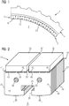
- einen Ausschnitt einer rotierenden elektrischen Maschine in einer schematischen Ansicht von vorn,
- FIG 2
- eine perspektivische Darstellung eines ersten Ausführungsbeispiels eines Rotorsegments,
- FIG 3
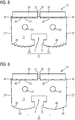
- schematisch ein zweites Ausführungsbeispiel eines Rotorsegments in einer Ansicht von vorn,
- FIG 4
- eine perspektivische Darstellung eines dritten Ausführungsbeispiels eines Rotorsegments,
- FIG 5
- schematisch das in
Figur 4 dargestellte dritte Ausführungsbeispiel eines Rotorsegments in einer Ansicht von vorn, und - FIG 6
- schematisch ein viertes Ausführungsbeispiel eines Rotorsegments in einer Ansicht von vorn.
- FIG. 1
- a section of a rotating electrical machine in a schematic view from the front,
- FIG. 2
- a perspective view of a first embodiment of a rotor segment,
- FIG. 3
- schematically a second embodiment of a rotor segment in a front view,
- FIG. 4
- a perspective view of a third embodiment of a rotor segment,
- FIG. 5
- schematically the in
FIG. 4 illustrated third embodiment of a rotor segment in a front view, and - FIG. 6
- schematically a fourth embodiment of a rotor segment in a front view.
Einander entsprechende Teile sind in allen Figuren mit den gleichen Bezugszeichen versehen.Corresponding parts are provided in all figures with the same reference numerals.
Der Segmentblechstapel 14 weist rotorachsenseitig eine axial, d. h. parallel zu der Rotorachse verlaufende Nut 21 zur Aufnahme eines Nutensteins 23 auf, mittels dessen das Rotorsegment 13 an dem Blechpaketträger 7 in bekannter Weise, beispielsweise mittels eines durch den Nutenstein 23 in den Blechpaketträger 7 geführten Schraubelements, befestigt wird. Jede Nut 21 hat ein T-förmiges Profil, wobei ein Nutgrund der Nut 21 den Balken des T bildet. Jeder Nutenstein 23 hat eine zu diesem Profil korrespondierende T-förmige Querschnittsfläche, so dass der Nutenstein 23 in die Nut 21 einschiebbar bzw. der Segmentblechstapel 14 auf den Nutenstein 23 aufschiebbar ist.The
Die Grundfläche 15 hat eine Grundflächenkontur, die aus einem rotorachsenseitigen ersten Konturabschnitt 25, einem dem ersten Konturabschnitt 25 gegenüber liegenden zweiten Konturabschnitt 26 und zwei dritten Konturabschnitten 27, die jeweils ein Ende des ersten Konturabschnitts 25 und ein Ende des zweiten Konturabschnitts 26 miteinander verbinden, besteht. Der erste Konturabschnitt 25 weist zwei ballige Auflageabschnitte 29 auf, zwischen denen ein Mittelabschnitt 31 liegt, der eine Querschnittsfläche der Nut 21 berandet, und die sich jeweils von dem Mittelabschnitt 31 bis zu einem der dritten Konturabschnitte 27 erstrecken.The
Der Segmentblechstapel 17 weist ferner zwei zur Rotorachse parallele Ausnehmungen 33 auf, die sich über die gesamte Länge des Segmentblechstapels 17 erstrecken und zur Aufnahme jeweils eines (nicht dargestellten) Verspannelements ausgebildet sind, das zum Verspannen der Segmentbleche 19 durch die Ausnehmung 33 geführt wird.The
Das Rotorsegment 13 umfasst ferner zwei quaderförmige Permanentmagneten 35, die an einer der Rotorachse gegenüber liegenden Seite der Stapelmantelfläche 17 des Segmentblechstapels 14 angeordnet sind und durch einen sich axial erstreckenden Zwischenraum 37 voneinander beabstandet sind. Dabei stehen sich entlang des Zwischenraums 37 ungleichnamige Magnetpole der Permanentmagneten 35 gegenüber. Zur Positionierung der Permanentmagneten 35 weist die der Rotorachse gegenüber liegende Seite der Stapelmantelfläche 17 einen mittig und axial verlaufenden Mittelsteg 39 und zwei jeweils entlang eines axialen Randes verlaufende Randstege 41 auf. Jeder Permanentmagnet 35 wird in einen Einlegbereich der Stapelmantelfläche 17 zwischen dem Mittelsteg 39 und einem der Randstege 41 eingelegt. In jedem dieser Einlegbereiche verlaufen drei axiale Wölbungen 43, auf denen einer der Permanentmagneten 35 aufliegt. Außerhalb der Wölbungen 43 entstehen dadurch zwischen einem Permanentmagnet 35 und dem jeweiligen Einlegbereich Klebespalte 45, in denen sich jeweils ein Klebstoff befindet, mittels dessen der Permanentmagnet 35 an die Stapelmantelfläche 17 geklebt ist.The
Die Rotorsegmente 13 sind jeweils an der Trägeroberfläche 9 des Blechpaketträgers 7 nebeneinander angeordnet, so dass die Grundflächen 15 der Segmentblechstapel 14 aller Rotorsegmente 13 senkrecht zur Rotorachse sind und jeweils mit ihren Auflageabschnitten 29 an dem Blechpaketträger 7 anliegen. Dabei sind je zwei benachbarte Rotorsegmente 13 derart orientiert, dass ihre nebeneinander liegenden Permanentmagneten 35 einander zugewandte ungleichnamige Magnetpole aufweisen.The
Bei der Herstellung des Rotorsegments 13 werden zunächst beispielsweise mittels eines Stanzwerkzeuges die Segmentbleche 19 hergestellt und zu dem Segmentblechstapel 14 verklebt. Anschließend werden die Permanentmagneten 35 auf den Segmentblechstapel 14 geklebt.In the manufacture of the
Bei der Herstellung des Rotorsegments 13 werden zunächst beispielsweise mittels eines Stanzwerkzeuges gestanzte Segmentbleche 19 zu den Segmentblechstapeln 14 zusammengefügt. Dann werden die Segmentblechstapel 14 mit jeweils zwei Permanentmagneten 35 bestückt. Die Segmentblechstapel 14 eines Rotorsegments 13 mit den Permanentmagneten 35 werden in eine Gießform eingelegt, deren Form und Größe zu der Anzahl der Segmentblechstapel 14 eines Rotorsegments 13 und deren relativer Lage korrespondiert, und in der Gießform mit Vergussmasse 47 vergossen.In the manufacture of the
Statt eines in
Die
Das in den
Analog zu
Obwohl die Erfindung im Detail durch bevorzugte Ausführungsbeispiele näher illustriert und beschrieben wurde, so ist die Erfindung nicht durch die offenbarten Beispiele eingeschränkt und andere Variationen können vom Fachmann hieraus abgeleitet werden, ohne den Schutzumfang der Erfindung zu verlassen.While the invention has been further illustrated and described in detail by way of preferred embodiments, the invention is not limited by the disclosed examples, and other variations can be derived therefrom by those skilled in the art without departing from the scope of the invention.
Claims (11)
- Rotor segment (13) of a rotor (3) of a rotating electrical machine (1), said rotor segment (13) comprising- at least one stack of segment laminations (14), which is designed as a cylinder having a basal surface (15) that is perpendicular to a rotor axis of the rotor (3) and a lateral surface (17) that is perpendicular to the basal surface (15), and which is composed of a multiplicity of segment laminations (19) that are identical in shape and are stacked in a direction that is parallel to the rotor axis,- wherein the basal surface (15) has a basal surface contour which consists of a first contour section (25) on the rotor-axis side, a second contour section (26) opposite to the first contour section (25), and two third contour sections (27), each of which connects an end of the first contour section (25) to an end of the second contour section (26),- and the first contour section (25) has at least one essentially dome-shaped support section (29),characterised in that- each stack of segment laminations (14) has a groove (21) on the rotor-axis side, said groove (21) running parallel to the rotor axis and being provided for the purpose of accommodating a groove block (23)- and each first contour section (25) has exactly two essentially dome-shaped support sections (29), between which is situated a centre section (31) that delimits a cross sectional area of the groove (21).
- Rotor segment (13) according to claim 1,
characterised in that each support section (29) extends from the centre section (31) to a third contour section (27). - Rotor segment (13) according to one of the preceding claims,
characterised in that at least one support section (29) has a plurality of concave subsections (49). - Rotor segment (13) according to claim 3,
characterised in that the subsections (49) of at least one support section (29) are designed such that of any two subsections (49), that subsection (49) which is closer to a third contour section (27) has a larger curvature. - Rotor segment (13) according to one of the preceding claims,
characterised in that at least one support section (29) has a plurality of straight subsections (49). - Rotor segment (13) according to one of the preceding claims,
characterised in that any two adjacent segment laminations (19) of at least one stack of segment laminations (14) are bonded together. - Rotor segment (13) according to one of the preceding claims,
characterised in that at least one stack of segment laminations (14) has an opening (33) which runs parallel to the rotor axis and extends over an entire length of the stack of segment laminations (14). - Rotor segment (13) according to one of the preceding claims,
characterised in that two permanent magnets (35) which are separated from each other by an intermediate space (37) that extends parallel to the rotor axis are arranged on that side of the lateral surface (17) of each stack of segment laminations (14) which is opposite to the rotor axis. - Rotor segment (13) according to one of the preceding claims,
characterised by at least two stacks of segment laminations (14) which are connected together by means of an encapsulating material (47) and are spatially fixed relative to each other, such that their basal surfaces (15) lie on a shared plane and their lateral surfaces (17) lie on the same side of this plane. - Rotor segment (13) according to claim 9,
characterised in that the encapsulating material (47) is a polyurethane. - Rotor (3) of a rotating electrical machine (1), said rotor (3) comprising- a laminated-core carrier (7) having a circular cylindrical carrier surface (9) whose cylinder axis coincides with a rotor axis of the rotor (3), and- a laminated core (11) which is composed of the stacks of segment laminations (14) of a plurality of rotor segments (13) according to one of the preceding claims,- wherein the rotor segments (13) are adjacently arranged on the carrier surface (9) of the laminated-core carrier (7), such that the basal surfaces (15) of the stacks of segment laminations (14) of all rotor segments (13) are perpendicular to the rotor axis and rest against the laminated-core carrier (7) with at least one support section (29) in each case.
Priority Applications (3)
| Application Number | Priority Date | Filing Date | Title |
|---|---|---|---|
| EP15152666.2A EP3051668B1 (en) | 2015-01-27 | 2015-01-27 | Rotor segment and rotor of an electric machine |
| CN201610051702.1A CN105827036B (en) | 2015-01-27 | 2016-01-26 | The rotor and rotor section of motor |
| US15/006,592 US10224773B2 (en) | 2015-01-27 | 2016-01-26 | Rotor segment and rotor of an electric machine |
Applications Claiming Priority (1)
| Application Number | Priority Date | Filing Date | Title |
|---|---|---|---|
| EP15152666.2A EP3051668B1 (en) | 2015-01-27 | 2015-01-27 | Rotor segment and rotor of an electric machine |
Publications (2)
| Publication Number | Publication Date |
|---|---|
| EP3051668A1 EP3051668A1 (en) | 2016-08-03 |
| EP3051668B1 true EP3051668B1 (en) | 2017-04-26 |
Family
ID=52432678
Family Applications (1)
| Application Number | Title | Priority Date | Filing Date |
|---|---|---|---|
| EP15152666.2A Not-in-force EP3051668B1 (en) | 2015-01-27 | 2015-01-27 | Rotor segment and rotor of an electric machine |
Country Status (3)
| Country | Link |
|---|---|
| US (1) | US10224773B2 (en) |
| EP (1) | EP3051668B1 (en) |
| CN (1) | CN105827036B (en) |
Families Citing this family (8)
| Publication number | Priority date | Publication date | Assignee | Title |
|---|---|---|---|---|
| WO2015157863A1 (en) * | 2014-04-15 | 2015-10-22 | Tm4 Inc. | Inserted permanent magnet rotor for an external rotor electric machine |
| US10340677B1 (en) * | 2016-12-14 | 2019-07-02 | NDI Engineering Company | Flexible electrical contact module |
| EP3402044B1 (en) * | 2017-05-10 | 2025-12-03 | GE Renewable Technologies Wind B.V. | Magnet module and method of manufacturing same |
| DE102019123434A1 (en) * | 2019-09-02 | 2021-03-04 | Schaeffler Technologies AG & Co. KG | Sheet metal ring for a laminated rotor core of a rotor of an electrical machine and method for producing a laminated rotor core from several sheet metal rings |
| CN110920376A (en) * | 2019-12-28 | 2020-03-27 | 江苏雅迪科技发展有限公司宁波分公司 | Salient-pole hub motor |
| EP4109717A1 (en) * | 2021-06-23 | 2022-12-28 | Siemens Gamesa Renewable Energy A/S | Rotor for an electric machine |
| DE102021124844A1 (en) * | 2021-09-27 | 2023-03-30 | Ebm-Papst Mulfingen Gmbh & Co. Kg | magnetic element holding device |
| US20250007380A1 (en) * | 2021-12-01 | 2025-01-02 | Mitsubishi Electric Corporation | Rotor and magnetic wave gear device |
Family Cites Families (15)
| Publication number | Priority date | Publication date | Assignee | Title |
|---|---|---|---|---|
| JPH0757076B2 (en) * | 1988-05-30 | 1995-06-14 | 三菱電機株式会社 | Rotating machine rotor |
| US5176946A (en) * | 1991-05-10 | 1993-01-05 | Allen-Bradley Company, Inc. | Laminated contactor core with blind hole |
| JP3282521B2 (en) * | 1996-07-08 | 2002-05-13 | トヨタ自動車株式会社 | Reluctance motor |
| JP4005169B2 (en) * | 1997-04-11 | 2007-11-07 | 東芝キヤリア株式会社 | Compressor |
| JP3688898B2 (en) * | 1998-08-21 | 2005-08-31 | 株式会社東芝 | Electric motor rotor |
| US6856051B2 (en) * | 2001-10-03 | 2005-02-15 | Delphi Technologies, Inc. | Manufacturing method and composite powder metal rotor assembly for circumferential type interior permanent magnet machine |
| US6603232B2 (en) * | 2001-11-02 | 2003-08-05 | Electric Boat Corporation | Permanent magnet retaining arrangement for high speed rotors |
| JP3998612B2 (en) * | 2003-08-19 | 2007-10-31 | ミネベア株式会社 | Impregnation and curing winding, impregnation and curing method therefor, impregnation and curing system, impregnation and curing apparatus, varnish coating apparatus |
| ITBZ20050062A1 (en) * | 2005-11-29 | 2007-05-30 | High Technology Invest Bv | PERMANENT MAGNET ROTOR FOR GENERATORS AND ELECTRIC MOTORS |
| JP5469307B2 (en) * | 2008-01-23 | 2014-04-16 | 株式会社三井ハイテック | Rotor laminated iron core |
| US8339005B2 (en) * | 2010-02-24 | 2012-12-25 | Indar Electric S.L. | Assembly and method for mounting magnets on a steel sheet rotor pack |
| DE102010023878A1 (en) * | 2010-06-15 | 2011-12-22 | Daimler Ag | Rotor i.e. inner rotor, for synchronous machine, has magnets with insulating layer that is designed such that maximum temperature of magnets is smaller than loading temperature of magnets during connection of core, carrier and magnets |
| US9935506B2 (en) * | 2012-08-31 | 2018-04-03 | Lappeenranta University Of Technology | Electrical machine |
| EP2712060B1 (en) * | 2012-09-25 | 2015-07-01 | ALSTOM Renewable Technologies | Permanent magnet modules and rotors |
| JP5737267B2 (en) | 2012-10-30 | 2015-06-17 | 株式会社デンソー | Rotor and rotating electric machine using the same |
-
2015
- 2015-01-27 EP EP15152666.2A patent/EP3051668B1/en not_active Not-in-force
-
2016
- 2016-01-26 CN CN201610051702.1A patent/CN105827036B/en not_active Expired - Fee Related
- 2016-01-26 US US15/006,592 patent/US10224773B2/en not_active Expired - Fee Related
Also Published As
| Publication number | Publication date |
|---|---|
| US10224773B2 (en) | 2019-03-05 |
| CN105827036B (en) | 2018-09-21 |
| CN105827036A (en) | 2016-08-03 |
| EP3051668A1 (en) | 2016-08-03 |
| US20160218574A1 (en) | 2016-07-28 |
Similar Documents
| Publication | Publication Date | Title |
|---|---|---|
| EP3051668B1 (en) | Rotor segment and rotor of an electric machine | |
| DE69310627T2 (en) | ROTOR OF A SYNCHRONOUS MOTOR | |
| DE102010010353B4 (en) | linear motor | |
| DE112014007129T5 (en) | A stator core for a rotary electric machine, a rotary electric machine, and a method of manufacturing a rotary electric machine | |
| DE112013002622T5 (en) | Rotor for a rotary electric machine, rotary electric machine, and method of manufacturing a rotor for a rotary electric machine | |
| WO1999010962A1 (en) | Electric machine with a rotor constructed of permanent magnets and magnetic flux guides | |
| DE102012100158A1 (en) | Stator for rotating electrical machines and method of making same | |
| DE10227859A1 (en) | Induction motor of the type with embedded permanent magnet, which allows the coil to be embedded easily | |
| DE102010040400A1 (en) | Rotor for an electric machine | |
| EP2157328B1 (en) | Bearing assembly for a machine table with magnetic load relieving | |
| EP2793365A1 (en) | Single segment rotor with single segments held by girders and method of manufacturing | |
| EP2790299A2 (en) | Stator core module | |
| DE102013110141A1 (en) | Rotating electrical machine | |
| WO2019171218A1 (en) | Rotor unit and electric motor | |
| DE102022116945A1 (en) | Rotor for an axial flux machine, and method for producing a rotor | |
| DE102020101149A1 (en) | Axial flux machine with mechanically fixed stator cores with radially extending sheet metal segments | |
| DE112004001898T5 (en) | Short circuit part, commutator and method for producing a short-circuit part | |
| DE112017003124T5 (en) | Rotor for rotating permanent magnet electric machine and rotating permanent magnet electric machine | |
| EP3729606A1 (en) | Rotor assembly or stator assembly having permanent magnets | |
| DE112016004389T5 (en) | ROTATING ELECTRICAL MACHINE AND MANUFACTURING METHOD FOR A ROTATING ELECTRIC MACHINE | |
| EP3076520B1 (en) | Rotor for an electric machine and production method | |
| WO2019171219A1 (en) | Rotor unit and electric motor | |
| DE102019107136A1 (en) | Claw pole stator for a transverse flux machine | |
| DE4443999C1 (en) | Permanent magnet transversal flux machine | |
| EP2871752B1 (en) | Rotor of a rotational permanently excited synchronous motor |
Legal Events
| Date | Code | Title | Description |
|---|---|---|---|
| PUAI | Public reference made under article 153(3) epc to a published international application that has entered the european phase |
Free format text: ORIGINAL CODE: 0009012 |
|
| 17P | Request for examination filed |
Effective date: 20151204 |
|
| AK | Designated contracting states |
Kind code of ref document: A1 Designated state(s): AL AT BE BG CH CY CZ DE DK EE ES FI FR GB GR HR HU IE IS IT LI LT LU LV MC MK MT NL NO PL PT RO RS SE SI SK SM TR |
|
| AX | Request for extension of the european patent |
Extension state: BA ME |
|
| GRAP | Despatch of communication of intention to grant a patent |
Free format text: ORIGINAL CODE: EPIDOSNIGR1 |
|
| RIC1 | Information provided on ipc code assigned before grant |
Ipc: H02K 1/27 20060101AFI20161026BHEP Ipc: H02K 1/28 20060101ALI20161026BHEP Ipc: H02K 15/12 20060101ALN20161026BHEP |
|
| INTG | Intention to grant announced |
Effective date: 20161121 |
|
| GRAS | Grant fee paid |
Free format text: ORIGINAL CODE: EPIDOSNIGR3 |
|
| GRAA | (expected) grant |
Free format text: ORIGINAL CODE: 0009210 |
|
| AK | Designated contracting states |
Kind code of ref document: B1 Designated state(s): AL AT BE BG CH CY CZ DE DK EE ES FI FR GB GR HR HU IE IS IT LI LT LU LV MC MK MT NL NO PL PT RO RS SE SI SK SM TR |
|
| REG | Reference to a national code |
Ref country code: GB Ref legal event code: FG4D Free format text: NOT ENGLISH |
|
| REG | Reference to a national code |
Ref country code: CH Ref legal event code: EP |
|
| REG | Reference to a national code |
Ref country code: AT Ref legal event code: REF Ref document number: 888647 Country of ref document: AT Kind code of ref document: T Effective date: 20170515 |
|
| REG | Reference to a national code |
Ref country code: IE Ref legal event code: FG4D Free format text: LANGUAGE OF EP DOCUMENT: GERMAN |
|
| REG | Reference to a national code |
Ref country code: CH Ref legal event code: NV Representative=s name: SIEMENS SCHWEIZ AG, CH |
|
| REG | Reference to a national code |
Ref country code: DE Ref legal event code: R096 Ref document number: 502015000909 Country of ref document: DE |
|
| RAP2 | Party data changed (patent owner data changed or rights of a patent transferred) |
Owner name: SIEMENS AKTIENGESELLSCHAFT |
|
| REG | Reference to a national code |
Ref country code: NL Ref legal event code: MP Effective date: 20170426 |
|
| REG | Reference to a national code |
Ref country code: LT Ref legal event code: MG4D |
|
| PG25 | Lapsed in a contracting state [announced via postgrant information from national office to epo] |
Ref country code: NL Free format text: LAPSE BECAUSE OF FAILURE TO SUBMIT A TRANSLATION OF THE DESCRIPTION OR TO PAY THE FEE WITHIN THE PRESCRIBED TIME-LIMIT Effective date: 20170426 |
|
| REG | Reference to a national code |
Ref country code: CH Ref legal event code: PCOW Free format text: NEW ADDRESS: WERNER-VON-SIEMENS-STRASSE 1, 80333 MUENCHEN (DE) |
|
| PG25 | Lapsed in a contracting state [announced via postgrant information from national office to epo] |
Ref country code: GR Free format text: LAPSE BECAUSE OF FAILURE TO SUBMIT A TRANSLATION OF THE DESCRIPTION OR TO PAY THE FEE WITHIN THE PRESCRIBED TIME-LIMIT Effective date: 20170727 Ref country code: ES Free format text: LAPSE BECAUSE OF FAILURE TO SUBMIT A TRANSLATION OF THE DESCRIPTION OR TO PAY THE FEE WITHIN THE PRESCRIBED TIME-LIMIT Effective date: 20170426 Ref country code: LT Free format text: LAPSE BECAUSE OF FAILURE TO SUBMIT A TRANSLATION OF THE DESCRIPTION OR TO PAY THE FEE WITHIN THE PRESCRIBED TIME-LIMIT Effective date: 20170426 Ref country code: NO Free format text: LAPSE BECAUSE OF FAILURE TO SUBMIT A TRANSLATION OF THE DESCRIPTION OR TO PAY THE FEE WITHIN THE PRESCRIBED TIME-LIMIT Effective date: 20170726 Ref country code: HR Free format text: LAPSE BECAUSE OF FAILURE TO SUBMIT A TRANSLATION OF THE DESCRIPTION OR TO PAY THE FEE WITHIN THE PRESCRIBED TIME-LIMIT Effective date: 20170426 Ref country code: FI Free format text: LAPSE BECAUSE OF FAILURE TO SUBMIT A TRANSLATION OF THE DESCRIPTION OR TO PAY THE FEE WITHIN THE PRESCRIBED TIME-LIMIT Effective date: 20170426 |
|
| PG25 | Lapsed in a contracting state [announced via postgrant information from national office to epo] |
Ref country code: RS Free format text: LAPSE BECAUSE OF FAILURE TO SUBMIT A TRANSLATION OF THE DESCRIPTION OR TO PAY THE FEE WITHIN THE PRESCRIBED TIME-LIMIT Effective date: 20170426 Ref country code: LV Free format text: LAPSE BECAUSE OF FAILURE TO SUBMIT A TRANSLATION OF THE DESCRIPTION OR TO PAY THE FEE WITHIN THE PRESCRIBED TIME-LIMIT Effective date: 20170426 Ref country code: IS Free format text: LAPSE BECAUSE OF FAILURE TO SUBMIT A TRANSLATION OF THE DESCRIPTION OR TO PAY THE FEE WITHIN THE PRESCRIBED TIME-LIMIT Effective date: 20170826 Ref country code: SE Free format text: LAPSE BECAUSE OF FAILURE TO SUBMIT A TRANSLATION OF THE DESCRIPTION OR TO PAY THE FEE WITHIN THE PRESCRIBED TIME-LIMIT Effective date: 20170426 Ref country code: PL Free format text: LAPSE BECAUSE OF FAILURE TO SUBMIT A TRANSLATION OF THE DESCRIPTION OR TO PAY THE FEE WITHIN THE PRESCRIBED TIME-LIMIT Effective date: 20170426 Ref country code: BG Free format text: LAPSE BECAUSE OF FAILURE TO SUBMIT A TRANSLATION OF THE DESCRIPTION OR TO PAY THE FEE WITHIN THE PRESCRIBED TIME-LIMIT Effective date: 20170726 |
|
| REG | Reference to a national code |
Ref country code: FR Ref legal event code: PLFP Year of fee payment: 4 |
|
| REG | Reference to a national code |
Ref country code: DE Ref legal event code: R097 Ref document number: 502015000909 Country of ref document: DE |
|
| PG25 | Lapsed in a contracting state [announced via postgrant information from national office to epo] |
Ref country code: CZ Free format text: LAPSE BECAUSE OF FAILURE TO SUBMIT A TRANSLATION OF THE DESCRIPTION OR TO PAY THE FEE WITHIN THE PRESCRIBED TIME-LIMIT Effective date: 20170426 Ref country code: SK Free format text: LAPSE BECAUSE OF FAILURE TO SUBMIT A TRANSLATION OF THE DESCRIPTION OR TO PAY THE FEE WITHIN THE PRESCRIBED TIME-LIMIT Effective date: 20170426 Ref country code: DK Free format text: LAPSE BECAUSE OF FAILURE TO SUBMIT A TRANSLATION OF THE DESCRIPTION OR TO PAY THE FEE WITHIN THE PRESCRIBED TIME-LIMIT Effective date: 20170426 Ref country code: EE Free format text: LAPSE BECAUSE OF FAILURE TO SUBMIT A TRANSLATION OF THE DESCRIPTION OR TO PAY THE FEE WITHIN THE PRESCRIBED TIME-LIMIT Effective date: 20170426 Ref country code: RO Free format text: LAPSE BECAUSE OF FAILURE TO SUBMIT A TRANSLATION OF THE DESCRIPTION OR TO PAY THE FEE WITHIN THE PRESCRIBED TIME-LIMIT Effective date: 20170426 |
|
| PG25 | Lapsed in a contracting state [announced via postgrant information from national office to epo] |
Ref country code: SM Free format text: LAPSE BECAUSE OF FAILURE TO SUBMIT A TRANSLATION OF THE DESCRIPTION OR TO PAY THE FEE WITHIN THE PRESCRIBED TIME-LIMIT Effective date: 20170426 |
|
| PLBE | No opposition filed within time limit |
Free format text: ORIGINAL CODE: 0009261 |
|
| STAA | Information on the status of an ep patent application or granted ep patent |
Free format text: STATUS: NO OPPOSITION FILED WITHIN TIME LIMIT |
|
| 26N | No opposition filed |
Effective date: 20180129 |
|
| PG25 | Lapsed in a contracting state [announced via postgrant information from national office to epo] |
Ref country code: MT Free format text: LAPSE BECAUSE OF FAILURE TO SUBMIT A TRANSLATION OF THE DESCRIPTION OR TO PAY THE FEE WITHIN THE PRESCRIBED TIME-LIMIT Effective date: 20170426 |
|
| PG25 | Lapsed in a contracting state [announced via postgrant information from national office to epo] |
Ref country code: LU Free format text: LAPSE BECAUSE OF NON-PAYMENT OF DUE FEES Effective date: 20180127 |
|
| REG | Reference to a national code |
Ref country code: IE Ref legal event code: MM4A |
|
| REG | Reference to a national code |
Ref country code: BE Ref legal event code: MM Effective date: 20180131 |
|
| PG25 | Lapsed in a contracting state [announced via postgrant information from national office to epo] |
Ref country code: BE Free format text: LAPSE BECAUSE OF NON-PAYMENT OF DUE FEES Effective date: 20180131 |
|
| REG | Reference to a national code |
Ref country code: FR Ref legal event code: PLFP Year of fee payment: 5 |
|
| PG25 | Lapsed in a contracting state [announced via postgrant information from national office to epo] |
Ref country code: IE Free format text: LAPSE BECAUSE OF NON-PAYMENT OF DUE FEES Effective date: 20180127 |
|
| PGFP | Annual fee paid to national office [announced via postgrant information from national office to epo] |
Ref country code: FR Payment date: 20190124 Year of fee payment: 5 Ref country code: DE Payment date: 20190319 Year of fee payment: 5 Ref country code: IT Payment date: 20190130 Year of fee payment: 5 |
|
| PG25 | Lapsed in a contracting state [announced via postgrant information from national office to epo] |
Ref country code: MC Free format text: LAPSE BECAUSE OF FAILURE TO SUBMIT A TRANSLATION OF THE DESCRIPTION OR TO PAY THE FEE WITHIN THE PRESCRIBED TIME-LIMIT Effective date: 20170426 |
|
| GBPC | Gb: european patent ceased through non-payment of renewal fee |
Effective date: 20190127 |
|
| PGFP | Annual fee paid to national office [announced via postgrant information from national office to epo] |
Ref country code: CH Payment date: 20190402 Year of fee payment: 5 |
|
| PG25 | Lapsed in a contracting state [announced via postgrant information from national office to epo] |
Ref country code: GB Free format text: LAPSE BECAUSE OF NON-PAYMENT OF DUE FEES Effective date: 20190127 |
|
| PG25 | Lapsed in a contracting state [announced via postgrant information from national office to epo] |
Ref country code: TR Free format text: LAPSE BECAUSE OF FAILURE TO SUBMIT A TRANSLATION OF THE DESCRIPTION OR TO PAY THE FEE WITHIN THE PRESCRIBED TIME-LIMIT Effective date: 20170426 |
|
| PG25 | Lapsed in a contracting state [announced via postgrant information from national office to epo] |
Ref country code: PT Free format text: LAPSE BECAUSE OF FAILURE TO SUBMIT A TRANSLATION OF THE DESCRIPTION OR TO PAY THE FEE WITHIN THE PRESCRIBED TIME-LIMIT Effective date: 20170426 |
|
| PG25 | Lapsed in a contracting state [announced via postgrant information from national office to epo] |
Ref country code: MK Free format text: LAPSE BECAUSE OF NON-PAYMENT OF DUE FEES Effective date: 20170426 Ref country code: HU Free format text: LAPSE BECAUSE OF FAILURE TO SUBMIT A TRANSLATION OF THE DESCRIPTION OR TO PAY THE FEE WITHIN THE PRESCRIBED TIME-LIMIT; INVALID AB INITIO Effective date: 20150127 Ref country code: CY Free format text: LAPSE BECAUSE OF FAILURE TO SUBMIT A TRANSLATION OF THE DESCRIPTION OR TO PAY THE FEE WITHIN THE PRESCRIBED TIME-LIMIT Effective date: 20170426 |
|
| PG25 | Lapsed in a contracting state [announced via postgrant information from national office to epo] |
Ref country code: AL Free format text: LAPSE BECAUSE OF FAILURE TO SUBMIT A TRANSLATION OF THE DESCRIPTION OR TO PAY THE FEE WITHIN THE PRESCRIBED TIME-LIMIT Effective date: 20170426 |
|
| REG | Reference to a national code |
Ref country code: DE Ref legal event code: R119 Ref document number: 502015000909 Country of ref document: DE |
|
| REG | Reference to a national code |
Ref country code: CH Ref legal event code: PL |
|
| PG25 | Lapsed in a contracting state [announced via postgrant information from national office to epo] |
Ref country code: DE Free format text: LAPSE BECAUSE OF NON-PAYMENT OF DUE FEES Effective date: 20200801 Ref country code: FR Free format text: LAPSE BECAUSE OF NON-PAYMENT OF DUE FEES Effective date: 20200131 |
|
| PG25 | Lapsed in a contracting state [announced via postgrant information from national office to epo] |
Ref country code: SI Free format text: LAPSE BECAUSE OF NON-PAYMENT OF DUE FEES Effective date: 20180127 Ref country code: CH Free format text: LAPSE BECAUSE OF NON-PAYMENT OF DUE FEES Effective date: 20200131 Ref country code: LI Free format text: LAPSE BECAUSE OF NON-PAYMENT OF DUE FEES Effective date: 20200131 |
|
| PG25 | Lapsed in a contracting state [announced via postgrant information from national office to epo] |
Ref country code: IT Free format text: LAPSE BECAUSE OF NON-PAYMENT OF DUE FEES Effective date: 20200127 |
|
| REG | Reference to a national code |
Ref country code: AT Ref legal event code: MM01 Ref document number: 888647 Country of ref document: AT Kind code of ref document: T Effective date: 20200127 |
|
| PG25 | Lapsed in a contracting state [announced via postgrant information from national office to epo] |
Ref country code: AT Free format text: LAPSE BECAUSE OF NON-PAYMENT OF DUE FEES Effective date: 20200127 |