EP4443707A1 - Rotating electric machine rotor - Google Patents
Rotating electric machine rotor Download PDFInfo
- Publication number
- EP4443707A1 EP4443707A1 EP23780455.4A EP23780455A EP4443707A1 EP 4443707 A1 EP4443707 A1 EP 4443707A1 EP 23780455 A EP23780455 A EP 23780455A EP 4443707 A1 EP4443707 A1 EP 4443707A1
- Authority
- EP
- European Patent Office
- Prior art keywords
- magnet
- circumferential direction
- permanent magnet
- bridge portion
- axis
- Prior art date
- Legal status (The legal status is an assumption and is not a legal conclusion. Google has not performed a legal analysis and makes no representation as to the accuracy of the status listed.)
- Withdrawn
Links
Images



Classifications
-
- H—ELECTRICITY
- H02—GENERATION; CONVERSION OR DISTRIBUTION OF ELECTRIC POWER
- H02K—DYNAMO-ELECTRIC MACHINES
- H02K1/00—Details of the magnetic circuit
- H02K1/06—Details of the magnetic circuit characterised by the shape, form or construction
- H02K1/22—Rotating parts of the magnetic circuit
- H02K1/27—Rotor cores with permanent magnets
- H02K1/2706—Inner rotors
- H02K1/272—Inner rotors the magnetisation axis of the magnets being perpendicular to the rotor axis
- H02K1/274—Inner rotors the magnetisation axis of the magnets being perpendicular to the rotor axis the rotor consisting of two or more circumferentially positioned magnets
- H02K1/2753—Inner rotors the magnetisation axis of the magnets being perpendicular to the rotor axis the rotor consisting of two or more circumferentially positioned magnets the rotor consisting of magnets or groups of magnets arranged with alternating polarity
- H02K1/276—Magnets embedded in the magnetic core, e.g. interior permanent magnets [IPM]
- H02K1/2766—Magnets embedded in the magnetic core, e.g. interior permanent magnets [IPM] having a flux concentration effect
-
- H—ELECTRICITY
- H02—GENERATION; CONVERSION OR DISTRIBUTION OF ELECTRIC POWER
- H02K—DYNAMO-ELECTRIC MACHINES
- H02K2213/00—Specific aspects, not otherwise provided for and not covered by codes H02K2201/00 - H02K2211/00
- H02K2213/03—Machines characterised by numerical values, ranges, mathematical expressions or similar information
-
- Y—GENERAL TAGGING OF NEW TECHNOLOGICAL DEVELOPMENTS; GENERAL TAGGING OF CROSS-SECTIONAL TECHNOLOGIES SPANNING OVER SEVERAL SECTIONS OF THE IPC; TECHNICAL SUBJECTS COVERED BY FORMER USPC CROSS-REFERENCE ART COLLECTIONS [XRACs] AND DIGESTS
- Y02—TECHNOLOGIES OR APPLICATIONS FOR MITIGATION OR ADAPTATION AGAINST CLIMATE CHANGE
- Y02T—CLIMATE CHANGE MITIGATION TECHNOLOGIES RELATED TO TRANSPORTATION
- Y02T10/00—Road transport of goods or passengers
- Y02T10/60—Other road transportation technologies with climate change mitigation effect
- Y02T10/64—Electric machine technologies in electromobility
Definitions
- the present disclosure relates to rotors for rotating electrical machines.
- a technique is known in which a plurality of permanent magnets is arranged in a two-layer structure in a rotor core.
- Patent Document 1 Japanese Unexamined Patent Application Publication No. 2019-54659 ( JP 2019-54659 A )
- a rotor for a rotating electrical machine includes: a rotor core having a radially outer first magnet hole and a radially inner second magnet hole;
- the rotor core includes a first portion located radially outward of the first magnet hole, a second portion extending between the first magnet hole and the second magnet hole in such a manner that both sides in a circumferential direction of the second portion extend to an outer peripheral surface of the rotor core, a third portion extending radially inward of the second magnet hole in such a manner that both sides in the circumferential direction of the third portion extend to the outer peripheral surface of the rotor core, and a plurality of bridge portions located radially inward of the outer peripheral surface of the rotor core and connecting the third portion and the second portion.
- the second permanent magnet includes a d-axis-side second permanent magnet located on a d-axis or near the d-axis.
- a separation distance of the d-axis-side second permanent magnet from the first permanent magnet is smaller at a position closer to at least one of the plurality of bridge portions in the circumferential direction than at a position farther from the at least one bridge portion in the circumferential direction along a side of the d-axis-side second permanent magnet that faces the first permanent magnet, as viewed in an axial direction.
- the at least one bridge portion extends radially inward beyond a radially inner edge of a circumferential end of the d-axis-side second permanent magnet facing the at least one bridge portion in the circumferential direction.
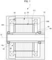
- FIG. 1 is a sectional view schematically showing a sectional structure of a motor 1 according to an embodiment.
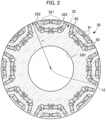
- FIG. 2 is a sectional view of a rotor 30 (sectional view taken along a plane perpendicular to an axial direction).
- reference signs may be given only to part of a plurality of portions having the same attribute.
- FIG. 1 shows a rotation axis 12 of the motor 1.
- the axial direction refers to a direction in which the rotation axis (rotation center) 12 of the motor 1 extends
- the radial direction refers to a radial direction about the rotation axis 12. Therefore, “radially outer” and “radially outward” refer to a side away from the rotation axis 12, and the “radially inner” and “radially inward” refers to a side toward the rotation axis 12.
- the circumferential direction corresponds to a rotation direction about the rotation axis 12.
- the motor 1 may be a vehicle drive motor that is used in, for example, a hybrid electric vehicle or a battery electric vehicle. However, the motor 1 may be used for any other purposes.
- the motor 1 is of an inner rotor type, and a stator 21 is provided so as to surround the radially outer side of the rotor 30.
- the radially outer side of the stator 21 is fixed to a motor housing 10.
- the stator 21 includes a stator core 211 composed of, for example, annular magnetic steel laminations, and a plurality of slots (not shown) around which a coil 22 is wound is provided on the radially inner side of the stator core 211.
- the rotor 30 is disposed radially inward of the stator 21.
- the rotor 30 includes a rotor core 32, a rotor shaft 34, end plates 35A, 35B, and permanent magnets 61, 62.
- the rotor core 32 is fixed to the radially outer surface of the rotor shaft 34 and rotates with the rotor shaft 34.
- the rotor core 32 has a shaft hole 320 (see FIG. 2 ), and the rotor shaft 34 is fitted in the shaft hole 320.
- the rotor core 32 may be fixed to the rotor shaft 34 by shrink fitting, press fitting, or the like.
- the rotor core 32 may be coupled to the rotor shaft 34 by key coupling or spline coupling.
- the rotor shaft 34 is rotatably supported by the motor housing 10 via bearings 14a, 14b.
- the rotor shaft 34 defines the rotation axis 12 of the motor 1.
- the rotor core 32 is composed of, for example, annular magnetic steel laminations.
- the permanent magnets 61, 62 (see FIG. 2 ) are embedded in the rotor core 32. That is, the rotor core 32 has magnet holes 321, 322 (see FIG. 2 ) extending through the rotor core 32 in the axial direction, and the permanent magnets 61, 62 are inserted and fixed in the magnet holes 321, 322.
- the rotor core 32 may be made of a green compact obtained by pressing and compacting magnetic powder.
- the rotor core 32 is designed in a circular shape having a first radius r1, and the outer peripheral surface of the rotor core 32 includes portions having the first radius r1 (outer peripheral surface portions 328B, parts 328C, etc., which will be described later).
- an outer peripheral surface 328 of the rotor core 32 has the first radius r1.
- the circular shape of the rotor core 32 does not have to be a perfect circle, and may be, for example, a circular shape having a cut in its part.
- the rotor core 32 has a rotationally symmetric form about the rotation axis 12 as viewed in the axial direction.
- the rotor core 32 has a form in which the permanent magnets 61, 62 of individual sets overlap every time the rotor core 32 rotates by 45 degrees about the rotation axis 12.
- the plurality of permanent magnets 61, 62 may be made of neodymium etc.
- the plurality of permanent magnets 61, 62 is arranged in pairs of the permanent magnets 61 and pairs of the permanent magnets 62 as viewed in the axial direction.
- a common magnetic pole is formed between a pair of permanent magnets 61 and between a pair of permanent magnets 62.
- the plurality of permanent magnets 61, 62 is arranged in such a manner that S poles and N poles appear alternately in the circumferential direction.
- the number of magnetic poles is eight, but the number of magnetic poles may be set as desired.
- the permanent magnets 61, 62 are in the same linear form as viewed in the axial direction.
- the permanent magnets 61, 62 may be in different forms. Either or both of the permanent magnets 61, 62 may be in a circular arc-shaped form as viewed in the axial direction.
- FIG. 1 shows the motor 1 having a specific structure
- the structure of the motor 1 is not limited to such a specific structure.
- the rotor shaft 34 is hollow.
- the rotor shaft 34 may be solid.
- FIG. 3 is an enlarged view of a portion related to one magnetic pole shown in FIG. 2 .
- the configuration related to one magnetic pole is basically symmetrical with respect to a d-axis (shown by "d-axis" in English in FIG. 3 ).
- d-axis shown by "d-axis” in English in FIG. 3 .
- circumferentially outer and “circumferentially outward” refer to a side away from the d-axis
- the “circumferentially inner” and “circumferentially inward” refers to a side toward the d-axis.
- the rotor core 32 has the radially outer magnet holes 321 (hereinafter referred to as “first magnet holes 321”) and the radially inner magnet holes 322 (hereinafter referred to as “second magnet holes 322").
- the first magnet holes 321 are provided in a pair such that the two first magnet holes 321 of the pair form a substantially V-shape (substantially V-shape that opens radially outward or radially inward).
- the first magnet holes 321 may be provided in a pair such that the two first magnet holes 321 of the pair form a straight line shape, or the straight line shape may be implemented by a single straight hole (having a straight line shape perpendicular to the d-axis).
- a permanent magnet 61 is provided in each first magnet hole 321.
- a clearance may be provided between the first magnet hole 321 and the permanent magnet 61 at both longitudinal ends of the permanent magnet 61. The clearance may be an empty space or may be filled with resin etc.
- the second magnet holes 322 are provided radially inward of the first magnet holes 321. Like the first magnet holes 321, the second magnet holes 322 are provided in a pair symmetrical with respect to the d axis. The second magnet holes 322 on both sides of the d axis in the circumferential direction extend in a wider range in the circumferential direction than the first magnet holes 321 on both sides of the d axis in the circumferential direction.
- a permanent magnet 62 is provided in each second magnet hole 322.
- a clearance may be provided between the second magnet hole 322 and the permanent magnet 62 at both longitudinal ends of the permanent magnet 62. The clearance may be an empty space or may be filled with resin etc.
- two second magnet holes 322 are provided on one side in the circumferential direction of the d-axis, and two second magnet holes 322 are provided on the other side in the circumferential direction of the d-axis. That is, a total of four second magnet holes 322 are provided for one magnetic pole.
- the rotor core 32 Since the rotor core 32 has such first magnet holes 321 and second magnet holes 322, the rotor core 32 has three portions 3211, 3212, and 3213 connected in the radial direction only via bridge portions (hereinafter also referred to as "first portion 3211,” “second portion 3212,” and “third portion 3213").
- the first portion 3211 extends radially outward of the first magnet holes 321.
- the first portion 3211 forms a part 328A (see FIG. 3 ) of the outer peripheral surface 328 of the rotor core 32.
- the second portion 3212 extends between the second magnet holes 322 and the first magnet holes 321 such that both sides in the circumferential direction of the second portion 3212 extend to the outer peripheral surface 328 of the rotor core 32.
- the second portion 3212 forms parts 328B of the outer peripheral surface 328 of the rotor core 32 (hereinafter also referred to as "outer peripheral surface portions 328B of the second portion 3212") (see FIG. 3 ) on both sides in the circumferential direction of the first portion 3211.
- the second portion 3212 forms a magnetic path for q-axis magnetic flux.
- the q-axis magnetic flux flows between the second magnet holes 322 and the first magnet holes 321 from one end (outer peripheral surface portion 328B on one side) toward the other end (outer peripheral surface portion 328B on the other side) of the second portion 3212.
- the third portion 3213 extends radially inward of the second magnet holes 322 such that both sides in the circumferential direction of the third portion 3213 extend to the outer peripheral surface 328 of the rotor core 32.
- the third portion 3213 forms parts 328C (see FIG. 3 ) of the outer peripheral surface 328 of the rotor core 32 on both sides in the circumferential direction of the second portion 3212.
- the mass of the third portion 3213 is significantly larger than the mass of the second portion 3212, and the mass of the second portion 3212 is significantly larger than the mass of the first portion 3211.
- the rotor core 32 Since the rotor core 32 has such three portions 3211, 3212, and 3213, the rotor core 32 has a plurality of bridge portions 41, 42, 43, 44, and 45 connecting the three portions 3211, 3212, and 3213.
- the bridge portions 41 (hereinafter referred to as “first bridge portions 41") support the first portion 3211 radially outward of the second portion 3212. That is, the first bridge portions 41 connect the second portion 3212 and the first portion 3211 and extend in the circumferential direction.
- the first bridge portions 41 are provided in a pair on both sides in the circumferential direction of (circumferentially outward of) the first portion 3211.
- the bridge portions 42 (hereinafter referred to as “second bridge portions 42") support the second portion 3212 radially outward of the third portion 3213. That is, the second bridge portions 42 connect the third portion 3213 and the second portion 3212 and extend in the circumferential direction.
- the second bridge portions 42 are provided in a pair on both sides in the circumferential direction of (circumferentially outward of) the second portion 3212.
- the bridge portion 43 (hereinafter referred to as "first center bridge portion 43") supports the first portion 3211 on the d-axis with respect to the second portion 3212.
- the bridge portion 44 (hereinafter referred to as "second center bridge portion 44") supports the second portion 3212 on the d-axis with respect to the third portion 3213.
- the bridge portions 45 (hereinafter referred to as the "second intermediate bridge portions 45") each support the second portion 3212 between two second magnet holes 322 with respect to the third portion 3213.
- FIG. 4 is a further enlarged view of the portion of FIG. 3 , showing lines for describing shape features.
- FIG. 5 is a diagram illustrating part of effects of the present embodiment in comparison with a comparative example.
- the comparative example is shown on the right side
- the present embodiment is shown on the left side
- the flow of the q-axis magnetic flux in the comparative example and the present embodiment is schematically shown by arrows R5, R5', respectively.
- the second magnet holes 322 and the permanent magnets 62 refer to the circumferentially inner second magnet holes 322 and permanent magnets 62 out of the circumferentially outer and circumferentially inner second magnet holes 322 and permanent magnets 62, unless otherwise specified.
- the permanent magnets 62 each have a smaller separation distance d from the permanent magnet 61 at a circumferential position closer to the second center bridge portion 44 than at a circumferential position farther from the second center bridge portion 44 in the circumferential direction along a side 624 of the permanent magnet 62 that faces the permanent magnet 61, as viewed in the axial direction. That is, the permanent magnets 62 each have a smaller separation distance d from the permanent magnet 61 at a circumferentially inner position than at a circumferentially outer position.
- FIG. 4 the permanent magnets 62 each have a smaller separation distance d from the permanent magnet 61 at a circumferential position closer to the second center bridge portion 44 than at a circumferential position farther from the second center bridge portion 44 in the circumferential direction along a side 624 of the permanent magnet 62 that faces the permanent magnet 61, as viewed in the axial direction. That is, the permanent magnets 62 each have a smaller separation distance d from the permanent magnet 61 at a circumferentially
- the separation distances d of the permanent magnet 62 from the permanent magnet 61 at the circumferentially inner position on the permanent magnet 62 and at the circumferentially outer position on the permanent magnet 62 are denoted by d(1) and d(2), respectively, for a distinguishing purpose.
- the separation distance d may be a distance perpendicular to the side 624 of the permanent magnet 62 that faces the permanent magnet 61, as viewed in the axial direction.
- the separation distance d between the permanent magnet 62 and the permanent magnet 61 is a separation distance in a plane perpendicular to the axial direction (i.e., a separation distance in a plane including the plane of paper of FIG.
- the permanent magnets 62 in the two adjacent second magnet holes 322 with the second center bridge portion 44 interposed therebetween in the circumferential direction may be each disposed in such an orientation that the side of the permanent magnet 62 that is closer to the d-axis in the circumferential direction is located radially outward of the side of the permanent magnet 62 that is farther from the d-axis in the circumferential direction. That is, the permanent magnets 62 in the two adjacent second magnet holes 322 with the second center bridge portion 44 interposed therebetween in the circumferential direction may be arranged in a V-shape pointing radially outward.
- the amount of the second portion 3212 can be relatively reduced without significantly reducing the width of the second portion 3212 (magnetic path width).
- stress radially outward tensile stress
- the second center bridge portion 44 extends radially inward beyond radially inner edges 6211 of circumferential ends 621 of the permanent magnets 62 facing the second center bridge portion 44 in the circumferential direction.
- the second center bridge portion 44 extends radially inward beyond the line segment L2.
- the second center bridge portion 44 does not extend radially outward beyond radially outer edges 6212 of the circumferential ends 621 of the permanent magnets 62 facing the second center bridge portion 44 in the circumferential direction.
- the radial length of the second center bridge portion 44 is significantly larger than the radial width d0 of the permanent magnets 62, and extends radially inward beyond the circumferential ends 621 of the permanent magnets 62.
- rounded corners R1, R2 on both radial sides of the second center bridge portion 44 can be made relatively large. This can effectively reduce stress concentration (stress concentration due to the centrifugal force) on both radial ends of the second center bridge portion 44.
- the second center bridge portion 44 is extended radially inward beyond the line segment L2 in order to increase the radial length of the second center bridge portion 44.
- This can reduce a disadvantage that tends to occur in the comparative example (see rotor core 32' in FIG. 5 ) in which a second center bridge portion 44' is extended radially outward beyond the above line segment L1 (see FIG. 4 ) in order to increase the radial length of the second center bridge portion 44'.
- the width of a second portion 3212' is reduced accordingly.
- the radially outward extension of the second center bridge portion 44' is accompanied by radially outward extension of second magnet holes 322' located circumferentially outward of the second center bridge portion 44'.
- the reduction in width of the second portion 3212' causes a decrease in reluctance torque.
- the radial length of the second center bridge portion 44 is increased without causing the second center bridge portion 44 to extend radially outward beyond the line segment L1, as described above. Therefore, the width of the second portion 3212 (magnetic path width) is not reduced due to the second center bridge portion 44.
- the radial length of the second center bridge portion 44 is increased, it is possible to reduce stress concentration on the second center bridge portion 44 (and as a result, increase the rotational speed of the motor 1) and to effectively prevent a decrease in reluctance torque (decrease in width of the second portion 3212) due to the increase in radial length of the second center bridge portion 44.
- the second magnet holes 322 each have a first overhang portion 3221 at its end closer to the second center bridge portion 44 in the circumferential direction (hereinafter also simply referred to as "circumferentially inner end 322-1").
- the first overhang portion 3221 extends toward (overhangs) the permanent magnet 62 in the circumferential direction on the radially inner side of the circumferentially inner end 322-1.
- the first overhang portion 3221 may overlap the permanent magnet 62 with a part 3201 of the rotor core 32 therebetween as viewed in the radial direction.
- the first overhang portion 3221 is formed so as to be continuous from the rounded corner R2, forms a rounded corner R3, and then terminates with a rounded corner R4 near the vertex on the radially inner side and circumferentially inner side of the permanent magnet 62.
- Such a first overhang portion 3221 has a function to reduce an increase in back electromotive voltage.
- the second magnet holes 322 each have a second overhang portion 3222 at its end farther from the second center bridge portion 44 in the circumferential direction (hereinafter also simply referred to as "circumferentially outer end 322-2").
- the second overhang portion 3222 extends toward (overhangs) the permanent magnet 62 in the circumferential direction on the radially outer side of the circumferentially outer end 322-2.
- the second overhang portion 3222 may overlap the permanent magnet 62 with a part 3202 of the rotor core 32 therebetween as viewed in the radial direction.
- the second overhang portion 3222 may be provided in the common second magnet hole 322 in a diagonal positional relationship with the first overhang portion 3221. In this case, the function of the second overhang portion 3222 (function to reduce an increase in back electromotive force) is added, so that an increase in back electromotive force can be effectively reduced.
- the second overhang portion 3222 enlarges the second magnet hole 322 toward the second portion 3212 (i.e., causes the second intermediate bridge portion 45 to extend radially outward beyond the permanent magnet 62), the width of the second portion 3212 (magnetic path width) may be reduced depending on the shape of the second overhang portion 3222 etc. Therefore, the second overhang portion 3222 is preferably formed so as not to significantly reduce the width of the second portion 3212 (magnetic path width). Particularly in the present embodiment, as described above, the separation distance d between the permanent magnet 62 and the permanent magnet 61 is greater at a circumferentially outer position on the permanent magnet 62 than at a circumferentially inner position on the permanent magnet 62.
- the second overhang portion 3222 at a circumferentially outer position on the permanent magnet 62 rather than at a circumferentially inner position on the permanent magnet 62 makes it easier to allow the second portion 3212 to have a necessary width (magnetic path width).
- the circumferentially outer second magnet holes 322 each also have an overhang portion 3223 in such a manner that the overhang portion 3223 faces the second overhang portion 3222 in the circumferential direction.
- the function of the overhang portion 3223 (function to reduce an increase in back electromotive force) is added, so that an increase in back electromotive force can be effectively reduced.
- FIG. 6 is an enlarged view of a portion related to one magnetic pole according to another embodiment.
- second magnet holes 322A and permanent magnets 62 refer to the circumferentially inner second magnet holes 322A and permanent magnets 62, unless otherwise specified.
- a rotor core 32A according to the present embodiment is different from the rotor core 32 according to the above embodiment mainly in that the second magnet holes 322 are replaced with the second magnet holes 322A.
- the second magnet holes 322A are different from the second magnet holes 322 mainly in orientation (angle ⁇ 2), and therefore the orientations of the permanent magnets 62 in the second magnet holes 322A are different from the above embodiment.
- the permanent magnets 62 each have a smaller separation distance d from the permanent magnet 61 at a circumferential position closer to a second intermediate bridge portion 45A than at a circumferential position farther from the second intermediate bridge portion 45A. That is, the permanent magnets 62 each have a greater separation distance d from the permanent magnet 61 at a circumferentially inner position than at a circumferentially outer position.
- Such a relationship in magnitude between the separation distances d tends to occur when ⁇ 1 > ⁇ 2, where ⁇ 1 and ⁇ 2 are the angles of the extending directions of the permanent magnets 61, 62 with respect to the d-axis, respectively.
- ⁇ 1 > ⁇ 2 and ⁇ 2 is 90 degrees or less (or an angle slightly greater than 90 degrees).
- the second intermediate bridge portion 45A extends radially inward beyond radially inner edges 6221 of circumferential ends 622 of the permanent magnets 62 facing the second intermediate bridge portion 45A in the circumferential direction.
- the second intermediate bridge portion 45A extends radially inward beyond the line segment L4.
- the second intermediate bridge portion 45A does not extend radially outward beyond radially outer edges 6221 of the circumferential ends 622 of the permanent magnets 62 facing the second intermediate bridge portion 45A in the circumferential direction.
- the second intermediate bridge portion 45A does not extend radially outward beyond the line segment L3.
- the radial length of the second intermediate bridge portion 45A is significantly larger than the radial width d0 of the permanent magnet 62, and extends radially inward beyond the permanent magnets 62.
- rounded corners R11, R12 on both radial sides of the second intermediate bridge portion 45A can be made relatively large. This can effectively reduce stress concentration (stress concentration due to the centrifugal force) on both radial ends of the second intermediate bridge portion 45A.
- the radial length of the second intermediate bridge portion 45A is increased by causing the second intermediate bridge portion 45A to extend radially inward beyond the line segment L4. This can reduce a disadvantage that tends to occur when the second intermediate bridge portion 45A is extended radially outward beyond the line segment L3 (not shown).
- the width of a second portion 3212A is reduced accordingly. In this case, the reduction in width of the second portion 3212A (magnetic path width) causes a decrease in reluctance torque.
- the second intermediate bridge portion 45A is extended radially inward beyond the line segment L4 without being extended radially outward beyond the line segment L3, as described above. Therefore, the width of the second portion 3212A (magnetic path width) is not reduced due to the second intermediate bridge portion 45A.
- the radial length of the second intermediate bridge portion 45A is increased, it is possible to reduce stress concentration on the second intermediate bridge portion 45A (and as a result, increase the rotational speed of the motor 1) and to effectively prevent a decrease in reluctance torque (decrease in width of the second portion 3212A) due to the increase in radial length of the second intermediate bridge portion 45A.
- the second magnet holes 322A each have a first overhang portion 3221A at its end closer to the second intermediate bridge portion 45A in the circumferential direction (hereinafter also simply referred to as "circumferentially outer end 322-3").
- the first overhang portion 3221A extends toward (overhangs) the permanent magnet 62 in the circumferential direction on the radially inner side of the circumferentially outer end 322.
- the first overhang portion 3221A may overlap the permanent magnet 62 with a part 3201A of the rotor core 32 therebetween as viewed in the radial direction.
- the first overhang portion 3221A is formed so as to be continuous from the rounded corner R12, forms a rounded corner R13, and then terminates with a rounded corner R14 near the vertex on the radially inner side and circumferentially inner side of the permanent magnet 62.
- the first overhang portion 3221A has a function to reduce an increase in back electromotive voltage.
- the second magnet holes 322A each have a second overhang portion 3222A at its end farther from the second intermediate bridge portion 45A in the circumferential direction (hereinafter also simply referred to as "circumferentially inner end 322-4").
- the second overhang portion 3222A extends toward (overhangs) the permanent magnet 62 in the circumferential direction on the radially outer side of the circumferential inner end 322-4.
- the second overhang portion 3222A may overlap the permanent magnet 62 with a part 3202A of the rotor core 32 therebetween as viewed in the radial direction.
- the second overhang portion 3222A may be provided in the common second magnet hole 322A in a diagonal positional relationship with the first overhang portion 3221. In this case, the function of the second overhang portion 3222A (function to reduce an increase in back electromotive force) is added, so that an increase in back electromotive force can be effectively reduced.
- the second overhang portion 3222A enlarges the second magnet hole 322A toward the second portion 3212A (i.e., causes the second center bridge portion 44 to extend radially outward beyond the permanent magnet 62), the width of the second portion 3212A (magnetic path width) may be reduced depending on the shape of the second overhang portion 3222A etc. Therefore, the second overhang portion 3222A is preferably formed so as not to significantly reduce the width of the second portion 3212A (magnetic path width). Particularly in the present embodiment, as described above, the separation distance d between the permanent magnet 62 and the permanent magnet 61 is greater at a circumferential inner position on the permanent magnet 62 than at a circumferentially outer position on the permanent magnet 62.
- the second overhang portion 3222A at a circumferentially inner position on the permanent magnet 62 rather than at a circumferentially outer position on the permanent magnet 62 makes it easier to allow the second portion 3212A to have a necessary width (magnetic path width).
- the circumferentially outer second magnet holes 322A each also have an overhang portion 3223A in such a manner that the overhang portion 3223A faces the first overhang portion 3221A in the circumferential direction.
- the function of the overhang portion 3223A (function to reduce an increase in back electromotive force) is added, so that an increase in back electromotive force can be effectively reduced.
- the present embodiment also has the same effects as those of the above embodiment.
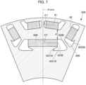
- FIG. 7 is an enlarged view of a portion related to one magnetic pole according to still another embodiment.
- a rotor core 32B of the present embodiment is different from the rotor core 32 of the above embodiment mainly in that the circumferentially inner second magnet holes 322 are replaced with a single second magnet hole 322B (hereinafter also referred to as "central second magnet hole 322B" in order to distinguish it from radially outer second magnet holes 322B).
- the orientation of a permanent magnet 62B in the central second magnet hole 322B is therefore different from the above embodiment.
- the permanent magnet 62B has a smaller separation distance d from the permanent magnet 61 at a circumferential position closer to a second intermediate bridge portion 45B than at a circumferential position farther from the second intermediate bridge portion 45B in the circumferential direction (e.g., a circumferential position on the d-axis). That is, the permanent magnet 62 has a greater separation distance d from the permanent magnet 61 at a circumferentially inner position than at a circumferentially outer position.
- ⁇ 1 > ⁇ 2 are the angles of the extending directions of the permanent magnets 61, 62B with respect to the d-axis, respectively.
- ⁇ 1 > ⁇ 2 and ⁇ 2 is 90 degrees or less (or an angle slightly greater than 90 degrees).
- the second intermediate bridge portion 45B extends radially inward beyond a radially inner edge 6221B of a circumferential end 622B of the permanent magnet 62B facing the second intermediate bridge portion 45B in the circumferential direction, as in the embodiment described above with reference to FIG. 6 .
- a first overhang portion 3221B corresponding to the first overhang portion 3221 and an overhang portion 3223B corresponding to the overhang portion 3223A may be provided.
- the present embodiment also has the same effects as those of the above embodiment.
- a single permanent magnet 62B is provided in the central second magnet hole 322B.
- two or more permanent magnets may be provided so as to be arranged next to each other in the circumferential direction.
- FIG. 8 is an enlarged view of a portion related to one magnetic pole according to yet another embodiment.
- a rotor core 32C according to the present embodiment is different from the rotor core 32 according to the above embodiment in that the circumferentially inner second magnet holes 322 are replaced with second magnet holes 322C.
- the second magnet holes 322C are different in that the above second overhang portion 3222 is replaced with a second overhang portion 3222C.
- the second overhang portion 3222C is different from the above second overhang portion 3222 in position.
- the second magnet holes 322C each have the second overhang portion 3222C at its end farther from the second center bridge portion 44 in the circumferential direction (circumferentially outer end).
- the second overhang portion 3222C extends toward (overhangs) the permanent magnet 62 in the circumferential direction on the radially inner side of the circumferential outer end.
- the second overhang portion 3222 may overlap the permanent magnet 62 with a part 3202C of the rotor core 32 therebetween as viewed in the radial direction.
- the second overhang portion 3222C may be provided in the common second magnet hole 322C on the same radially inner side as the first overhang portion 3221. In this case, the function of the second overhang portion 3222C (function to reduce an increase in back electromotive force) is added, so that an increase in back electromotive force can be effectively reduced.
- the present embodiment also has the same effects as those of the above embodiment.
- the second overhang portion 3222C is provided on the radially inner side of the second magnet hole 322C at the second intermediate bridge portion 45C.
- the second overhang portion 3222C can therefore be advantageous in that the second overhang portion 3222C does not affect the width of a second portion 3212C (magnetic path width) at all.
- the second overhang portion 3222C can be disadvantageous in that the second overhang portion 3222C together with the first overhang portion 3221 may obstruct a magnetic path through a third portion 3213C.
- the second overhang portion 3222 is located diagonally to the first overhang portion 3221. Therefore, the second overhang portion 3222 can be advantageous in that the second overhang portion 3222 does not excessively restrict magnetic flux generated from the permanent magnet 62.
Landscapes
- Engineering & Computer Science (AREA)
- Power Engineering (AREA)
- Permanent Field Magnets Of Synchronous Machinery (AREA)
Abstract
Description
- The present disclosure relates to rotors for rotating electrical machines.
- A technique is known in which a plurality of permanent magnets is arranged in a two-layer structure in a rotor core.
- Patent Document 1:
Japanese Unexamined Patent Application Publication No. 2019-54659 JP 2019-54659 A - However, in the case of such a two-layer structure (same applies to three or more layers), making a bridge relatively thick in order to withstand an increase in centrifugal force associated with an increase in rotational speed of a rotating electrical machine increases leakage magnetic flux through the bridge. Moreover, enlarging the end shape of magnet holes by relatively large rounded corners R etc. in order to reduce stress concentration on the bridge tends to contribute to a decrease in reluctance torque.
- In one aspect, it is an object of the present disclosure to allow an increase in rotational speed of a rotating electrical machine while reducing both a decrease in reluctance torque and stress concentration on a bridge.
- In one aspect, a rotor for a rotating electrical machine is provided that includes: a rotor core having a radially outer first magnet hole and a radially inner second magnet hole;
- a first permanent magnet in the first magnet hole; and
- a second permanent magnet in the second magnet hole.
- The rotor core includes a first portion located radially outward of the first magnet hole, a second portion extending between the first magnet hole and the second magnet hole in such a manner that both sides in a circumferential direction of the second portion extend to an outer peripheral surface of the rotor core, a third portion extending radially inward of the second magnet hole in such a manner that both sides in the circumferential direction of the third portion extend to the outer peripheral surface of the rotor core, and a plurality of bridge portions located radially inward of the outer peripheral surface of the rotor core and connecting the third portion and the second portion.
- The second permanent magnet includes a d-axis-side second permanent magnet located on a d-axis or near the d-axis.
- A separation distance of the d-axis-side second permanent magnet from the first permanent magnet is smaller at a position closer to at least one of the plurality of bridge portions in the circumferential direction than at a position farther from the at least one bridge portion in the circumferential direction along a side of the d-axis-side second permanent magnet that faces the first permanent magnet, as viewed in an axial direction.
- The at least one bridge portion extends radially inward beyond a radially inner edge of a circumferential end of the d-axis-side second permanent magnet facing the at least one bridge portion in the circumferential direction.
- In the one aspect, according to the present disclosure, it is possible to increase the rotational speed of a rotating electrical machine while reducing both a decrease in reluctance torque and stress concentration on a bridge.
-
- [
FIG. 1] FIG. 1 is a sectional view schematically showing a sectional structure of a motor according to an embodiment. - [
FIG. 2] FIG. 2 is a sectional view of a rotor (sectional view taken along a plane perpendicular to an axial direction). - [
FIG. 3] FIG. 3 is an enlarged view of a portion related to one magnetic pole shown inFIG. 2 . - [
FIG. 4] FIG. 4 is a further enlarged view of the portion ofFIG. 3 , showing lines for describing shape features. - [
FIG. 5] FIG. 5 is a diagram illustrating part of effects of the embodiment in comparison with a comparative example. - [
FIG. 6] FIG. 6 is an enlarged view of a portion related to one magnetic pole according to another embodiment. - [
FIG. 7] FIG. 7 is an enlarged view of a portion related to one magnetic pole according to still another embodiment. - [
FIG. 8] FIG. 8 is an enlarged view of a portion related to one magnetic pole according to yet another embodiment. - Embodiments will be described in detail below with reference to the accompanying drawings. The dimensional ratios in the drawings are merely illustrative, and are not limited to these. The shapes etc. in the drawings may be partially exaggerated for convenience of description.
-
FIG. 1 is a sectional view schematically showing a sectional structure of amotor 1 according to an embodiment.FIG. 2 is a sectional view of a rotor 30 (sectional view taken along a plane perpendicular to an axial direction). For simplicity, inFIG. 2 etc., reference signs may be given only to part of a plurality of portions having the same attribute. -
FIG. 1 shows arotation axis 12 of themotor 1. In the following description, the axial direction refers to a direction in which the rotation axis (rotation center) 12 of themotor 1 extends, and the radial direction refers to a radial direction about therotation axis 12. Therefore, "radially outer" and "radially outward" refer to a side away from therotation axis 12, and the "radially inner" and "radially inward" refers to a side toward therotation axis 12. The circumferential direction corresponds to a rotation direction about therotation axis 12. - The
motor 1 may be a vehicle drive motor that is used in, for example, a hybrid electric vehicle or a battery electric vehicle. However, themotor 1 may be used for any other purposes. - The
motor 1 is of an inner rotor type, and astator 21 is provided so as to surround the radially outer side of therotor 30. The radially outer side of thestator 21 is fixed to amotor housing 10. Thestator 21 includes astator core 211 composed of, for example, annular magnetic steel laminations, and a plurality of slots (not shown) around which acoil 22 is wound is provided on the radially inner side of thestator core 211. - The
rotor 30 is disposed radially inward of thestator 21. - The
rotor 30 includes arotor core 32, arotor shaft 34,end plates permanent magnets - The
rotor core 32 is fixed to the radially outer surface of therotor shaft 34 and rotates with therotor shaft 34. Therotor core 32 has a shaft hole 320 (seeFIG. 2 ), and therotor shaft 34 is fitted in theshaft hole 320. Therotor core 32 may be fixed to therotor shaft 34 by shrink fitting, press fitting, or the like. For example, therotor core 32 may be coupled to therotor shaft 34 by key coupling or spline coupling. Therotor shaft 34 is rotatably supported by themotor housing 10 viabearings rotor shaft 34 defines therotation axis 12 of themotor 1. - The
rotor core 32 is composed of, for example, annular magnetic steel laminations. Thepermanent magnets 61, 62 (seeFIG. 2 ) are embedded in therotor core 32. That is, therotor core 32 hasmagnet holes 321, 322 (seeFIG. 2 ) extending through therotor core 32 in the axial direction, and thepermanent magnets magnet holes rotor core 32 may be made of a green compact obtained by pressing and compacting magnetic powder. - The
rotor core 32 is designed in a circular shape having a first radius r1, and the outer peripheral surface of therotor core 32 includes portions having the first radius r1 (outerperipheral surface portions 328B,parts 328C, etc., which will be described later). In the present embodiment, an outerperipheral surface 328 of therotor core 32 has the first radius r1. In a modification, the circular shape of therotor core 32 does not have to be a perfect circle, and may be, for example, a circular shape having a cut in its part. - As shown in
FIG. 2 , therotor core 32 has a rotationally symmetric form about therotation axis 12 as viewed in the axial direction. In the example shown inFIG. 2 , therotor core 32 has a form in which thepermanent magnets rotor core 32 rotates by 45 degrees about therotation axis 12. - The plurality of
permanent magnets FIG. 2 , the plurality ofpermanent magnets permanent magnets 61 and pairs of thepermanent magnets 62 as viewed in the axial direction. In this case, a common magnetic pole is formed between a pair ofpermanent magnets 61 and between a pair ofpermanent magnets 62. The plurality ofpermanent magnets permanent magnets permanent magnets permanent magnets - Although
FIG. 1 shows themotor 1 having a specific structure, the structure of themotor 1 is not limited to such a specific structure. For example, inFIG. 1 , therotor shaft 34 is hollow. However, therotor shaft 34 may be solid. - Next, the
rotor core 32 and thepermanent magnets FIG. 3 and the subsequent figures. Although the configuration related to one magnetic pole will be described below, the same may apply to the configurations related to the other magnetic poles. -
FIG. 3 is an enlarged view of a portion related to one magnetic pole shown inFIG. 2 . The configuration related to one magnetic pole is basically symmetrical with respect to a d-axis (shown by "d-axis" in English inFIG. 3 ). Hereinafter, "circumferentially outer" and "circumferentially outward" refer to a side away from the d-axis, and the "circumferentially inner" and "circumferentially inward" refers to a side toward the d-axis. - The
rotor core 32 has the radially outer magnet holes 321 (hereinafter referred to as "first magnet holes 321") and the radially inner magnet holes 322 (hereinafter referred to as "second magnet holes 322"). - The first magnet holes 321 are provided in a pair such that the two first magnet holes 321 of the pair form a substantially V-shape (substantially V-shape that opens radially outward or radially inward). In a modification, the first magnet holes 321 may be provided in a pair such that the two first magnet holes 321 of the pair form a straight line shape, or the straight line shape may be implemented by a single straight hole (having a straight line shape perpendicular to the d-axis). A
permanent magnet 61 is provided in eachfirst magnet hole 321. A clearance may be provided between thefirst magnet hole 321 and thepermanent magnet 61 at both longitudinal ends of thepermanent magnet 61. The clearance may be an empty space or may be filled with resin etc. - The second magnet holes 322 are provided radially inward of the first magnet holes 321. Like the first magnet holes 321, the second magnet holes 322 are provided in a pair symmetrical with respect to the d axis. The second magnet holes 322 on both sides of the d axis in the circumferential direction extend in a wider range in the circumferential direction than the first magnet holes 321 on both sides of the d axis in the circumferential direction. A
permanent magnet 62 is provided in eachsecond magnet hole 322. A clearance may be provided between thesecond magnet hole 322 and thepermanent magnet 62 at both longitudinal ends of thepermanent magnet 62. The clearance may be an empty space or may be filled with resin etc. - In the present embodiment, two second magnet holes 322 are provided on one side in the circumferential direction of the d-axis, and two second magnet holes 322 are provided on the other side in the circumferential direction of the d-axis. That is, a total of four second magnet holes 322 are provided for one magnetic pole.
- Since the
rotor core 32 has such first magnet holes 321 and second magnet holes 322, therotor core 32 has threeportions first portion 3211," "second portion 3212," and "third portion 3213"). - Specifically, the
first portion 3211 extends radially outward of the first magnet holes 321. Thefirst portion 3211 forms apart 328A (seeFIG. 3 ) of the outerperipheral surface 328 of therotor core 32. - The
second portion 3212 extends between the second magnet holes 322 and the first magnet holes 321 such that both sides in the circumferential direction of thesecond portion 3212 extend to the outerperipheral surface 328 of therotor core 32. Thesecond portion 3212forms parts 328B of the outerperipheral surface 328 of the rotor core 32 (hereinafter also referred to as "outerperipheral surface portions 328B of thesecond portion 3212") (seeFIG. 3 ) on both sides in the circumferential direction of thefirst portion 3211. Thesecond portion 3212 forms a magnetic path for q-axis magnetic flux. Specifically, the q-axis magnetic flux flows between the second magnet holes 322 and the first magnet holes 321 from one end (outerperipheral surface portion 328B on one side) toward the other end (outerperipheral surface portion 328B on the other side) of thesecond portion 3212. - The
third portion 3213 extends radially inward of the second magnet holes 322 such that both sides in the circumferential direction of thethird portion 3213 extend to the outerperipheral surface 328 of therotor core 32. Thethird portion 3213forms parts 328C (seeFIG. 3 ) of the outerperipheral surface 328 of therotor core 32 on both sides in the circumferential direction of thesecond portion 3212. - In the present embodiment, the mass of the
third portion 3213 is significantly larger than the mass of thesecond portion 3212, and the mass of thesecond portion 3212 is significantly larger than the mass of thefirst portion 3211. - Since the
rotor core 32 has such threeportions rotor core 32 has a plurality ofbridge portions portions - The bridge portions 41 (hereinafter referred to as "
first bridge portions 41") support thefirst portion 3211 radially outward of thesecond portion 3212. That is, thefirst bridge portions 41 connect thesecond portion 3212 and thefirst portion 3211 and extend in the circumferential direction. Thefirst bridge portions 41 are provided in a pair on both sides in the circumferential direction of (circumferentially outward of) thefirst portion 3211. - The bridge portions 42 (hereinafter referred to as "
second bridge portions 42") support thesecond portion 3212 radially outward of thethird portion 3213. That is, thesecond bridge portions 42 connect thethird portion 3213 and thesecond portion 3212 and extend in the circumferential direction. Thesecond bridge portions 42 are provided in a pair on both sides in the circumferential direction of (circumferentially outward of) thesecond portion 3212. - The bridge portion 43 (hereinafter referred to as "first
center bridge portion 43") supports thefirst portion 3211 on the d-axis with respect to thesecond portion 3212. - The bridge portion 44 (hereinafter referred to as "second
center bridge portion 44") supports thesecond portion 3212 on the d-axis with respect to thethird portion 3213. - The bridge portions 45 (hereinafter referred to as the "second
intermediate bridge portions 45") each support thesecond portion 3212 between two second magnet holes 322 with respect to thethird portion 3213. - Next, characteristic configurations of the present embodiment will be described with reference to
FIG. 4 and the subsequent figures.FIG. 4 is a further enlarged view of the portion ofFIG. 3 , showing lines for describing shape features.FIG. 5 is a diagram illustrating part of effects of the present embodiment in comparison with a comparative example. InFIG. 5 , the comparative example is shown on the right side, the present embodiment is shown on the left side, and the flow of the q-axis magnetic flux in the comparative example and the present embodiment is schematically shown by arrows R5, R5', respectively. In the following description related toFIGS. 4 and5 , the second magnet holes 322 and thepermanent magnets 62 refer to the circumferentially inner second magnet holes 322 andpermanent magnets 62 out of the circumferentially outer and circumferentially inner second magnet holes 322 andpermanent magnets 62, unless otherwise specified. - In the present embodiment, as shown in
FIG. 4 , thepermanent magnets 62 each have a smaller separation distance d from thepermanent magnet 61 at a circumferential position closer to the secondcenter bridge portion 44 than at a circumferential position farther from the secondcenter bridge portion 44 in the circumferential direction along aside 624 of thepermanent magnet 62 that faces thepermanent magnet 61, as viewed in the axial direction. That is, thepermanent magnets 62 each have a smaller separation distance d from thepermanent magnet 61 at a circumferentially inner position than at a circumferentially outer position. InFIG. 4 , for convenience, the separation distances d of thepermanent magnet 62 from thepermanent magnet 61 at the circumferentially inner position on thepermanent magnet 62 and at the circumferentially outer position on thepermanent magnet 62 are denoted by d(1) and d(2), respectively, for a distinguishing purpose. The separation distance d may be a distance perpendicular to theside 624 of thepermanent magnet 62 that faces thepermanent magnet 61, as viewed in the axial direction. The separation distance d between thepermanent magnet 62 and thepermanent magnet 61 is a separation distance in a plane perpendicular to the axial direction (i.e., a separation distance in a plane including the plane of paper ofFIG. 4 ), and corresponds to the width of the second portion 3212 (magnetic path width). Such a relationship in magnitude between the separation distances d tends to occur when α1 < α2, where α1 and α2 are the angles of the extending directions of thepermanent magnets - In this case, the
permanent magnets 62 in the two adjacent second magnet holes 322 with the secondcenter bridge portion 44 interposed therebetween in the circumferential direction may be each disposed in such an orientation that the side of thepermanent magnet 62 that is closer to the d-axis in the circumferential direction is located radially outward of the side of thepermanent magnet 62 that is farther from the d-axis in the circumferential direction. That is, thepermanent magnets 62 in the two adjacent second magnet holes 322 with the secondcenter bridge portion 44 interposed therebetween in the circumferential direction may be arranged in a V-shape pointing radially outward. In this case, compared to the case where thepermanent magnets 61 are arranged in a V-shape pointing radially inward, the amount of thesecond portion 3212 can be relatively reduced without significantly reducing the width of the second portion 3212 (magnetic path width). As a result, it is possible to reduce stress (radially outward tensile stress) that is applied to the secondcenter bridge portion 44 and the secondintermediate bridge portions 45 due to the centrifugal force that is generated during rotation of therotor 30. - In the present embodiment, the second
center bridge portion 44 extends radially inward beyond radiallyinner edges 6211 of circumferential ends 621 of thepermanent magnets 62 facing the secondcenter bridge portion 44 in the circumferential direction. In other words, when a line segment L2 connecting the radially inner (and circumferentially inner) vertices of the two adjacentpermanent magnets 62 with the d-axis interposed therebetween in the circumferential direction is used as a reference, the secondcenter bridge portion 44 extends radially inward beyond the line segment L2. On the other hand, the secondcenter bridge portion 44 does not extend radially outward beyond radiallyouter edges 6212 of the circumferential ends 621 of thepermanent magnets 62 facing the secondcenter bridge portion 44 in the circumferential direction. In other words, when a line segment L1 connecting the radially outer (and circumferentially inner) vertices of the two adjacentpermanent magnets 62 with the d-axis interposed therebetween in the circumferential direction is used as a reference, the secondcenter bridge portion 44 does not extend radially outward beyond the line segment L1. - As described above, in the present embodiment, the radial length of the second
center bridge portion 44 is significantly larger than the radial width d0 of thepermanent magnets 62, and extends radially inward beyond the circumferential ends 621 of thepermanent magnets 62. In this case, rounded corners R1, R2 on both radial sides of the secondcenter bridge portion 44 can be made relatively large. This can effectively reduce stress concentration (stress concentration due to the centrifugal force) on both radial ends of the secondcenter bridge portion 44. In other words, it is possible to reduce the width d1 of the second center bridge portion 44 (and reduce leakage magnetic flux through the second center bridge portion 44) without increasing stress on both radial ends of the secondcenter bridge portion 44. - In the present embodiment, the second
center bridge portion 44 is extended radially inward beyond the line segment L2 in order to increase the radial length of the secondcenter bridge portion 44. This can reduce a disadvantage that tends to occur in the comparative example (see rotor core 32' inFIG. 5 ) in which a second center bridge portion 44' is extended radially outward beyond the above line segment L1 (seeFIG. 4 ) in order to increase the radial length of the second center bridge portion 44'. Specifically, in the comparative example in which the second center bridge portion 44' extends radially outward beyond the above line segment L1 (seeFIG. 4 ) as shown inFIG. 5 , the width of a second portion 3212' (magnetic path width) is reduced accordingly. This is because the radially outward extension of the second center bridge portion 44' is accompanied by radially outward extension of second magnet holes 322' located circumferentially outward of the second center bridge portion 44'. In this case, the reduction in width of the second portion 3212' (magnetic path width) causes a decrease in reluctance torque. On the other hand, according to the present embodiment, the radial length of the secondcenter bridge portion 44 is increased without causing the secondcenter bridge portion 44 to extend radially outward beyond the line segment L1, as described above. Therefore, the width of the second portion 3212 (magnetic path width) is not reduced due to the secondcenter bridge portion 44. - According to the present embodiment, since the radial length of the second
center bridge portion 44 is increased, it is possible to reduce stress concentration on the second center bridge portion 44 (and as a result, increase the rotational speed of the motor 1) and to effectively prevent a decrease in reluctance torque (decrease in width of the second portion 3212) due to the increase in radial length of the secondcenter bridge portion 44. - In the present embodiment, the second magnet holes 322 each have a
first overhang portion 3221 at its end closer to the secondcenter bridge portion 44 in the circumferential direction (hereinafter also simply referred to as "circumferentially inner end 322-1"). Thefirst overhang portion 3221 extends toward (overhangs) thepermanent magnet 62 in the circumferential direction on the radially inner side of the circumferentially inner end 322-1. In this case, thefirst overhang portion 3221 may overlap thepermanent magnet 62 with apart 3201 of therotor core 32 therebetween as viewed in the radial direction. Thefirst overhang portion 3221 is formed so as to be continuous from the rounded corner R2, forms a rounded corner R3, and then terminates with a rounded corner R4 near the vertex on the radially inner side and circumferentially inner side of thepermanent magnet 62. Such afirst overhang portion 3221 has a function to reduce an increase in back electromotive voltage. - In the present embodiment, the second magnet holes 322 each have a
second overhang portion 3222 at its end farther from the secondcenter bridge portion 44 in the circumferential direction (hereinafter also simply referred to as "circumferentially outer end 322-2"). Thesecond overhang portion 3222 extends toward (overhangs) thepermanent magnet 62 in the circumferential direction on the radially outer side of the circumferentially outer end 322-2. In this case, thesecond overhang portion 3222 may overlap thepermanent magnet 62 with apart 3202 of therotor core 32 therebetween as viewed in the radial direction. As described above, thesecond overhang portion 3222 may be provided in the commonsecond magnet hole 322 in a diagonal positional relationship with thefirst overhang portion 3221. In this case, the function of the second overhang portion 3222 (function to reduce an increase in back electromotive force) is added, so that an increase in back electromotive force can be effectively reduced. - Since the
second overhang portion 3222 enlarges thesecond magnet hole 322 toward the second portion 3212 (i.e., causes the secondintermediate bridge portion 45 to extend radially outward beyond the permanent magnet 62), the width of the second portion 3212 (magnetic path width) may be reduced depending on the shape of thesecond overhang portion 3222 etc. Therefore, thesecond overhang portion 3222 is preferably formed so as not to significantly reduce the width of the second portion 3212 (magnetic path width). Particularly in the present embodiment, as described above, the separation distance d between thepermanent magnet 62 and thepermanent magnet 61 is greater at a circumferentially outer position on thepermanent magnet 62 than at a circumferentially inner position on thepermanent magnet 62. Therefore, forming thesecond overhang portion 3222 at a circumferentially outer position on thepermanent magnet 62 rather than at a circumferentially inner position on thepermanent magnet 62 makes it easier to allow thesecond portion 3212 to have a necessary width (magnetic path width). - In the present embodiment, the circumferentially outer second magnet holes 322 each also have an
overhang portion 3223 in such a manner that theoverhang portion 3223 faces thesecond overhang portion 3222 in the circumferential direction. In this case, the function of the overhang portion 3223 (function to reduce an increase in back electromotive force) is added, so that an increase in back electromotive force can be effectively reduced. - Next, some other embodiments will be described with reference to
FIG. 6 and the subsequent figures. -
FIG. 6 is an enlarged view of a portion related to one magnetic pole according to another embodiment. In the following description ofFIG. 6 as well, second magnet holes 322A andpermanent magnets 62 refer to the circumferentially inner second magnet holes 322A andpermanent magnets 62, unless otherwise specified. - A
rotor core 32A according to the present embodiment is different from therotor core 32 according to the above embodiment mainly in that the second magnet holes 322 are replaced with the second magnet holes 322A. The second magnet holes 322A are different from the second magnet holes 322 mainly in orientation (angle α2), and therefore the orientations of thepermanent magnets 62 in the second magnet holes 322A are different from the above embodiment. - Specifically, in the present embodiment, the
permanent magnets 62 each have a smaller separation distance d from thepermanent magnet 61 at a circumferential position closer to a secondintermediate bridge portion 45A than at a circumferential position farther from the secondintermediate bridge portion 45A. That is, thepermanent magnets 62 each have a greater separation distance d from thepermanent magnet 61 at a circumferentially inner position than at a circumferentially outer position. Such a relationship in magnitude between the separation distances d tends to occur when α1 > α2, where α1 and α2 are the angles of the extending directions of thepermanent magnets - In the present embodiment, the second
intermediate bridge portion 45A extends radially inward beyond radiallyinner edges 6221 of circumferential ends 622 of thepermanent magnets 62 facing the secondintermediate bridge portion 45A in the circumferential direction. In other words, when a line segment L4 connecting the radially inner (and circumferentially opposing) vertices of the twopermanent magnets 62 located on one side in the circumferential direction with respect to the d-axis is used as a reference, the secondintermediate bridge portion 45A extends radially inward beyond the line segment L4. On the other hand, the secondintermediate bridge portion 45A does not extend radially outward beyond radiallyouter edges 6221 of the circumferential ends 622 of thepermanent magnets 62 facing the secondintermediate bridge portion 45A in the circumferential direction. In other words, when a line segment L3 connecting the radially outer (and circumferentially opposing) vertices of the twopermanent magnets 62 located on the one side in the circumferential direction with respect to the d-axis is used as a reference, the secondintermediate bridge portion 45A does not extend radially outward beyond the line segment L3. - As described above, in the present embodiment, the radial length of the second
intermediate bridge portion 45A is significantly larger than the radial width d0 of thepermanent magnet 62, and extends radially inward beyond thepermanent magnets 62. In this case, rounded corners R11, R12 on both radial sides of the secondintermediate bridge portion 45A can be made relatively large. This can effectively reduce stress concentration (stress concentration due to the centrifugal force) on both radial ends of the secondintermediate bridge portion 45A. In other words, it is possible to reduce the width d10 of the secondintermediate bridge portion 45A (and reduce leakage magnetic flux through the secondintermediate bridge portion 45A) without increasing stress on both radial ends of the secondintermediate bridge portion 45A. - In the present embodiment, the radial length of the second
intermediate bridge portion 45A is increased by causing the secondintermediate bridge portion 45A to extend radially inward beyond the line segment L4. This can reduce a disadvantage that tends to occur when the secondintermediate bridge portion 45A is extended radially outward beyond the line segment L3 (not shown). Specifically, as can be seen fromFIG. 6 and the above description, when the secondintermediate bridge portion 45A extends radially outward beyond the above line segment L3, the width of asecond portion 3212A (magnetic path width) is reduced accordingly. In this case, the reduction in width of thesecond portion 3212A (magnetic path width) causes a decrease in reluctance torque. On the other hand, according to the present embodiment, the secondintermediate bridge portion 45A is extended radially inward beyond the line segment L4 without being extended radially outward beyond the line segment L3, as described above. Therefore, the width of thesecond portion 3212A (magnetic path width) is not reduced due to the secondintermediate bridge portion 45A. - According to the present embodiment, since the radial length of the second
intermediate bridge portion 45A is increased, it is possible to reduce stress concentration on the secondintermediate bridge portion 45A (and as a result, increase the rotational speed of the motor 1) and to effectively prevent a decrease in reluctance torque (decrease in width of thesecond portion 3212A) due to the increase in radial length of the secondintermediate bridge portion 45A. - In the present embodiment, the second magnet holes 322A each have a
first overhang portion 3221A at its end closer to the secondintermediate bridge portion 45A in the circumferential direction (hereinafter also simply referred to as "circumferentially outer end 322-3"). Thefirst overhang portion 3221A extends toward (overhangs) thepermanent magnet 62 in the circumferential direction on the radially inner side of the circumferentiallyouter end 322. In this case, thefirst overhang portion 3221A may overlap thepermanent magnet 62 with a part 3201A of therotor core 32 therebetween as viewed in the radial direction. Thefirst overhang portion 3221A is formed so as to be continuous from the rounded corner R12, forms a rounded corner R13, and then terminates with a rounded corner R14 near the vertex on the radially inner side and circumferentially inner side of thepermanent magnet 62. Thefirst overhang portion 3221A has a function to reduce an increase in back electromotive voltage. - In the present embodiment, the second magnet holes 322A each have a
second overhang portion 3222A at its end farther from the secondintermediate bridge portion 45A in the circumferential direction (hereinafter also simply referred to as "circumferentially inner end 322-4"). Thesecond overhang portion 3222A extends toward (overhangs) thepermanent magnet 62 in the circumferential direction on the radially outer side of the circumferential inner end 322-4. In this case, thesecond overhang portion 3222A may overlap thepermanent magnet 62 with apart 3202A of therotor core 32 therebetween as viewed in the radial direction. As described above, thesecond overhang portion 3222A may be provided in the commonsecond magnet hole 322A in a diagonal positional relationship with thefirst overhang portion 3221. In this case, the function of thesecond overhang portion 3222A (function to reduce an increase in back electromotive force) is added, so that an increase in back electromotive force can be effectively reduced. - Since the
second overhang portion 3222A enlarges thesecond magnet hole 322A toward thesecond portion 3212A (i.e., causes the secondcenter bridge portion 44 to extend radially outward beyond the permanent magnet 62), the width of thesecond portion 3212A (magnetic path width) may be reduced depending on the shape of thesecond overhang portion 3222A etc. Therefore, thesecond overhang portion 3222A is preferably formed so as not to significantly reduce the width of thesecond portion 3212A (magnetic path width). Particularly in the present embodiment, as described above, the separation distance d between thepermanent magnet 62 and thepermanent magnet 61 is greater at a circumferential inner position on thepermanent magnet 62 than at a circumferentially outer position on thepermanent magnet 62. Therefore, forming thesecond overhang portion 3222A at a circumferentially inner position on thepermanent magnet 62 rather than at a circumferentially outer position on thepermanent magnet 62 makes it easier to allow thesecond portion 3212A to have a necessary width (magnetic path width). - In the present embodiment, the circumferentially outer second magnet holes 322A each also have an
overhang portion 3223A in such a manner that theoverhang portion 3223A faces thefirst overhang portion 3221A in the circumferential direction. In this case, the function of theoverhang portion 3223A (function to reduce an increase in back electromotive force) is added, so that an increase in back electromotive force can be effectively reduced. - The present embodiment also has the same effects as those of the above embodiment.
-
FIG. 7 is an enlarged view of a portion related to one magnetic pole according to still another embodiment. - A
rotor core 32B of the present embodiment is different from therotor core 32 of the above embodiment mainly in that the circumferentially inner second magnet holes 322 are replaced with a singlesecond magnet hole 322B (hereinafter also referred to as "centralsecond magnet hole 322B" in order to distinguish it from radially outer second magnet holes 322B). The orientation of apermanent magnet 62B in the centralsecond magnet hole 322B is therefore different from the above embodiment. - Specifically, in the present embodiment, the
permanent magnet 62B has a smaller separation distance d from thepermanent magnet 61 at a circumferential position closer to a secondintermediate bridge portion 45B than at a circumferential position farther from the secondintermediate bridge portion 45B in the circumferential direction (e.g., a circumferential position on the d-axis). That is, thepermanent magnet 62 has a greater separation distance d from thepermanent magnet 61 at a circumferentially inner position than at a circumferentially outer position. Such a relationship in magnitude between the separation distances d tends to occur when α1 > α2, where α1 and α2 are the angles of the extending directions of thepermanent magnets - Accordingly, in the present embodiment as well, the second
intermediate bridge portion 45B extends radially inward beyond a radiallyinner edge 6221B of acircumferential end 622B of thepermanent magnet 62B facing the secondintermediate bridge portion 45B in the circumferential direction, as in the embodiment described above with reference toFIG. 6 . - In the present embodiment as well, as in the embodiment described above with reference to
FIG. 6 , afirst overhang portion 3221B corresponding to thefirst overhang portion 3221 and anoverhang portion 3223B corresponding to theoverhang portion 3223A may be provided. - The present embodiment also has the same effects as those of the above embodiment. In the example shown in
FIG. 7 , a singlepermanent magnet 62B is provided in the centralsecond magnet hole 322B. However, instead of a singlepermanent magnet 62B, two or more permanent magnets may be provided so as to be arranged next to each other in the circumferential direction. -
FIG. 8 is an enlarged view of a portion related to one magnetic pole according to yet another embodiment. - A
rotor core 32C according to the present embodiment is different from therotor core 32 according to the above embodiment in that the circumferentially inner second magnet holes 322 are replaced with second magnet holes 322C. The second magnet holes 322C are different in that the abovesecond overhang portion 3222 is replaced with asecond overhang portion 3222C. Thesecond overhang portion 3222C is different from the abovesecond overhang portion 3222 in position. - Specifically, the second magnet holes 322C each have the
second overhang portion 3222C at its end farther from the secondcenter bridge portion 44 in the circumferential direction (circumferentially outer end). Thesecond overhang portion 3222C extends toward (overhangs) thepermanent magnet 62 in the circumferential direction on the radially inner side of the circumferential outer end. In this case, thesecond overhang portion 3222 may overlap thepermanent magnet 62 with apart 3202C of therotor core 32 therebetween as viewed in the radial direction. As described above, thesecond overhang portion 3222C may be provided in the commonsecond magnet hole 322C on the same radially inner side as thefirst overhang portion 3221. In this case, the function of thesecond overhang portion 3222C (function to reduce an increase in back electromotive force) is added, so that an increase in back electromotive force can be effectively reduced. - The present embodiment also has the same effects as those of the above embodiment. In the present embodiment, however, the
second overhang portion 3222C is provided on the radially inner side of thesecond magnet hole 322C at the secondintermediate bridge portion 45C. Thesecond overhang portion 3222C can therefore be advantageous in that thesecond overhang portion 3222C does not affect the width of asecond portion 3212C (magnetic path width) at all. However, thesecond overhang portion 3222C can be disadvantageous in that thesecond overhang portion 3222C together with thefirst overhang portion 3221 may obstruct a magnetic path through athird portion 3213C. In other words, in therotor core 32 according to the above embodiment (seeFIG. 3 ), thesecond overhang portion 3222 is located diagonally to thefirst overhang portion 3221. Therefore, thesecond overhang portion 3222 can be advantageous in that thesecond overhang portion 3222 does not excessively restrict magnetic flux generated from thepermanent magnet 62. - Although the embodiments are described in detail above, the present disclosure is not limited to the specific embodiments, and various modifications and changes can be made within the scope of the claims. It is also possible to combine all or part of the constituent elements of the embodiments described above.
- 1 ... motor (rotating electrical machine), 30 ... rotor, 32, 32A, 32B, 32C ... rotor core, 328 ... outer peripheral surface, 3211 ... first portion, 3212, 3212A, 3212C ... second portion, 3213 ... third portion, 44 ... second center bridge portion (at least one bridge portion, center bridge portion), 45A, 45B ... second intermediate bridge portion (at least one bridge portion, intermediate bridge portion), 321 ... first magnet hole, 61 ... permanent magnet (first permanent magnet), 62 ... permanent magnet (second permanent magnet), 322, 322A, 322B, 322C ... second magnet hole, 322-1 ... circumferentially inner end (first end), 322-2 ... circumferential outer end (second end), 322-3 ... circumferentially outer end (first end), 322-4 ... circumferentially inner end (second end), 3221, 3221A ... first overhang portion, 3222, 3222A, 3222C ... second overhang portion
Claims (7)
- A rotor for a rotating electrical machine, the rotor comprising:a rotor core having a radially outer first magnet hole and a radially inner second magnet hole;a first permanent magnet in the first magnet hole; anda second permanent magnet in the second magnet hole, whereinthe rotor core includes a first portion located radially outward of the first magnet hole, a second portion extending between the first magnet hole and the second magnet hole in such a manner that both sides in a circumferential direction of the second portion extend to an outer peripheral surface of the rotor core, a third portion extending radially inward of the second magnet hole in such a manner that both sides in the circumferential direction of the third portion extend to the outer peripheral surface of the rotor core, and a plurality of bridge portions located radially inward of the outer peripheral surface of the rotor core and connecting the third portion and the second portion,the second permanent magnet includes a d-axis-side second permanent magnet located on a d-axis or near the d-axis,a separation distance of the d-axis-side second permanent magnet from the first permanent magnet is smaller at a position closer to at least one of the plurality of bridge portions in the circumferential direction than at a position farther from the at least one bridge portion in the circumferential direction along a side of the d-axis-side second permanent magnet that faces the first permanent magnet, as viewed in an axial direction, andthe at least one bridge portion extends radially inward beyond a radially inner edge of a circumferential end of the d-axis-side second permanent magnet facing the at least one bridge portion in the circumferential direction.
- The rotor for a rotating electrical machine according to claim 1, wherein for a pair of the second permanent magnets in adjacent two of the second magnet holes with the at least one bridge portion interposed between the two second magnet holes in the circumferential direction, when a line segment connecting radially inner and circumferentially opposing vertices of the pair of the second permanent magnets is used as a reference, the at least one bridge portion terminates radially inward of the line segment.
- The rotor for a rotating electrical machine according to claim 1, whereintwo of the second magnet holes and two of the second magnet holes are provided on each side in the circumferential direction of the d-axis for each magnetic pole,the plurality of bridge portions includes a center bridge portion extending in a radial direction so as to extend on the d-axis, and an intermediate bridge extending at a position away from the d-axis in the circumferential direction, andthe at least one bridge portion is the center bridge portion or the intermediate bridge.
- The rotor for a rotating electrical machine according to claim 3, whereinthe at least one bridge portion is the center bridge portion, andthe second magnet holes and the second permanent magnets are configured symmetrically with respect to the d-axis.
- The rotor for a rotating electrical machine according to claim 4, wherein
each of the second permanent magnets in adjacent two of the second magnet holes with the center bridge portion interposed between the two second magnet holes in the circumferential direction is disposed in such an orientation that a side of the second permanent magnet that is closer to the d-axis in the circumferential direction is located radially outward of a side of the second permanent magnet that is farther from the d-axis in the circumferential direction. - The rotor for a rotating electrical machine according to claim 4 or 5, whereinthe second magnet hole adjacent to the center bridge portion in the circumferential direction includes a first overhang portion at a first end of the second magnet hole that is located closer to the center bridge portion in the circumferential direction, andthe first overhang portion extends toward the second permanent magnet in the second magnet hole in the circumferential direction on a radially inner side of the first end, and overlaps the second permanent magnet in the second magnet hole as viewed in the radial direction.
- The rotor for a rotating electrical machine according to claim 6, whereinthe second magnet hole adjacent to the center bridge portion in the circumferential direction includes a second overhang portion at a second end of the second magnet hole that is located farther from the center bridge portion in the circumferential direction, andthe second overhang portion extends toward the second permanent magnet in the second magnet hole in the circumferential direction on a radially outer side of the second end, and overlaps the second permanent magnet in the second magnet hole as viewed in the radial direction.
Applications Claiming Priority (2)
| Application Number | Priority Date | Filing Date | Title |
|---|---|---|---|
| JP2022055379 | 2022-03-30 | ||
| PCT/JP2023/012384 WO2023190446A1 (en) | 2022-03-30 | 2023-03-28 | Rotating electric machine rotor |
Publications (2)
| Publication Number | Publication Date |
|---|---|
| EP4443707A1 true EP4443707A1 (en) | 2024-10-09 |
| EP4443707A4 EP4443707A4 (en) | 2025-04-09 |
Family
ID=88202530
Family Applications (1)
| Application Number | Title | Priority Date | Filing Date |
|---|---|---|---|
| EP23780455.4A Withdrawn EP4443707A4 (en) | 2022-03-30 | 2023-03-28 | ROTOR OF ROTATING ELECTRIC MACHINE |
Country Status (5)
| Country | Link |
|---|---|
| US (1) | US20250070605A1 (en) |
| EP (1) | EP4443707A4 (en) |
| JP (1) | JP7800660B2 (en) |
| CN (1) | CN118805316A (en) |
| WO (1) | WO2023190446A1 (en) |
Family Cites Families (8)
| Publication number | Priority date | Publication date | Assignee | Title |
|---|---|---|---|---|
| JP6079132B2 (en) * | 2012-10-26 | 2017-02-15 | 株式会社ジェイテクト | Embedded magnet rotor |
| JP6147661B2 (en) * | 2013-12-27 | 2017-06-14 | 日立オートモティブシステムズ株式会社 | Rotor, permanent magnet type rotating electric machine including the same, electric drive system, electric vehicle |
| JP2017050965A (en) * | 2015-09-01 | 2017-03-09 | 日産自動車株式会社 | Rotor structure of rotating electrical machine |
| GB201619856D0 (en) * | 2016-11-24 | 2017-01-11 | Jaguar Land Rover Ltd | Electric machine apparatus |
| GB201619857D0 (en) * | 2016-11-24 | 2017-01-11 | Jaguar Land Rover Ltd | Electric machine apparatus |
| JP6879140B2 (en) | 2017-09-15 | 2021-06-02 | トヨタ自動車株式会社 | Rotating machine |
| DE102018128146A1 (en) * | 2018-11-09 | 2020-05-14 | Brusa Elektronik Ag | Rotor for a synchronous drive motor |
| CN111200324B (en) * | 2020-01-16 | 2021-09-28 | 中国第一汽车股份有限公司 | Motor rotor punching sheet, motor rotor, motor and new energy vehicle |
-
2023
- 2023-03-28 JP JP2024512519A patent/JP7800660B2/en active Active
- 2023-03-28 US US18/726,227 patent/US20250070605A1/en active Pending
- 2023-03-28 WO PCT/JP2023/012384 patent/WO2023190446A1/en not_active Ceased
- 2023-03-28 EP EP23780455.4A patent/EP4443707A4/en not_active Withdrawn
- 2023-03-28 CN CN202380023687.8A patent/CN118805316A/en active Pending
Also Published As
| Publication number | Publication date |
|---|---|
| WO2023190446A1 (en) | 2023-10-05 |
| JPWO2023190446A1 (en) | 2023-10-05 |
| CN118805316A (en) | 2024-10-18 |
| US20250070605A1 (en) | 2025-02-27 |
| EP4443707A4 (en) | 2025-04-09 |
| JP7800660B2 (en) | 2026-01-16 |
Similar Documents
| Publication | Publication Date | Title |
|---|---|---|
| CN104937815B (en) | Permanent magnet type rotating electric machine | |
| EP4220899A1 (en) | Rotor core | |
| US12283848B2 (en) | Rotor for rotary electric machine | |
| US12519356B2 (en) | Rotor and rotating electric machine | |
| JP2026003066A (en) | Rotor and rotary electric machine | |
| US20240333053A1 (en) | Rotor and rotating electric machine | |
| US20250070605A1 (en) | Rotor for rotating electrical machine | |
| US12573900B2 (en) | Rotor and rotating electric machine | |
| US20230291255A1 (en) | Rotor of rotary electrical machine | |
| EP4607764A1 (en) | Rotor for rotating electric machine | |
| EP4664726A1 (en) | Rotor for rotating electric machine | |
| EP4607765A1 (en) | Rotor for rotary electric machine | |
| JP2023102517A (en) | Rotor and rotary electric machine | |
| EP4668544A1 (en) | Rotating electric machine rotor | |
| EP4718685A1 (en) | Rotor for rotary electric machine | |
| US12301058B2 (en) | Rotor having end magnet fixed by fixing member | |
| JP7740478B1 (en) | Rotors, electric motors, and compressors | |
| JP3897567B2 (en) | Outer rotor motor | |
| US20230187988A1 (en) | Rotor of rotary electric machine | |
| JP2023061580A (en) | Rotor for rotary electric machine | |
| CN116584019A (en) | rotating electrical machine |
Legal Events
| Date | Code | Title | Description |
|---|---|---|---|
| STAA | Information on the status of an ep patent application or granted ep patent |
Free format text: STATUS: THE INTERNATIONAL PUBLICATION HAS BEEN MADE |
|
| PUAI | Public reference made under article 153(3) epc to a published international application that has entered the european phase |
Free format text: ORIGINAL CODE: 0009012 |
|
| STAA | Information on the status of an ep patent application or granted ep patent |
Free format text: STATUS: REQUEST FOR EXAMINATION WAS MADE |
|
| 17P | Request for examination filed |
Effective date: 20240703 |
|
| AK | Designated contracting states |
Kind code of ref document: A1 Designated state(s): AL AT BE BG CH CY CZ DE DK EE ES FI FR GB GR HR HU IE IS IT LI LT LU LV MC ME MK MT NL NO PL PT RO RS SE SI SK SM TR |
|
| A4 | Supplementary search report drawn up and despatched |
Effective date: 20250307 |
|
| RIC1 | Information provided on ipc code assigned before grant |
Ipc: H02K 1/276 20220101AFI20250303BHEP |
|
| DAV | Request for validation of the european patent (deleted) | ||
| DAX | Request for extension of the european patent (deleted) | ||
| STAA | Information on the status of an ep patent application or granted ep patent |
Free format text: STATUS: THE APPLICATION IS DEEMED TO BE WITHDRAWN |
|
| 18D | Application deemed to be withdrawn |
Effective date: 20250926 |