EP4443607A1 - Battery pack equipped with heat non-diffusion cooling structure using comb shape - Google Patents
Battery pack equipped with heat non-diffusion cooling structure using comb shape Download PDFInfo
- Publication number
- EP4443607A1 EP4443607A1 EP24163988.9A EP24163988A EP4443607A1 EP 4443607 A1 EP4443607 A1 EP 4443607A1 EP 24163988 A EP24163988 A EP 24163988A EP 4443607 A1 EP4443607 A1 EP 4443607A1
- Authority
- EP
- European Patent Office
- Prior art keywords
- adjacent
- cavity
- battery pack
- thermal
- battery cells
- Prior art date
- Legal status (The legal status is an assumption and is not a legal conclusion. Google has not performed a legal analysis and makes no representation as to the accuracy of the status listed.)
- Pending
Links
Images




Classifications
-
- H—ELECTRICITY
- H01—ELECTRIC ELEMENTS
- H01M—PROCESSES OR MEANS, e.g. BATTERIES, FOR THE DIRECT CONVERSION OF CHEMICAL ENERGY INTO ELECTRICAL ENERGY
- H01M10/00—Secondary cells; Manufacture thereof
- H01M10/60—Heating or cooling; Temperature control
- H01M10/65—Means for temperature control structurally associated with the cells
- H01M10/655—Solid structures for heat exchange or heat conduction
- H01M10/6551—Surfaces specially adapted for heat dissipation or radiation, e.g. fins or coatings
-
- B—PERFORMING OPERATIONS; TRANSPORTING
- B60—VEHICLES IN GENERAL
- B60L—PROPULSION OF ELECTRICALLY-PROPELLED VEHICLES; SUPPLYING ELECTRIC POWER FOR AUXILIARY EQUIPMENT OF ELECTRICALLY-PROPELLED VEHICLES; ELECTRODYNAMIC BRAKE SYSTEMS FOR VEHICLES IN GENERAL; MAGNETIC SUSPENSION OR LEVITATION FOR VEHICLES; MONITORING OPERATING VARIABLES OF ELECTRICALLY-PROPELLED VEHICLES; ELECTRIC SAFETY DEVICES FOR ELECTRICALLY-PROPELLED VEHICLES
- B60L50/00—Electric propulsion with power supplied within the vehicle
- B60L50/50—Electric propulsion with power supplied within the vehicle using propulsion power supplied by batteries or fuel cells
- B60L50/60—Electric propulsion with power supplied within the vehicle using propulsion power supplied by batteries or fuel cells using power supplied by batteries
- B60L50/64—Constructional details of batteries specially adapted for electric vehicles
-
- B—PERFORMING OPERATIONS; TRANSPORTING
- B60—VEHICLES IN GENERAL
- B60L—PROPULSION OF ELECTRICALLY-PROPELLED VEHICLES; SUPPLYING ELECTRIC POWER FOR AUXILIARY EQUIPMENT OF ELECTRICALLY-PROPELLED VEHICLES; ELECTRODYNAMIC BRAKE SYSTEMS FOR VEHICLES IN GENERAL; MAGNETIC SUSPENSION OR LEVITATION FOR VEHICLES; MONITORING OPERATING VARIABLES OF ELECTRICALLY-PROPELLED VEHICLES; ELECTRIC SAFETY DEVICES FOR ELECTRICALLY-PROPELLED VEHICLES
- B60L58/00—Methods or circuit arrangements for monitoring or controlling batteries or fuel cells, specially adapted for electric vehicles
- B60L58/10—Methods or circuit arrangements for monitoring or controlling batteries or fuel cells, specially adapted for electric vehicles for monitoring or controlling batteries
- B60L58/24—Methods or circuit arrangements for monitoring or controlling batteries or fuel cells, specially adapted for electric vehicles for monitoring or controlling batteries for controlling the temperature of batteries
- B60L58/26—Methods or circuit arrangements for monitoring or controlling batteries or fuel cells, specially adapted for electric vehicles for monitoring or controlling batteries for controlling the temperature of batteries by cooling
-
- H—ELECTRICITY
- H01—ELECTRIC ELEMENTS
- H01M—PROCESSES OR MEANS, e.g. BATTERIES, FOR THE DIRECT CONVERSION OF CHEMICAL ENERGY INTO ELECTRICAL ENERGY
- H01M10/00—Secondary cells; Manufacture thereof
- H01M10/60—Heating or cooling; Temperature control
- H01M10/61—Types of temperature control
- H01M10/613—Cooling or keeping cold
-
- H—ELECTRICITY
- H01—ELECTRIC ELEMENTS
- H01M—PROCESSES OR MEANS, e.g. BATTERIES, FOR THE DIRECT CONVERSION OF CHEMICAL ENERGY INTO ELECTRICAL ENERGY
- H01M10/00—Secondary cells; Manufacture thereof
- H01M10/60—Heating or cooling; Temperature control
- H01M10/61—Types of temperature control
- H01M10/617—Types of temperature control for achieving uniformity or desired distribution of temperature
-
- H—ELECTRICITY
- H01—ELECTRIC ELEMENTS
- H01M—PROCESSES OR MEANS, e.g. BATTERIES, FOR THE DIRECT CONVERSION OF CHEMICAL ENERGY INTO ELECTRICAL ENERGY
- H01M10/00—Secondary cells; Manufacture thereof
- H01M10/60—Heating or cooling; Temperature control
- H01M10/62—Heating or cooling; Temperature control specially adapted for specific applications
- H01M10/625—Vehicles
-
- H—ELECTRICITY
- H01—ELECTRIC ELEMENTS
- H01M—PROCESSES OR MEANS, e.g. BATTERIES, FOR THE DIRECT CONVERSION OF CHEMICAL ENERGY INTO ELECTRICAL ENERGY
- H01M10/00—Secondary cells; Manufacture thereof
- H01M10/60—Heating or cooling; Temperature control
- H01M10/64—Heating or cooling; Temperature control characterised by the shape of the cells
- H01M10/647—Prismatic or flat cells, e.g. pouch cells
-
- H—ELECTRICITY
- H01—ELECTRIC ELEMENTS
- H01M—PROCESSES OR MEANS, e.g. BATTERIES, FOR THE DIRECT CONVERSION OF CHEMICAL ENERGY INTO ELECTRICAL ENERGY
- H01M10/00—Secondary cells; Manufacture thereof
- H01M10/60—Heating or cooling; Temperature control
- H01M10/65—Means for temperature control structurally associated with the cells
- H01M10/653—Means for temperature control structurally associated with the cells characterised by electrically insulating or thermally conductive materials
-
- H—ELECTRICITY
- H01—ELECTRIC ELEMENTS
- H01M—PROCESSES OR MEANS, e.g. BATTERIES, FOR THE DIRECT CONVERSION OF CHEMICAL ENERGY INTO ELECTRICAL ENERGY
- H01M10/00—Secondary cells; Manufacture thereof
- H01M10/60—Heating or cooling; Temperature control
- H01M10/65—Means for temperature control structurally associated with the cells
- H01M10/655—Solid structures for heat exchange or heat conduction
- H01M10/6554—Rods or plates
-
- H—ELECTRICITY
- H01—ELECTRIC ELEMENTS
- H01M—PROCESSES OR MEANS, e.g. BATTERIES, FOR THE DIRECT CONVERSION OF CHEMICAL ENERGY INTO ELECTRICAL ENERGY
- H01M10/00—Secondary cells; Manufacture thereof
- H01M10/60—Heating or cooling; Temperature control
- H01M10/65—Means for temperature control structurally associated with the cells
- H01M10/655—Solid structures for heat exchange or heat conduction
- H01M10/6556—Solid parts with flow channel passages or pipes for heat exchange
-
- H—ELECTRICITY
- H01—ELECTRIC ELEMENTS
- H01M—PROCESSES OR MEANS, e.g. BATTERIES, FOR THE DIRECT CONVERSION OF CHEMICAL ENERGY INTO ELECTRICAL ENERGY
- H01M10/00—Secondary cells; Manufacture thereof
- H01M10/60—Heating or cooling; Temperature control
- H01M10/65—Means for temperature control structurally associated with the cells
- H01M10/658—Means for temperature control structurally associated with the cells by thermal insulation or shielding
-
- H—ELECTRICITY
- H01—ELECTRIC ELEMENTS
- H01M—PROCESSES OR MEANS, e.g. BATTERIES, FOR THE DIRECT CONVERSION OF CHEMICAL ENERGY INTO ELECTRICAL ENERGY
- H01M50/00—Constructional details or processes of manufacture of the non-active parts of electrochemical cells other than fuel cells, e.g. hybrid cells
- H01M50/20—Mountings; Secondary casings or frames; Racks, modules or packs; Suspension devices; Shock absorbers; Transport or carrying devices; Holders
- H01M50/204—Racks, modules or packs for multiple batteries or multiple cells
- H01M50/207—Racks, modules or packs for multiple batteries or multiple cells characterised by their shape
- H01M50/209—Racks, modules or packs for multiple batteries or multiple cells characterised by their shape adapted for prismatic or rectangular cells
-
- H—ELECTRICITY
- H01—ELECTRIC ELEMENTS
- H01M—PROCESSES OR MEANS, e.g. BATTERIES, FOR THE DIRECT CONVERSION OF CHEMICAL ENERGY INTO ELECTRICAL ENERGY
- H01M50/00—Constructional details or processes of manufacture of the non-active parts of electrochemical cells other than fuel cells, e.g. hybrid cells
- H01M50/20—Mountings; Secondary casings or frames; Racks, modules or packs; Suspension devices; Shock absorbers; Transport or carrying devices; Holders
- H01M50/233—Mountings; Secondary casings or frames; Racks, modules or packs; Suspension devices; Shock absorbers; Transport or carrying devices; Holders characterised by physical properties of casings or racks, e.g. dimensions
- H01M50/24—Mountings; Secondary casings or frames; Racks, modules or packs; Suspension devices; Shock absorbers; Transport or carrying devices; Holders characterised by physical properties of casings or racks, e.g. dimensions adapted for protecting batteries from their environment, e.g. from corrosion
-
- B—PERFORMING OPERATIONS; TRANSPORTING
- B60—VEHICLES IN GENERAL
- B60L—PROPULSION OF ELECTRICALLY-PROPELLED VEHICLES; SUPPLYING ELECTRIC POWER FOR AUXILIARY EQUIPMENT OF ELECTRICALLY-PROPELLED VEHICLES; ELECTRODYNAMIC BRAKE SYSTEMS FOR VEHICLES IN GENERAL; MAGNETIC SUSPENSION OR LEVITATION FOR VEHICLES; MONITORING OPERATING VARIABLES OF ELECTRICALLY-PROPELLED VEHICLES; ELECTRIC SAFETY DEVICES FOR ELECTRICALLY-PROPELLED VEHICLES
- B60L2240/00—Control parameters of input or output; Target parameters
- B60L2240/40—Drive Train control parameters
- B60L2240/54—Drive Train control parameters related to batteries
- B60L2240/545—Temperature
-
- H—ELECTRICITY
- H01—ELECTRIC ELEMENTS
- H01M—PROCESSES OR MEANS, e.g. BATTERIES, FOR THE DIRECT CONVERSION OF CHEMICAL ENERGY INTO ELECTRICAL ENERGY
- H01M10/00—Secondary cells; Manufacture thereof
- H01M10/60—Heating or cooling; Temperature control
- H01M10/65—Means for temperature control structurally associated with the cells
- H01M10/656—Means for temperature control structurally associated with the cells characterised by the type of heat-exchange fluid
- H01M10/6561—Gases
-
- H—ELECTRICITY
- H01—ELECTRIC ELEMENTS
- H01M—PROCESSES OR MEANS, e.g. BATTERIES, FOR THE DIRECT CONVERSION OF CHEMICAL ENERGY INTO ELECTRICAL ENERGY
- H01M10/00—Secondary cells; Manufacture thereof
- H01M10/60—Heating or cooling; Temperature control
- H01M10/65—Means for temperature control structurally associated with the cells
- H01M10/656—Means for temperature control structurally associated with the cells characterised by the type of heat-exchange fluid
- H01M10/6567—Liquids
-
- H—ELECTRICITY
- H01—ELECTRIC ELEMENTS
- H01M—PROCESSES OR MEANS, e.g. BATTERIES, FOR THE DIRECT CONVERSION OF CHEMICAL ENERGY INTO ELECTRICAL ENERGY
- H01M2220/00—Batteries for particular applications
- H01M2220/20—Batteries in motive systems, e.g. vehicle, ship, plane
-
- Y—GENERAL TAGGING OF NEW TECHNOLOGICAL DEVELOPMENTS; GENERAL TAGGING OF CROSS-SECTIONAL TECHNOLOGIES SPANNING OVER SEVERAL SECTIONS OF THE IPC; TECHNICAL SUBJECTS COVERED BY FORMER USPC CROSS-REFERENCE ART COLLECTIONS [XRACs] AND DIGESTS
- Y02—TECHNOLOGIES OR APPLICATIONS FOR MITIGATION OR ADAPTATION AGAINST CLIMATE CHANGE
- Y02E—REDUCTION OF GREENHOUSE GAS [GHG] EMISSIONS, RELATED TO ENERGY GENERATION, TRANSMISSION OR DISTRIBUTION
- Y02E60/00—Enabling technologies; Technologies with a potential or indirect contribution to GHG emissions mitigation
- Y02E60/10—Energy storage using batteries
Definitions
- Embodiments relate to a battery pack equipped with a heat non-diffusion cooling structure using a comb shape.
- a battery pack may include a plurality of battery modules, each of which includes a plurality of battery cells.
- Each battery cell may include a cathode, an anode, a separator, an active material, an electrolyte, and the like, and may be repeatedly chargeable and dischargeable through electrochemical reactions.
- the embodiments may be realized by providing a battery pack equipped with a heat non-diffusion cooling structure having a comb shape, the battery pack including a plurality of battery cells arranged in a first direction; a heat sink facing the plurality of battery cells in a second direction that is different from the first direction, the heat sink continuously extending along the plurality of battery cells; and thermal-conductive blocks between the heat sink and the plurality of battery cells, wherein the thermal-conductive blocks each include a base plate on one battery cell of the plurality of battery cells, and a first cavity and at least one fin alternately arranged in the first direction, the first cavity and the at least one fin being between the base plate and the heat sink.
- the at least one fin may include a plurality of fins adjacent to each other in the first direction with the first cavity therebetween, and the plurality of fins may be adjacent to each other in a third direction with a second cavity therebetween, the third direction being different from the first direction and the second direction.
- the plurality of fins may be arranged in the first direction and the third direction such that a width of the first cavity in the first direction is less than a width of the second cavity in the third direction.
- the battery pack may further include a third cavity between facing, outer fins of thermal-conductive blocks that are adjacent to each other in the first direction.
- the third cavity may be between adjacent base plates in the first direction and is at a same level as the first cavity and the second cavity.
- the battery pack may further include an insulating sheet between adjacent base plates, wherein the third cavity is between adjacent base plates adjacent in the first direction and on the insulating sheet between adjacent base plates, and a width of the third cavity in the first direction is greater than a width of the first cavity in the first direction.
- the insulating sheet may be further between the plurality of battery cells that are adjacent to each other in the first direction, and the insulating sheet may extend at least partially between the thermal-conductive blocks that are adjacent to each other in the first direction.
- the insulating sheet may extend in the second direction from between adjacent ones of the plurality of battery cells to between adjacent thermal-conductive blocks, and an extending end of the insulating sheet may be in the third cavity between outer, facing fins of thermal-conductive blocks that are adjacent to each other in the first direction.
- the insulating sheet may have a first thickness in the first direction between the plurality of battery cells that are adjacent to each other, and the insulating sheet may have a second thickness in the first direction between the base plates of the thermal-conductive blocks that are adjacent to each other, the second thickness being different from the first thickness.
- the second thickness may be less than the first thickness.
- the insulating sheet may surround corners of facing side surfaces of the base plates of the thermal-conductive blocks that are adjacent to each other, and portions of top and bottom surfaces of the base plates adjacent to the side surfaces.
- a portion When a portion is referred to as “including” a component, the portion may not exclude another component but may further include another component unless stated otherwise. More specifically, it should be understood that the term “include”, “have”, or the like used herein is to indicate the presence of features, numbers, steps, operations, components, parts, or a combination thereof described in the specifications, and does not preclude the presence or addition of one or more other features, numbers, steps, operations, components, parts, or a combination thereof.
- FIG. 3 shows a cooling structure of a battery pack according to the present disclosure.
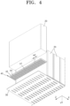
- FIG. 4 is an exploded perspective view of a main component of a cooling structure of a battery pack shown in FIG. 3 .
- FIG. 5 is a view seen from a third direction Z shown in FIG. 3 .
- FIG. 6 is an enlarged view of a thermal-conductive block region of FIG. 5 .
- FIG. 7 is a view seen from a first direction X shown in FIG. 3 .
- a battery pack equipped with a heat non-diffusion cooling structure using a comb shape includes a plurality of battery cells 20, a heat sink 30, and a thermal-conductive block 40.
- the plurality of battery cells 20 may be arranged inside a housing at intervals in the first direction X.
- the plurality of battery cells 20 may form one battery module.
- the heat sink 30 faces the battery cell 20 in a second direction Y that is different from the first direction X.
- the heat sink 30 may continuously extend in the first direction X along a side of the adjacent battery cells 20.
- the heat sink 30 may be manufactured from a material having excellent thermal conductivity. The heat sink 30 may quickly transfer heat occurring in the battery cell 20 to outside to dissipate the heat.
- the thermal-conductive block 40 is between the heat sink 30 and the battery cells 20.
- the thermal-conductive block 40 includes (i.e. each include) a base plate 42 and a fin 44.
- the base plate 42 may be divided or separate for each battery cell 20 in the first direction X.
- one base plate 42 may be for or correspond with one battery cell 20.
- the fin 44 may be a structure that is between the base plate 42 and the heat sink 30.
- the fin 44 may include a cantilever structure extending from the base plate 42.
- a plurality of fins 44 may be provided.
- a first cavity 46 may be between the fins 44.
- the fins 44 and the first cavities 46 may be alternately arranged in the first direction X.
- the fins 44 may be adjacent to each other in the first direction X with the first cavity 46 therebetween.
- the fins 44 may be adjacent to each other in a third direction Z (that is different from the first direction X and the second direction Y) with a second cavity 47 therebetween.
- the fins 44 may be arranged in the first direction X and the third direction Z such that a width w1 of the first cavity 46 in the first direction X is less than a width w2 of the second cavity 47 in the third direction Z.
- a third cavity 48 may be between the fins 44 closest to each other between the thermal-conductive blocks 40 adjacent to each other in the first direction X (e.g., the third cavity may be between outer, facing fins 44 of thermal-conductive blocks 40 corresponding with battery cells 20 that are adjacent in the first direction X).
- the third cavity 48 may be formed across or between the base plates 42 that are adjacent to each other in the first direction X.
- the third cavity 48 may be formed at the same level in an extending direction of the first cavity 46 and the second cavity 47 formed between the same base plates 42 in the first direction X.
- the third cavity 48 may be at the same level as the first cavity 46 and the second cavity 47.
- the third cavity 48 may be between the base plates 42 (and fins 44) that are adjacent to each other in the first direction X, and may be across (e.g., surround a bottom surface of) an insulating sheet 50 between the adjacent base plates 42.
- a width w3 of the third cavity 48 in the first direction X may be greater than the width w1 of the first cavity 46 in the first direction X.
- the insulating sheet 50 may be between the battery cells 20 that are adjacent to each other in the first direction X.
- the insulating sheet 50 may extend between (at least a part of) the thermal-conductive blocks 40 that are adjacent to each other in the first direction X.
- the insulating sheet 50 may extend (in the second direction Y) from between the adjacent battery cells 20 to between the adjacent thermal-conductive blocks 40.
- an extending end (e.g., bottom end) of the insulating sheet 50 may be in the third cavity 48 between the outer, facing fins 44 of the thermal-conductive blocks 40 that are adjacent to each other in the first direction X.
- the insulating sheet 50 may have a first thickness t1 (in the first direction X) at a portion between the adjacent battery cells 20.
- the insulating sheet 50 may have a second thickness t2 (in the first direction X) at a portion between the base plates 42 of adjacent thermal-conductive blocks 40
- the second thickness t2 may be less than the first thickness.
- the insulating sheet 50 may be compressed to form or provide the second thickness t2 that is less than the first thickness t1 between the base plates 42 of the adjacent thermal-conductive blocks 40.
- the insulating sheet 50 may surround or cover corners of facing ends of the adjacent base plates 42.
- the insulating sheet may cover side surfaces of the base plates 42 of the thermal-conductive blocks 40 and top and bottom surfaces adjacent to the side surfaces.
- heat may occur or be generated in the battery cell 20 as charging and discharging are repeated in the battery cell 20.
- the heat in the battery cell 20 may be transferred to the base plate 42 of the thermal-conductive block 40.
- the heat transferred to the base plate 42 may be transferred to the heat sink 30 in the second direction Y through the plurality of fins 44.
- the heat transferred to the heat sink 30 may be quickly conducted in the second direction Y and dissipated to outside. In this process, the heat transferred to the heat sink 30 should be prevented from being transferred to another adjacent battery cell 20 through the adjacent thermal-conductive block 40.
- thermal-conductive block 40 Due to a structure of the thermal-conductive block 40, heat transfer from the base plate 42 to the fin 44 may be easily achieved, and heat transfer from the fin 44 to the base plate 42 may not be easily achieved. This may be because the heat may be cooled or dissipated by the air due to the presence of the first cavity 46, the second cavity 47, and the third cavity 48 between the fins 44.
- the thermal-conductive blocks 40 corresponding to each battery cell 20 may be spaced apart from each other, e.g., without being connected, thereby preventing heat conduction between the adjacent thermal-conductive blocks 40.
- the insulating sheet 50 may be between the adjacent battery cells 20, thereby effectively blocking heat transfer between the battery cells 20 (and between adjacent thermalconducive blocks 40).
- heat transfer from the battery cell 20 to the heat sink 30 may be easily and quickly performed, and heat transfer from the heat sink 30 to the battery cell 20 may be reduced or prevented.
- heat transfer to the adjacent battery cell 20 may be effectively blocked, and the heat may be quickly dissipated to outside through the heat sink 30, thereby greatly improving cooling efficiency of the battery pack.
- the first cavity and the fin of the thermal-conductive block may face the battery cells in the second direction that is different from the first direction, and heat transfer through the thermal-conductive block between the adjacent battery cells may be blocked, thereby improving cooling performance.
- a battery pack may include a plurality of battery modules, and a lot of heat could be generated during repetitive charging and discharging processes in battery cells densely arranged in a small space.
- a battery pack may have a structure for effectively dissipating and cooling heat occurring or generated in the battery cell accommodated therein.
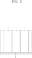
- heat generated in a battery cell 1 may be emitted to the outside by installing a cooling plate 2 under the battery cell 1 as shown in FIGS. 1 and 2 .
- the heat generated in the battery cell 1 may be transferred to the cooling plate 2, and the heat is also transferred to the adjacent battery cell 1, which could damage the adjacent battery cell 1.
- abnormal heat emission such as thermal runaway
- the cooling plate 2 heated to high temperature could transfer the heat to the adjacent battery cell 1, which could damage the adjacent battery cell 1.
- Such an issue could occur a structure in which heat transfer between the battery cell 1 and the cooling plate 2 is bidirectional.
- thermo-conductive block that connects the plurality of battery cells arranged in the first direction to the heat sink to face the battery cells in the second direction
- heat transfer through the thermal-conductive block between the adjacent battery cells may be blocked, thereby improving cooling performance
- One or more embodiments may provide a battery pack having improved cooling performance by effectively blocking heat transfer between battery cells.
- One or more embodiments may provide a battery pack having improved cooling performance by preventing heat transferred from a battery cell to a heat sink from also being transferred to an adjacent battery cell by way of an improved cooling structure of the battery pack.
Landscapes
- Engineering & Computer Science (AREA)
- General Chemical & Material Sciences (AREA)
- Electrochemistry (AREA)
- Chemical Kinetics & Catalysis (AREA)
- Chemical & Material Sciences (AREA)
- Manufacturing & Machinery (AREA)
- Sustainable Energy (AREA)
- Mechanical Engineering (AREA)
- Transportation (AREA)
- Power Engineering (AREA)
- Life Sciences & Earth Sciences (AREA)
- Sustainable Development (AREA)
- Battery Mounting, Suspending (AREA)
- Secondary Cells (AREA)
Abstract
A battery pack equipped with a heat non-diffusion cooling structure having a comb shape, the battery pack includes a plurality of battery cells arranged in a first direction; a heat sink facing the plurality of battery cells in a second direction that is different from the first direction, the heat sink continuously extending along the plurality of battery cells; and thermal-conductive blocks between the heat sink and the plurality of battery cells, wherein the thermal-conductive blocks each include a base plate on one battery cell of the battery cells, and a first cavity and at least one fin alternately arranged in the first direction, the first cavity and the at least one fin being between the base plate and the heat sink.
Description
- Embodiments relate to a battery pack equipped with a heat non-diffusion cooling structure using a comb shape.
- Recently, the production and use of vehicles using electric energy or hybrid vehicles have increased significantly. Electric vehicles or hybrid vehicles are equipped with battery packs. A battery pack may include a plurality of battery modules, each of which includes a plurality of battery cells. Each battery cell may include a cathode, an anode, a separator, an active material, an electrolyte, and the like, and may be repeatedly chargeable and dischargeable through electrochemical reactions.
- The embodiments may be realized by providing a battery pack equipped with a heat non-diffusion cooling structure having a comb shape, the battery pack including a plurality of battery cells arranged in a first direction; a heat sink facing the plurality of battery cells in a second direction that is different from the first direction, the heat sink continuously extending along the plurality of battery cells; and thermal-conductive blocks between the heat sink and the plurality of battery cells, wherein the thermal-conductive blocks each include a base plate on one battery cell of the plurality of battery cells, and a first cavity and at least one fin alternately arranged in the first direction, the first cavity and the at least one fin being between the base plate and the heat sink.
- The at least one fin may include a plurality of fins adjacent to each other in the first direction with the first cavity therebetween, and the plurality of fins may be adjacent to each other in a third direction with a second cavity therebetween, the third direction being different from the first direction and the second direction.
- The plurality of fins may be arranged in the first direction and the third direction such that a width of the first cavity in the first direction is less than a width of the second cavity in the third direction.
- The battery pack may further include a third cavity between facing, outer fins of thermal-conductive blocks that are adjacent to each other in the first direction.
- The third cavity may be between adjacent base plates in the first direction and is at a same level as the first cavity and the second cavity.
- The battery pack may further include an insulating sheet between adjacent base plates, wherein the third cavity is between adjacent base plates adjacent in the first direction and on the insulating sheet between adjacent base plates, and a width of the third cavity in the first direction is greater than a width of the first cavity in the first direction.
- The insulating sheet may be further between the plurality of battery cells that are adjacent to each other in the first direction, and the insulating sheet may extend at least partially between the thermal-conductive blocks that are adjacent to each other in the first direction.
- The insulating sheet may extend in the second direction from between adjacent ones of the plurality of battery cells to between adjacent thermal-conductive blocks, and an extending end of the insulating sheet may be in the third cavity between outer, facing fins of thermal-conductive blocks that are adjacent to each other in the first direction.
- The insulating sheet may have a first thickness in the first direction between the plurality of battery cells that are adjacent to each other, and the insulating sheet may have a second thickness in the first direction between the base plates of the thermal-conductive blocks that are adjacent to each other, the second thickness being different from the first thickness.
- The second thickness may be less than the first thickness.
- The insulating sheet may surround corners of facing side surfaces of the base plates of the thermal-conductive blocks that are adjacent to each other, and portions of top and bottom surfaces of the base plates adjacent to the side surfaces.
- At least some of the above and other features of the invention are set out in the claims.
- Features will be apparent to those of skill in the art by describing in detail embodiments with reference to the attached drawings in which:
-
FIG. 1 shows an example of a cooling structure of a comparative battery pack; -
FIG. 2 is a side view of a battery pack shown inFIG. 1 ; -
FIG. 3 shows a cooling structure of a battery pack according to the present disclosure; -
FIG. 4 is an exploded perspective view of a main component of a cooling structure of a battery pack shown inFIG. 3 ; -
FIG. 5 is a view seen from a third direction Z shown inFIG. 3 ; -
FIG. 6 is an enlarged view of a thermal-conductive block region ofFIG. 5 ; and -
FIG. 7 is a view seen from a first direction X shown inFIG. 3 . - Example embodiments will now be described more fully hereinafter with reference to the accompanying drawings; however, they may be embodied in different forms and should not be construed as limited to the embodiments set forth herein. Rather, these embodiments are provided so that this disclosure will be thorough and complete, and will fully convey implementations to those skilled in the art.
- In the drawing figures, the dimensions of layers and regions may be exaggerated for clarity of illustration. It will also be understood that when a layer or element is referred to as being "on" another layer or element, it can be directly on the other layer or element, or intervening layers may also be present. Further, it will be understood that when a layer is referred to as being "under" another layer, it can be directly under, and one or more intervening layers may also be present. In addition, it will also be understood that when a layer is referred to as being "between" two layers, it can be the only layer between the two layers, or one or more intervening layers may also be present. Like reference numerals refer to like elements throughout.
- When a portion is referred to as "including" a component, the portion may not exclude another component but may further include another component unless stated otherwise. More specifically, it should be understood that the term "include", "have", or the like used herein is to indicate the presence of features, numbers, steps, operations, components, parts, or a combination thereof described in the specifications, and does not preclude the presence or addition of one or more other features, numbers, steps, operations, components, parts, or a combination thereof.
- Singular forms include plural forms unless apparently indicated otherwise contextually.
-
FIG. 3 shows a cooling structure of a battery pack according to the present disclosure.FIG. 4 is an exploded perspective view of a main component of a cooling structure of a battery pack shown inFIG. 3 .FIG. 5 is a view seen from a third direction Z shown inFIG. 3 .FIG. 6 is an enlarged view of a thermal-conductive block region ofFIG. 5 .FIG. 7 is a view seen from a first direction X shown inFIG. 3 . - Referring to
FIGS. 3 to 7 , a battery pack equipped with a heat non-diffusion cooling structure using a comb shape according to embodiments of the present disclosure (hereinafter, referred to as a "battery pack") includes a plurality ofbattery cells 20, aheat sink 30, and a thermal-conductive block 40. - The plurality of
battery cells 20 may be arranged inside a housing at intervals in the first direction X. The plurality ofbattery cells 20 may form one battery module. - The
heat sink 30 faces thebattery cell 20 in a second direction Y that is different from the first direction X. Theheat sink 30 may continuously extend in the first direction X along a side of theadjacent battery cells 20. Theheat sink 30 may be manufactured from a material having excellent thermal conductivity. Theheat sink 30 may quickly transfer heat occurring in thebattery cell 20 to outside to dissipate the heat. - The thermal-
conductive block 40 is between theheat sink 30 and thebattery cells 20. The thermal-conductive block 40 includes (i.e. each include) abase plate 42 and afin 44. - The
base plate 42 may be divided or separate for eachbattery cell 20 in the first direction X. In an implementation, onebase plate 42 may be for or correspond with onebattery cell 20. Thefin 44 may be a structure that is between thebase plate 42 and theheat sink 30. Thefin 44 may include a cantilever structure extending from thebase plate 42. In an implementation, a plurality offins 44 may be provided. Afirst cavity 46 may be between thefins 44. Thefins 44 and thefirst cavities 46 may be alternately arranged in the first direction X. - The
fins 44 may be adjacent to each other in the first direction X with thefirst cavity 46 therebetween. Thefins 44 may be adjacent to each other in a third direction Z (that is different from the first direction X and the second direction Y) with asecond cavity 47 therebetween. - The
fins 44 may be arranged in the first direction X and the third direction Z such that a width w1 of thefirst cavity 46 in the first direction X is less than a width w2 of thesecond cavity 47 in the third direction Z. - A third cavity 48 may be between the
fins 44 closest to each other between the thermal-conductive blocks 40 adjacent to each other in the first direction X (e.g., the third cavity may be between outer, facingfins 44 of thermal-conductive blocks 40 corresponding withbattery cells 20 that are adjacent in the first direction X). - The third cavity 48 may be formed across or between the
base plates 42 that are adjacent to each other in the first direction X. The third cavity 48 may be formed at the same level in an extending direction of thefirst cavity 46 and thesecond cavity 47 formed between thesame base plates 42 in the first direction X. In an implementation, the third cavity 48 may be at the same level as thefirst cavity 46 and thesecond cavity 47. - The third cavity 48 may be between the base plates 42 (and fins 44) that are adjacent to each other in the first direction X, and may be across (e.g., surround a bottom surface of) an insulating
sheet 50 between theadjacent base plates 42. A width w3 of the third cavity 48 in the first direction X may be greater than the width w1 of thefirst cavity 46 in the first direction X. - The insulating
sheet 50 may be between thebattery cells 20 that are adjacent to each other in the first direction X. The insulatingsheet 50 may extend between (at least a part of) the thermal-conductive blocks 40 that are adjacent to each other in the first direction X. - The insulating
sheet 50 may extend (in the second direction Y) from between theadjacent battery cells 20 to between the adjacent thermal-conductive blocks 40. In an implementation, an extending end (e.g., bottom end) of the insulatingsheet 50 may be in the third cavity 48 between the outer, facingfins 44 of the thermal-conductive blocks 40 that are adjacent to each other in the first direction X. - The insulating
sheet 50 may have a first thickness t1 (in the first direction X) at a portion between theadjacent battery cells 20. The insulatingsheet 50 may have a second thickness t2 (in the first direction X) at a portion between thebase plates 42 of adjacent thermal-conductive blocks 40 In an implementation, the second thickness t2 may be less than the first thickness. In an implementation, the insulatingsheet 50 may be compressed to form or provide the second thickness t2 that is less than the first thickness t1 between thebase plates 42 of the adjacent thermal-conductive blocks 40. - The insulating
sheet 50 may surround or cover corners of facing ends of theadjacent base plates 42. In an implementation, the insulating sheet may cover side surfaces of thebase plates 42 of the thermal-conductive blocks 40 and top and bottom surfaces adjacent to the side surfaces. - Hereinbelow, the working effect of the present disclosure will be described in detail along a heat transfer path in a battery pack including the above-described components.
- Referring to
FIG. 6 , heat may occur or be generated in thebattery cell 20 as charging and discharging are repeated in thebattery cell 20. The heat in thebattery cell 20 may be transferred to thebase plate 42 of the thermal-conductive block 40. The heat transferred to thebase plate 42 may be transferred to theheat sink 30 in the second direction Y through the plurality offins 44. The heat transferred to theheat sink 30 may be quickly conducted in the second direction Y and dissipated to outside. In this process, the heat transferred to theheat sink 30 should be prevented from being transferred to anotheradjacent battery cell 20 through the adjacent thermal-conductive block 40. Due to a structure of the thermal-conductive block 40, heat transfer from thebase plate 42 to thefin 44 may be easily achieved, and heat transfer from thefin 44 to thebase plate 42 may not be easily achieved. This may be because the heat may be cooled or dissipated by the air due to the presence of thefirst cavity 46, thesecond cavity 47, and the third cavity 48 between thefins 44. The thermal-conductive blocks 40 corresponding to eachbattery cell 20 may be spaced apart from each other, e.g., without being connected, thereby preventing heat conduction between the adjacent thermal-conductive blocks 40. The insulatingsheet 50 may be between theadjacent battery cells 20, thereby effectively blocking heat transfer between the battery cells 20 (and between adjacent thermalconducive blocks 40). Thus, heat transfer from thebattery cell 20 to theheat sink 30 may be easily and quickly performed, and heat transfer from theheat sink 30 to thebattery cell 20 may be reduced or prevented. As a result, even if any one of theadjacent battery cells 20 were to be overheated, heat transfer to theadjacent battery cell 20 may be effectively blocked, and the heat may be quickly dissipated to outside through theheat sink 30, thereby greatly improving cooling efficiency of the battery pack. - As described above, according to the present disclosure, the first cavity and the fin of the thermal-conductive block (that is between the plurality of battery cells and the heat sink) may face the battery cells in the second direction that is different from the first direction, and heat transfer through the thermal-conductive block between the adjacent battery cells may be blocked, thereby improving cooling performance.
- By way of summation and review, a battery pack may include a plurality of battery modules, and a lot of heat could be generated during repetitive charging and discharging processes in battery cells densely arranged in a small space. A battery pack may have a structure for effectively dissipating and cooling heat occurring or generated in the battery cell accommodated therein.
- In one way to lower a temperature that increased due to heat generated in a battery cell inside a battery pack, heat generated in a
battery cell 1 may be emitted to the outside by installing a cooling plate 2 under thebattery cell 1 as shown inFIGS. 1 and2 . In this process, the heat generated in thebattery cell 1 may be transferred to the cooling plate 2, and the heat is also transferred to theadjacent battery cell 1, which could damage theadjacent battery cell 1. If abnormal heat emission (such as thermal runaway) were to occur in onebattery cell 1, the cooling plate 2 heated to high temperature could transfer the heat to theadjacent battery cell 1, which could damage theadjacent battery cell 1. Such an issue could occur a structure in which heat transfer between thebattery cell 1 and the cooling plate 2 is bidirectional. - According to the present disclosure, due to the first cavity and the fin portion in the thermal-conductive block that connects the plurality of battery cells arranged in the first direction to the heat sink to face the battery cells in the second direction, heat transfer through the thermal-conductive block between the adjacent battery cells may be blocked, thereby improving cooling performance.
- One or more embodiments may provide a battery pack having improved cooling performance by effectively blocking heat transfer between battery cells.
- One or more embodiments may provide a battery pack having improved cooling performance by preventing heat transferred from a battery cell to a heat sink from also being transferred to an adjacent battery cell by way of an improved cooling structure of the battery pack.
- Example embodiments have been disclosed herein, and although specific terms are employed, they are used and are to be interpreted in a generic and descriptive sense only and not for purposes of limitation. In some instances, as would be apparent to one of ordinary skill in the art as of the filing of the present application, features, characteristics, and/or elements described in connection with a particular embodiment may be used singly or in combination with features, characteristics, and/or elements described in connection with other embodiments unless otherwise specifically indicated. Accordingly, it will be understood by those of skill in the art that various changes in form and details may be made without departing from the scope of the present invention as set forth in the following claims.
Claims (11)
- A battery pack equipped with a heat non-diffusion cooling structure having a comb shape, the battery pack comprising:a plurality of battery cells arranged in a first direction;a heat sink facing the plurality of battery cells in a second direction that is different from the first direction, the heat sink continuously extending along the plurality of battery cells; andthermal-conductive blocks between the heat sink and the plurality of battery cells,wherein the thermal-conductive blocks each include:a base plate on one battery cell of the plurality of battery cells, anda first cavity and at least one fin alternately arranged in the first direction, the first cavity and the at least one fin being between the base plate and the heat sink.
- The battery pack as claimed in claim 1, wherein:the at least one fin includes a plurality of fins adjacent to each other in the first direction with the first cavity therebetween, andthe plurality of fins are adjacent to each other in a third direction with a second cavity therebetween, the third direction being different from the first direction and the second direction.
- The battery pack as claimed in claim 2, wherein the plurality of fins are arranged in the first direction and the third direction such that a width of the first cavity in the first direction is less than a width of the second cavity in the third direction.
- The battery pack as claimed in claim 3, further comprising a third cavity between facing, outer fins of thermal-conductive blocks that are adjacent to each other in the first direction.
- The battery pack as claimed in claim 4, wherein the third cavity is between adjacent base plates in the first direction and is at a same level as the first cavity and the second cavity.
- The battery pack as claimed in claim 4, further comprising an insulating sheet between adjacent base plates,
wherein:the third cavity is between adjacent base plates adjacent in the first direction and on the insulating sheet between adjacent base plates, anda width of the third cavity in the first direction is greater than a width of the first cavity in the first direction. - The battery pack as claimed in claim 6, wherein:the insulating sheet is further between the plurality of battery cells that are adjacent to each other in the first direction, andthe insulating sheet extends at least partially between the thermal-conductive blocks that are adjacent to each other in the first direction.
- The battery pack as claimed in claim 7, wherein:the insulating sheet extends in the second direction from between adjacent ones of the plurality of battery cells to between adj acent thermal-conductive blocks, andan extending end of the insulating sheet is in the third cavity between outer, facing fins of thermal-conductive blocks that are adjacent to each other in the first direction.
- The battery pack as claimed in claim 7 or claim 8, wherein:the insulating sheet has a first thickness in the first direction between the plurality of battery cells that are adjacent to each other, andthe insulating sheet has a second thickness in the first direction between the base plates of the thermal-conductive blocks that are adjacent to each other, the second thickness being different from the first thickness.
- The battery pack as claimed in claim 9, wherein the second thickness is less than the first thickness.
- The battery pack as claimed in any one of claims 7 to 10, wherein the insulating sheet surrounds corners of facing side surfaces of the base plates of the thermal-conductive blocks that are adjacent to each other, and portions of top and bottom surfaces of the base plates adjacent to the side surfaces.
Applications Claiming Priority (2)
| Application Number | Priority Date | Filing Date | Title |
|---|---|---|---|
| KR20230039350 | 2023-03-26 | ||
| KR1020230095482A KR20240144835A (en) | 2023-03-26 | 2023-07-21 | Battery pack equipped with heat non-diffusion cooling structure using comb shape |
Publications (1)
| Publication Number | Publication Date |
|---|---|
| EP4443607A1 true EP4443607A1 (en) | 2024-10-09 |
Family
ID=90366344
Family Applications (1)
| Application Number | Title | Priority Date | Filing Date |
|---|---|---|---|
| EP24163988.9A Pending EP4443607A1 (en) | 2023-03-26 | 2024-03-15 | Battery pack equipped with heat non-diffusion cooling structure using comb shape |
Country Status (5)
| Country | Link |
|---|---|
| US (1) | US20240322288A1 (en) |
| EP (1) | EP4443607A1 (en) |
| KR (1) | KR20250150021A (en) |
| CN (1) | CN222214266U (en) |
| WO (1) | WO2024205152A1 (en) |
Citations (3)
| Publication number | Priority date | Publication date | Assignee | Title |
|---|---|---|---|---|
| CN106935751A (en) * | 2015-11-05 | 2017-07-07 | 福特全球技术公司 | Traction battery support component |
| US20200406784A1 (en) * | 2018-01-30 | 2020-12-31 | Sanyo Electric Co., Ltd. | Power source device and electric vehicle equipped with power source device |
| US20210273278A1 (en) * | 2018-07-09 | 2021-09-02 | Sanyo Electric Co., Ltd. | Battery system, electric vehicle equipped with battery system, and electricity storage device |
Family Cites Families (5)
| Publication number | Priority date | Publication date | Assignee | Title |
|---|---|---|---|---|
| JP2009301877A (en) * | 2008-06-13 | 2009-12-24 | Toyoda Gosei Co Ltd | Battery pack device |
| KR20110118807A (en) * | 2010-01-29 | 2011-11-01 | 파나소닉 주식회사 | Battery module |
| JP2012243619A (en) * | 2011-05-20 | 2012-12-10 | Kobelco Contstruction Machinery Ltd | Capacitor |
| KR102258174B1 (en) * | 2017-04-26 | 2021-05-28 | 주식회사 엘지에너지솔루션 | Battery module, battery pack comprising the battery module and vehicle comprising the battery pack |
| JP7116653B2 (en) * | 2018-09-20 | 2022-08-10 | 信越ポリマー株式会社 | Heat dissipation structure and battery with same |
-
2023
- 2023-10-23 US US18/382,704 patent/US20240322288A1/en active Pending
-
2024
- 2024-03-15 EP EP24163988.9A patent/EP4443607A1/en active Pending
- 2024-03-22 KR KR1020257029775A patent/KR20250150021A/en active Pending
- 2024-03-22 WO PCT/KR2024/003659 patent/WO2024205152A1/en not_active Ceased
- 2024-03-25 CN CN202420582492.9U patent/CN222214266U/en active Active
Patent Citations (3)
| Publication number | Priority date | Publication date | Assignee | Title |
|---|---|---|---|---|
| CN106935751A (en) * | 2015-11-05 | 2017-07-07 | 福特全球技术公司 | Traction battery support component |
| US20200406784A1 (en) * | 2018-01-30 | 2020-12-31 | Sanyo Electric Co., Ltd. | Power source device and electric vehicle equipped with power source device |
| US20210273278A1 (en) * | 2018-07-09 | 2021-09-02 | Sanyo Electric Co., Ltd. | Battery system, electric vehicle equipped with battery system, and electricity storage device |
Also Published As
| Publication number | Publication date |
|---|---|
| KR20250150021A (en) | 2025-10-17 |
| WO2024205152A1 (en) | 2024-10-03 |
| US20240322288A1 (en) | 2024-09-26 |
| CN222214266U (en) | 2024-12-20 |
Similar Documents
| Publication | Publication Date | Title |
|---|---|---|
| US10446891B2 (en) | Submodule and battery module having the same | |
| EP3154103B1 (en) | Battery module including a housing floor with integrated cooling | |
| JP5540070B2 (en) | Battery module and battery pack | |
| US10020549B2 (en) | Battery module with novel structure | |
| US9865904B2 (en) | Battery cell of improved cooling efficiency | |
| EP3163673B1 (en) | Battery cell cooling device and battery module including same | |
| CN102484300B (en) | Battery module with temperature sensor mounted thereon and medium-to-large battery pack including the battery module | |
| US8323819B2 (en) | Battery module of improved cooling efficiency | |
| US20060214641A1 (en) | Rechargeable battery module | |
| JP2004362879A (en) | Collective battery | |
| CN111081926B (en) | Battery module | |
| JP2023527334A (en) | Battery modules and battery packs containing the same | |
| EP4443607A1 (en) | Battery pack equipped with heat non-diffusion cooling structure using comb shape | |
| US12015134B2 (en) | Battery unit having cell stack, bus bars, cooler, waterproof plate, and heat transfer member | |
| US12537242B2 (en) | Battery module with improved uniformity in temperature of battery cells | |
| CN118712599A (en) | Battery pack equipped with comb-shaped heat diffusion-free cooling structure | |
| KR100684758B1 (en) | Secondary battery module | |
| KR20240144835A (en) | Battery pack equipped with heat non-diffusion cooling structure using comb shape | |
| KR102260389B1 (en) | Secondary Battery Cell having Improved Cooling Performance and Secondary Battery module having plurality of the Secondary Battery Cells | |
| KR20240102500A (en) | Battery Pack Having Improved Cooling Performance | |
| KR20240146884A (en) | Battery pack | |
| KR20240174679A (en) | Battery module and battery pack comprising the same | |
| KR20250157894A (en) | Battery cell assembly and battery pack including the same | |
| KR20250170365A (en) | Battery cell assembly and battery pack including the same | |
| KR20260032228A (en) | Battery pack |
Legal Events
| Date | Code | Title | Description |
|---|---|---|---|
| PUAI | Public reference made under article 153(3) epc to a published international application that has entered the european phase |
Free format text: ORIGINAL CODE: 0009012 |
|
| STAA | Information on the status of an ep patent application or granted ep patent |
Free format text: STATUS: REQUEST FOR EXAMINATION WAS MADE |
|
| 17P | Request for examination filed |
Effective date: 20240315 |
|
| AK | Designated contracting states |
Kind code of ref document: A1 Designated state(s): AL AT BE BG CH CY CZ DE DK EE ES FI FR GB GR HR HU IE IS IT LI LT LU LV MC ME MK MT NL NO PL PT RO RS SE SI SK SM TR |