EP4443606A2 - Strukturkorb zur aufnahme von batteriemodulen mit gestapelten elektrochemischen elementen, batterie und montageverfahren dafür - Google Patents
Strukturkorb zur aufnahme von batteriemodulen mit gestapelten elektrochemischen elementen, batterie und montageverfahren dafür Download PDFInfo
- Publication number
- EP4443606A2 EP4443606A2 EP24163750.3A EP24163750A EP4443606A2 EP 4443606 A2 EP4443606 A2 EP 4443606A2 EP 24163750 A EP24163750 A EP 24163750A EP 4443606 A2 EP4443606 A2 EP 4443606A2
- Authority
- EP
- European Patent Office
- Prior art keywords
- stiffener
- transverse
- fixing member
- module
- basket
- Prior art date
- Legal status (The legal status is an assumption and is not a legal conclusion. Google has not performed a legal analysis and makes no representation as to the accuracy of the status listed.)
- Pending
Links
Images



Classifications
-
- H—ELECTRICITY
- H01—ELECTRIC ELEMENTS
- H01M—PROCESSES OR MEANS, e.g. BATTERIES, FOR THE DIRECT CONVERSION OF CHEMICAL ENERGY INTO ELECTRICAL ENERGY
- H01M50/00—Constructional details or processes of manufacture of the non-active parts of electrochemical cells other than fuel cells, e.g. hybrid cells
- H01M50/20—Mountings; Secondary casings or frames; Racks, modules or packs; Suspension devices; Shock absorbers; Transport or carrying devices; Holders
- H01M50/204—Racks, modules or packs for multiple batteries or multiple cells
-
- H—ELECTRICITY
- H01—ELECTRIC ELEMENTS
- H01M—PROCESSES OR MEANS, e.g. BATTERIES, FOR THE DIRECT CONVERSION OF CHEMICAL ENERGY INTO ELECTRICAL ENERGY
- H01M10/00—Secondary cells; Manufacture thereof
- H01M10/60—Heating or cooling; Temperature control
- H01M10/61—Types of temperature control
- H01M10/613—Cooling or keeping cold
-
- H—ELECTRICITY
- H01—ELECTRIC ELEMENTS
- H01M—PROCESSES OR MEANS, e.g. BATTERIES, FOR THE DIRECT CONVERSION OF CHEMICAL ENERGY INTO ELECTRICAL ENERGY
- H01M10/00—Secondary cells; Manufacture thereof
- H01M10/60—Heating or cooling; Temperature control
- H01M10/62—Heating or cooling; Temperature control specially adapted for specific applications
- H01M10/625—Vehicles
-
- H—ELECTRICITY
- H01—ELECTRIC ELEMENTS
- H01M—PROCESSES OR MEANS, e.g. BATTERIES, FOR THE DIRECT CONVERSION OF CHEMICAL ENERGY INTO ELECTRICAL ENERGY
- H01M10/00—Secondary cells; Manufacture thereof
- H01M10/60—Heating or cooling; Temperature control
- H01M10/65—Means for temperature control structurally associated with the cells
- H01M10/655—Solid structures for heat exchange or heat conduction
- H01M10/6554—Rods or plates
-
- H—ELECTRICITY
- H01—ELECTRIC ELEMENTS
- H01M—PROCESSES OR MEANS, e.g. BATTERIES, FOR THE DIRECT CONVERSION OF CHEMICAL ENERGY INTO ELECTRICAL ENERGY
- H01M10/00—Secondary cells; Manufacture thereof
- H01M10/60—Heating or cooling; Temperature control
- H01M10/65—Means for temperature control structurally associated with the cells
- H01M10/655—Solid structures for heat exchange or heat conduction
- H01M10/6556—Solid parts with flow channel passages or pipes for heat exchange
-
- H—ELECTRICITY
- H01—ELECTRIC ELEMENTS
- H01M—PROCESSES OR MEANS, e.g. BATTERIES, FOR THE DIRECT CONVERSION OF CHEMICAL ENERGY INTO ELECTRICAL ENERGY
- H01M50/00—Constructional details or processes of manufacture of the non-active parts of electrochemical cells other than fuel cells, e.g. hybrid cells
- H01M50/20—Mountings; Secondary casings or frames; Racks, modules or packs; Suspension devices; Shock absorbers; Transport or carrying devices; Holders
- H01M50/244—Secondary casings; Racks; Suspension devices; Carrying devices; Holders characterised by their mounting method
-
- H—ELECTRICITY
- H01—ELECTRIC ELEMENTS
- H01M—PROCESSES OR MEANS, e.g. BATTERIES, FOR THE DIRECT CONVERSION OF CHEMICAL ENERGY INTO ELECTRICAL ENERGY
- H01M50/00—Constructional details or processes of manufacture of the non-active parts of electrochemical cells other than fuel cells, e.g. hybrid cells
- H01M50/20—Mountings; Secondary casings or frames; Racks, modules or packs; Suspension devices; Shock absorbers; Transport or carrying devices; Holders
- H01M50/249—Mountings; Secondary casings or frames; Racks, modules or packs; Suspension devices; Shock absorbers; Transport or carrying devices; Holders specially adapted for aircraft or vehicles, e.g. cars or trains
-
- H—ELECTRICITY
- H01—ELECTRIC ELEMENTS
- H01M—PROCESSES OR MEANS, e.g. BATTERIES, FOR THE DIRECT CONVERSION OF CHEMICAL ENERGY INTO ELECTRICAL ENERGY
- H01M50/00—Constructional details or processes of manufacture of the non-active parts of electrochemical cells other than fuel cells, e.g. hybrid cells
- H01M50/20—Mountings; Secondary casings or frames; Racks, modules or packs; Suspension devices; Shock absorbers; Transport or carrying devices; Holders
- H01M50/262—Mountings; Secondary casings or frames; Racks, modules or packs; Suspension devices; Shock absorbers; Transport or carrying devices; Holders with fastening means, e.g. locks
- H01M50/264—Mountings; Secondary casings or frames; Racks, modules or packs; Suspension devices; Shock absorbers; Transport or carrying devices; Holders with fastening means, e.g. locks for cells or batteries, e.g. straps, tie rods or peripheral frames
Definitions
- Such a structural basket when it receives battery modules (designated by the English term "cell block"), is intended in particular to form a mechanically robust battery, while having a high density of electrochemical elements, in particular for applications in the field of transport, in particular in the automobile, rail transport, or even air transport.
- cell block battery modules
- the battery modules When a battery is used in the transport sector, the battery modules must be arranged in structural baskets to ensure their integrity during transport, and to provide mechanical resistance in the event of significant deceleration.
- Such baskets typically feature a structure with end walls, and stiffeners providing mechanical longitudinal strength between the walls.
- Structural baskets offer high mechanical strength, but do not provide adequate support for electrochemical element modules given the manufacturing tolerances between, on the one hand, the rigid, non-deformable structure formed by the stiffeners and the walls and, on the other hand, the stack of electrochemical elements which is more or less compressed.
- Such a chassis present in each module is therefore effective in guaranteeing mechanical integrity to the module, but has the disadvantage of being bulky.
- the density of electrochemical elements received in the structural basket and therefore the total power of the battery is thus limited by the space occupied by the frames.
- An aim of the invention is to provide a structural basket which guarantees great mechanical robustness, in particular for applications in the field of rail transport, while offering a maximized density of elements to have maximum electrical power.
- the invention relates to a structural basket of the aforementioned type, characterized in that at least one stiffener is movable transversely on the bottom over a transverse position adjustment stroke of the stiffener, the structural basket comprising a transverse locking system of the or each movable stiffener, in at least two distinct transverse positions along the adjustment stroke, in particular in any transverse position along the adjustment stroke.
- a first battery 10 according to the invention is illustrated by the Figures 1 to 7 .
- the battery 10 is intended to be mounted in particular in a vehicle, alone or in the form of a stack of batteries 10.
- the vehicles which can receive batteries 10 according to the invention are, for example, land transport vehicles such as motor vehicles or railway vehicles or even naval or air transport vehicles.
- the battery 10 is intended to provide electrical power to equipment of the vehicle, and also to be connected to a source of electrical power to be recharged.
- the battery 10 comprises a structural basket 12 and a plurality of battery modules 14 formed from stacks of electrochemical elements 16, the battery modules 14 being received and mechanically held in the structural basket 12.
- electrochemical element we mean in particular an assembly of electrodes, electrolyte, container, terminals and generally separators, which is a source of electrical energy obtained by direct transformation of chemical energy.
- the electrochemical elements 16 are prismatic elements which each comprise a container 18, with in particular a general shape of a parallelepiped, in particular a rectangular parallelepiped.
- the electrochemical elements 16 are pockets.
- the container 18 or pocket contains electrodes of opposite polarities stacked alternately with the interposition of at least one separator.
- Electrochemical elements are for example rechargeable Lithium-Ion, Ni/Cd, Ni/MH type.
- each electrochemical element 16 has two opposite front surfaces 20 and two opposite side surfaces 22 connecting the front surfaces 20 together.
- the battery module 14 comprises a plurality of electrochemical elements 16 stacked on top of each other successively by their front surfaces 20.
- the two front surfaces 20 of each electrochemical element 16 are each in contact respectively with the front surface 20 of another electrochemical element 16, with the exception of the electrochemical elements 16 at the ends of the battery module 14 which have a free front surface 20.
- the lateral surfaces 22 of the electrochemical elements 16 are generally aligned with respect to each other. They are located substantially in two planes extending parallel to a longitudinal axis AA' of the battery module (see figure 1 ).
- each battery module 14 is devoid of a holding frame.
- each battery module advantageously comprises a connecting strip 24 connecting the electrochemical elements 16 together, the connecting strip 24 being fixed on the lateral surfaces 22 and on the front end surfaces 20 of two of the electrochemical elements 16.
- the connecting strip is for example formed from a plastic ribbon, provided with an adhesive on one face in contact with the side surfaces 22 and with the front surface 20.
- the structural basket 12 receives one or more battery modules 14 arranged in the form of a row extending in a longitudinal module-receiving direction BB'.
- each row of battery modules 14 contains three successive battery modules 14 arranged end to end in a receiving compartment of the structural basket 12.
- the number of battery modules in each row is for example between 1 and 10, especially between 2 and 5.
- each electrochemical element 16 defines electrical connection terminals 26 which can be connected to each other and to connectors external to the battery 10 via a connection (not shown).
- the basket 12 comprises a bottom 30, and end walls 32, mounted transversely on the bottom and delimiting between them an intermediate space 34 for receiving the battery modules 14.
- the basket 12 further comprises a plurality of stiffeners 36 connecting the end walls 32 together.
- at least one stiffener 36 is movable on the bottom 30 transversely relative to the longitudinal direction BB' for receiving the module over a transverse position adjustment stroke of the stiffener 36.
- the basket 12 further comprises a system 38 for axially locking the stiffeners 36 on the end walls 32, and a system 40 for transversely locking the stiffeners 36 in at least two distinct transverse positions along the adjustment stroke, in particular in any transverse position along the adjustment stroke.
- the structural basket 12 further advantageously comprises a system 42 for wedging the modules 14.
- the bottom 30 is a heat exchange plate, for example made of metal, in particular aluminum.
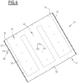
- the heat exchange plate internally defines at least one channel 50 (visible in the figure 6 ), defining a circulation path for a cooling fluid within the plate.
- the or each channel 50 is connected to an inlet fluid connector 52 and an outlet fluid connector 54 respectively for supplying and discharging the cooling fluid into the channel 50.
- the bottom 30 defines an inner face 56 which partly delimits the intermediate space 34 and an opposite outer face 58, visible on the figure 6 , which can constitute a sealing face of another battery 10 when several batteries 10 are stacked on top of each other.
- the end walls 32 project vertically relative to the bottom 30. They extend substantially transversely relative to the longitudinal direction B-B' for receiving the module, along the transverse edges of the bottom 30.
- Each wall 32 is here formed by an openwork profile.
- Each wall 32 thus has a vertical outer face 60, and a vertical inner face 62, opposite and parallel to the outer face 60.
- the inner face 62 partially delimits the intermediate space 34.
- the stiffeners 36 extend parallel to the longitudinal direction B-B' of module reception by connecting the end walls 32.
- Each pair of adjacent stiffeners 36 delimits a compartment for receiving a row of battery modules 14, between the lateral faces 68, 70 of the two stiffeners 36.
- the receiving compartment preferably comprises a single row of battery modules 14 comprising one or more battery modules 14 aligned parallel to the longitudinal direction B-B' for receiving the module.
- Each stiffener 36 comprises a first longitudinal end 64 fixed to the inner face 62 of a first end wall 32, and a second longitudinal end 66 fixed to the inner face 62 of a second end wall 32 located opposite the first end wall 32.
- Each stiffener 36 has a profiled shape defining a height greater than its thickness.
- Each stiffener 36 thus has opposite lateral faces 68, 70, a lower edge 72 applied to the inner face 56 of the bottom 30 and an upper edge 74.
- the upper edge 74 is here advantageously located at a height lower than the height of the upper edge of each end wall 32.
- the upper edge 74 advantageously defines at least one slot 76 for housing the transverse locking system 40, preferably a plurality of slots 76 spaced longitudinally.
- At least one stiffener 36 preferably all the stiffeners 36 except a reference stiffener 36, are mounted to move transversely on the bottom 30 of the basket 12 relative to the longitudinal direction B-B' of module reception, over a stroke for adjusting the transverse position of the stiffener 36.
- each mobile stiffener 36 is formed from a profile having an upper stiffening region 80 and a lower openwork region 82.
- the upper region 80 is solid, with the exception of the slots 76 which it delimits along the stiffener 36. As visible on the figure 4 , it internally defines an orifice 83 for receiving a fixing member of the axial locking system 38, extending parallel to the longitudinal direction B-B'.
- the lower region 82 is integral with the upper region 80. It defines two upper right side partitions 84A, 84B, two lower right side partitions 86A, 86B and a bottom partition 88 connecting the two lower right side partitions 86A, 86B together.
- the lower region 82 also defines a central sleeve 90 for receiving a fixing member of the axial locking system 38 and an openwork crosspiece 92 connecting the central sleeve 90 to the upper lateral partitions 84A, 84B and to the lower lateral partitions 86A, 86B.
- the partitions 86A, 86B and 84A, 84B define a portion of the lateral faces 68, 70 of the stiffener 36.
- the partitions 84A, 86A are preferably located in the same plane, parallel to the plane in which the partitions 84B, 86B are preferably located. They extend vertically, parallel to the longitudinal direction B-B' for receiving the module.
- the partitions 84A, 84B; 86A, 86B respectively delimit between them intermediate spaces 94, 96 devoid of material.
- the central sleeve 90 defines a central orifice 98 for receiving the fixing member of the axial locking system 38 with an axis parallel to the longitudinal direction B-B'.
- central sleeve 90 is cylindrical in shape and has a diameter less than the distance separating the side faces 68, 70 from each other.
- the openwork crosspiece 92 comprises inclined walls 100.
- the inclined walls 100 extend from each of the partitions 84A, 84B, 86A, 86B to connect to the central socket 90.
- the inclined walls 100 and the outer surface of the sleeve 90 define in each lateral face 68, 70 of the stiffener 36, a longitudinal recess 102 which opens laterally towards the outside.
- the recess 102 here extends over the entire length of the stiffener 36, parallel to the longitudinal direction B-B' for receiving the module.
- the lower region 82 has a structurally strong structure while being very light.
- the axial locking system 38 comprises for each stiffener 36, at each end 64, 66, at least one axial fixing member 110 which is here formed by a screw.
- the axial locking system 38 comprises at each end 64, 66 of a stiffener 36, two axial fixing members 110, received respectively in the orifice 83 formed in the upper region 80 and in the orifice 98 delimited in the central sleeve 90.
- the axial locking system 38 further comprises for each stiffener 36, a through cavity 112 formed through the end wall 32.
- the cavity 112 is of horizontally elongated shape (see figure 2 ), perpendicular to the longitudinal direction BB' of module reception.
- the length of the cavity 112 is greater than or equal to the adjustment stroke of the transverse position of the stiffener 36.
- the axial fixing member 110 preferably comprises a rod 114 extending through the through cavity 112 and through the stiffener 36, and a head 116 applying to the outer face 60 of the end wall 32, overlapping the through cavity 112.
- the transverse locking system 40 is configured to transversely lock each movable stiffener 36 in at least two given positions along its transverse travel, preferably in each given position along its transverse travel.
- the transverse locking system 40 comprises at least one transverse fixing member 120 (visible in particular on the figure 3 ), of preferably several transverse fixing members 120 distributed along the stiffener 36, each advantageously being received in a slot 76.
- the transverse locking system 40 comprises, for each transverse fixing member 120, a locking nut 122.
- the transverse locking system 40 further defines, for each transverse fixing member 120, a through orifice 124 for locking the fixing member 120 in rotation relative to the stiffener 36, formed in the bottom partition 88 of the stiffener 36, an oblong hole 126 for inserting the transverse fixing member 120 through the bottom 30, allowing the transverse movement of the stiffener 36 over the given stroke, and a peripheral housing 128, into which the oblong hole 126 opens, to contain the lower end of the transverse fixing member 120.
- the transverse fixing member 120 comprises a lower head 130, an intermediate rotation-locking part 132, intended to cooperate with the through-hole 124 formed in the stiffener 36, and a rod 134 intended to receive the nut 122 at its upper end.
- the head 130 has a transverse extent greater than the width of the oblong hole 126 to overlap the oblong hole 126. It has a transverse extent less than the width of the peripheral housing 128.
- the intermediate portion 132 defines at least one flat 136, preferably two opposing flats 136.
- the through hole 124 is defined laterally by two lateral faces 138 on the bottom partition 88, extending opposite and in contact with each flat 136 when the intermediate part 132 is inserted through the oblong hole 126 and the through hole 124.
- the through hole 124 formed in each stiffener 36 is elongated along the longitudinal direction B-B' for receiving the module. It therefore extends perpendicular to the oblong hole 126.
- each flat 136 cooperates with the lateral faces 138 defined on the bottom partition 88.
- the faces 138 define faces for angularly locking the flats 136 in rotation, which lock the transverse fixing member 120 in rotation around its axis.
- the rod 134 extends vertically across the entire height of the stiffener 36. It has an upper region 140 projecting into the slot 76, on which the nut 122 is engaged.
- the oblong hole 126 extends transversely relative to the longitudinal direction B-B' for receiving the module. It has a length greater than or equal to the stroke of the stiffener 36 transversely relative to the direction B-B'.
- the peripheral housing 128 extends to the periphery of the oblong hole 126.
- it has a shape homothetic to that of the oblong hole 126. It is delimited towards the inside by a peripheral shoulder 142 on which the head 130 rests.
- the wedging system 42 comprises for example axial shims 150 intended to be interposed between an inner face 62 of a wall 32 and the end front surface 20 of an adjacent module 14.
- the shims 150 are suitable for maintaining in axial compression the electrochemical elements 16 contained in each module 14.
- the wedging system 42 further comprises at least one deformable lateral strip 152, in particular two parallel deformable lateral strips 152 on each lateral face 68, 70 of a movable stiffener 36.
- the side strips 152 extend parallel to the longitudinal direction B-B', on either side of each longitudinal recess 102. They are formed for example of compressible foam. They are positioned simply and precisely during assembly along each edge of the longitudinal recess 102.
- a bottom 30 and end walls 32 are provided.
- a first fixed stiffener 36 for forming a side face of the structural basket 10 is mounted between the end walls 32 at a lateral end thereof.
- the edge of the bottom 30 is assembled under the fixed stiffener 36 by inserting fasteners through notches in the edge of the bottom 30 and through the fixed stiffener 36.
- the axial locking system 38 of this stiffener 36 is activated by putting in place the axial fixing members 110 for example by screwing into the through cavities of the stiffener 36.
- At least one module 14, preferably a plurality of modules 14 forming a row are arranged parallel to the longitudinal direction B-B' of module reception by applying them against a lateral face 68 of the fixed stiffener 36.
- At least one mobile stiffener 36 is put in place on the other side of the or each module 14.
- the axial fixing members 110 Prior to installation, the axial fixing members 110 are inserted into the through cavities 112 and are mounted without being tightened in the corresponding orifices in the movable stiffener 36 at the longitudinal ends 64, 66 thereof.
- transverse fixing members 120 are inserted through the peripheral housing 128, the oblong hole 126, then the through orifice 124, before passing through the entire stiffener 36 so that the upper region 140 of the rod 134 projects into a notch 76.
- the movable stiffener 36 is then moved transversely to be pressed against the lateral surfaces 22 of the module 14.
- the transverse fixing members 120 move transversely together with the movable stiffener 36 to adjust to a chosen transverse position. Due to the horizontally elongated cavities 112, the axial fixing members 110 also move.
- the transverse position is for example chosen to ensure lateral support of the or each module 14 and possibly slight compression, with damping provided by the longitudinal strips 152.
- the nuts 122 are engaged on the upper regions 140 and are activated to transversely fix the stiffener 36 in position.
- This fixing can be activated from above the structural basket, without having to access below the bottom 30, since the intermediate parts 132 of the transverse fixing members 120 are blocked in rotation by the blocking faces 138 on the stiffener 36 cooperating with the flats 136 on the transverse fixing member 120.
- a very high density of electrochemical elements 16 can then be stored in the battery 10, while ensuring effective and structural support of the modules 14, both axially and transversely.
- the battery 10 thus obtained is very mechanically rigid, thanks to the presence of the stiffeners 36 which provide longitudinal mechanical resistance.
- the modules 14 can thus be devoid of a support frame, since the end walls 32, on the one hand, and the stiffeners 36, on the other hand, provide the necessary mechanical support.
- the structural basket 12 is devoid of a crosspiece perpendicular to the longitudinal direction BB' extending between the walls 32.
- the power supplied by the battery 10 is thus significantly increased. This power can further increase when the batteries 10 are stacked on top of each other.
- the tolerance intervals on the manufacture of the electrochemical elements 16 are further absorbed by the possible adjustment of the transverse position of the stiffeners 36.
- the stiffeners 36 further advantageously have a lightweight profiled structure, their installation is simple and can be adapted to different types of electrochemical elements 16, for example in the form of prismatic elements or pockets.
Landscapes
- Chemical & Material Sciences (AREA)
- Chemical Kinetics & Catalysis (AREA)
- Electrochemistry (AREA)
- General Chemical & Material Sciences (AREA)
- Engineering & Computer Science (AREA)
- Manufacturing & Machinery (AREA)
- Aviation & Aerospace Engineering (AREA)
- Battery Mounting, Suspending (AREA)
Applications Claiming Priority (1)
| Application Number | Priority Date | Filing Date | Title |
|---|---|---|---|
| FR2302442A FR3146762B1 (fr) | 2023-03-16 | 2023-03-16 | Panier structurel destiné à accueillir des modules de batterie comprenant des éléments electrochimiques empilés, batterie et procédé de montage associés |
Publications (2)
| Publication Number | Publication Date |
|---|---|
| EP4443606A2 true EP4443606A2 (de) | 2024-10-09 |
| EP4443606A3 EP4443606A3 (de) | 2025-03-12 |
Family
ID=86851968
Family Applications (1)
| Application Number | Title | Priority Date | Filing Date |
|---|---|---|---|
| EP24163750.3A Pending EP4443606A3 (de) | 2023-03-16 | 2024-03-15 | Strukturkorb zur aufnahme von batteriemodulen mit gestapelten elektrochemischen elementen, batterie und montageverfahren dafür |
Country Status (2)
| Country | Link |
|---|---|
| EP (1) | EP4443606A3 (de) |
| FR (1) | FR3146762B1 (de) |
Citations (4)
| Publication number | Priority date | Publication date | Assignee | Title |
|---|---|---|---|---|
| US20160204401A1 (en) | 2015-01-14 | 2016-07-14 | GM Global Technology Operations LLC | Reconfigurable vehicular battery enclosure components |
| EP3334617A1 (de) | 2015-08-11 | 2018-06-20 | Jaguar Land Rover Limited | Vorrichtung zum tragen einer batterie |
| DE102017005323A1 (de) | 2017-06-02 | 2018-12-06 | Audi Ag | Batteriewanne |
| US20210175572A1 (en) | 2019-01-09 | 2021-06-10 | Byd Company Limited | Battery pack, vehicle and energy storage device |
Family Cites Families (4)
| Publication number | Priority date | Publication date | Assignee | Title |
|---|---|---|---|---|
| CN214378726U (zh) * | 2021-03-29 | 2021-10-08 | 青岛远鹏新能源技术服务有限公司 | 一种新能源汽车用电池固定装置 |
| CN114361703A (zh) * | 2021-12-21 | 2022-04-15 | 东风柳州汽车有限公司 | 电池箱底盖及电池系统 |
| CN114614073B (zh) * | 2022-03-29 | 2023-08-25 | 中国科学技术大学 | 一种硅基锂电池用无模组电池系统 |
| CN115498348B (zh) * | 2022-11-18 | 2023-03-14 | 中创新航科技股份有限公司 | 电池包的装配方法及装配设备、电池包 |
-
2023
- 2023-03-16 FR FR2302442A patent/FR3146762B1/fr active Active
-
2024
- 2024-03-15 EP EP24163750.3A patent/EP4443606A3/de active Pending
Patent Citations (4)
| Publication number | Priority date | Publication date | Assignee | Title |
|---|---|---|---|---|
| US20160204401A1 (en) | 2015-01-14 | 2016-07-14 | GM Global Technology Operations LLC | Reconfigurable vehicular battery enclosure components |
| EP3334617A1 (de) | 2015-08-11 | 2018-06-20 | Jaguar Land Rover Limited | Vorrichtung zum tragen einer batterie |
| DE102017005323A1 (de) | 2017-06-02 | 2018-12-06 | Audi Ag | Batteriewanne |
| US20210175572A1 (en) | 2019-01-09 | 2021-06-10 | Byd Company Limited | Battery pack, vehicle and energy storage device |
Also Published As
| Publication number | Publication date |
|---|---|
| EP4443606A3 (de) | 2025-03-12 |
| FR3146762A1 (fr) | 2024-09-20 |
| FR3146762B1 (fr) | 2025-03-14 |
Similar Documents
| Publication | Publication Date | Title |
|---|---|---|
| EP3360176B1 (de) | Verfahren zur herstellung eines moduls zur speicherung von elektrischer energie | |
| EP3788662B1 (de) | Verfahren zum zusammenbau einer batterie | |
| EP0964460A1 (de) | Monoblock Batterie mit Wärmtauschvorrichtung mittels Durchleiten einer Flüssigkeit | |
| FR3105382A1 (fr) | Dispositif de régulation thermique et procédé d’assemblage correspondant | |
| FR3120991A1 (fr) | Batterie de stockage d’électricité et véhicule équipé d’une telle batterie | |
| FR2988914A3 (fr) | Structure de module de batterie a assemblage simplifie pour cellules li-ion a enveloppe souple et un module correspondant | |
| EP3903363B1 (de) | Elektrisches batteriemodul und batterie mit mindestens einem solchen modul | |
| EP4443606A2 (de) | Strukturkorb zur aufnahme von batteriemodulen mit gestapelten elektrochemischen elementen, batterie und montageverfahren dafür | |
| FR3078828A1 (fr) | Batterie electrique pour vehicule | |
| EP4156391A1 (de) | Busbar für ein batteriemodul oder ein stapelbatteriepack für flexible batterien zur elektrischen verbindung mindestens eines akkumulators des moduls oder pakets, verfahren zur herstellung eines batteriemoduls oder eines batteriepacks | |
| FR2951029A1 (fr) | Module et unite de stockage d'energie electrique plat pour coffre a bagage de vehicule et procede de mise en place | |
| FR3094470A1 (fr) | Dispositif de régulation thermique | |
| FR3094469A1 (fr) | Dispositif de régulation thermique | |
| EP4537413A1 (de) | Fach zur aufnahme eines wärmeabgebenden teils | |
| FR3132391A1 (fr) | Module de batterie, batterie et procédé de refroidissement associé | |
| WO2015132151A1 (fr) | Module d'assemblage comportant des cellules électrochimiques reçues par des cosses et des pinces de connexion | |
| FR3139670A1 (fr) | Ensemble pour batterie d’accumulateurs, véhicule automobile équipé d’un tel ensemble et procédé de fabrication d’un tel ensemble | |
| FR3143874A1 (fr) | Ensemble de batterie, système et procédé de fabrication associés | |
| FR3143875A1 (fr) | Module de batteries d’accumulateurs, procédé et outil de fabrication de ce module | |
| WO2024056325A1 (fr) | Module de batterie d'accumulateurs, ensemble de module de batterie d'accumulateurs comprenant un tel module et vehicule automobile associe | |
| FR3123158A1 (fr) | Batterie de stockage d’électricité et procédé de fabrication correspondant | |
| FR3162924A1 (fr) | Module de batterie comprenant une entretoise | |
| EP4604248A1 (de) | Zellgehäuseabdeckung, gehäuse dafür, batteriezelle mit solch einer abdeckung und anordnung solcher zellen | |
| FR3125360A1 (fr) | Batterie de stockage d’électricité et procédé de fabrication correspondant | |
| FR3127076A1 (fr) | Godet pour accumulateur electrochimique a gestion thermique amelioree et accumulateur electrochimique comportant un tel godet |
Legal Events
| Date | Code | Title | Description |
|---|---|---|---|
| PUAI | Public reference made under article 153(3) epc to a published international application that has entered the european phase |
Free format text: ORIGINAL CODE: 0009012 |
|
| STAA | Information on the status of an ep patent application or granted ep patent |
Free format text: STATUS: THE APPLICATION HAS BEEN PUBLISHED |
|
| AK | Designated contracting states |
Kind code of ref document: A2 Designated state(s): AL AT BE BG CH CY CZ DE DK EE ES FI FR GB GR HR HU IE IS IT LI LT LU LV MC ME MK MT NL NO PL PT RO RS SE SI SK SM TR |
|
| PUAL | Search report despatched |
Free format text: ORIGINAL CODE: 0009013 |
|
| AK | Designated contracting states |
Kind code of ref document: A3 Designated state(s): AL AT BE BG CH CY CZ DE DK EE ES FI FR GB GR HR HU IE IS IT LI LT LU LV MC ME MK MT NL NO PL PT RO RS SE SI SK SM TR |
|
| RIC1 | Information provided on ipc code assigned before grant |
Ipc: H01M 50/264 20210101ALI20250204BHEP Ipc: H01M 50/249 20210101ALI20250204BHEP Ipc: H01M 50/244 20210101ALI20250204BHEP Ipc: H01M 50/204 20210101ALI20250204BHEP Ipc: H01M 10/6556 20140101ALI20250204BHEP Ipc: H01M 10/6554 20140101ALI20250204BHEP Ipc: H01M 10/625 20140101ALI20250204BHEP Ipc: H01M 10/613 20140101AFI20250204BHEP |
|
| STAA | Information on the status of an ep patent application or granted ep patent |
Free format text: STATUS: REQUEST FOR EXAMINATION WAS MADE |
|
| 17P | Request for examination filed |
Effective date: 20250507 |
|
| P01 | Opt-out of the competence of the unified patent court (upc) registered |
Free format text: CASE NUMBER: UPC_APP_8024_4443606/2025 Effective date: 20250926 |