EP4443603A2 - Automatic battery dismantling system - Google Patents
Automatic battery dismantling system Download PDFInfo
- Publication number
- EP4443603A2 EP4443603A2 EP23754992.8A EP23754992A EP4443603A2 EP 4443603 A2 EP4443603 A2 EP 4443603A2 EP 23754992 A EP23754992 A EP 23754992A EP 4443603 A2 EP4443603 A2 EP 4443603A2
- Authority
- EP
- European Patent Office
- Prior art keywords
- battery pack
- battery
- worktable
- discharging
- disposed
- Prior art date
- Legal status (The legal status is an assumption and is not a legal conclusion. Google has not performed a legal analysis and makes no representation as to the accuracy of the status listed.)
- Pending
Links
Images


Classifications
-
- A—HUMAN NECESSITIES
- A62—LIFE-SAVING; FIRE-FIGHTING
- A62C—FIRE-FIGHTING
- A62C3/00—Fire prevention, containment or extinguishing specially adapted for particular objects or places
- A62C3/16—Fire prevention, containment or extinguishing specially adapted for particular objects or places in electrical installations, e.g. cableways
-
- A—HUMAN NECESSITIES
- A62—LIFE-SAVING; FIRE-FIGHTING
- A62C—FIRE-FIGHTING
- A62C99/00—Subject matter not provided for in other groups of this subclass
-
- B—PERFORMING OPERATIONS; TRANSPORTING
- B09—DISPOSAL OF SOLID WASTE; RECLAMATION OF CONTAMINATED SOIL
- B09B—DISPOSAL OF SOLID WASTE NOT OTHERWISE PROVIDED FOR
- B09B3/00—Destroying solid waste or transforming solid waste into something useful or harmless
- B09B3/30—Destroying solid waste or transforming solid waste into something useful or harmless involving mechanical treatment
-
- B—PERFORMING OPERATIONS; TRANSPORTING
- B23—MACHINE TOOLS; METAL-WORKING NOT OTHERWISE PROVIDED FOR
- B23P—METAL-WORKING NOT OTHERWISE PROVIDED FOR; COMBINED OPERATIONS; UNIVERSAL MACHINE TOOLS
- B23P19/00—Machines for simply fitting together or separating metal parts or objects, or metal and non-metal parts, whether or not involving some deformation; Tools or devices therefor so far as not provided for in other classes
- B23P19/04—Machines for simply fitting together or separating metal parts or objects, or metal and non-metal parts, whether or not involving some deformation; Tools or devices therefor so far as not provided for in other classes for assembling or disassembling parts
-
- B—PERFORMING OPERATIONS; TRANSPORTING
- B25—HAND TOOLS; PORTABLE POWER-DRIVEN TOOLS; MANIPULATORS
- B25J—MANIPULATORS; CHAMBERS PROVIDED WITH MANIPULATION DEVICES
- B25J11/00—Manipulators not otherwise provided for
- B25J11/005—Manipulators for mechanical processing tasks
-
- B—PERFORMING OPERATIONS; TRANSPORTING
- B25—HAND TOOLS; PORTABLE POWER-DRIVEN TOOLS; MANIPULATORS
- B25J—MANIPULATORS; CHAMBERS PROVIDED WITH MANIPULATION DEVICES
- B25J15/00—Gripping heads and other end effectors
- B25J15/0052—Gripping heads and other end effectors multiple gripper units or multiple end effectors
-
- B—PERFORMING OPERATIONS; TRANSPORTING
- B25—HAND TOOLS; PORTABLE POWER-DRIVEN TOOLS; MANIPULATORS
- B25J—MANIPULATORS; CHAMBERS PROVIDED WITH MANIPULATION DEVICES
- B25J9/00—Program-controlled manipulators
-
- B—PERFORMING OPERATIONS; TRANSPORTING
- B25—HAND TOOLS; PORTABLE POWER-DRIVEN TOOLS; MANIPULATORS
- B25J—MANIPULATORS; CHAMBERS PROVIDED WITH MANIPULATION DEVICES
- B25J9/00—Program-controlled manipulators
- B25J9/16—Program controls
-
- H—ELECTRICITY
- H01—ELECTRIC ELEMENTS
- H01M—PROCESSES OR MEANS, e.g. BATTERIES, FOR THE DIRECT CONVERSION OF CHEMICAL ENERGY INTO ELECTRICAL ENERGY
- H01M10/00—Secondary cells; Manufacture thereof
- H01M10/42—Methods or arrangements for servicing or maintenance of secondary cells or secondary half-cells
- H01M10/44—Methods for charging or discharging
-
- H—ELECTRICITY
- H01—ELECTRIC ELEMENTS
- H01M—PROCESSES OR MEANS, e.g. BATTERIES, FOR THE DIRECT CONVERSION OF CHEMICAL ENERGY INTO ELECTRICAL ENERGY
- H01M10/00—Secondary cells; Manufacture thereof
- H01M10/54—Reclaiming serviceable parts of waste accumulators
-
- H—ELECTRICITY
- H01—ELECTRIC ELEMENTS
- H01M—PROCESSES OR MEANS, e.g. BATTERIES, FOR THE DIRECT CONVERSION OF CHEMICAL ENERGY INTO ELECTRICAL ENERGY
- H01M6/00—Primary cells; Manufacture thereof
- H01M6/52—Reclaiming serviceable parts of waste cells or batteries, e.g. recycling
-
- B—PERFORMING OPERATIONS; TRANSPORTING
- B09—DISPOSAL OF SOLID WASTE; RECLAMATION OF CONTAMINATED SOIL
- B09B—DISPOSAL OF SOLID WASTE NOT OTHERWISE PROVIDED FOR
- B09B2101/00—Type of solid waste
- B09B2101/15—Electronic waste
- B09B2101/16—Batteries
-
- Y—GENERAL TAGGING OF NEW TECHNOLOGICAL DEVELOPMENTS; GENERAL TAGGING OF CROSS-SECTIONAL TECHNOLOGIES SPANNING OVER SEVERAL SECTIONS OF THE IPC; TECHNICAL SUBJECTS COVERED BY FORMER USPC CROSS-REFERENCE ART COLLECTIONS [XRACs] AND DIGESTS
- Y02—TECHNOLOGIES OR APPLICATIONS FOR MITIGATION OR ADAPTATION AGAINST CLIMATE CHANGE
- Y02E—REDUCTION OF GREENHOUSE GAS [GHG] EMISSIONS, RELATED TO ENERGY GENERATION, TRANSMISSION OR DISTRIBUTION
- Y02E60/00—Enabling technologies; Technologies with a potential or indirect contribution to GHG emissions mitigation
- Y02E60/10—Energy storage using batteries
-
- Y—GENERAL TAGGING OF NEW TECHNOLOGICAL DEVELOPMENTS; GENERAL TAGGING OF CROSS-SECTIONAL TECHNOLOGIES SPANNING OVER SEVERAL SECTIONS OF THE IPC; TECHNICAL SUBJECTS COVERED BY FORMER USPC CROSS-REFERENCE ART COLLECTIONS [XRACs] AND DIGESTS
- Y02—TECHNOLOGIES OR APPLICATIONS FOR MITIGATION OR ADAPTATION AGAINST CLIMATE CHANGE
- Y02W—CLIMATE CHANGE MITIGATION TECHNOLOGIES RELATED TO WASTEWATER TREATMENT OR WASTE MANAGEMENT
- Y02W30/00—Technologies for solid waste management
- Y02W30/50—Reuse, recycling or recovery technologies
- Y02W30/84—Recycling of batteries or fuel cells
Definitions
- the present disclosure relates to an automated battery disassembly system. More specifically, the present disclosure pertains to a method for automatically disassembling a battery pack or a battery module used in an electric vehicle or an energy storage device.
- a lithium-ion battery is used in electric vehicles and may be composed of four elements, i.e., a cathode material, an anode material, an electrolyte, and a battery separator.
- a nickel ternary (Li-Co or Li-Mn) battery and a lithium iron phosphate battery using iron instead of cobalt are used depending on the material used as a cathode material.
- a variety of batteries including an all-solid-state battery are expected to be used in order to reduce the fire hazard of an electrolyte.
- Secondary batteries account for 30% of the life cycle's carbon footprint of electric vehicles. Metal materials such as nickel, cobalt, and manganese account for a high carbon footprint. Most of carbon are generated in the mining and refining process of raw materials. The reuse and recycling of secondary batteries may make a great contribution to reducing greenhouse gas emissions for the transition to a carbon-neutral society by 2050.
- a worker in order to recycle and reuse a waste battery pack, a worker has to directly disassemble the battery pack using a tool, extract and discharge a battery module.
- the battery discharge is performed using saline water.
- This saline water discharge method uses saline water obtained by diluting sodium chloride (NaCl) or calcium chloride (CaCl 2 ) with water at a concentration of 3% to 3.5%.
- the saline water discharge method takes a long time from at least 8 hours to 10 days or more. Care should be taken because fire and explosion accidents may occur during the saline water discharge process. Heavy metal leakage and wastewater treatment may result in high costs, and may require a large workspace.
- the saline-water-discharged battery module has to be dried and then directly disassembled again to extract battery cells.
- An object of the present disclosure is to provide an automated battery disassembly system capable of solving the above problems.
- an automated battery disassembly system includes: a workstation including a first worktable, a second worktable, a third worktable, and a discharging worktable; a discharging device; a robot device; a transfer device; and a controller electrically connected to the robot device and the transfer device, wherein the controller is configured to control the robot device to: when a battery pack is disposed on the first worktable, separate an upper cover from the battery pack; when the battery pack is disposed on the discharging worktable, discharge the battery pack by connecting the battery pack to the discharging device; when the discharged battery pack is disposed on the second worktable, separate a battery module from the discharged battery pack; and when the battery module is disposed on the third worktable, separate battery cells from the battery module.
- the controller may be configured to control the transfer device to: after the separating the upper cover from the battery pack and before the discharging the battery pack, transfer the battery pack which is disposed on the first worktable and from which the upper cover is separated to the discharging worktable; after the discharging the battery pack and before the separating the battery module from the discharged battery pack, transfer the discharged battery pack disposed on the discharging worktable to the second worktable; and after the separating the battery module from the discharged battery pack and before the separating the battery cells from the battery module, transfer the battery module disposed on the second worktable to the third worktable.
- the system may further include: a fire extinguishing device including a water tank connected to the controller and configured to be filled with fire extinguishing water, wherein the controller may be configured to control the fire extinguishing device to accommodate the battery pack disposed on the workstation into the water tank.
- a fire extinguishing device including a water tank connected to the controller and configured to be filled with fire extinguishing water
- the controller may be configured to control the fire extinguishing device to accommodate the battery pack disposed on the workstation into the water tank.
- the system may further include: a vision system electrically connected to the controller, wherein the controller may be configured to disassemble components of the battery pack disposed on the workstation by controlling the robot device based on data obtained through the vision system.
- a vision system electrically connected to the controller, wherein the controller may be configured to disassemble components of the battery pack disposed on the workstation by controlling the robot device based on data obtained through the vision system.
- the system may further include: a storage box, wherein the controller may be configured to control the robot device to move the components separated from the battery pack to the storage box.
- the discharging device may include a discharger and a short-circuiting discharge jig, and the controller may be configured to control the robot device to connect the battery pack disposed on the discharging worktable to the discharger to discharge the battery pack, and then control the robot device to connect the battery pack to the short-circuiting discharge jig to short-circuit-discharge the battery pack.
- the controller may be configured to discharge the battery pack by using the discharger for 1 hour to 4 hours according to a residual energy of the battery pack so that a voltage of the battery pack is 30 V or less, and to discharge the battery pack by using the short-circuiting discharge jig so that the voltage of the battery pack is 0.2 V or less.
- the battery module may include a plurality of battery cells arranged in a first direction, each of the battery cells may include a body extending in a longitudinal direction perpendicular to the first direction and electrode leads extending from longitudinal ends of the body, and the separating the battery cells from the battery module may include cutting the battery module along a line parallel to the first direction and passing over the electrode leads when the battery module is viewed from above.
- the automated battery disassembly system is capable of minimizing the input of workers during a waste battery disassembling work, automatically disassembling and separating a battery pack and a battery module using a robot device and a automation device, avoiding exposure of workers to harmful environments, improving a waste battery disassembly ability, and minimizing the number of workers. Furthermore, the automated battery disassembly system according to the present disclosure is capable of enhancing the battery disassembly productivity.
- Embodiments of the present disclosure are illustrated for describing the technical scope of the present disclosure.
- the scope of the claims according to the present disclosure is not limited to the embodiments described below or to the detailed descriptions of these embodiments.
- first used herein are used to identify a plurality of components from one another, and are not intended to limit the order or importance of the relevant components.
- FIG. 1 is a configuration diagram of an automated battery disassembly system 100 according to one embodiment.
- FIG. 2 is a plan view of the automated battery disassembly system 100 according to one embodiment.
- FIG. 3 is a side view of the automated battery disassembly system 100 shown in FIG. 2 .
- the automated battery disassembly system 100 includes a workstation 110, a transfer device 120, and a robot device 130.
- the workstation 110 is configured to allow the battery pack to be disposed thereon.
- the automated battery disassembly system 100 may include two or more worktables.
- the workstation may include a plurality of worktables 111, 112, 113, 114, and 115.
- the workstation 110 may refer to each or all of the plurality of worktables 111, 112, 113, 114, and 115.
- the upper cover of the battery pack may be disassembled, and when the battery pack is disposed on the second worktable 114, the battery cells may be separated from a battery module.
- the workstation 110 may include a first discharging worktable 112 manufactured in a turntable structure and configured to be rotatable.
- the first discharging worktable 112 may rotate the battery pack to a position or direction suitable for discharging.
- discharging connectors in battery packs may be positioned variously depending on the manufacturer and model type, various types of battery packs can be handled by using the rotatable first discharging worktable 112.
- a second discharging worktable 113 may be used as a standby place for the battery pack having been discharged by a discharger 151 before transferring the battery pack to a short discharging rack 22.
- the workstation 110 may include a second discharging worktable 113 specialized for a battery pack of a specific model.
- the robot device 130 may separate and remove a battery management system (BMS) from the battery pack.
- BMS battery management system
- the transfer device 120 is configured to transfer the battery pack to the workstation 110 or move the battery pack disposed on the workstation 110 to another location.
- the transfer device 120 may include a gantry and a jig installed on the gantry.
- the transfer device 120 may clamp a battery pack or a component (e.g., a battery module) inside the battery pack using the jig installed on the gantry, and then may transfer the battery pack to another location.
- the transfer device 120 may transfer the battery pack disposed on the first worktable 111 to the first discharging worktable 112.
- the transfer device 120 may transfer the battery module inside the battery pack disposed on the first worktable 111 to the second worktable 114.
- a plurality of robot devices 130 may be provided to disassemble the battery pack quickly and efficiently.
- the robot device 130 includes a first robot 131 and a second robot 132 configured to perform works on an object disposed on the first worktable 111, a third robot 133 configured to perform works on an object disposed on the second worktable 114, a fourth robot 134 configured to perform works on an object disposed on the third worktable 115, and a fifth robot 135 configured to perform works on an object disposed on disposed on the discharging worktables 112 and 113.
- the arrangement and number of robots shown in FIG. 2 are nothing more than examples. In other embodiments, the robots may be arranged in other numbers or at other locations.
- the automated battery disassembly system 100 may include a vision system 140.
- the vision system 140 may provide information necessary for controlling the movement of the robot device 130 in association with the robot device 130.
- the automated battery disassembly system 100 may control the robot device 130 based on the data acquired through the vision system 140 to disassemble components of the battery pack disposed on the workstation 110.
- the vision system 140 captures images of the object of the robot device 130 with a camera, so that the robot device 130 can accurately perform works (e.g., removing bolts to remove the battery pack cover, cutting the cable inside the battery pack, cutting the battery module, etc.) on the object.
- works e.g., removing bolts to remove the battery pack cover, cutting the cable inside the battery pack, cutting the battery module, etc.
- the type of battery pack may be checked using the vision system 140, and the robot device 130 may re-perform necessary works based on the result of check.
- the vision system 140 may be provided for each robot device 130 or for each worktable.
- the vision system 140 may be provided in each of the plurality of robot devices 130 provided in the automated battery disassembly system 100.
- the robot device 130 and the vision system 140 are shown as separate blocks for the sake of convenience of description.
- the vision system 140 may be provided as a part of the robot device 130. Unless otherwise specified, it should be understood that the works of disassembling and separating the battery pack or battery module by the robot device 130 are performed using the vision system 140.
- the automated battery disassembly system 100 may include a discharging device 150.
- the battery pack can be safely disassembled by discharging the battery pack before separating the components inside the battery pack (e.g., battery modules, battery cells, and battery management system (BMS)).
- the discharging device 150 may include a discharger 151 for forcibly discharging the battery pack and a short-circuiting discharge jig configured to short-circuit the battery pack.
- the short-circuiting discharge jig is a jig composed of a bus bar and a cable, and is configured to short-circuit the (+) terminal and (-) terminal of the battery pack.
- the short-circuiting discharge jig may be mounted on the battery pack by the robot device 130.
- the automated battery disassembly system 100 may include a fire extinguishing device 160.
- the fire extinguishing device 160 may extinguish a fire when a fire occurs in the battery pack disposed on the workstation 110.
- the fire extinguishing device 160 includes a water tank configured to be filled with fire extinguishing water, so that the workstation can be accommodated in the water tank when a fire occurs.
- a fire can be extinguished by accommodating the workstation 110 into the water tank filled with water.
- Accommodating the workstation 110 in the water tank in the present disclosure means that the worktables constituting the workstation enters the water tank.
- the fire extinguishing device 160 may include a fire detection sensor, and may accommodate the worktables in the water tank based on a signal acquired through the fire detection sensor.
- the fire detection sensor is nothing more than an example of a means for detecting a fire, and a fire may be detected by a component other than the fire detection sensor provided in the fire extinguishing device.
- the water tank may be provided under the workstation 110.
- the piston supporting the worktables descends, so that the workstation 110 and the battery pack on the workstation 110 can be submerged in the water tank.
- low-temperature extinguishing water may be additionally supplied from the outside to the water tank.
- the fire extinguishing device 160 may include a drainage part for draining the fire extinguishing water in the water tank to the outside. The drained fire extinguishing water may be cooled again and introduced into the water tank.
- the fire extinguishing device 160 may include a temperature sensor. The fire extinguishing device 160 may measure the temperature of the fire extinguishing water in the water tank using the temperature sensor, and may supply low-temperature fire extinguishing water to the water tank based on the measured temperature.
- the automated battery disassembly system 100 includes a controller 170.
- the controller 170 controls an operation of controlling the automated battery disassembly system 100.
- the controller 170 may control the disassembly of the battery pack by the robot device 130, the transfer of the battery pack or the components of the battery pack by the transfer device 120, the operation of the fire extinguishing device 160, and the like.
- the controller 170 is not limited to one physical control device, and may be understood to be a concept including all control devices involved in controlling the automated battery disassembly system 100.
- the fire extinguishing device 160 may include its own control device that controls the operation of the fire extinguishing device 160, and although the controller 170 is shown as a block separate from the fire extinguishing device 160 in FIG. 1 , it may be understood that the controller 170 includes a control device for the fire extinguishing device 160.
- the automated battery disassembly system 100 will be described as being used in a method or process of disassembling a battery pack.
- the automated battery disassembly system may be used not only in disassembling the battery pack but also in disassembling various types of energy storage devices (e.g., battery modules) including secondary batteries.
- the automated battery disassembly system 100 described with reference to FIGS. 2 and 3 is nothing more than an example, and may be implemented in an appropriate form depending on the location where the system is to be installed or the type of battery pack handled by the system.
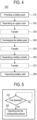
- FIG. 4 is a flowchart for an automated battery disassembly method 200 in an embodiment.
- FIG. 5 is a flowchart for a fire monitoring process 290 performed at each worktable.
- FIG. 6 illustrates a disassembly method for the battery module in an embodiment.
- FIG. 7 shows photographs of components separated by the automated battery disassembly system.
- the automated battery disassembly method 200 will be described using the components of the automated battery disassembly system 100 shown in FIGS. 1 to 3 . However, it is not required that the automated battery disassembly method 200 shown in FIGS. 4 and 5 is necessarily performed using the automated battery disassembly system 100 shown in FIGS. 1 to 3 .
- the specific operations in the automated battery disassembly method 200 described below may be performed by the controller 170 of the automated battery disassembly system 100.
- the operations of the transfer device 120, the robot device 130, and the fire extinguishing device 160 may be controlled by the controller 170.
- the operation of disassembling a specific component of the battery pack by the robot device 130 may be understood as that the controller 170 controlling the robot device 130 to disassemble a specific component of the battery pack.
- the operation of transferring the battery pack from the first worktable 111 to the second worktable 114 by the transfer device 120 may be understood as the controller 170 controlling the transfer device 120 to transfer the battery pack from the first worktable 111 to the second worktable 114.
- the automated battery disassembly method 200 may include step 210 of providing a battery pack, step 220 of separating an upper cover from the battery pack, step 240 of discharging the battery pack, step 260 of separating a battery module from the battery pack, and step 280 of separating battery cells from the battery module.
- the above steps may be performed in different worktables. In this case, after a specific step is finished and before a subsequent step is performed, the battery pack or the battery module may be transferred to a worktable where the subsequent step is performed. However, the transfer between steps is not essential. For example, if two different steps can be performed at the same time on one worktable, the transfer between the two steps may be omitted.
- the battery pack provided to the automated battery disassembly system 100 according to step 210 of providing the battery pack may be transferred to and placed in a waiting zone 101 by a transportation device (e.g., an automated guided vehicle (AGV)).
- the battery pack may be provided in a state of being disposed on a pallet, and the transportation device may move the battery pack and the pallet to the waiting zone 101.
- the transfer device 120 transfers the battery packs in the waiting zone 101 to the first worktable 111.
- the pallet on which the battery pack is disposed before the battery pack is connected to the transfer device 120 may be aligned at a specific position in the waiting zone 101 to facilitate the transfer by the transfer device 120.
- step 220 of separating the upper cover is performed.
- the robot devices 131 and 132 check the top of the battery pack through the vision system 140, and use various tools such as a bolt driver and a laser cutter to separate the upper cover from the battery pack. Since the battery pack has various shapes depending on the manufacturer or model, the tool provided in the robot device 130 or the movement of the robot device 130 may be appropriately determined according to the shape of the battery pack.
- the upper cover separated from the battery pack may be transferred to and stacked in the upper cover storage box 31 through the transfer device 120.
- step 240 of discharging the battery pack As step 240 of discharging the battery pack is performed on the discharging worktable 112 or 113, step 230 of transferring the battery pack from the first worktable to the discharging worktable 112 or 113 may be performed.
- Step 240 of discharging the battery pack may include a first discharge step using the discharger 151 and a second discharge step using the short-circuiting discharge performed after the first discharge step.
- the fifth robot 135 may use a dedicated jig to separate a battery management system (BMS) from the battery back.
- BMS battery management system
- the fifth robot 135 may use the vision system 140 and the dedicated jig to separate the BMS.
- the BMS may be transferred to and stored in a BMS storage box by the robot device 130.
- the robot device 130 may connect the battery pack to the discharger 151 to discharge the battery pack.
- the battery pack is connected to the discharger 151 and is discharged.
- the robot device 130 may connect the battery pack and the discharger 151 using a dedicated discharge jig.
- the battery pack may be connected to the discharger 151 and discharged until the battery pack is in a state of charge (SoC) at which the voltage of the battery pack becomes 30 V or less.
- SoC state of charge
- the discharging using the discharger may be performed for about 1 to 4 hours depending on the residual energy of the battery pack so that the voltage of the battery pack becomes 30V or less.
- residual energy may be recovered and used as an auxiliary power source for the system 100.
- the voltage of the battery pack may rises again to, for example, 30 V or more.
- the battery pack may be connected to the discharger 151 again and discharged until the voltage of the battery pack is stabilized to 30 V or less.
- the additional discharging may be performed on the second discharging worktable 113 after the battery pack is transferred to the second discharging worktable 113.
- the battery pack primarily discharged by the discharger 151 is coupled to the short-circuiting discharge jig by the fifth robot 135.
- the positive and negative terminals of the battery pack are short-circuited to each other.
- the battery pack may be transferred to and mounted on a short-circuiting discharge rack 22 by the transfer device 120. Even if the battery pack is discharged by the discharger 151, a certain amount of electric energy remains in the battery pack. Therefore, the stability of the subsequent disassembling step can be secured by performing short-circuiting discharge until the voltage of the battery pack becomes about 0.2 V or less.
- the battery pack may be short-circuit-discharged for a predetermined time, for example, 12 to 24 hours after being transferred to the short-circuiting discharge rack 22.
- the short-circuiting discharge rack 22 is composed of, for example, six 4-tier drawers.
- the above-described discharging may be performed by the controller 190.
- the controller 190 may discharge the battery pack for 1 hour to 4 hours by using the discharger 151 according to the residual energy of the battery pack so that the voltage of the battery pack becomes 30 V or less.
- the controller 190 may additionally discharge the battery pack by using the discharger 151 when the voltage of the battery pack rises again after the battery pack is discharged by using the discharger 151.
- the controller 190 may discharge the battery pack by using the short-circuiting discharge jig so that the voltage of the battery pack becomes 0.2 V or less.
- Discharging the battery pack using the short-circuiting discharge jig means discharging the battery pack in a state in which the short-circuiting discharge jig is coupled to the battery pack.
- the battery pack may be temporarily placed on the second discharging worktable 113 before being transferred to the short-circuiting discharge rack 22.
- the short-circuiting discharge jig may be mounted on the battery pack when the battery pack is placed on the first discharging worktable 112 or the second discharging worktable 113.
- step 260 of separating the battery module is performed on the first worktable 111. Accordingly, before step 260 of separating the battery module is performed, step 250 of transferring the battery pack from the discharging worktable 112 or 113 to the first worktable 111 is performed.
- step 250 of transferring the battery pack from the discharging worktable 112 or 113 to the first worktable 111 is performed.
- the transfer device 120 transfers the discharged battery pack from the short-circuiting discharge rack 22 to the first worktable 111.
- Step 260 of separating the battery module from the battery pack may be performed on the first worktable 111.
- the short-circuiting discharge jig which was coupled to the battery pack in step 240 of discharging the battery pack, may be removed by the robot device 130. The removed short-circuiting discharge jig is transferred to and stored at a designated place.
- the first robot 131 may check a component to be disassembled using the vision system 140, and may use the bolt driver and the tongs to disassemble and remove various bolts, cables, and the like connected to the battery module in the battery pack.
- the second robot 132 may check a components to be disassembled by the vision system 140, and may disassemble and cut brackets, plastics, and the like using a laser cutting machine and a cutter. The disassembled and cut components may be classified by type and loaded into the dismantling box 34.
- battery modules may be disposed in two layers. In this case, first, the upper battery module disposed on the upper layer may be separated from the battery pack, and then the lower battery module disposed on the lower layer may be separated from the battery pack. After the battery module is separated, the remaining lower cover of the battery pack may be transferred to the lower cover storage box 32 by the transfer device 120.
- the battery module may be separated from the battery pack after the cables and accessories connected to the battery module and the components for fixing the battery module to the battery pack are removed.
- the transfer device 120 may clamp and transfer the battery module to the second worktable 114. A portion of the battery module transferred to the second worktable 114 may be cut by the third robot 133. The third robot 133 may cut a specific portion of the battery module after locating the cutting tool at an accurate position using the vision system 140.
- the third robot 133 may use a cutting tool (e.g., a rotary saw) to cut both ends of the battery module so that the battery cells disposed in the battery module are not cut.
- a cutting tool e.g., a rotary saw
- the battery module 10 includes cell assemblies 11 arranged in one direction.
- the cell assembly 11 includes at least one battery cell 14 therein. That is, the battery module 10 includes a plurality of battery cells 14 arranged in one direction.
- the cell assemblies 11 are surrounded and fixed to each other by an end plate 12 and a cover frame 13.
- Each of the battery cells 14 includes a body 14a extending in a longitudinal direction perpendicular to the arrangement direction of the battery cells 14 and electrode leads 14b extending from longitudinal ends of the body 14a.
- An electrode assembly is disposed inside the body 14a.
- the electrode assembly is provided in the form of stacking positive electrode plates, negative electrode plates, and separators.
- the positive electrode plate and the negative electrode plate are connected to different electrode leads 14b.
- the cutting tool provided in the third robot 133 may cut the battery module 10 without cutting the body 14a of the battery cell 14.
- the cutting tool may cut the battery module 10 in the vertical direction (VD) along a line L extending in the arrangement direction of the battery cells 14 and passing through the outside of the body 14a of the battery cell 14.
- the line L may pass over the electrode lead 14b of the battery cell 14.
- the electrode leads 14b of the battery cells 14 may be exposed on the cut surface (see "cut portion of the battery module" in FIG. 7 ).
- One or more second worktables 114 and one or more third robots 133 may be provided.
- two second worktables 114 and two third robots 133 may be provided. Since it takes a relatively long time to cut both ends of the battery module, the disassembly speed of the battery pack can be increased by using two or more second worktables 114 and two or more third robots 133.
- the battery module on the first worktable 111 is transferred by the transfer device 120 to the other second worktable 114 and then cut by the third robot 133 installed near the other second worktable 114.
- the battery module separated on the second worktable 114 as described above goes through step 270 of transferring the battery module to the third worktable 115 by the transfer device 120.
- step 280 of separating the battery cells from the battery module is performed.
- the battery module is loaded on the third worktable 115 by the transfer device 120, the battery module is centered on the third worktable 115 and then clamped.
- the battery module fixed to the third worktable 115 is disassembled by the fourth robot 134.
- the fourth robot 134 may check a target to be disassembled by the vision system 140 and may use a vacuum gripper and a dismantling jig mounted on the fourth robot 134 to remove plastics, a cell protection aluminum cover, and other unnecessary elements from the battery module and separate the battery cells.
- the battery cells are stored in the cell box 33 by the fourth robot 134.
- a transportation device such as an AGV or the like automatically moves the cell box 33 to a storage space.
- the storage boxes e.g., the upper cover storage box 31 and the lower cover storage box 32
- the storage boxes for storing other components separated from the battery pack are also automatically moved to a designated place by the transportation device when the storage boxes are filled with a certain number of other components.
- the separated battery cells go through a recycling process. For example, a process of extracting valuable metals or the like from the battery cells may be performed.
- the automated battery disassembly method 200 may include a fire monitoring step 290. Whether or not a fire occurs may be monitored while performing the battery pack disassembly process.
- the fire monitoring step 290 includes step 291 of determining whether or not a fire has occurred in the battery pack or the battery module disposed on the worktable while performing step 220 of separating the upper cover from the battery pack, step 240 of discharging the battery pack, step 260 of separating the battery module from the battery pack, and step 280 of separating the battery cells from the battery module. If it is determined that a fire has occurred, the fire extinguishing device 160 is operated (292). For example, a fire may be extinguished by submerging the worktable in the water tank.
- the battery pack and the battery module are automatically disassembled by using automation devices such as the transfer device 120 and the robot device 130 instead of manual operations.
- automation devices such as the transfer device 120 and the robot device 130 instead of manual operations.
Landscapes
- Engineering & Computer Science (AREA)
- Mechanical Engineering (AREA)
- General Chemical & Material Sciences (AREA)
- Manufacturing & Machinery (AREA)
- Chemical & Material Sciences (AREA)
- Chemical Kinetics & Catalysis (AREA)
- Electrochemistry (AREA)
- Robotics (AREA)
- Environmental & Geological Engineering (AREA)
- Public Health (AREA)
- Health & Medical Sciences (AREA)
- Business, Economics & Management (AREA)
- Emergency Management (AREA)
- Sustainable Development (AREA)
- Life Sciences & Earth Sciences (AREA)
- Secondary Cells (AREA)
- Processing Of Solid Wastes (AREA)
- Primary Cells (AREA)
Abstract
Description
- The present disclosure relates to an automated battery disassembly system. More specifically, the present disclosure pertains to a method for automatically disassembling a battery pack or a battery module used in an electric vehicle or an energy storage device.
- Recently, a lithium-ion battery is used in electric vehicles and may be composed of four elements, i.e., a cathode material, an anode material, an electrolyte, and a battery separator. A nickel ternary (Li-Co or Li-Mn) battery and a lithium iron phosphate battery using iron instead of cobalt are used depending on the material used as a cathode material. A variety of batteries including an all-solid-state battery are expected to be used in order to reduce the fire hazard of an electrolyte.
- Secondary batteries account for 30% of the life cycle's carbon footprint of electric vehicles. Metal materials such as nickel, cobalt, and manganese account for a high carbon footprint. Most of carbon are generated in the mining and refining process of raw materials. The reuse and recycling of secondary batteries may make a great contribution to reducing greenhouse gas emissions for the transition to a carbon-neutral society by 2050.
- In the future, as the amount of waste batteries discarded after several years of use increases with the growth of the electric vehicle market, the battery recycling industry for recycling and reuse of waste batteries will be expanded. By recovering and recycling valuable metals (nickel, cobalt, manganese, copper, lithium, etc.) essential for battery manufacture through this battery recycling, it is possible not only to achieve resource recycling and economic benefit creation, but also to reduce the environmental pollution caused by the metal harvesting process.
- Conventionally, in order to recycle and reuse a waste battery pack, a worker has to directly disassemble the battery pack using a tool, extract and discharge a battery module. At this time, the battery discharge is performed using saline water. This saline water discharge method uses saline water obtained by diluting sodium chloride (NaCl) or calcium chloride (CaCl2) with water at a concentration of 3% to 3.5%. The saline water discharge method takes a long time from at least 8 hours to 10 days or more. Care should be taken because fire and explosion accidents may occur during the saline water discharge process. Heavy metal leakage and wastewater treatment may result in high costs, and may require a large workspace. The saline-water-discharged battery module has to be dried and then directly disassembled again to extract battery cells.
- Since most of the conventional battery pack recycling methods described above are performed manually, they are very inefficient and time-consuming. In addition, a large number of people are required for disassembly works, and there is a high risk of workers being exposed to harmful environments, which may cause various problems.
- An object of the present disclosure is to provide an automated battery disassembly system capable of solving the above problems.
- According to one embodiment, an automated battery disassembly system includes: a workstation including a first worktable, a second worktable, a third worktable, and a discharging worktable; a discharging device; a robot device; a transfer device; and a controller electrically connected to the robot device and the transfer device, wherein the controller is configured to control the robot device to: when a battery pack is disposed on the first worktable, separate an upper cover from the battery pack; when the battery pack is disposed on the discharging worktable, discharge the battery pack by connecting the battery pack to the discharging device; when the discharged battery pack is disposed on the second worktable, separate a battery module from the discharged battery pack; and when the battery module is disposed on the third worktable, separate battery cells from the battery module.
- The controller may be configured to control the transfer device to: after the separating the upper cover from the battery pack and before the discharging the battery pack, transfer the battery pack which is disposed on the first worktable and from which the upper cover is separated to the discharging worktable; after the discharging the battery pack and before the separating the battery module from the discharged battery pack, transfer the discharged battery pack disposed on the discharging worktable to the second worktable; and after the separating the battery module from the discharged battery pack and before the separating the battery cells from the battery module, transfer the battery module disposed on the second worktable to the third worktable.
- The system may further include: a fire extinguishing device including a water tank connected to the controller and configured to be filled with fire extinguishing water, wherein the controller may be configured to control the fire extinguishing device to accommodate the battery pack disposed on the workstation into the water tank.
- The system may further include: a vision system electrically connected to the controller, wherein the controller may be configured to disassemble components of the battery pack disposed on the workstation by controlling the robot device based on data obtained through the vision system.
- The system may further include: a storage box, wherein the controller may be configured to control the robot device to move the components separated from the battery pack to the storage box.
- The discharging device may include a discharger and a short-circuiting discharge jig, and the controller may be configured to control the robot device to connect the battery pack disposed on the discharging worktable to the discharger to discharge the battery pack, and then control the robot device to connect the battery pack to the short-circuiting discharge jig to short-circuit-discharge the battery pack.
- The controller may be configured to discharge the battery pack by using the discharger for 1 hour to 4 hours according to a residual energy of the battery pack so that a voltage of the battery pack is 30 V or less, and to discharge the battery pack by using the short-circuiting discharge jig so that the voltage of the battery pack is 0.2 V or less.
- The battery module may include a plurality of battery cells arranged in a first direction, each of the battery cells may include a body extending in a longitudinal direction perpendicular to the first direction and electrode leads extending from longitudinal ends of the body, and the separating the battery cells from the battery module may include cutting the battery module along a line parallel to the first direction and passing over the electrode leads when the battery module is viewed from above.
- The automated battery disassembly system according to the present disclosure is capable of minimizing the input of workers during a waste battery disassembling work, automatically disassembling and separating a battery pack and a battery module using a robot device and a automation device, avoiding exposure of workers to harmful environments, improving a waste battery disassembly ability, and minimizing the number of workers. Furthermore, the automated battery disassembly system according to the present disclosure is capable of enhancing the battery disassembly productivity.
-
-
FIG. 1 is a configuration diagram of an automated battery disassembly system according to one embodiment. -
FIG. 2 is a plan view of the automated battery disassembly system according to one embodiment. -
FIG. 3 is a side view of the automated battery disassembly system shown inFIG. 2 . -
FIG. 4 is a flowchart of an automated battery disassembly method according to one embodiment. -
FIG. 5 is a view showing a fire monitoring process performed at each worktable. -
FIG. 6 is a view showing an automated battery disassembly method according to one embodiment. -
FIG. 7 shows photographs of components separated by the automated battery disassembly system. - Embodiments of the present disclosure are illustrated for describing the technical scope of the present disclosure. The scope of the claims according to the present disclosure is not limited to the embodiments described below or to the detailed descriptions of these embodiments.
- All technical or scientific terms used herein have meanings that are generally understood by a person having ordinary knowledge in the art to which the present disclosure pertains, unless otherwise specified. The terms used herein are selected for only more clear illustration of the present disclosure, and are not intended to limit the scope of claims in accordance with the present disclosure.
- The expressions "include", "provided with", "have" and the like used herein should be understood as open-ended terms connoting the possibility of inclusion of other embodiments, unless otherwise mentioned in a phrase or sentence including the expressions.
- A singular expression can include meanings of plurality, unless otherwise mentioned, and the same is applied to a singular expression stated in the claims.
- The terms "first", "second", etc. used herein are used to identify a plurality of components from one another, and are not intended to limit the order or importance of the relevant components.
- When a certain component is described as "coupled to" or "connected to" another component, this should be understood as having meaning that the certain component may be coupled or connected directly to the other component or that the certain component may be coupled or connected to the other component via a new intervening component.
- Hereinafter, embodiments of the present disclosure will be described with reference to the accompanying drawings. In the accompanying drawings, like or relevant components are indicated by like reference numerals. In the following description of embodiments, repeated descriptions of the identical or relevant components will be omitted. However, even if a description of a component is omitted, such a component is not intended to be excluded in an embodiment.
-
FIG. 1 is a configuration diagram of an automatedbattery disassembly system 100 according to one embodiment.FIG. 2 is a plan view of the automatedbattery disassembly system 100 according to one embodiment.FIG. 3 is a side view of the automatedbattery disassembly system 100 shown inFIG. 2 . - The automated
battery disassembly system 100 is configured to disassemble a battery pack used in an electric vehicle or the like. The battery pack is disassembled to recycle or reuse the components inside the battery pack. By extracting battery cells from the battery pack, the materials constituting the battery cells can be recovered and recycled. Alternatively, the battery cells extracted from the battery pack may be reused for other purposes. For example, an energy storage system (ESS) may use the battery cells separated from the battery pack used in an electric vehicle. - The automated
battery disassembly system 100 includes aworkstation 110, atransfer device 120, and arobot device 130. - The
workstation 110 is configured to allow the battery pack to be disposed thereon. The automatedbattery disassembly system 100 may include two or more worktables. For example, referring toFIG. 2 , the workstation may include a plurality ofworktables workstation 110 may refer to each or all of the plurality ofworktables - Different processes may be performed on different worktables. For example, when the battery pack is disposed on the
first worktable 111, the upper cover of the battery pack may be disassembled, and when the battery pack is disposed on thesecond worktable 114, the battery cells may be separated from a battery module. - The
workstation 110 may include dischargingworktables device 150 and thereby the battery pack may be discharged. - The
workstation 110 may include a first dischargingworktable 112 manufactured in a turntable structure and configured to be rotatable. The first dischargingworktable 112 may rotate the battery pack to a position or direction suitable for discharging. Although discharging connectors in battery packs may be positioned variously depending on the manufacturer and model type, various types of battery packs can be handled by using the rotatable first dischargingworktable 112. - A second discharging
worktable 113 may be used as a standby place for the battery pack having been discharged by adischarger 151 before transferring the battery pack to a short dischargingrack 22. In another embodiment, theworkstation 110 may include a second dischargingworktable 113 specialized for a battery pack of a specific model. - The automated
battery disassembly system 100 may include two or more first dischargingworktables 112 and two or more second dischargingworktables 113. Referring toFIG. 2 , two first dischargingworktables 112 and two second dischargingworktables 113 may be provided. - As well as the process of discharging the battery pack, other processes may also be performed on the discharging
worktables worktables robot device 130 may separate and remove a battery management system (BMS) from the battery pack. - The
transfer device 120 is configured to transfer the battery pack to theworkstation 110 or move the battery pack disposed on theworkstation 110 to another location. Thetransfer device 120 may include a gantry and a jig installed on the gantry. Thetransfer device 120 may clamp a battery pack or a component (e.g., a battery module) inside the battery pack using the jig installed on the gantry, and then may transfer the battery pack to another location. For example, thetransfer device 120 may transfer the battery pack disposed on thefirst worktable 111 to the first dischargingworktable 112. For another example, thetransfer device 120 may transfer the battery module inside the battery pack disposed on thefirst worktable 111 to thesecond worktable 114. - The
robot device 130 is a device for disassembling the battery pack, and may be configured to disassemble and separate components of the battery pack from the battery pack. For example, therobot device 130 may disassemble the battery pack using a robot arm and various tools (e.g., a bolt driver, laser cutter, tongs, saw, etc.) mounted on the robot arm. A laser cutting tool, a bolting processing tool, a cable cutting tool, a cover handling tool, a scrap handling tool, a cable handling tool, and the like are provided around therobot device 130. Therobot device 130 may replace the tool coupled to the robot arm as needed. Therobot device 130 may mount other components on the battery pack. For example, therobot device 130 may mount a discharging jig on the battery pack. The battery pack mounted with the discharging jig may be connected to a discharger and may be discharged. - The
robot device 130 may be configured to transfer the components separated from the battery pack to another location. Therobot device 130 may transfer the components (upper cover, lower cover, battery cell, etc.) disassembled from the battery pack to storage boxes (e.g., uppercover storage box 31, lowercover storage box 32,cell box 33, and dismantling box 34). - A plurality of
robot devices 130 may be provided to disassemble the battery pack quickly and efficiently. For example, therobot device 130 includes afirst robot 131 and asecond robot 132 configured to perform works on an object disposed on thefirst worktable 111, athird robot 133 configured to perform works on an object disposed on thesecond worktable 114, afourth robot 134 configured to perform works on an object disposed on thethird worktable 115, and afifth robot 135 configured to perform works on an object disposed on disposed on the dischargingworktables FIG. 2 are nothing more than examples. In other embodiments, the robots may be arranged in other numbers or at other locations. - The automated
battery disassembly system 100 may include avision system 140. Thevision system 140 may provide information necessary for controlling the movement of therobot device 130 in association with therobot device 130. The automatedbattery disassembly system 100 may control therobot device 130 based on the data acquired through thevision system 140 to disassemble components of the battery pack disposed on theworkstation 110. - The
vision system 140 captures images of the object of therobot device 130 with a camera, so that therobot device 130 can accurately perform works (e.g., removing bolts to remove the battery pack cover, cutting the cable inside the battery pack, cutting the battery module, etc.) on the object. In addition, the type of battery pack may be checked using thevision system 140, and therobot device 130 may re-perform necessary works based on the result of check. - The
vision system 140 may be provided for eachrobot device 130 or for each worktable. For example, thevision system 140 may be provided in each of the plurality ofrobot devices 130 provided in the automatedbattery disassembly system 100. InFIG. 1 , therobot device 130 and thevision system 140 are shown as separate blocks for the sake of convenience of description. However, thevision system 140 may be provided as a part of therobot device 130. Unless otherwise specified, it should be understood that the works of disassembling and separating the battery pack or battery module by therobot device 130 are performed using thevision system 140. - The automated
battery disassembly system 100 may include a dischargingdevice 150. The battery pack can be safely disassembled by discharging the battery pack before separating the components inside the battery pack (e.g., battery modules, battery cells, and battery management system (BMS)). The dischargingdevice 150 may include adischarger 151 for forcibly discharging the battery pack and a short-circuiting discharge jig configured to short-circuit the battery pack. The short-circuiting discharge jig is a jig composed of a bus bar and a cable, and is configured to short-circuit the (+) terminal and (-) terminal of the battery pack. The short-circuiting discharge jig may be mounted on the battery pack by therobot device 130. - The automated
battery disassembly system 100 may include afire extinguishing device 160. Thefire extinguishing device 160 may extinguish a fire when a fire occurs in the battery pack disposed on theworkstation 110. Thefire extinguishing device 160 includes a water tank configured to be filled with fire extinguishing water, so that the workstation can be accommodated in the water tank when a fire occurs. A fire can be extinguished by accommodating theworkstation 110 into the water tank filled with water. Accommodating theworkstation 110 in the water tank in the present disclosure means that the worktables constituting the workstation enters the water tank. - The
fire extinguishing device 160 may include a fire detection sensor, and may accommodate the worktables in the water tank based on a signal acquired through the fire detection sensor. In the present disclosure, the fire detection sensor is nothing more than an example of a means for detecting a fire, and a fire may be detected by a component other than the fire detection sensor provided in the fire extinguishing device. - The water tank may be provided under the
workstation 110. When a fire occurs in the battery pack, the piston supporting the worktables descends, so that theworkstation 110 and the battery pack on theworkstation 110 can be submerged in the water tank. If the fire continues, low-temperature extinguishing water may be additionally supplied from the outside to the water tank. Thefire extinguishing device 160 may include a drainage part for draining the fire extinguishing water in the water tank to the outside. The drained fire extinguishing water may be cooled again and introduced into the water tank. Thefire extinguishing device 160 may include a temperature sensor. Thefire extinguishing device 160 may measure the temperature of the fire extinguishing water in the water tank using the temperature sensor, and may supply low-temperature fire extinguishing water to the water tank based on the measured temperature. - The automated
battery disassembly system 100 includes acontroller 170. Thecontroller 170 controls an operation of controlling the automatedbattery disassembly system 100. For example, thecontroller 170 may control the disassembly of the battery pack by therobot device 130, the transfer of the battery pack or the components of the battery pack by thetransfer device 120, the operation of thefire extinguishing device 160, and the like. Thecontroller 170 is not limited to one physical control device, and may be understood to be a concept including all control devices involved in controlling the automatedbattery disassembly system 100. For example, thefire extinguishing device 160 may include its own control device that controls the operation of thefire extinguishing device 160, and although thecontroller 170 is shown as a block separate from thefire extinguishing device 160 inFIG. 1 , it may be understood that thecontroller 170 includes a control device for thefire extinguishing device 160. - The automated
battery disassembly system 100 according to the present disclosure will be described as being used in a method or process of disassembling a battery pack. However, the automated battery disassembly system may be used not only in disassembling the battery pack but also in disassembling various types of energy storage devices (e.g., battery modules) including secondary batteries. - The automated
battery disassembly system 100 described with reference toFIGS. 2 and3 is nothing more than an example, and may be implemented in an appropriate form depending on the location where the system is to be installed or the type of battery pack handled by the system. -
FIG. 4 is a flowchart for an automatedbattery disassembly method 200 in an embodiment.FIG. 5 is a flowchart for a fire monitoring process 290 performed at each worktable.FIG. 6 illustrates a disassembly method for the battery module in an embodiment.FIG. 7 shows photographs of components separated by the automated battery disassembly system. Hereinafter, the automatedbattery disassembly method 200 will be described using the components of the automatedbattery disassembly system 100 shown inFIGS. 1 to 3 . However, it is not required that the automatedbattery disassembly method 200 shown inFIGS. 4 and 5 is necessarily performed using the automatedbattery disassembly system 100 shown inFIGS. 1 to 3 . - The specific operations in the automated
battery disassembly method 200 described below may be performed by thecontroller 170 of the automatedbattery disassembly system 100. The operations of thetransfer device 120, therobot device 130, and thefire extinguishing device 160 may be controlled by thecontroller 170. For example, the operation of disassembling a specific component of the battery pack by therobot device 130 may be understood as that thecontroller 170 controlling therobot device 130 to disassemble a specific component of the battery pack. For another example, the operation of transferring the battery pack from thefirst worktable 111 to thesecond worktable 114 by thetransfer device 120 may be understood as thecontroller 170 controlling thetransfer device 120 to transfer the battery pack from thefirst worktable 111 to thesecond worktable 114. - The automated
battery disassembly method 200 may include step 210 of providing a battery pack, step 220 of separating an upper cover from the battery pack, step 240 of discharging the battery pack, step 260 of separating a battery module from the battery pack, and step 280 of separating battery cells from the battery module. The above steps may be performed in different worktables. In this case, after a specific step is finished and before a subsequent step is performed, the battery pack or the battery module may be transferred to a worktable where the subsequent step is performed. However, the transfer between steps is not essential. For example, if two different steps can be performed at the same time on one worktable, the transfer between the two steps may be omitted. - The battery pack provided to the automated
battery disassembly system 100 according to step 210 of providing the battery pack may be transferred to and placed in a waitingzone 101 by a transportation device (e.g., an automated guided vehicle (AGV)). The battery pack may be provided in a state of being disposed on a pallet, and the transportation device may move the battery pack and the pallet to the waitingzone 101. Thetransfer device 120 transfers the battery packs in the waitingzone 101 to thefirst worktable 111. The pallet on which the battery pack is disposed before the battery pack is connected to thetransfer device 120 may be aligned at a specific position in the waitingzone 101 to facilitate the transfer by thetransfer device 120. - After the
transfer device 120 transfers the battery pack to thefirst worktable 111, step 220 of separating the upper cover is performed. When the battery pack is disposed on thefirst worktable 111, therobot devices vision system 140, and use various tools such as a bolt driver and a laser cutter to separate the upper cover from the battery pack. Since the battery pack has various shapes depending on the manufacturer or model, the tool provided in therobot device 130 or the movement of therobot device 130 may be appropriately determined according to the shape of the battery pack. The upper cover separated from the battery pack may be transferred to and stacked in the uppercover storage box 31 through thetransfer device 120. - The battery pack that has gone through
step 220 of separating the upper cover is subjected to step 240 of discharging the battery pack. Asstep 240 of discharging the battery pack is performed on the dischargingworktable worktable - Step 240 of discharging the battery pack may include a first discharge step using the
discharger 151 and a second discharge step using the short-circuiting discharge performed after the first discharge step. - After the battery pack from which the upper cover is separated is transferred to the first discharging
worktable 112 by thetransfer device 120, thefifth robot 135 may use a dedicated jig to separate a battery management system (BMS) from the battery back. Thefifth robot 135 may use thevision system 140 and the dedicated jig to separate the BMS. When automatically separated by thefifth robot 135, the BMS may be transferred to and stored in a BMS storage box by therobot device 130. - When the separation of the BMS is completed, the
robot device 130 may connect the battery pack to thedischarger 151 to discharge the battery pack. The battery pack is connected to thedischarger 151 and is discharged. Therobot device 130 may connect the battery pack and thedischarger 151 using a dedicated discharge jig. The battery pack may be connected to thedischarger 151 and discharged until the battery pack is in a state of charge (SoC) at which the voltage of the battery pack becomes 30 V or less. For example, the discharging using the discharger may be performed for about 1 to 4 hours depending on the residual energy of the battery pack so that the voltage of the battery pack becomes 30V or less. After the battery pack is connected to thedischarger 151 and the state of charge is checked, residual energy may be recovered and used as an auxiliary power source for thesystem 100. - When the battery pack is rapidly discharged by using the
discharger 151, the voltage of the battery pack may rises again to, for example, 30 V or more. In this case, the battery pack may be connected to thedischarger 151 again and discharged until the voltage of the battery pack is stabilized to 30 V or less. The additional discharging may be performed on the second dischargingworktable 113 after the battery pack is transferred to the second dischargingworktable 113. - The battery pack primarily discharged by the
discharger 151 is coupled to the short-circuiting discharge jig by thefifth robot 135. When coupled to the short-circuiting discharge jig, the positive and negative terminals of the battery pack are short-circuited to each other. In that state, the battery pack may be transferred to and mounted on a short-circuiting discharge rack 22 by thetransfer device 120. Even if the battery pack is discharged by thedischarger 151, a certain amount of electric energy remains in the battery pack. Therefore, the stability of the subsequent disassembling step can be secured by performing short-circuiting discharge until the voltage of the battery pack becomes about 0.2 V or less. The battery pack may be short-circuit-discharged for a predetermined time, for example, 12 to 24 hours after being transferred to the short-circuiting discharge rack 22. The short-circuiting discharge rack 22 is composed of, for example, six 4-tier drawers. When thetransfer device 120 transfers the battery pack to which the short-circuiting discharge jig is attached, a designated drawer in the short-circuiting discharge rack 22 is opened. Thetransfer device 120 may put a battery pack equipped with the short-circuiting discharge jig into the opened drawer. - The above-described discharging may be performed by the controller 190. The controller 190 may discharge the battery pack for 1 hour to 4 hours by using the
discharger 151 according to the residual energy of the battery pack so that the voltage of the battery pack becomes 30 V or less. The controller 190 may additionally discharge the battery pack by using thedischarger 151 when the voltage of the battery pack rises again after the battery pack is discharged by using thedischarger 151. The controller 190 may discharge the battery pack by using the short-circuiting discharge jig so that the voltage of the battery pack becomes 0.2 V or less. Discharging the battery pack using the short-circuiting discharge jig means discharging the battery pack in a state in which the short-circuiting discharge jig is coupled to the battery pack. - After the discharging on the first discharging
worktable 112 by thedischarger 151 is finished, the battery pack may be temporarily placed on the second dischargingworktable 113 before being transferred to the short-circuiting discharge rack 22. The short-circuiting discharge jig may be mounted on the battery pack when the battery pack is placed on the first dischargingworktable 112 or the second dischargingworktable 113. - After
step 240 of discharging the battery pack is performed, the battery pack undergoesstep 260 of separating the battery module. Step 260 of separating the battery module is performed on thefirst worktable 111. Accordingly, beforestep 260 of separating the battery module is performed,step 250 of transferring the battery pack from the dischargingworktable first worktable 111 is performed. When the short-circuiting discharge is completed instep 240 of discharging the battery pack or when the complete discharge of the battery pack due to the short-circuiting discharge is confirmed, thetransfer device 120 transfers the discharged battery pack from the short-circuiting discharge rack 22 to thefirst worktable 111. - Step 260 of separating the battery module from the battery pack may be performed on the
first worktable 111. Before separating the battery module, the short-circuiting discharge jig, which was coupled to the battery pack instep 240 of discharging the battery pack, may be removed by therobot device 130. The removed short-circuiting discharge jig is transferred to and stored at a designated place. - When the battery pack is disposed on the
first worktable 111, thefirst robot 131 may check a component to be disassembled using thevision system 140, and may use the bolt driver and the tongs to disassemble and remove various bolts, cables, and the like connected to the battery module in the battery pack. Thesecond robot 132 may check a components to be disassembled by thevision system 140, and may disassemble and cut brackets, plastics, and the like using a laser cutting machine and a cutter. The disassembled and cut components may be classified by type and loaded into thedismantling box 34. - Inside the battery pack, battery modules may be disposed in two layers. In this case, first, the upper battery module disposed on the upper layer may be separated from the battery pack, and then the lower battery module disposed on the lower layer may be separated from the battery pack. After the battery module is separated, the remaining lower cover of the battery pack may be transferred to the lower
cover storage box 32 by thetransfer device 120. - The battery module may be separated from the battery pack after the cables and accessories connected to the battery module and the components for fixing the battery module to the battery pack are removed.
- The
transfer device 120 may clamp and transfer the battery module to thesecond worktable 114. A portion of the battery module transferred to thesecond worktable 114 may be cut by thethird robot 133. Thethird robot 133 may cut a specific portion of the battery module after locating the cutting tool at an accurate position using thevision system 140. - The
third robot 133 may use a cutting tool (e.g., a rotary saw) to cut both ends of the battery module so that the battery cells disposed in the battery module are not cut. For example, referring toFIG. 6 , thebattery module 10 includescell assemblies 11 arranged in one direction. Thecell assembly 11 includes at least onebattery cell 14 therein. That is, thebattery module 10 includes a plurality ofbattery cells 14 arranged in one direction. Thecell assemblies 11 are surrounded and fixed to each other by anend plate 12 and acover frame 13. Each of thebattery cells 14 includes abody 14a extending in a longitudinal direction perpendicular to the arrangement direction of thebattery cells 14 and electrode leads 14b extending from longitudinal ends of thebody 14a. An electrode assembly is disposed inside thebody 14a. The electrode assembly is provided in the form of stacking positive electrode plates, negative electrode plates, and separators. The positive electrode plate and the negative electrode plate are connected to different electrode leads 14b. The cutting tool provided in thethird robot 133 may cut thebattery module 10 without cutting thebody 14a of thebattery cell 14. For example, when thebattery module 10 is viewed from above, the cutting tool may cut thebattery module 10 in the vertical direction (VD) along a line L extending in the arrangement direction of thebattery cells 14 and passing through the outside of thebody 14a of thebattery cell 14. For example, when viewed from above thebattery module 10, the line L may pass over theelectrode lead 14b of thebattery cell 14. As a result, the electrode leads 14b of thebattery cells 14 may be exposed on the cut surface (see "cut portion of the battery module" inFIG. 7 ). - One or more
second worktables 114 and one or morethird robots 133 may be provided. For example, referring toFIG. 2 , twosecond worktables 114 and twothird robots 133 may be provided. Since it takes a relatively long time to cut both ends of the battery module, the disassembly speed of the battery pack can be increased by using two or moresecond worktables 114 and two or morethird robots 133. For example, when the cutting operation for the battery module is in progress on onesecond worktable 114, the battery module on thefirst worktable 111 is transferred by thetransfer device 120 to the othersecond worktable 114 and then cut by thethird robot 133 installed near the othersecond worktable 114. - The battery module separated on the
second worktable 114 as described above goes throughstep 270 of transferring the battery module to thethird worktable 115 by thetransfer device 120. - When the battery module is prepared on the
third worktable 115, step 280 of separating the battery cells from the battery module is performed. When the battery module is loaded on thethird worktable 115 by thetransfer device 120, the battery module is centered on thethird worktable 115 and then clamped. The battery module fixed to thethird worktable 115 is disassembled by thefourth robot 134. Thefourth robot 134 may check a target to be disassembled by thevision system 140 and may use a vacuum gripper and a dismantling jig mounted on thefourth robot 134 to remove plastics, a cell protection aluminum cover, and other unnecessary elements from the battery module and separate the battery cells. The battery cells are stored in thecell box 33 by thefourth robot 134. When a certain amount of battery cells is loaded into thecell box 33, a transportation device such as an AGV or the like automatically moves thecell box 33 to a storage space. The storage boxes (e.g., the uppercover storage box 31 and the lower cover storage box 32) for storing other components separated from the battery pack are also automatically moved to a designated place by the transportation device when the storage boxes are filled with a certain number of other components. - The separated battery cells go through a recycling process. For example, a process of extracting valuable metals or the like from the battery cells may be performed.
- The automated
battery disassembly method 200 may include a fire monitoring step 290. Whether or not a fire occurs may be monitored while performing the battery pack disassembly process. - The fire monitoring step 290 includes
step 291 of determining whether or not a fire has occurred in the battery pack or the battery module disposed on the worktable while performingstep 220 of separating the upper cover from the battery pack, step 240 of discharging the battery pack, step 260 of separating the battery module from the battery pack, and step 280 of separating the battery cells from the battery module. If it is determined that a fire has occurred, thefire extinguishing device 160 is operated (292). For example, a fire may be extinguished by submerging the worktable in the water tank. - According to the present disclosure, in order to recycle the waste battery, the battery pack and the battery module are automatically disassembled by using automation devices such as the
transfer device 120 and therobot device 130 instead of manual operations. As a result, it is possible to effectively recycle the battery pack of the electric vehicle, and it is possible to prevent or minimize exposure of workers to hazardous substances that may be generated during the disassembly of the battery. - Although the technical scope of the present disclosure has been described by the examples described in some embodiments and illustrated in the accompanying drawings, it should be noted that various substitutions, modifications, and changes can be made without departing from the scope of the present disclosure which can be understood by those skilled in the art to which the present disclosure pertains. In addition, it should be noted that that such substitutions, modifications and changes are intended to fall within the scope of the appended claims.
Claims (8)
- An automated battery disassembly system, comprising:a workstation including a first worktable, a second worktable, a third worktable, and a discharging worktable;a discharging device;a robot device;a transfer device; anda controller electrically connected to the robot device and the transfer device,wherein the controller is configured to control the robot device to:when a battery pack is disposed on the first worktable, separate an upper cover from the battery pack;when the battery pack is disposed on the discharging worktable, discharge the battery pack by connecting the battery pack to the discharging device;when the discharged battery pack is disposed on the second worktable, separate a battery module from the discharged battery pack; andwhen the battery module is disposed on the third worktable, separate battery cells from the battery module.
- The system of claim 1, wherein the controller is configured to control the transfer device to:after the separating the upper cover from the battery pack and before the discharging the battery pack, transfer the battery pack which is disposed on the first worktable and from which the upper cover is separated, to the discharging worktable;after the discharging the battery pack and before the separating the battery module from the discharged battery pack, transfer the discharged battery pack disposed on the discharging worktable to the second worktable; andafter the separating the battery module from the discharged battery pack and before the separating the battery cells from the battery module, transfer the battery module disposed on the second worktable to the third worktable.
- The system of claim 1, further comprising a fire extinguishing device including a water tank connected to the controller and configured to be filled with fire extinguishing water,
wherein the controller is configured to control the fire extinguishing device to accommodate the battery pack disposed on the workstation into the water tank. - The system of claim 1, further comprising a vision system electrically connected to the controller,
wherein the controller is configured to disassemble components of the battery pack disposed on the workstation by controlling the robot device based on data obtained through the vision system. - The system of claim 1, further comprising a storage box,
wherein the controller is configured to control the robot device to move the components separated from the battery pack to the storage box. - The system of claim 1,wherein the discharging device includes a discharger and a short-circuiting discharge jig, andwherein the controller is configured to control the robot device to connect the battery pack disposed on the discharging worktable to the discharger to discharge the battery pack, and then control the robot device to connect the battery pack to the short-circuiting discharge jig to short-circuit-discharge the battery pack.
- The system of claim 6, wherein the controller is configured to discharge the battery pack by using the discharger for 1 hour to 4 hours according to a residual energy of the battery pack so that a voltage of the battery pack is 30 V or less, and to discharge the battery pack by using the short-circuiting discharge jig so that the voltage of the battery pack is 0.2 V or less.
- The system of claim 1,wherein the battery module includes a plurality of battery cells arranged in a first direction, each of the battery cells including a body extending in a longitudinal direction perpendicular to the first direction and electrode leads extending from longitudinal ends of the body, andwherein the separating the battery cells from the battery module includes cutting the battery module along a line parallel to the first direction and passing over the electrode leads when the battery module is viewed from above.
Applications Claiming Priority (2)
| Application Number | Priority Date | Filing Date | Title |
|---|---|---|---|
| KR1020230057900A KR102607752B1 (en) | 2023-05-03 | 2023-05-03 | Automated disassembly system for battery |
| PCT/KR2023/011591 WO2023244095A2 (en) | 2023-05-03 | 2023-08-07 | Automatic battery dismantling system |
Publications (2)
| Publication Number | Publication Date |
|---|---|
| EP4443603A2 true EP4443603A2 (en) | 2024-10-09 |
| EP4443603A4 EP4443603A4 (en) | 2025-08-20 |
Family
ID=88689335
Family Applications (1)
| Application Number | Title | Priority Date | Filing Date |
|---|---|---|---|
| EP23754992.8A Pending EP4443603A4 (en) | 2023-05-03 | 2023-08-07 | AUTOMATIC BATTERY DISASSEMBLY SYSTEM |
Country Status (7)
| Country | Link |
|---|---|
| US (2) | US20240372167A1 (en) |
| EP (1) | EP4443603A4 (en) |
| JP (1) | JP7541200B2 (en) |
| CN (1) | CN119256425A (en) |
| CA (1) | CA3211707C (en) |
| MX (1) | MX2024000425A (en) |
| MY (1) | MY207372A (en) |
Families Citing this family (4)
| Publication number | Priority date | Publication date | Assignee | Title |
|---|---|---|---|---|
| US12263547B2 (en) * | 2023-05-22 | 2025-04-01 | Microsoft Technology Licensing, Llc | Computerized demanufacturing system |
| US20250042028A1 (en) * | 2023-08-02 | 2025-02-06 | Thoth Inc. | Method for dismantling battery components using a robot, a computing device in which such a method is implemented, and a system comprising the computing device |
| US20250214238A1 (en) * | 2023-12-29 | 2025-07-03 | Universe Energy, Inc. | Automated battery disassembly |
| AU2025234139B1 (en) * | 2024-11-25 | 2026-02-19 | Korea Zinc Co., Ltd. | Apparatus and method for managing battery |
Family Cites Families (24)
| Publication number | Priority date | Publication date | Assignee | Title |
|---|---|---|---|---|
| JP2005151679A (en) * | 2003-11-14 | 2005-06-09 | Shin Kobe Electric Mach Co Ltd | Battery voltage adjustment method |
| CN103178316B (en) | 2013-03-08 | 2015-06-17 | 广东邦普循环科技有限公司 | Novel electric vehicle power battery pack separation apparatus |
| CN105390764B (en) | 2015-11-24 | 2018-07-06 | 国联汽车动力电池研究院有限责任公司 | The disassembling method of highly pressurised liquid diced system and application thereof, waste and old lithium ion battery |
| CN206716705U (en) | 2017-04-12 | 2017-12-08 | 国网江苏省电力公司电力科学研究院 | An automatic dismantling and recycling system for waste electric energy meters |
| TWM549178U (en) | 2017-06-01 | 2017-09-21 | 中華精測科技股份有限公司 | System for automatically replacing battery of automatic guided vehicle |
| KR101827824B1 (en) | 2017-08-08 | 2018-02-09 | 한국지질자원연구원 | Apparatus for cutting and discharging battery |
| KR102175706B1 (en) | 2017-11-29 | 2020-11-06 | 허민 | Electrode lead cutting system of waste battery pack |
| CN108461856B (en) | 2018-02-26 | 2020-07-10 | 格林美股份有限公司 | Intelligent dismantling system for used power batteries |
| CN108390121A (en) * | 2018-04-08 | 2018-08-10 | 刘国云 | A kind of sorting equipment for scrap dry battery recycling |
| KR102671485B1 (en) * | 2018-10-18 | 2024-05-30 | 주식회사 엘지에너지솔루션 | Metal recovery method and system of waste battery |
| JP7755248B2 (en) | 2019-07-11 | 2025-10-16 | 学校法人早稲田大学 | Stabilization method for used lithium-ion batteries |
| US11345029B2 (en) | 2019-08-21 | 2022-05-31 | Mujin, Inc. | Robotic multi-gripper assemblies and methods for gripping and holding objects |
| CN110977021B (en) | 2019-11-21 | 2024-07-12 | 湖北金进自动化科技有限公司 | Deep disassembly method and device for power battery |
| CN112589276A (en) * | 2020-12-16 | 2021-04-02 | 深圳德龙激光智能有限公司 | Laser ablation flow guide discharging device for power battery disassembly |
| KR102358037B1 (en) * | 2021-03-11 | 2022-02-08 | (주)로파 | Learning-Based Decommissioning Robot Automation System for Electric Vehicle Waste Batteries |
| RU2767310C1 (en) | 2021-04-21 | 2022-03-17 | Федеральное государственное автономное образовательное учреждение высшего образования "Сибирский федеральный университет" | Method for disassembling used lead-acid batteries |
| KR102334855B1 (en) * | 2021-07-16 | 2021-12-03 | 에스아이에스 주식회사 | Batch processing system for waste lithium secondary battery |
| KR102334865B1 (en) * | 2021-07-16 | 2021-12-03 | 에스아이에스 주식회사 | Batch processing system for waste lithium secondary battery |
| KR102409527B1 (en) | 2022-01-25 | 2022-06-22 | (주)로파 | automated disassembly system for electric vehicle batteries using a rider sensor |
| CN114744321B (en) | 2022-05-07 | 2026-02-06 | 江西省智能产业技术创新研究院 | Fine disassembly system for scrapped power lithium battery cells |
| KR102512096B1 (en) | 2022-09-02 | 2023-03-20 | 에스아이에스 주식회사 | Dismantling system of spent lithium ion battery pack |
| KR102519579B1 (en) | 2022-10-18 | 2023-04-10 | (주)이에프씨 | Electrode collecting system for spent lithium ion battery |
| CN115911631B (en) | 2022-12-14 | 2026-03-17 | 海辰储能装备(深圳)有限公司 | Battery dismantling equipment |
| CN115783764B (en) | 2023-01-30 | 2023-06-06 | 中迪机器人(盐城)有限公司 | Multi-station grabbing mechanism for carrying battery boxes |
-
2023
- 2023-08-07 MY MYPI2024001022A patent/MY207372A/en unknown
- 2023-08-07 CA CA3211707A patent/CA3211707C/en active Active
- 2023-08-07 EP EP23754992.8A patent/EP4443603A4/en active Pending
- 2023-08-07 JP JP2023572785A patent/JP7541200B2/en active Active
- 2023-08-07 CN CN202380012271.6A patent/CN119256425A/en active Pending
- 2023-08-07 US US18/547,771 patent/US20240372167A1/en active Pending
- 2023-08-07 MX MX2024000425A patent/MX2024000425A/en unknown
- 2023-09-22 US US18/472,380 patent/US12034133B1/en active Active
Also Published As
| Publication number | Publication date |
|---|---|
| EP4443603A4 (en) | 2025-08-20 |
| MX2024000425A (en) | 2024-01-30 |
| AU2023222970B1 (en) | 2024-05-02 |
| CN119256425A (en) | 2025-01-03 |
| CA3211707A1 (en) | 2023-11-08 |
| US20240372167A1 (en) | 2024-11-07 |
| JP7541200B2 (en) | 2024-08-27 |
| CA3211707C (en) | 2025-02-11 |
| JP2024527183A (en) | 2024-07-22 |
| MY207372A (en) | 2025-02-24 |
| US12034133B1 (en) | 2024-07-09 |
Similar Documents
| Publication | Publication Date | Title |
|---|---|---|
| KR102607752B1 (en) | Automated disassembly system for battery | |
| US12034133B1 (en) | Automated battery disassembly system | |
| KR102512096B1 (en) | Dismantling system of spent lithium ion battery pack | |
| KR102837111B1 (en) | Metal recovery method and system of waste battery | |
| Harper et al. | Recycling lithium-ion batteries from electric vehicles | |
| CN213161971U (en) | Echelon utilization system of retired power lithium battery | |
| Sonoc et al. | Opportunities to improve recycling of automotive lithium ion batteries | |
| KR102519579B1 (en) | Electrode collecting system for spent lithium ion battery | |
| KR102933985B1 (en) | Battery pack dismantling module for electric vehicles | |
| Zhang et al. | A generic framework for recycling of battery module for electric vehicle by combining the mechanical and chemical procedures | |
| WO2024230081A1 (en) | Flexible production line-based power battery pack disassembling method and system | |
| CN105006589A (en) | Recovery method for lithium ion batteries | |
| CN108023133A (en) | A kind of the automatic of retired battery of electric automobile disassembles line | |
| Wang et al. | A genetic algorithm-based optimization approach for disassembly tool selections toward electric vehicle battery disassembly | |
| CN205651565U (en) | Shell cutting machine of old and useless lithium ion power batteries group | |
| RU2818025C1 (en) | Automated battery disassembly system | |
| KR102804902B1 (en) | Method discharging waste batteries in both directions | |
| US20250293328A1 (en) | Dismantling system of spent lithium ion battery pack | |
| CN115439999A (en) | Battery safety alarm system and battery replacement method for electric yacht | |
| KR102810492B1 (en) | Battery disassembly system and battery disassembly method using the same | |
| HK40115304A (en) | Automatic battery dismantling system | |
| CN213059092U (en) | Battery pack processing and recycling production line | |
| BR112024005637B1 (en) | AUTOMATED BATTERY DISASSEMBLY SYSTEM | |
| WO2025077416A1 (en) | Bottom support apparatus, grabbing device, production line, and method for replacing type of bottom support apparatus | |
| CN118248977A (en) | Disassembly production line and disassembly process of waste battery modules |
Legal Events
| Date | Code | Title | Description |
|---|---|---|---|
| STAA | Information on the status of an ep patent application or granted ep patent |
Free format text: STATUS: UNKNOWN |
|
| STAA | Information on the status of an ep patent application or granted ep patent |
Free format text: STATUS: THE INTERNATIONAL PUBLICATION HAS BEEN MADE |
|
| PUAI | Public reference made under article 153(3) epc to a published international application that has entered the european phase |
Free format text: ORIGINAL CODE: 0009012 |
|
| STAA | Information on the status of an ep patent application or granted ep patent |
Free format text: STATUS: REQUEST FOR EXAMINATION WAS MADE |
|
| 17P | Request for examination filed |
Effective date: 20230824 |
|
| AK | Designated contracting states |
Kind code of ref document: A2 Designated state(s): AL AT BE BG CH CY CZ DE DK EE ES FI FR GB GR HR HU IE IS IT LI LT LU LV MC ME MK MT NL NO PL PT RO RS SE SI SK SM TR |
|
| A4 | Supplementary search report drawn up and despatched |
Effective date: 20250717 |
|
| RIC1 | Information provided on ipc code assigned before grant |
Ipc: H01M 10/54 20060101AFI20250711BHEP Ipc: H01M 6/52 20060101ALI20250711BHEP Ipc: H01M 10/44 20060101ALI20250711BHEP Ipc: B09B 3/30 20220101ALI20250711BHEP Ipc: B25J 9/00 20060101ALI20250711BHEP Ipc: B25J 9/16 20060101ALI20250711BHEP Ipc: B23P 19/04 20060101ALI20250711BHEP Ipc: A62C 3/16 20060101ALI20250711BHEP Ipc: A62C 99/00 20100101ALI20250711BHEP |