EP4443458A1 - Electric switching device with improved actuation mechanism - Google Patents
Electric switching device with improved actuation mechanism Download PDFInfo
- Publication number
- EP4443458A1 EP4443458A1 EP24163578.8A EP24163578A EP4443458A1 EP 4443458 A1 EP4443458 A1 EP 4443458A1 EP 24163578 A EP24163578 A EP 24163578A EP 4443458 A1 EP4443458 A1 EP 4443458A1
- Authority
- EP
- European Patent Office
- Prior art keywords
- actuation plate
- spring
- actuation
- motor
- actuating element
- Prior art date
- Legal status (The legal status is an assumption and is not a legal conclusion. Google has not performed a legal analysis and makes no representation as to the accuracy of the status listed.)
- Withdrawn
Links
Images




Classifications
-
- H—ELECTRICITY
- H01—ELECTRIC ELEMENTS
- H01H—ELECTRIC SWITCHES; RELAYS; SELECTORS; EMERGENCY PROTECTIVE DEVICES
- H01H3/00—Mechanisms for operating contacts
- H01H3/22—Power arrangements internal to the switch for operating the driving mechanism
- H01H3/30—Power arrangements internal to the switch for operating the driving mechanism using spring motor
- H01H3/3052—Linear spring motors
-
- H—ELECTRICITY
- H01—ELECTRIC ELEMENTS
- H01H—ELECTRIC SWITCHES; RELAYS; SELECTORS; EMERGENCY PROTECTIVE DEVICES
- H01H3/00—Mechanisms for operating contacts
- H01H3/22—Power arrangements internal to the switch for operating the driving mechanism
- H01H3/30—Power arrangements internal to the switch for operating the driving mechanism using spring motor
- H01H3/3005—Charging means
-
- H—ELECTRICITY
- H01—ELECTRIC ELEMENTS
- H01H—ELECTRIC SWITCHES; RELAYS; SELECTORS; EMERGENCY PROTECTIVE DEVICES
- H01H71/00—Details of the protective switches or relays covered by groups H01H73/00 - H01H83/00
- H01H71/10—Operating or release mechanisms
- H01H71/66—Power reset mechanisms
- H01H71/70—Power reset mechanisms actuated by electric motor
-
- H—ELECTRICITY
- H01—ELECTRIC ELEMENTS
- H01H—ELECTRIC SWITCHES; RELAYS; SELECTORS; EMERGENCY PROTECTIVE DEVICES
- H01H13/00—Switches having rectilinearly-movable operating part or parts adapted for pushing or pulling in one direction only, e.g. push-button switch
- H01H13/02—Details
- H01H13/12—Movable parts; Contacts mounted thereon
- H01H13/14—Operating parts, e.g. push-button
- H01H13/18—Operating parts, e.g. push-button adapted for actuation at a limit or other predetermined position in the path of a body, the relative movement of switch and body being primarily for a purpose other than the actuation of the switch, e.g. door switch, limit switch, floor-levelling switch of a lift
-
- H—ELECTRICITY
- H01—ELECTRIC ELEMENTS
- H01H—ELECTRIC SWITCHES; RELAYS; SELECTORS; EMERGENCY PROTECTIVE DEVICES
- H01H13/00—Switches having rectilinearly-movable operating part or parts adapted for pushing or pulling in one direction only, e.g. push-button switch
- H01H13/02—Details
- H01H13/26—Snap-action arrangements depending upon deformation of elastic members
- H01H13/28—Snap-action arrangements depending upon deformation of elastic members using compression or extension of coil springs
-
- H—ELECTRICITY
- H01—ELECTRIC ELEMENTS
- H01H—ELECTRIC SWITCHES; RELAYS; SELECTORS; EMERGENCY PROTECTIVE DEVICES
- H01H3/00—Mechanisms for operating contacts
- H01H3/32—Driving mechanisms, i.e. for transmitting driving force to the contacts
- H01H3/38—Driving mechanisms, i.e. for transmitting driving force to the contacts using spring or other flexible shaft coupling
-
- H—ELECTRICITY
- H01—ELECTRIC ELEMENTS
- H01H—ELECTRIC SWITCHES; RELAYS; SELECTORS; EMERGENCY PROTECTIVE DEVICES
- H01H3/00—Mechanisms for operating contacts
- H01H3/22—Power arrangements internal to the switch for operating the driving mechanism
- H01H3/30—Power arrangements internal to the switch for operating the driving mechanism using spring motor
- H01H2003/3084—Kinetic energy of moving parts recuperated by transformation into potential energy in closing or opening spring to be used in next operation
Definitions
- the invention relates to an electric switching device, which comprises a switching contact (or more switching contacts), an actuation mechanism coupled to the switching contact and a motor coupled to the actuation mechanism.
- An electric switching device of the above kind is generally known in prior art.
- an actuation mechanism coupled with a motor can be used.
- the movable contact shall move with a sufficient speed.
- a motor in such an application is often coupled with an actuation mechanism, which converts a comparably slow movement of the motor into a high speed movement of the switching contact.
- springs are used for this reason, which are loaded by the motor and at a particular point in time release and more or less instantaneously move the movable contact of the switch. In other words, energy loaded into the springs is released within a short time what means high mechanical power.
- a number of actuation mechanisms have been proposed, which however often are bulky.
- the object of the invention is the provision of an improved electric switching device, and in particular the provision of an improved actuation mechanism.
- a slim actuation mechanism for an electric switching device shall be provided. More particularly, such an actuation mechanism shall be suitable for retrofitting of manually operated switching contacts.
- a first actuation plate coupled with the switch is held in position by a first blocking element.
- the motor moves a second actuation plate thereby loading (e.g. by compressing or tensioning) a first spring arranged between the two actuation plates.
- the second actuation plate or an actuating element connected thereto turns the first blocking element from a blocking position into a release position and thus releases the first actuation plate.
- the first actuation plate forcefully accelerates into a first direction driven by the first spring and as a consequence quickly changes the switching state of the switching contact.
- a slim, durable and reliably actuation mechanism which provides a good conversion of a movement of a slow moving motor into a high speed movement of a movable switching contact. Accordingly, arcing can be prevented or at least reduced in case of switch on or switch off without having the need of high power motors.
- electric switching devices can be used for low voltage, medium voltage and high voltage, in particular in combination with vacuum interrupters, and can also be embodied as (hard-) gas based switching devices.
- the coupling between the actuation mechanism and the switching contact or between the actuation mechanism and the motor may comprise but is not limited to linearly movable rods and rotatable levers and other rotating elements.
- the electric switching device comprises a second blocking element, which comprises a rotatable second flattened shaft and a second lever connected to the second flattened shaft and which is designed to block the first actuation plate in a rotational blocking position and to release the first actuation plate in a rotational release position,
- a second blocking element hinders a movement of the first actuation plate in a second direction opposite to the first direction.
- the second actuation plate or an actuating element connected thereto turns the second blocking element from a blocking position into a release position and thus releases the first actuation plate.
- the first actuation plate forcefully accelerates into the second direction driven by the first spring and as a consequence quickly changes the switching state of the switching contact.
- the second blocking element may provide more design freedom when designing the actuation mechanism.
- the electric switching device comprises
- the electric switching device comprises
- two springs and two separate actuation plates driving the switching contact are used.
- the actuation plates can be provided for transmitting a movement to the switching contact by a pure push function (but not with a pull function).
- first spring and the second spring can be formed by a first part and a second part of a common spring. In this way, just a single spring is needed, wherein the first actuation plate (and eventually the fourth actuation plate) is arranged between said first and second part.
- the first spring and the second spring or the first part and the second part may differ in their length and/or in their spring constant to handle opening and closing of the switching contact differently.
- the spring which is provided for opening the switching contact can be made stronger so as to provide a very fast opening movement.
- the closing spring can be made stronger in order to create sufficient contact pressure (e.g. for butt contacts).
- the actuating element can be embodied as an elastic actuating element and in particular can comprise an actuating element base, an actuating element spring connected to the actuating element base and an actuating element pusher.
- the elastic actuating element is provided.
- the electric switching device comprises a micro switch, which is designed to interrupt a movement of the motor when the first actuation plate passes the first blocking element or when the fourth actuation plate passes the second blocking element.
- a movement of the blocking elements can be hindered by an actuation plate when the first actuation plate passes the first blocking element or second blocking element or when the fourth actuation plate passes the second blocking element, in this embodiment, the motor does not continue to move but is temporarily switched off by the micro switch.
- an actuation bump which is coupled to the first or fourth actuation plate, can act on the micro switch.
- the micro switch can be embodied as opener and can be arranged between motor and a power unit. However, the micro switch can also be connected to a motor line, which leads to a control for the motor and switches off the same in this way. Once the first actuation plate has passed the first blocking element, the motor is switched on again and continues to move until its end position.
- the first spring and/or the second spring can be embodied as a longitudinal spring, in particular as a helical spring.
- these springs can store energy when they are linearly loaded.
- first spring and/or the second spring can be embodied as a compression spring, tension spring or combined compression and tension spring.
- first spring and/or the second spring is embodied as a combined compression and tension spring, it can be used for both the first and second direction and hence for switching the switching contact into two different switching states.
- the motor can be embodied as a linear motor.
- the motor can be embodied as a pneumatic, hydraulic cylinder or a spindle motor.
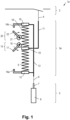
- Fig. 1 shows a first example of an electric switching device 1a, which comprises a switching contact 2, an actuation mechanism 3a coupled to the switching contact 2 via a switch link 4 and a motor 5 coupled to the actuation mechanism 3a via a motor link 6.
- the switching contact 2, the switch link 4, the motor 5 and the motor link 6 are just symbolically depicted in Fig. 1 and may be embodied in different variants. It should also be noted that although Fig. 1 just shows one switching contact 2, the actuation mechanism 3a can also move more than one switching contact 2 simultaneously.
- the motor 5 can be embodied as a linear motor (e.g. as a pneumatic cylinder, hydraulic cylinder or as a spindle motor) or also as a rotational motor (e.g. with a crank or a lever mounted to the motor shaft).
- the motor 5 comprises a piston 7 movably arranged in a cylinder 8.
- a spindle motor can also be seen as a rotational motor.
- the motor link 6 can be embodied as a simple rod but also can comprise a more sophisticated mechanism with rotational and/or translatory moving parts.
- the switching contact 2 is just drawn as an electric symbol but may comprise a sophisticated mechanism and also a vacuum chamber for example.
- the switching contact 2 may be designed for low voltage, medium voltage or high voltage.
- the switch link 4 can be embodied as a simple rod but also comprise a more sophisticated mechanism.
- the actuation mechanism 1 comprises a first spring 9, a first actuation plate 10, which is connected to or contacts the first spring 9 and which is coupled with the switching contact 2, here by means of a switch push rod 11 and the switch link 4. Furthermore, the actuation mechanism 1 comprises a second actuation plate 12, which is connected to or contacts the first spring 9 and which is coupled with the motor 5, here by means of a motor push rod 13 and the motor link 6. The second actuation plate 12 is spaced from the first actuation plate 10 with the first spring 9 in-between and has an optional first actuating element 14a.
- the actuation mechanism 1 comprises a first blocking element 15, which comprises a rotatable first flattened shaft 16 (also called as "D-shaft") and a first lever 17 connected to the first flattened shaft 16.
- the first blocking element 15 is designed to block the first actuation plate 10 in a rotational blocking position and to release the first actuation plate 10 in a rotational release position.
- the first blocking element 15 is shown in its blocking position.
- the actuation mechanism 1 comprises an optional second spring 18 and a third actuation plate 19, which is connected to or which contacts the second spring 18 and which is coupled with the motor 5, again by means of the motor push rod 13 and the motor link 6.
- the third actuation plate 19 is spaced from the first actuation plate 10 with the second spring in-between 17 and has an optional second actuating element 14b.
- the third actuation plate 19 is arranged vis-à-vis of the second actuation plate 12 in view of the first actuation plate 10.
- the actuation mechanism 1 comprises an optional second blocking element 20, which comprises a rotatable second flattened shaft 21 and a second lever 22 connected to the second flattened shaft 21.
- the second blocking element 20 is designed to block the first actuation plate 10 in a rotational blocking position and to release the first actuation plate 10 in a rotational release position.
- the second blocking element 20 is shown in its blocking position, too.
- both the first spring 9 and the second spring 19 are embodied as longitudinal springs, in particular as a helical springs.
- other springs can be used as well.
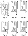
- Figs. 2a to 2f illustrate the function of the actuation mechanism 3a', which is very similar to the actuation mechanism 3a of Fig. 1 and which comprises an optional first stop 23 and an optional second stop 24.
- the embodiment shown in Figs. 2a to 2f comprises a single actuating element 14, however, with the same function.
- Fig. 2a shows the electric switching device 1a in an idle state as illustrated by the pause symbol.
- Fig. 2b the motor 5 starts to move as illustrated by the play symbol. Accordingly, the second actuation plate 12 and the third actuation plate 19 are moved in a first upward direction. As a consequence, the first spring 9 and the second spring 18 are loaded upon movement of the second actuation plate 12 and the third actuation plate 19 in the upward first direction D1. In detail, the first spring 9 is compressed and the second spring 18 is tensioned. The first actuation plate 10 is still blocked by the first blocking element 15 so that the switch push rod 11 does not move as it is illustrated by the stop symbol. As can be seen, the actuating element 14 has reached the first blocking element 15 in Fig. 2b but it has not yet turned it. In more detail, the actuating element 14 contacts the first lever 17 of the first blocking element 15 (see Fig. 1 for details of the first blocking element 15).
- the first actuation plate 10 is going to pass the first flattened shaft 16 and continues to move as is illustrated by an arrow next to the switch push rod 11. Additionally, the motor push rod 13 is still moved by the motor 5.
- the second actuation plate 12 and the third actuation plate 19 have reached their end positions after the actuating element 14 has reached the first stop 23.
- the motor 5 is switched off in this position, for example by means of a first end switch or by detecting an overload caused by the hindered movement. Accordingly, the movement of the motor push rod 13 stops as is illustrated by the stop symbol.
- the first actuation plate 10 still moves and is going to pass the second flattened shaft 21 after it has pushed the second flattened shaft 21 out of its moving path. Strictly speaking, the second blocking element 20 is turned into its release position by the moving first actuation plate 10.
- Fig. 2f the first actuation plate 10 has reached its end position as it is illustrated by means of the stop symbol.
- the switch push rod 11 via the switch link 4 transfers the switching contact 2 into a first switching state, which in this example is the open state.
- the second blocking element 20 has moved back to its blocking position driven by the second return spring (not shown).
- the first (open) switching state and the second (closed) switching state are inversely associated to the position of the switch push rod 11. That means that in Fig. 1 the upper position of the switch push rod 11 is associated with the second (closed) switching state, whereas in Figs. 2a to 2f and the following Figs. 3a to 6f the upper position of the switch push rod 11 is associated with first (open) switching state and vice versa.
- Fig. 2f also shows a second idle state, in which the position of the parts of the actuation mechanism 3a' are basically mirror inverted in view of the state depicted in Fig. 2a .
- Fig. 2a strictly speaking shows a state in which the motor push rod 13 has already been moved upwards a bit and has already left said mirror inverted position. Because of this symmetry, switching on the switching contact 2 just happens like illustrated by Figs. 2a to 2f but with changed roles of the parts and inverted moving directions.
- the second actuation plate 12 and third actuation plate 19 then move in a downward, second direction D2 opposite to the first direction D1 by the motor 5, wherein the first spring 9 and the second spring 18 upon movement of the second actuation plate 12 and the third actuation plate 19 in the second direction D2 are loaded.
- the first spring 9 is tensioned and the second spring 18 is compressed now.
- the actuating element 14 contacts the second lever 22 and upon further movement turns the rotatable second flattened shaft 21.
- the first actuation plate 10 is released and in turn is moved by a release of the loaded first spring 9 and second spring 18. As a consequence the switching contact is transferred into a second switching state, which in this example is the closed state.
- Figs. 3a to 3f now illustrate an embodiment of an actuation mechanism 3b, which is similar to the actuation mechanisms 3a, 3a' of Figs. 1 and 2a to 2f .
- Fig. 3a relates to Fig. 2a , Fig. 3b to Fig. 3b and so forth.
- the actuation mechanism 3b comprises just a first spring 9 and no third actuation plate 19.
- the function of the actuation mechanism 3b is very similar to that of actuation mechanisms 3a, 3a' and almost equals the function of the actuation mechanisms 3a, 3a'.
- the only difference is the missing effect of the non-existing second spring 18 and the missing effect of the non-existing third actuation plate 19.
- Figs. 4a to 4f illustrate an embodiment of an actuation mechanism 3c, which is similar to the actuation mechanisms 3a, 3a' of Figs. 1 and 2a to 2f , too.
- Fig. 4a relates to Fig. 2a , Fig. 4b to Fig. 2b and so forth.
- the switch push rod 11 is not fixedly be mounted to the first actuation plate 10, but in principle it may freely move between the first actuation plate 10 fixed to the first spring 9 and a fourth actuation plate 25 fixed to the second spring 18.
- the function of the actuation mechanism 3c is very similar to that of actuation mechanisms 3a, 3a' and almost equals the function of the actuation mechanisms 3a, 3a'.
- the first actuation plate 10 and the fourth actuation plate 25 can only push the switch push rod 11 (and not pull it like the first actuation plate 10 of actuation mechanisms 3a, 3a' does) and that accordingly there is no tension of the first spring 9 and second spring 18.
- the position of the switch push rod 11 is not linked to the position of the first actuation plate 10 (like this is the case in the actuation mechanisms 3a, 3a') but linked to the position first actuation plate 10 or to the fourth actuation plate 25.
- Figs. 5a to 5f illustrate an embodiment of an actuation mechanism 3d, which is similar to the actuation mechanisms 3a, 3a' of Figs. 1 and 2a to 2f again.
- Fig. 5a relates to Fig. 2a , Fig. 5b to Fig. 2b and so forth.
- the actuation mechanism 3d does not comprise a second blocking element 20 but just a first blocking element 15.
- the actuating elements 14a, 14b are different.
- the actuation mechanism 3d has a first actuating element 14a', which comprises a first actuating element base 26a, a first actuating element spring 27a connected to the first actuating element base 26a and a first actuating element pusher 28a connected to the first actuating element spring 27a.
- the actuation mechanism 3d has a second actuating element 14b', which comprises a second actuating element base 26b, a second actuating element spring 27b connected to the second actuating element base 26b and a second actuating element pusher 28b connected to the second actuating element spring 27b.
- the function of the actuation mechanism 3d again is similar to that of actuation mechanisms 3a, 3a'.
- the first blocking element 15 blocks the movement of the first actuation plate 10 both in the upward first direction D1 and in the downward second direction D2 until it is turned by the first actuating element 14a' or second actuating element 14b'.
- the movement of the motor push rod 13 is not stopped when the first actuating element 14a reaches the first stop 23 or when the second actuating element 14b reaches the second stop 24 but when the first actuating element 14a' (strictly speaking its first actuating element base 26a) or the second actuating element 14b' (strictly speaking its second actuating element base 26b) reaches the first flattened shaft 16 of the first blocking element 15.
- the motor 5 is switched off, for example by means of end switches or by detecting an overload caused by the hindered movement.
- first actuating element spring 27a and the second actuating element spring 27b are designed in a way that the first blocking element 15 can be turned without considerable compression of the first actuating element spring 27a and the second actuating element spring 27b. Accordingly, the first blocking element 15 starts to rotate in Fig. 5b and continues to rotate until the position depicted in Fig. 5c .
- the first actuation plate 10 Because the first blocking element 15 releases the first actuation plate 10, the first actuation plate 10 starts to move upwards and hinders a further rotation of the first blocking element 15 until the first actuation plate 10 has passed the same.
- This blocking situation is depicted in Fig. 5d .
- the elastic first actuating element 14a' and the elastic second actuating element 14b' are provided.
- the first actuating element spring 27a has been compressed, or in other words the first actuating element base 26a has been moved by the motor 5, whereas the first actuating element pusher 28a has not moved.
- Figs. 6a to 6f illustrate an embodiment of an actuation mechanism 3e, which is similar to the actuation mechanisms 3d of Figs. 5a to 5f .
- Fig. 6a relates to Fig. 5a , Fig. 6b to Fig. 5b and so forth.
- the actuation mechanism 3e has rigid actuating elements 14a, 14b again like the actuation mechanism 3a of Fig. 1 has.
- actuation mechanism 3e comprises a micro switch 29, a motor line 30 leading to the motor 5 and an actuation bump 31.
- a blocking situation in Fig. 6d is taken into consideration, where the first blocking element 15 cannot be turned further by the motor 5.
- the motor 5 does not continue to move but is temporarily switched off by the micro switch 29.
- the actuation bump 31 acts on the micro switch 29 in this state.
- the micro switch 29 can be embodied as opener and can be arranged between the motor 5 and a power unit for the motor 5.
- the motor line 30 can also be a control line leading to a control for the motor 5.
- the elastic actuating elements 14a', 14b' of Figs. 5a to 5f and/or the micro switch 29 of Figs. 6a to 6f can be applied to the actuation mechanisms 3a..3c of Figs. 1 to 4f in an equivalent way because similarly said blocking situation can be taken into consideration there.
- the first blocking element 15 may simply be denoted as "blocking element 15" in the embodiments of Figs. 5a to 5f and 6a to 6f because there is just one in these embodiments.
- Fig. 1 , Figs. 2a .. 2f and Figs. 4a .. 6f are symmetric with respect to the springs 9 and 18.
- this is no necessary condition and the springs 9 and 18 may be embodied differently, in particular in view of their length and/or spring constant. Accordingly, switching on and off can take place differently in alternative embodiments.
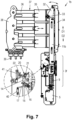
- Fig. 7 now shows a more detailed example of an electric switching device 1b, which comprises an actuating mechanism 3f of the type shown in Fig. 1 and Figs. 2a..2f , however with a differently shaped push rod 11b.
- the push rod 11b is coupled to a pivoted lever 32, which is pivotally mounted in a frame (not shown in Fig. 7 ) by use of a bearing 33 in this embodiment.
- a switching frame 34 is connected to the lever 32, too.
- the switching frame 34 is also connected to a number of switching caps 35, which can be moved on a switch base 36 simultaneously (here in horizontal direction).
- the switching caps 35 and the switch bases 36 are parts of a number of switches 37, which are mounted to a common frame 38.
- Fig. 7 also shows terminals 39 for connecting the electric switching device 1b to a grid.
- each switch base 36 there is a fixed contact, and in each switching cap 35 there is a movable contact.
- the switching frame 34 together with the switching caps 35 is moved from the right to the left thus closing the switching contacts 2.
- the switching frame 34 together with the switching caps 35 is moved from the left to the right thus opening the switching contacts 2.
- the electric switching device 1b can be embodied as three-phase switching device.
- Fig. 7 in addition shows a detailed view of the trigger mechanism comprising the first blocking element 15 and the second blocking element 20.
- Fig. 7 explicitly depicts a first return spring 40, which forces the first blocking element 15 into its rotational blocking position, and a second return spring 41, which forces the second blocking element 20 into its rotational blocking position.
- the actuation mechanism 3f is very slim. That is why it is particularly suitable for retrofitting switch arrangements, which are manually operated originally and where space is limited.
- a door of a switch gear (not shown) may be arranged just right of the switching frame 34.
- the actuation mechanism 3f can be arranged right below the switch arrangement, where often space is left in real applications.
- the electric switching device 1a, 1b and the actuation mechanisms 3a..3f may have more or less parts than shown in the figures.
- the description may comprise subject matter of further independent inventions.
Landscapes
- Driving Mechanisms And Operating Circuits Of Arc-Extinguishing High-Tension Switches (AREA)
Abstract
An electric switching device (1a, 1b) is disclosed, which comprises a switching contact (2), an actuation mechanism (3a..3f) coupled to the switching contact (2) and a motor (5) coupled to the actuation mechanism (3a..3f). The actuation mechanism (3a..3f) comprises a first spring (9), a first actuation plate (10) coupled with the switching contact (2) and a second actuation plate (12) coupled with the motor (5). The actuation mechanism (3a..3f) also comprises a first blocking element (15), which blocks the first actuation plate (10) in a rotational blocking position and releases the first actuation plate (10) in a rotational release position. The first spring (9) is loaded by a movement of the motor (5). At some point in time, the second actuation plate (12) or an actuating element (14, 14a..14b') connected thereto turns the first blocking element (15) and thus releases the first actuation plate (10). As a consequence, the first actuation plate (10) starts to move and finally actuates the switching contact (2).
Description
- The invention relates to an electric switching device, which comprises a switching contact (or more switching contacts), an actuation mechanism coupled to the switching contact and a motor coupled to the actuation mechanism.
- An electric switching device of the above kind is generally known in prior art. To move the movable contact of a switching device, an actuation mechanism coupled with a motor can be used. To prevent or at least reduce arcing in case of switching (on or off), the movable contact shall move with a sufficient speed. However, that requires high drive powers and without special measures a high power motor. To obviate the need for high power motors, a motor in such an application is often coupled with an actuation mechanism, which converts a comparably slow movement of the motor into a high speed movement of the switching contact. Often, springs are used for this reason, which are loaded by the motor and at a particular point in time release and more or less instantaneously move the movable contact of the switch. In other words, energy loaded into the springs is released within a short time what means high mechanical power. A number of actuation mechanisms have been proposed, which however often are bulky.
- Accordingly, the object of the invention is the provision of an improved electric switching device, and in particular the provision of an improved actuation mechanism. In particular, a slim actuation mechanism for an electric switching device shall be provided. More particularly, such an actuation mechanism shall be suitable for retrofitting of manually operated switching contacts.
- The object of the invention is solved by an electric switching device of the type disclosed in the opening paragraph, which comprises
- a first spring,
- a first actuation plate connected to or contacting the first spring and coupled with the switching contact,
- a second actuation plate connected to or contacting the first spring and coupled with the motor, wherein the second actuation plate is spaced from the first actuation plate with at least a part of the first spring in-between, and
- a first blocking element, which comprises a rotatable first flattened shaft (also called as "D-shaft") and a first lever connected to the first flattened shaft and which is designed to block the first actuation plate in a rotational blocking position and to release the first actuation plate in a rotational release position,
- wherein the second actuation plate is movable in a first direction by the motor,
- wherein the first spring or said part thereof upon movement of the second actuation plate in the first direction is loaded,
- wherein the second actuation plate or an actuating element connected thereto upon further movement of the second actuation plate in the first direction contacts the first lever,
- wherein the second actuation plate or the actuating element upon further movement of the second actuation plate in the first direction turns the rotatable first flattened shaft from its rotational blocking position in its rotational release position and
- wherein the first flattened shaft upon reaching its release position releases the first actuation plate, which in turn is moved in the first direction by a release of the loaded first spring or said loaded part of the first spring and as a consequence transfers the switching contact into a first switching state (e.g. into the open state).
- A first actuation plate coupled with the switch is held in position by a first blocking element. To initiate a switching operation, the motor moves a second actuation plate thereby loading (e.g. by compressing or tensioning) a first spring arranged between the two actuation plates. At some point in time, the second actuation plate or an actuating element connected thereto turns the first blocking element from a blocking position into a release position and thus releases the first actuation plate. In turn, the first actuation plate forcefully accelerates into a first direction driven by the first spring and as a consequence quickly changes the switching state of the switching contact.
- By use of the above measures, a slim, durable and reliably actuation mechanism is presented, which provides a good conversion of a movement of a slow moving motor into a high speed movement of a movable switching contact. Accordingly, arcing can be prevented or at least reduced in case of switch on or switch off without having the need of high power motors. For example, such electric switching devices can be used for low voltage, medium voltage and high voltage, in particular in combination with vacuum interrupters, and can also be embodied as (hard-) gas based switching devices. The coupling between the actuation mechanism and the switching contact or between the actuation mechanism and the motor may comprise but is not limited to linearly movable rods and rotatable levers and other rotating elements.
- Further advantageous embodiments are disclosed in the claims and in the description as well as in the figures.
- Advantageously, the electric switching device comprises a second blocking element, which comprises a rotatable second flattened shaft and a second lever connected to the second flattened shaft and which is designed to block the first actuation plate in a rotational blocking position and to release the first actuation plate in a rotational release position,
- wherein the second actuation plate is movable in a second direction opposite to the first direction by the motor,
- wherein the first spring upon movement of the second actuation plate in the second direction is loaded,
- wherein the second actuation plate or an actuating element connected thereto upon further movement of the second actuation plate in the second direction contacts the second lever,
- wherein the second actuation plate or the actuating element upon further movement of the second actuation plate in the second direction turns the rotatable second flattened shaft from its blocking position in its release position and
- wherein the second flattened shaft upon reaching its release position releases the first actuation plate which in turn is moved in the second direction by a release of the loaded first spring and as a consequence transfers the switching contact into a second switching state (e.g. into a closed state).
- In this embodiment, a second blocking element hinders a movement of the first actuation plate in a second direction opposite to the first direction. At some point in time, the second actuation plate or an actuating element connected thereto turns the second blocking element from a blocking position into a release position and thus releases the first actuation plate. In turn, the first actuation plate forcefully accelerates into the second direction driven by the first spring and as a consequence quickly changes the switching state of the switching contact. The second blocking element may provide more design freedom when designing the actuation mechanism.
- In yet another advantageous embodiment, the electric switching device comprises
- a second spring,
- a third actuation plate connected to or contacting the second spring and coupled with the motor, wherein the third actuation plate is spaced from the first actuation plate with the second spring in-between, and
- wherein the third actuation plate is movable in a second direction opposite to the first direction by the motor,
- wherein the second spring upon movement of the third actuation plate in the second direction is loaded and
- -) the third actuation plate or an actuating element connected thereto upon further movement of the third actuation plate in the second direction contacts the first lever,
- -) the third actuation plate or the actuating element upon further movement of the third actuation plate in the second direction turns the rotatable first flattened shaft from its blocking position in its release position and
- -) the first flattened shaft upon reaching its release position releases the first actuation plate which in turn is moved in the second direction by a release of the loaded second spring and as a consequence transfers the switching contact into a second switching state (e.g. closed state) or
- -) the electric switching device comprises a second blocking element, which comprises a rotatable second flattened shaft and a second lever connected to the second flattened shaft and which is designed to block the first actuation plate in a rotational blocking position and to release the first actuation plate in a rotational release position,
- -) the third actuation plate or an actuating element connected thereto upon further movement of the third actuation plate in the second direction contacts the second lever,
- -) the third actuation plate or the actuating element upon further movement of the third actuation plate in the second direction turns the rotatable second flattened shaft from its blocking position in its release position and
- -) the second flattened shaft upon reaching its release position releases the first actuation plate which in turn is moved in the second direction by a release of the loaded second spring and as a consequence transfers the switching contact into a second switching state (e.g. closed state).
- In this embodiment, two springs and two actuation plates coupled with the motor are used for the actuation mechanism. In case a) there is just one blocking element, whereas in case b) there are two blocking elements.
- In yet further advantageous embodiment, the electric switching device comprises
- a second spring,
- a third actuation plate connected to or contacting the second spring and coupled with the motor,
- a fourth actuation plate connected to or contacting the second spring and coupled with the switching contact, wherein the third actuation plate is spaced from the fourth actuation plate with the second spring in-between, and
- wherein the third actuation plate is movable in a second direction opposite to the first direction by the motor,
- wherein the second spring upon movement of the third actuation plate in the second direction is loaded,
- -) the third actuation plate or an actuating element connected thereto upon further movement of the third actuation plate in the second direction contacts the first lever,
- -) the third actuation plate or the actuating element upon further movement of the third actuation plate in the second direction turns the rotatable first flattened shaft from its blocking position in its release position and
- -) the first flattened shaft upon reaching its release position releases the fourth actuation plate which in turn is moved in the second direction by a release of the loaded second spring and as a consequence transfers the switching contact into a second switching state (e.g. closed state) or
- -) the electric switching device comprises a second blocking element, which comprises a rotatable second flattened shaft and a second lever connected to the second flattened shaft and which is designed to block the fourth actuation plate in a rotational blocking position and to release the fourth actuation plate in a rotational release position,
- -) wherein the third actuation plate or an actuating element connected thereto upon further movement of the third actuation plate contacts the second lever,
- -) wherein the third actuation plate or the actuating element upon further movement of the third actuation plate in the second direction turns the rotatable second flattened shaft from its blocking position in its release position and
- -) wherein the second flattened shaft upon reaching its release position releases the fourth actuation plate which in turn is moved in the second direction by a release of the loaded second spring and as a consequence transfers the switching contact into a second switching state (e.g. closed state).
- In this embodiment, two springs and two separate actuation plates driving the switching contact are used. In particular, the actuation plates can be provided for transmitting a movement to the switching contact by a pure push function (but not with a pull function).
- Beneficially the first spring and the second spring can be formed by a first part and a second part of a common spring. In this way, just a single spring is needed, wherein the first actuation plate (and eventually the fourth actuation plate) is arranged between said first and second part.
- Generally, the first spring and the second spring or the first part and the second part may differ in their length and/or in their spring constant to handle opening and closing of the switching contact differently. For example, the spring, which is provided for opening the switching contact can be made stronger so as to provide a very fast opening movement. In several cases, depending on the contact type, the closing spring can be made stronger in order to create sufficient contact pressure (e.g. for butt contacts).
- Advantageously, the actuating element can be embodied as an elastic actuating element and in particular can comprise an actuating element base, an actuating element spring connected to the actuating element base and an actuating element pusher. When the first actuation plate passes the first blocking element or second blocking element or when the fourth actuation plate passes the second blocking element, there may be a time period, in which a movement of the blocking elements is hindered by the actuation plates. To allow a continuous movement of the motor during this pass by or transition, the elastic actuating element is provided.
- In another advantageous embodiment, the electric switching device comprises a micro switch, which is designed to interrupt a movement of the motor when the first actuation plate passes the first blocking element or when the fourth actuation plate passes the second blocking element. As stated above, a movement of the blocking elements can be hindered by an actuation plate when the first actuation plate passes the first blocking element or second blocking element or when the fourth actuation plate passes the second blocking element, in this embodiment, the motor does not continue to move but is temporarily switched off by the micro switch. For example, an actuation bump, which is coupled to the first or fourth actuation plate, can act on the micro switch. In principle, the micro switch can be embodied as opener and can be arranged between motor and a power unit. However, the micro switch can also be connected to a motor line, which leads to a control for the motor and switches off the same in this way. Once the first actuation plate has passed the first blocking element, the motor is switched on again and continues to move until its end position.
- In one embodiment, the first spring and/or the second spring can be embodied as a longitudinal spring, in particular as a helical spring. Beneficially, these springs can store energy when they are linearly loaded.
- In another embodiment, the first spring and/or the second spring can be embodied as a compression spring, tension spring or combined compression and tension spring. In particular, if the first spring and/or the second spring is embodied as a combined compression and tension spring, it can be used for both the first and second direction and hence for switching the switching contact into two different switching states.
- In one further embodiment, the motor can be embodied as a linear motor. For example, the motor can be embodied as a pneumatic, hydraulic cylinder or a spindle motor.
- The invention now is described in more detail hereinafter with reference to particular embodiments, which the invention however is not limited to.
- Fig. 1
- shows a schematic side view of a first example of an electric switching device;
- Figs. 2a..2f
- illustrate the function of an actuation mechanism similar to that of
Fig. 1 ; - Figs. 3a..3f
- illustrate the function of an actuation mechanism with a single spring;
- Figs. 4a..4f
- illustrate the function of an actuation mechanism with two separate actuation plates for the switch link;
- Figs. 5a..5f
- illustrate the function of an actuation mechanism with elastic actuating elements;
- Figs. 6a..6f
- illustrate the function of an actuation mechanism with a micro switch for temporarily switching off the motor and
- Fig. 7
- a side view of a more detailed example of an electric switching device.
- Generally, same parts or similar parts are denoted with the same/similar names and reference signs. The features disclosed in the description apply to parts with the same/similar names respectively same/similar reference signs. Indicating the orientation and relative position is related to the associated figure, and indication of the orientation and/or relative position has to be amended in different figures accordingly as the case may be.
-
Fig. 1 shows a first example of anelectric switching device 1a, which comprises aswitching contact 2, anactuation mechanism 3a coupled to theswitching contact 2 via aswitch link 4 and amotor 5 coupled to theactuation mechanism 3a via amotor link 6. Theswitching contact 2, theswitch link 4, themotor 5 and themotor link 6 are just symbolically depicted inFig. 1 and may be embodied in different variants. It should also be noted that althoughFig. 1 just shows oneswitching contact 2, theactuation mechanism 3a can also move more than oneswitching contact 2 simultaneously. - For example, the
motor 5 can be embodied as a linear motor (e.g. as a pneumatic cylinder, hydraulic cylinder or as a spindle motor) or also as a rotational motor (e.g. with a crank or a lever mounted to the motor shaft). InFig. 1 , themotor 5 comprises apiston 7 movably arranged in acylinder 8. In this context it should also be noted that a spindle motor can also be seen as a rotational motor. Themotor link 6 can be embodied as a simple rod but also can comprise a more sophisticated mechanism with rotational and/or translatory moving parts. Similarly, theswitching contact 2 is just drawn as an electric symbol but may comprise a sophisticated mechanism and also a vacuum chamber for example. Theswitching contact 2 may be designed for low voltage, medium voltage or high voltage. Just like themotor link 6, theswitch link 4 can be embodied as a simple rod but also comprise a more sophisticated mechanism. - The actuation mechanism 1 comprises a
first spring 9, afirst actuation plate 10, which is connected to or contacts thefirst spring 9 and which is coupled with theswitching contact 2, here by means of aswitch push rod 11 and theswitch link 4. Furthermore, the actuation mechanism 1 comprises asecond actuation plate 12, which is connected to or contacts thefirst spring 9 and which is coupled with themotor 5, here by means of amotor push rod 13 and themotor link 6. Thesecond actuation plate 12 is spaced from thefirst actuation plate 10 with thefirst spring 9 in-between and has an optionalfirst actuating element 14a. Moreover, the actuation mechanism 1 comprises afirst blocking element 15, which comprises a rotatable first flattened shaft 16 (also called as "D-shaft") and afirst lever 17 connected to the first flattenedshaft 16. Thefirst blocking element 15 is designed to block thefirst actuation plate 10 in a rotational blocking position and to release thefirst actuation plate 10 in a rotational release position. InFig. 1 , thefirst blocking element 15 is shown in its blocking position. There may also be an optional first return spring (not shown inFig. 1 but refer toFig. 7 ), which forces thefirst blocking element 15 into its blocking position as illustrated by means of an arrow inFig. 1 . - In addition, the actuation mechanism 1 comprises an optional
second spring 18 and athird actuation plate 19, which is connected to or which contacts thesecond spring 18 and which is coupled with themotor 5, again by means of themotor push rod 13 and themotor link 6. Thethird actuation plate 19 is spaced from thefirst actuation plate 10 with the second spring in-between 17 and has an optionalsecond actuating element 14b. In fact, thethird actuation plate 19 is arranged vis-à-vis of thesecond actuation plate 12 in view of thefirst actuation plate 10. Moreover, the actuation mechanism 1 comprises an optionalsecond blocking element 20, which comprises a rotatable second flattenedshaft 21 and asecond lever 22 connected to the second flattenedshaft 21. Thesecond blocking element 20 is designed to block thefirst actuation plate 10 in a rotational blocking position and to release thefirst actuation plate 10 in a rotational release position. InFig. 1 , thesecond blocking element 20 is shown in its blocking position, too. There may also be an optional second return spring (not shown inFig. 1 but refer toFig. 7 ), which forces thesecond blocking element 20 into its blocking position as illustrated by means of a further arrow inFig. 1 . - In this embodiment, both the
first spring 9 and thesecond spring 19 are embodied as longitudinal springs, in particular as a helical springs. However, other springs can be used as well. -
Figs. 2a to 2f illustrate the function of theactuation mechanism 3a', which is very similar to theactuation mechanism 3a ofFig. 1 and which comprises an optionalfirst stop 23 and an optionalsecond stop 24. Instead of twoseparate actuating elements Figs. 2a to 2f comprises asingle actuating element 14, however, with the same function.Fig. 2a shows theelectric switching device 1a in an idle state as illustrated by the pause symbol. - In
Fig. 2b , themotor 5 starts to move as illustrated by the play symbol. Accordingly, thesecond actuation plate 12 and thethird actuation plate 19 are moved in a first upward direction. As a consequence, thefirst spring 9 and thesecond spring 18 are loaded upon movement of thesecond actuation plate 12 and thethird actuation plate 19 in the upward first direction D1. In detail, thefirst spring 9 is compressed and thesecond spring 18 is tensioned. Thefirst actuation plate 10 is still blocked by thefirst blocking element 15 so that theswitch push rod 11 does not move as it is illustrated by the stop symbol. As can be seen, theactuating element 14 has reached thefirst blocking element 15 inFig. 2b but it has not yet turned it. In more detail, theactuating element 14 contacts thefirst lever 17 of the first blocking element 15 (seeFig. 1 for details of the first blocking element 15). - In
Fig. 2c , thefirst spring 9 and thesecond spring 18 have been loaded to their maximum upon further movement of themotor 5. As can be seen inFig. 2c , theswitch push rod 11 still does not move as it is illustrated by the stop symbol. However, theactuating element 14 has already turned the rotatable first flattenedshaft 16 or thefirst blocking element 15 respectively from its rotational blocking position in its rotational release position. When the first flattenedshaft 16 reaches its release position, it releases thefirst actuation plate 10 which is the case inFig. 2c . As a consequence, thefirst actuation plate 10 starts to move in the upward, first direction D1 driven by a release of the loadedfirst spring 9 and thesecond spring 18. - In the state depicted in
Fig. 2d , thefirst actuation plate 10 is going to pass the first flattenedshaft 16 and continues to move as is illustrated by an arrow next to theswitch push rod 11. Additionally, themotor push rod 13 is still moved by themotor 5. - In
Fig. 2e , thesecond actuation plate 12 and thethird actuation plate 19 have reached their end positions after theactuating element 14 has reached thefirst stop 23. Themotor 5 is switched off in this position, for example by means of a first end switch or by detecting an overload caused by the hindered movement. Accordingly, the movement of themotor push rod 13 stops as is illustrated by the stop symbol. Thefirst actuation plate 10 still moves and is going to pass the second flattenedshaft 21 after it has pushed the second flattenedshaft 21 out of its moving path. Strictly speaking, thesecond blocking element 20 is turned into its release position by the movingfirst actuation plate 10. - In
Fig. 2f thefirst actuation plate 10 has reached its end position as it is illustrated by means of the stop symbol. By the upward movement, theswitch push rod 11 via theswitch link 4 transfers theswitching contact 2 into a first switching state, which in this example is the open state. Thesecond blocking element 20 has moved back to its blocking position driven by the second return spring (not shown). One should note that inFig. 1 and inFigs. 2a to 2f (and the followingFigs. 3a to 6f ), the first (open) switching state and the second (closed) switching state are inversely associated to the position of theswitch push rod 11. That means that inFig. 1 the upper position of theswitch push rod 11 is associated with the second (closed) switching state, whereas inFigs. 2a to 2f and the followingFigs. 3a to 6f the upper position of theswitch push rod 11 is associated with first (open) switching state and vice versa. -
Fig. 2f also shows a second idle state, in which the position of the parts of theactuation mechanism 3a' are basically mirror inverted in view of the state depicted inFig. 2a . However, one should note for the sake of better understanding,Fig. 2a strictly speaking shows a state in which themotor push rod 13 has already been moved upwards a bit and has already left said mirror inverted position. Because of this symmetry, switching on theswitching contact 2 just happens like illustrated byFigs. 2a to 2f but with changed roles of the parts and inverted moving directions. - In more detail, the
second actuation plate 12 andthird actuation plate 19 then move in a downward, second direction D2 opposite to the first direction D1 by themotor 5, wherein thefirst spring 9 and thesecond spring 18 upon movement of thesecond actuation plate 12 and thethird actuation plate 19 in the second direction D2 are loaded. In detail, thefirst spring 9 is tensioned and thesecond spring 18 is compressed now. Upon further movement of thesecond actuation plate 12 and thethird actuation plate 19, theactuating element 14 contacts thesecond lever 22 and upon further movement turns the rotatable second flattenedshaft 21. When the second flattenedshaft 21 has turned from the blocking position into its release position, thefirst actuation plate 10 is released and in turn is moved by a release of the loadedfirst spring 9 andsecond spring 18. As a consequence the switching contact is transferred into a second switching state, which in this example is the closed state. - By use of the
first spring 9 and thesecond spring 18, switching takes place very fast. -
Figs. 3a to 3f now illustrate an embodiment of anactuation mechanism 3b, which is similar to theactuation mechanisms Figs. 1 and2a to 2f .Fig. 3a relates toFig. 2a ,Fig. 3b to Fig. 3b and so forth. As can be seen, theactuation mechanism 3b comprises just afirst spring 9 and nothird actuation plate 19. Nevertheless, the function of theactuation mechanism 3b is very similar to that ofactuation mechanisms actuation mechanisms second spring 18 and the missing effect of the non-existingthird actuation plate 19. -
Figs. 4a to 4f illustrate an embodiment of anactuation mechanism 3c, which is similar to theactuation mechanisms Figs. 1 and2a to 2f , too.Fig. 4a relates toFig. 2a ,Fig. 4b to Fig. 2b and so forth. As can be seen, theswitch push rod 11 is not fixedly be mounted to thefirst actuation plate 10, but in principle it may freely move between thefirst actuation plate 10 fixed to thefirst spring 9 and a fourth actuation plate 25 fixed to thesecond spring 18. Nevertheless, the function of theactuation mechanism 3c is very similar to that ofactuation mechanisms actuation mechanisms first actuation plate 10 and the fourth actuation plate 25 can only push the switch push rod 11 (and not pull it like thefirst actuation plate 10 ofactuation mechanisms first spring 9 andsecond spring 18. Moreover, the position of theswitch push rod 11 is not linked to the position of the first actuation plate 10 (like this is the case in theactuation mechanisms first actuation plate 10 or to the fourth actuation plate 25. -
Figs. 5a to 5f illustrate an embodiment of anactuation mechanism 3d, which is similar to theactuation mechanisms Figs. 1 and2a to 2f again.Fig. 5a relates toFig. 2a ,Fig. 5b to Fig. 2b and so forth. As can be seen, theactuation mechanism 3d does not comprise asecond blocking element 20 but just afirst blocking element 15. Moreover, theactuating elements actuation mechanism 3d has afirst actuating element 14a', which comprises a firstactuating element base 26a, a firstactuating element spring 27a connected to the firstactuating element base 26a and a firstactuating element pusher 28a connected to the firstactuating element spring 27a. Similarly, theactuation mechanism 3d has asecond actuating element 14b', which comprises a secondactuating element base 26b, a secondactuating element spring 27b connected to the secondactuating element base 26b and a secondactuating element pusher 28b connected to the secondactuating element spring 27b. However, the function of theactuation mechanism 3d again is similar to that ofactuation mechanisms first blocking element 15 blocks the movement of thefirst actuation plate 10 both in the upward first direction D1 and in the downward second direction D2 until it is turned by thefirst actuating element 14a' orsecond actuating element 14b'. One further difference is that the movement of themotor push rod 13 is not stopped when thefirst actuating element 14a reaches thefirst stop 23 or when thesecond actuating element 14b reaches thesecond stop 24 but when thefirst actuating element 14a' (strictly speaking its firstactuating element base 26a) or thesecond actuating element 14b' (strictly speaking its secondactuating element base 26b) reaches the first flattenedshaft 16 of thefirst blocking element 15. In these positions, themotor 5 is switched off, for example by means of end switches or by detecting an overload caused by the hindered movement. - The reason for the provision of the elastic
first actuating element 14a' and the elasticsecond actuating element 14b' is explained by useFigs. 5b to 5f . It should be noted that the firstactuating element spring 27a and the secondactuating element spring 27b (or other equivalent elastic elements) are designed in a way that thefirst blocking element 15 can be turned without considerable compression of the firstactuating element spring 27a and the secondactuating element spring 27b. Accordingly, thefirst blocking element 15 starts to rotate inFig. 5b and continues to rotate until the position depicted inFig. 5c . Because thefirst blocking element 15 releases thefirst actuation plate 10, thefirst actuation plate 10 starts to move upwards and hinders a further rotation of thefirst blocking element 15 until thefirst actuation plate 10 has passed the same. This blocking situation is depicted inFig. 5d . However, to (better) allow a continuous movement of themotor 5 during this pass by or transition, the elasticfirst actuating element 14a' and the elasticsecond actuating element 14b' are provided. As can be seen inFig. 5d , the firstactuating element spring 27a has been compressed, or in other words the firstactuating element base 26a has been moved by themotor 5, whereas the firstactuating element pusher 28a has not moved. After thefirst actuation plate 10 has passed thefirst blocking element 15, the firstactuating element spring 27a relaxes again. This situation is depicted inFig. 5e . InFig. 5f , themotor push rod 13 has reached its end position. When themotor 5 moves themotor push rod 13 downward in the second direction D2, things are just the other way around. -
Figs. 6a to 6f illustrate an embodiment of anactuation mechanism 3e, which is similar to theactuation mechanisms 3d ofFigs. 5a to 5f .Fig. 6a relates toFig. 5a ,Fig. 6b to Fig. 5b and so forth. In contrast, theactuation mechanism 3e hasrigid actuating elements actuation mechanism 3a ofFig. 1 has. A further difference is thatactuation mechanism 3e comprises amicro switch 29, amotor line 30 leading to themotor 5 and anactuation bump 31. Like inFig. 5d , a blocking situation inFig. 6d is taken into consideration, where thefirst blocking element 15 cannot be turned further by themotor 5. However, in this embodiment, themotor 5 does not continue to move but is temporarily switched off by themicro switch 29. As can be seen inFig. 6d , theactuation bump 31 acts on themicro switch 29 in this state. In principle, themicro switch 29 can be embodied as opener and can be arranged between themotor 5 and a power unit for themotor 5. However, themotor line 30 can also be a control line leading to a control for themotor 5. Once thefirst actuation plate 10 has passed thefirst blocking element 15, themotor 5 is switched on again as depicted inFig. 6e and continues to move until its end position depicted inFig. 6f . - It should be noted that the
elastic actuating elements 14a', 14b' ofFigs. 5a to 5f and/or themicro switch 29 ofFigs. 6a to 6f can be applied to theactuation mechanisms 3a..3c ofFigs. 1 to 4f in an equivalent way because similarly said blocking situation can be taken into consideration there. It should also be noted that thefirst blocking element 15 may simply be denoted as "blockingelement 15" in the embodiments ofFigs. 5a to 5f and6a to 6f because there is just one in these embodiments. - Furthermore, one should note that the embodiments of
Fig. 1 ,Figs. 2a ..2f andFigs. 4a ..6f are symmetric with respect to thesprings springs -
Fig. 7 now shows a more detailed example of anelectric switching device 1b, which comprises anactuating mechanism 3f of the type shown inFig. 1 andFigs. 2a..2f , however with a differently shapedpush rod 11b. Thepush rod 11b is coupled to a pivotedlever 32, which is pivotally mounted in a frame (not shown inFig. 7 ) by use of abearing 33 in this embodiment. A switchingframe 34 is connected to thelever 32, too. The switchingframe 34 is also connected to a number of switching caps 35, which can be moved on aswitch base 36 simultaneously (here in horizontal direction). The switching caps 35 and the switch bases 36 are parts of a number ofswitches 37, which are mounted to acommon frame 38.Fig. 7 also showsterminals 39 for connecting theelectric switching device 1b to a grid. - In each
switch base 36 there is a fixed contact, and in each switchingcap 35 there is a movable contact. When thepush rod 11b is moved upwards in the first direction D1, the switchingframe 34 together with the switching caps 35 is moved from the right to the left thus closing the switchingcontacts 2. When thepush rod 11b is moved downwards in the second direction D2, the switchingframe 34 together with the switching caps 35 is moved from the left to the right thus opening the switchingcontacts 2. For example, theelectric switching device 1b can be embodied as three-phase switching device. - In the lower left corner,
Fig. 7 in addition shows a detailed view of the trigger mechanism comprising thefirst blocking element 15 and thesecond blocking element 20. In addition to the parts already known fromFig. 1 ,Fig. 7 explicitly depicts afirst return spring 40, which forces thefirst blocking element 15 into its rotational blocking position, and asecond return spring 41, which forces thesecond blocking element 20 into its rotational blocking position. - As can be realized from
Fig. 7 theactuation mechanism 3f is very slim. That is why it is particularly suitable for retrofitting switch arrangements, which are manually operated originally and where space is limited. In a real application of theelectric switching device 1b ofFig. 7 , a door of a switch gear (not shown) may be arranged just right of the switchingframe 34. By use of the pivotedlever 32, theactuation mechanism 3f can be arranged right below the switch arrangement, where often space is left in real applications. - In reality, the
electric switching device actuation mechanisms 3a..3f may have more or less parts than shown in the figures. Moreover, the description may comprise subject matter of further independent inventions. - It should also be noted that the term "comprising" does not exclude other elements and the use of articles "a" or "an" does not exclude a plurality. Also elements described in association with different embodiments may be combined. It should also be noted that reference signs in the claims should not be construed as limiting the scope of the claims.
-
- 1a, 1b
- electric switching device
- 2
- switching contact
- 3a..3f
- actuation mechanism
- 4
- switch link
- 5
- motor
- 6
- motor link
- 7
- piston
- 8
- cylinder
- 9
- first spring
- 10
- first actuation plate
- 11
- switch push rod
- 12
- second actuation plate
- 13
- motor push rod
- 14, 14a..14b'
- actuating element
- 15
- first blocking element
- 16
- first flattened shaft
- 17
- first lever
- 18
- second spring
- 19
- third actuation plate
- 20
- second blocking element
- 21
- second flattened shaft
- 22
- second lever
- 23
- first stop
- 24
- second stop
- 25
- fourth actuation plate
- 26a, 26b
- actuating element base
- 27a, 27b
- actuating element spring
- 28a, 28b
- actuating element pusher
- 29
- micro switch
- 30
- motor line
- 31
- actuation bump
- 32
- pivoted lever
- 33
- bearing
- 34
- switching frame
- 35
- switching cap
- 36
- switch base
- 37
- switch
- 38
- common frame
- 39
- terminal
- 40
- first return spring
- 41
- second return spring
- D1
- first direction
- D2
- second direction
Claims (10)
- Electric switching device (1a, 1b), comprising- a switching contact (2),- an actuation mechanism (3a..3f) coupled to the switching contact (2) and- a motor (5) coupled to the actuation mechanism (3a..3f),
characterized in that
the actuation mechanism (3a..3f) comprises- a first spring (9),- a first actuation plate (10) connected to or contacting the first spring (9) and coupled with the switching contact (2),- a second actuation plate (12) connected to or contacting the first spring (9) and coupled with the motor (5), wherein the second actuation plate (12) is spaced from the first actuation plate (10) with at least a part of the first spring (9) in-between, and- a first blocking element (15), which comprises a rotatable first flattened shaft (16) and a first lever (17) connected to the first flattened shaft (16) and which is designed to block the first actuation plate (10) in a rotational blocking position and to release the first actuation plate (10) in a rotational release position,- wherein the second actuation plate (12) is movable in a first direction (D1) by the motor (5),- wherein the first spring (9) or said part thereof upon movement of the second actuation plate (12) in the first direction (D1) is loaded,- wherein the second actuation plate (12) or an actuating
element (14, 14a..14b') connected thereto upon further movement of the second actuation plate (12) in the first direction (D1) contacts the first lever (17),- wherein the second actuation plate (12) or the actuating
element (14, 14a..14b') upon further movement of the second actuation plate (12) in the first direction (D1) turns the rotatable first flattened shaft (16) from its rotational blocking position into its rotational release position and- wherein the first flattened shaft (16) upon reaching its release position releases the first actuation plate (10), which in turn is moved in the first direction (D1) by a release of the loaded first spring (9) or said loaded part of the first spring (9) and as a consequence transfers the switching contact (2) into a first switching state. - Electric switching device (1a, 1b) as claimed in claim 1, characterized in that- the electric switching device (1a, 1b) comprises a second blocking element (20), which comprises a rotatable second flattened shaft (21) and a second lever (22) connected to the second flattened shaft (21) and which is designed to block the first actuation plate (10) in a rotational blocking position and to release the first actuation plate in a rotational release position,- wherein the second actuation plate (12) is movable in a second direction (D2) opposite to the first direction (D1) by the motor (5),- wherein the first spring (9) upon movement of the second actuation plate (12) in the second direction (D2) is loaded,- wherein the second actuation plate (12) or an actuating
element (14, 14a..14b') connected thereto upon further movement of the second actuation plate (12) in the second direction (D2) contacts the second lever (22),- wherein the second actuation plate (12) or the actuating element (14, 14a..14b') upon further movement of the second actuation plate (12) in the second direction (D2) turns the rotatable second flattened shaft (21) from its blocking position into its release position and- wherein the second flattened shaft (21) upon reaching its release position releases the first actuation plate (10) which in turn is moved in the second direction (D2) by a release of the loaded first spring (9) and as a consequence transfers the switching contact (2) into a second switching state. - Electric switching device (1a, 1b) as claimed in claim 1, characterized in that the electric switching device (1a, 1b) comprises- a second spring (18),- a third actuation plate (19) connected to or contacting the second spring (18) and coupled with the motor (5), wherein the third actuation plate (19) is spaced from the first actuation plate (10) with the second spring (18) in-between, and- wherein the third actuation plate (19) is movable in a second direction (D2) opposite to the first direction (D1) by the motor (5),- wherein the second spring (18) upon movement of the third actuation plate (19) in the second direction (D2) is loaded andwherein in a case a)-) the third actuation plate (19) or an actuating element (14, 14a..14b') connected thereto upon further movement of the third actuation plate (19) in the second direction (D2) contacts the first lever (17),-) the third actuation plate (19) or the actuating element (14, 14a..14b') upon further movement of the third actuation plate (19) in the second direction (D2) turns the rotatable first flattened shaft (16) from its blocking position in its release position and-) the first flattened shaft (16) upon reaching its release position releases the first actuation plate (10) which in turn is moved in the second direction (D2) by a release of the loaded second spring (18) and as a consequence transfers the switching contact (2) into a second switching state orwherein in a case b)-) the electric switching device (1a, 1b) comprises a second blocking element (20), which comprises a rotatable second flattened shaft (21) and a second lever (22) connected to the second flattened shaft (21) and which is designed to block the first actuation plate (10) in a rotational blocking position and to release the first actuation plate (10) in a rotational release position,-) the third actuation plate (19) or an actuating element (14, 14a..14b') connected thereto upon further movement of the third actuation plate (19) in the second direction (D2) contacts the second lever (22),-) the third actuation plate (19) or the actuating element (14, 14a..14b') upon further movement of the third actuation plate (19) in the second direction (D2) turns the rotatable second flattened shaft (21) from its blocking position in its release position and-) the second flattened shaft (21) upon reaching its release position releases the first actuation plate (10) which in turn is moved in the second direction (D2) by a release of the loaded second spring (18) and as a consequence transfers the switching contact (2) into a second switching state.
- Electric switching device (1a, 1b) as claimed in claim 1, characterized in that the electric switching device (1a, 1b) comprises- a second spring (18),- a third actuation plate (19) connected to or contacting the second spring (18) and coupled with the motor (5),- a fourth actuation plate (25) connected to or contacting the second spring (18) and coupled with the switching contact (2), wherein the third actuation plate (18) is spaced from the fourth actuation plate (25) with the second spring (18) in-between, and- wherein the third actuation plate (19) is movable in a second direction (D2) opposite to the first direction (D1) by the motor (5),- wherein the second spring (18) upon movement of the third actuation plate (19) in the second direction (D2) is loaded,wherein in a case a)-) the third actuation plate (19) or an actuating element (14, 14a..14b') connected thereto upon further movement of the third actuation plate (19) in the second direction (D2) contacts the first lever (17),-) the third actuation plate (19) or the actuating element (14, 14a..14b') upon further movement of the third actuation plate (19) in the second direction (D2) turns the rotatable first flattened shaft (16) from its blocking position into its release position and-) the first flattened shaft (16) upon reaching its release position releases the fourth actuation plate (25) which in turn is moved in the second direction (D2) by a release of the loaded second spring (18) and as a consequence transfers the switching contact (2) into a second switching state orwherein in a case b)-) the electric switching device (1a, 1b) comprises a second blocking element (20), which comprises a rotatable second flattened shaft (21) and a second lever (22) connected to the second flattened shaft (21) and which is designed to block the fourth actuation plate (25) in a rotational blocking position and to release the fourth actuation plate (25) in a rotational release position,-) wherein the third actuation plate (19) or an actuating element (14, 14a..14b') connected thereto upon further movement of the third actuation plate (19 in the second direction (D2) contacts the second lever (22),-) wherein the third actuation plate (19) or the actuating element (14, 14a..14b') upon further movement of the third actuation plate (19) in the second direction (D2) turns the rotatable second flattened shaft (21) from its blocking position into its release position and-) wherein the second flattened shaft (21) upon reaching its release position releases the fourth actuation plate (25) which in turn is moved in the second direction (D2) by a release of the loaded second spring (18) and as a consequence transfers the switching contact (2) into a second switching state.
- Electric switching device (1a, 1b) as claimed in claim 3 or 4, characterized in that the first spring (9) and the second spring (18) are formed by a first part and a second part of a common spring.
- Electric switching device (1a, 1b) as claimed in any one of claims 1 to 5, characterized in that the actuating element (14, 14a..14b') is embodied as an elastic actuating element (14, 14a..14b').
- Electric switching device (1a, 1b) as claimed in any one of claims 1 to 6, characterized in a micro switch (28), which is designed to interrupt a movement of the motor (5) when the first actuation plate (10) passes the first blocking element (15) or when the fourth actuation plate (25) passes the second blocking element (20).
- Electric switching device (1a, 1b) as claimed in any one of claims 1 to 7, characterized in that the first spring (9) and/or the second spring (18) is embodied as a longitudinal spring.
- Electric switching device (1a, 1b) as claimed in any one of claims 1 to 8, characterized in that the first spring (9) and/or the second spring (18) is embodied as a compression spring, tension spring or combined compression and tension spring.
- Electric switching device (1a, 1b) as claimed in any one of claims 1 to 9, characterized in that the motor (5) is embodied as a linear motor.
Applications Claiming Priority (1)
| Application Number | Priority Date | Filing Date | Title |
|---|---|---|---|
| GB2303834.2A GB2628148A (en) | 2023-03-16 | 2023-03-16 | Electric switching device with improved actuation mechanism |
Publications (1)
| Publication Number | Publication Date |
|---|---|
| EP4443458A1 true EP4443458A1 (en) | 2024-10-09 |
Family
ID=90365459
Family Applications (1)
| Application Number | Title | Priority Date | Filing Date |
|---|---|---|---|
| EP24163578.8A Withdrawn EP4443458A1 (en) | 2023-03-16 | 2024-03-14 | Electric switching device with improved actuation mechanism |
Country Status (3)
| Country | Link |
|---|---|
| US (1) | US20240312751A1 (en) |
| EP (1) | EP4443458A1 (en) |
| GB (1) | GB2628148A (en) |
Citations (4)
| Publication number | Priority date | Publication date | Assignee | Title |
|---|---|---|---|---|
| DE915361C (en) * | 1940-07-26 | 1954-07-19 | Siemens Ag | Drive with energy storage, especially for high-speed switches |
| GB1044620A (en) * | 1963-06-24 | 1966-10-05 | Ite Circuit Breaker Ltd | Spring operator means |
| US5006682A (en) * | 1989-05-24 | 1991-04-09 | Westinghouse Electric Corp. | Linear snap action operating mechanism and an electrical switch incorporating same |
| WO2017050561A1 (en) * | 2015-09-25 | 2017-03-30 | Siemens Aktiengesellschaft | Drive and method for driving a power switch |
Family Cites Families (5)
| Publication number | Priority date | Publication date | Assignee | Title |
|---|---|---|---|---|
| DE913665C (en) * | 1940-07-26 | 1954-06-18 | Siemens Ag | Spring drive, especially for electrical switches |
| FR2512584A1 (en) * | 1981-09-09 | 1983-03-11 | Petercem Sa | Automatic or manual contactor-circuit breaker - uses slider, carrying main contactor contacts, mechanically coupled to circuit breaker contacts to open contactor |
| FR2640424A1 (en) * | 1988-12-09 | 1990-06-15 | Alsthom Gec | CIRCUIT BREAKER CONTROL |
| US8203088B2 (en) * | 2010-03-31 | 2012-06-19 | Eaton Corporation | Electrical switching apparatus and close latch interlock assembly therefor |
| GB202105357D0 (en) * | 2021-04-15 | 2021-06-02 | Eaton Intelligent Power Ltd | Operating mechanism for a switch |
-
2023
- 2023-03-16 GB GB2303834.2A patent/GB2628148A/en active Pending
-
2024
- 2024-03-14 US US18/604,953 patent/US20240312751A1/en active Pending
- 2024-03-14 EP EP24163578.8A patent/EP4443458A1/en not_active Withdrawn
Patent Citations (4)
| Publication number | Priority date | Publication date | Assignee | Title |
|---|---|---|---|---|
| DE915361C (en) * | 1940-07-26 | 1954-07-19 | Siemens Ag | Drive with energy storage, especially for high-speed switches |
| GB1044620A (en) * | 1963-06-24 | 1966-10-05 | Ite Circuit Breaker Ltd | Spring operator means |
| US5006682A (en) * | 1989-05-24 | 1991-04-09 | Westinghouse Electric Corp. | Linear snap action operating mechanism and an electrical switch incorporating same |
| WO2017050561A1 (en) * | 2015-09-25 | 2017-03-30 | Siemens Aktiengesellschaft | Drive and method for driving a power switch |
Also Published As
| Publication number | Publication date |
|---|---|
| GB2628148A (en) | 2024-09-18 |
| US20240312751A1 (en) | 2024-09-19 |
Similar Documents
| Publication | Publication Date | Title |
|---|---|---|
| JP3861832B2 (en) | Switch | |
| CN1052330C (en) | A circuit breaker mechanism equipped with an energy storage device with a damping stop | |
| KR20140112503A (en) | Mobile conducting unit for a breaker, including a spring for accelerating the separation of arc contacts | |
| US6232569B1 (en) | Switch control device | |
| EP4026154B1 (en) | Semi-independent switch-disconnector | |
| JP2010526974A (en) | valve | |
| WO2008043665A1 (en) | Switching device for electric power system | |
| GB2129617A (en) | Electrical isolating switch | |
| US20240312751A1 (en) | Electric switching device with improved actuation mechanism | |
| EP2172957A2 (en) | A compact circuit breaker mechanism. | |
| KR101899308B1 (en) | Modular moc driver and interlock assembly for circuit breaker | |
| CN218826694U (en) | Actuating mechanism for switchgear and switchgear | |
| EP0924728B1 (en) | High-voltage circuit breaker for high currents | |
| CN1062378C (en) | Medium voltage switch or circuit breaker | |
| CN213937772U (en) | High-voltage motor comprehensive starter | |
| EP2768006B1 (en) | Fast switching-on mechanism | |
| US3852553A (en) | Vacuum switch with toggle assembly operating mechanism | |
| US7672108B2 (en) | Fault interrupter and disconnect device | |
| KR200377715Y1 (en) | A Connecting Device Between Cubicle Type SF6 Gas Insulated Switchgear And Vacuum Interupter | |
| EP0521585B1 (en) | An improved drive mechanism for an electric switch, in particular a circuit breaker or power switch | |
| CN112511038B (en) | A high voltage motor integrated starter | |
| CN116504575B (en) | Outdoor intelligent switch with multiple sequential conduction isolating switches | |
| SU1210152A1 (en) | Vacuum circuit breaker | |
| JP2517179B2 (en) | Switching switch operation mechanism | |
| JP3446336B2 (en) | Energy-saving quick-disconnect device for tap changer under load |
Legal Events
| Date | Code | Title | Description |
|---|---|---|---|
| PUAI | Public reference made under article 153(3) epc to a published international application that has entered the european phase |
Free format text: ORIGINAL CODE: 0009012 |
|
| STAA | Information on the status of an ep patent application or granted ep patent |
Free format text: STATUS: THE APPLICATION HAS BEEN PUBLISHED |
|
| AK | Designated contracting states |
Kind code of ref document: A1 Designated state(s): AL AT BE BG CH CY CZ DE DK EE ES FI FR GB GR HR HU IE IS IT LI LT LU LV MC ME MK MT NL NO PL PT RO RS SE SI SK SM TR |
|
| STAA | Information on the status of an ep patent application or granted ep patent |
Free format text: STATUS: THE APPLICATION IS DEEMED TO BE WITHDRAWN |
|
| 18D | Application deemed to be withdrawn |
Effective date: 20250410 |