EP4443409A1 - Parking assistance method and parking assistance device - Google Patents
Parking assistance method and parking assistance device Download PDFInfo
- Publication number
- EP4443409A1 EP4443409A1 EP21965709.5A EP21965709A EP4443409A1 EP 4443409 A1 EP4443409 A1 EP 4443409A1 EP 21965709 A EP21965709 A EP 21965709A EP 4443409 A1 EP4443409 A1 EP 4443409A1
- Authority
- EP
- European Patent Office
- Prior art keywords
- target
- vehicle
- target object
- parking
- parking assistance
- Prior art date
- Legal status (The legal status is an assumption and is not a legal conclusion. Google has not performed a legal analysis and makes no representation as to the accuracy of the status listed.)
- Withdrawn
Links
- 238000000034 method Methods 0.000 title claims abstract description 25
- 238000001514 detection method Methods 0.000 description 13
- 238000004364 calculation method Methods 0.000 description 9
- 238000006243 chemical reaction Methods 0.000 description 6
- 238000010586 diagram Methods 0.000 description 5
- PXFBZOLANLWPMH-UHFFFAOYSA-N 16-Epiaffinine Natural products C1C(C2=CC=CC=C2N2)=C2C(=O)CC2C(=CC)CN(C)C1C2CO PXFBZOLANLWPMH-UHFFFAOYSA-N 0.000 description 4
- 230000001133 acceleration Effects 0.000 description 3
- 235000004522 Pentaglottis sempervirens Nutrition 0.000 description 2
- 230000000694 effects Effects 0.000 description 2
- 230000006870 function Effects 0.000 description 2
- 238000013507 mapping Methods 0.000 description 2
- 239000011159 matrix material Substances 0.000 description 2
- 230000003287 optical effect Effects 0.000 description 2
- 230000009466 transformation Effects 0.000 description 2
- 230000009471 action Effects 0.000 description 1
- 230000004075 alteration Effects 0.000 description 1
- 230000006399 behavior Effects 0.000 description 1
- 238000004590 computer program Methods 0.000 description 1
- 238000005516 engineering process Methods 0.000 description 1
- 230000010365 information processing Effects 0.000 description 1
- 238000012544 monitoring process Methods 0.000 description 1
- 230000008520 organization Effects 0.000 description 1
- 230000002093 peripheral effect Effects 0.000 description 1
- 230000008569 process Effects 0.000 description 1
- 239000004065 semiconductor Substances 0.000 description 1
- 238000006467 substitution reaction Methods 0.000 description 1
- 230000001360 synchronised effect Effects 0.000 description 1
Images


Classifications
-
- G—PHYSICS
- G08—SIGNALLING
- G08G—TRAFFIC CONTROL SYSTEMS
- G08G1/00—Traffic control systems for road vehicles
- G08G1/16—Anti-collision systems
-
- B—PERFORMING OPERATIONS; TRANSPORTING
- B60—VEHICLES IN GENERAL
- B60W—CONJOINT CONTROL OF VEHICLE SUB-UNITS OF DIFFERENT TYPE OR DIFFERENT FUNCTION; CONTROL SYSTEMS SPECIALLY ADAPTED FOR HYBRID VEHICLES; ROAD VEHICLE DRIVE CONTROL SYSTEMS FOR PURPOSES NOT RELATED TO THE CONTROL OF A PARTICULAR SUB-UNIT
- B60W30/00—Purposes of road vehicle drive control systems not related to the control of a particular sub-unit, e.g. of systems using conjoint control of vehicle sub-units
- B60W30/06—Automatic manoeuvring for parking
-
- B—PERFORMING OPERATIONS; TRANSPORTING
- B62—LAND VEHICLES FOR TRAVELLING OTHERWISE THAN ON RAILS
- B62D—MOTOR VEHICLES; TRAILERS
- B62D15/00—Steering not otherwise provided for
- B62D15/02—Steering position indicators ; Steering position determination; Steering aids
- B62D15/027—Parking aids, e.g. instruction means
- B62D15/0285—Parking performed automatically
-
- B—PERFORMING OPERATIONS; TRANSPORTING
- B60—VEHICLES IN GENERAL
- B60W—CONJOINT CONTROL OF VEHICLE SUB-UNITS OF DIFFERENT TYPE OR DIFFERENT FUNCTION; CONTROL SYSTEMS SPECIALLY ADAPTED FOR HYBRID VEHICLES; ROAD VEHICLE DRIVE CONTROL SYSTEMS FOR PURPOSES NOT RELATED TO THE CONTROL OF A PARTICULAR SUB-UNIT
- B60W2554/00—Input parameters relating to objects
- B60W2554/40—Dynamic objects, e.g. animals, windblown objects
- B60W2554/404—Characteristics
- B60W2554/4041—Position
-
- B—PERFORMING OPERATIONS; TRANSPORTING
- B60—VEHICLES IN GENERAL
- B60W—CONJOINT CONTROL OF VEHICLE SUB-UNITS OF DIFFERENT TYPE OR DIFFERENT FUNCTION; CONTROL SYSTEMS SPECIALLY ADAPTED FOR HYBRID VEHICLES; ROAD VEHICLE DRIVE CONTROL SYSTEMS FOR PURPOSES NOT RELATED TO THE CONTROL OF A PARTICULAR SUB-UNIT
- B60W2720/00—Output or target parameters relating to overall vehicle dynamics
- B60W2720/10—Longitudinal speed
Definitions
- the present invention relates to a parking assistance method and a parking assistance device.
- PTL 1 a technology to recognize and store a feature point around a target parking position, calculate a relative position of the target parking position with respect to an own vehicle, based on a relative position of the own vehicle with respect to the stored feature point, and cause the own vehicle to autonomously move to the target parking position, based on the calculated relative position is described.
- An object of the present invention is to reduce a sense of discomfort given to a passenger when an own vehicle is caused to move to a target parking position, based on a target object detected by a sensor mounted on the own vehicle and a known relative positional relationship between the target parking position and the target object.
- a parking assistance method including: by a sensor mounted on an own vehicle, detecting a target object around the own vehicle and a target object position, the target object position being a relative position of the target object with respect to the own vehicle; retrieving a known target object and a relative positional relationship between the known target object and a target parking position, the known target object and the relative positional relationship being stored in a predetermined storage device in advance, from the storage device; based on a target object position detected by the sensor and a relative positional relationship between the known target object and a target parking position, estimating a relative position of the target parking position with respect to a current position of the own vehicle; based on the estimated relative position, calculating a target travel trajectory from a current position of the own vehicle to a relative position of the target parking position; determining estimation precision of the estimated relative position; and when the estimation precision is low, limiting a speed limit of movement speed at which the own vehicle is caused to travel along the target travel trajectory to a speed lower than
- the present invention it is possible to reduce a sense of discomfort given to a passenger when an own vehicle is caused to move to a target parking position, based on a target object detected by a sensor mounted on the own vehicle and a known relative positional relationship between the target parking position and the target object.
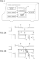
- FIG. 1 is a diagram illustrative of an example of a schematic configuration of a parking assistance device of an embodiment.
- An own vehicle 1 includes a parking assistance device 10 configured to assist parking of the own vehicle 1 at a target parking position.
- parking assistance device 10 In parking assistance performed by the parking assistance device 10, a target travel trajectory from a current position of the own vehicle 1 to the target parking position is calculated.
- autonomous driving to control the own vehicle 1 to travel to the target parking position along the target travel trajectory of the own vehicle 1 is performed.
- the parking assistance device 10 includes a positioning device 11, an object sensor 12, vehicle sensors 13, a controller 14, and actuators 15.
- the positioning device 11 measures a current position of the own vehicle 1.
- the positioning device 11 may include, for example, a global navigation satellite system (GNSS) receiver.
- GNSS global navigation satellite system
- the GNSS receiver is a global positioning system (GPS) receiver and receives radio waves from a plurality of navigation satellites and thereby measures the current position of the own vehicle 1.
- GPS global positioning system
- the object sensor 12 detects an object in a predetermined distance range from the own vehicle 1 (for example, a detection range of the object sensor 12).
- the object sensor 12 detects a surrounding environment around the own vehicle 1, such as a relative position between an object existing in surroundings around the own vehicle 1 and the own vehicle 1, distance between the own vehicle 1 and the object, and a direction in which the object exists.
- the object sensor 12 may include, for example, a camera to capture the surrounding environment around the own vehicle 1.
- the object sensor 12 may include a ranging device, such as a laser range finder (LRF), a radar, or a laser radar like a light detection and ranging (LiDAR).
- LRF laser range finder
- LiDAR light detection and ranging
- the vehicle sensors 13 detect various information (vehicle information) that can be acquired from the own vehicle 1.
- the vehicle sensors 13 include, for example, a vehicle speed sensor configured to detect traveling speed (vehicle speed) of the own vehicle 1, wheel speed sensors configured to detect rotational speed of respective tires that the own vehicle 1 has, a triaxial acceleration sensor (G sensor) configured to detect acceleration (including deceleration) in three axial directions of the own vehicle 1, a steering angle sensor configured to detect a steering angle (including a turning angle), a gyro sensor configured to detect angular velocity generated in the own vehicle 1, and a yaw rate sensor configured to detect a yaw rate.
- G sensor triaxial acceleration sensor
- the controller 14 is an electronic control unit (ECU) that performs parking assistance control of the own vehicle 1.
- the controller 14 includes a processor 14a and peripheral components, such as a storage device 14b.
- the processor 14a may be, for example, a central processing unit (CPU) or a micro-processing unit (MPU).
- the storage device 14b may include a semiconductor storage device, a magnetic storage device, an optical storage device, and the like.
- controller 14 Functions of the controller 14, which will be described below, are achieved by, for example, the processor 14a executing computer programs stored in the storage device 14b. Note that the controller 14 may be formed using dedicated hardware for performing various types of information processing that will be described below.
- the actuators 15 operate a steering wheel, accelerator opening, and a braking device of the own vehicle 1 in accordance with control signals output from the controller 14 and thereby generate vehicle behavior of the own vehicle 1.
- the actuators 15 include a steering actuator, an accelerator opening actuator, and a brake control actuator.
- the steering actuator controls steering direction and the amount of steering in the steering of the own vehicle 1.
- the accelerator opening actuator controls the accelerator opening of the own vehicle 1.
- the brake control actuator controls braking action of the braking device of the own vehicle 1.
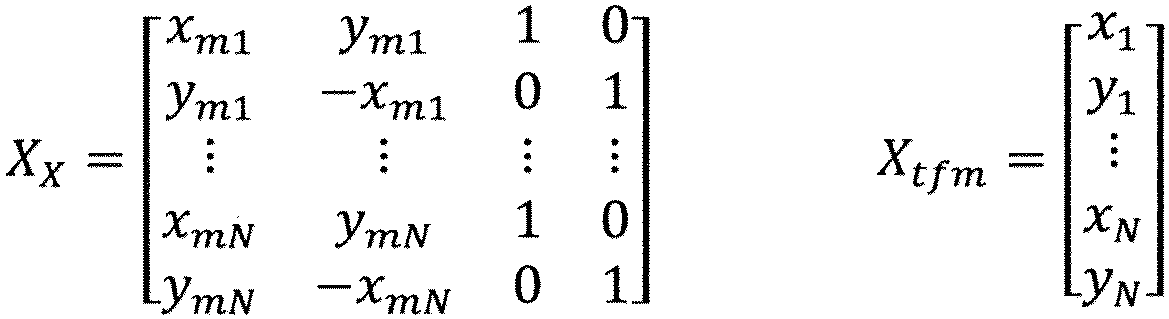
- FIG. 2A is now referred to.
- the driver causes the parking assistance device 10 to store a target object existing around a target parking position 2 that is a target position at which the own vehicle 1 is to be parked and a relative positional relationship between the target object and the target parking position 2 in the storage device 14b.
- the target object is a ground object serving as a mark for specifying the current position of the own vehicle 1 and may be, for example, a pavement marking drawn on a road surface (a lane boundary line 3a, a stop line 3b, a road sign, or the like), a road boundary (curbs 3c to 3e, a guardrail, or the like), or an obstacle (a house 3f, a wall 3g, an object 3h, or the like).
- parking assistance data Data obtained by combining a known target object stored in the storage device 14b and a relative positional relationship between the known target object and the target parking position 2 as described above are sometimes referred to as "parking assistance data" in the following description.
- an operation mode of the parking assistance device 10 is set to a "target object learning mode". Subsequently, the driver parks the own vehicle 1 at the target parking position 2 by manual driving.
- the parking assistance device 10 While the own vehicle 1 is moved to be parked at the target parking position 2 by manual driving, the parking assistance device 10 detects a target object around the own vehicle 1 and a target object position that is a relative position of the target object with respect to the own vehicle 1, by the object sensor 12.
- the parking assistance device 10 detects edge portions or corner portions of target objects, such as pavement markings (in the example in FIG. 2A , the lane boundary line 3a and the stop line 3b), road boundaries (in the example in FIG. 2A , ground contacting portions of the curbs 3c to 3e), and obstacles (in the example of FIG. 2A , ground contacting portions of the house 3f, the wall 3g, and the object 3h), in a captured image obtained by image capturing using the camera of the object sensor 12, as feature points.
- target objects such as pavement markings (in the example in FIG. 2A , the lane boundary line 3a and the stop line 3b), road boundaries (in the example in FIG. 2A , ground contacting portions of the curbs 3c to 3e), and obstacles (in the example of FIG. 2A , ground contacting portions of the house 3f, the wall 3g, and the object 3h), in a captured image obtained by image capturing using the camera of the object sensor 12, as feature points.
- target objects such as
- the parking assistance device 10 also calculates feature amounts of the detected feature points.
- the feature amount may be, for example, vector data calculated from a neighboring area of a feature point in an image.
- various methods such as SIFT, SURF, ORB, BRIAK, KAZE, and AKAZE, can be made use of.
- the parking assistance device 10 calculates, based on positions of feature points in an image and camera information relating to an attachment state (an attachment position, an optical axis angle, and an angle of view) of the camera to the own vehicle 1, relative positions of the feature points with respect to the own vehicle 1.
- the parking assistance device 10 may detect a feature point of point group information acquired by the laser range finder, the radar, or the LiDAR.
- a feature point is detected from a captured image.
- the parking assistance device 10 calculates a relative positional relationship between a target object (feature point) detected by the object sensor 12 and the target parking position 2. For example, the parking assistance device 10 estimates a current position of the own vehicle 1 in a fixed coordinate system at a time point at which the target object is detected by the object sensor 12 and calculates, based on the estimated current position and the relative position of the target object with respect to the own vehicle 1, a position of the target object in the fixed coordinate system.
- the fixed coordinate system is a coordinate system with the origin set at a specific point (for example, a map coordinate system).
- the parking assistance device 10 detects a position of the own vehicle 1 when the own vehicle 1 is positioned at the target parking position 2, as a position of the target parking position 2 in the fixed coordinate system.
- the position of the target object and the position of the target parking position 2 being determined in the fixed coordinate system causes a relative positional relationship between the target object and the target parking position 2 to be determined.
- the current position of the own vehicle 1 in the fixed coordinate system may be estimated by, for example, the positioning device 11, odometry, or dead reckoning.
- the current position of the own vehicle 1 in the fixed coordinate system may be estimated by map mapping or the like between a target object detected by the object sensor 12 and a known target object position or high-definition map information storing target object positions in advance.
- the parking assistance device 10 may calculate a relative positional relationship between a target object and the target parking position 2, based on the target object position that is detected by the object sensor 12 when the own vehicle 1 is positioned at the target parking position 2.
- the parking assistance device 10 stores parking assistance data obtained by combining information about a target object (that is, a feature amount of a feature point) and a relative positional relationship between the target object and the target parking position 2, in the storage device 14b.
- the parking assistance device 10 may store, as data of a relative positional relationship, the position of a target object and the position of the target parking position 2 in the fixed coordinate system or the position of a target object in a fixed coordinate system with the coordinate origin set at the target parking position 2.
- a target object stored in the storage device 14b is sometimes referred to as a "learned target object".
- Circular marks in FIG. 2A represent learned target objects stored in the storage device 14b.
- the parking assistance device 10 may store, with respect to each of a plurality of different target parking positions, parking assistance data for performing parking assistance at the target parking position, in the storage device 14b.
- parking assistance performed by the parking assistance device 10 becomes ready to use.
- the operation mode of the parking assistance device 10 is set to a "parking assistance mode".
- the parking assistance device 10 retrieves the parking assistance data from the storage device 14b.
- the parking assistance device 10 selects and retrieves parking assistance data that are stored with respect to a target parking position at which the own vehicle 1 is to be parked.
- the parking assistance device 10 may retrieve parking assistance data corresponding to the current position of the own vehicle 1 measured by the positioning device 11.
- the parking assistance device 10 may retrieve parking assistance data that are stored with respect to a target parking position closest to the current position of the own vehicle 1.
- the parking assistance device 10 may store attribute data (for example, "a parking lot of an own house” or "a parking lot of a workplace") of parking assistance data in the storage device 14b, and a passenger (for example, a driver) may select parking assistance data to be retrieved from the storage device 14b, based on the attribute data.
- attribute data for example, "a parking lot of an own house” or "a parking lot of a workplace”
- a passenger for example, a driver
- Circular marks in FIG. 2B represent learned target objects retrieved from the storage device 14b in the parking assistance mode.
- the parking assistance device 10 detects a target object around the own vehicle 1 and a target object position that is a relative position of the target object with respect to the own vehicle 1, by the object sensor 12.
- a detection method of a target object and a target object position is the same as the detection method in the target object learning mode.
- a target object that the object sensor 12 detects in the parking assistance mode is indicated by a triangular mark.
- corner portions of the lane boundary line 3a, the curbs 3c and 3e, and the wall 3g are detected as feature points of target objects.
- the parking assistance device 10 associates the same target objects with each other among the respective target objects detected by the object sensor 12 in the parking assistance mode (triangular marks) and the learned target objects stored in the storage device 14b (circular marks). For example, the parking assistance device 10 may determine target objects represented by feature points having the same or similar feature amounts to be the same target objects. In the example in FIG. 2B , the corner portions of each of the lane boundary line 3a, the curbs 3c and 3e, and the wall 3g are associated with each other.
- the parking assistance device 10 calculates, based on relative positional relationships between the respective target objects detected in the parking assistance mode (triangular marks) and the own vehicle 1 and relative positional relationships between learned target objects (circular marks) associated with the detected target objects (triangular marks) and the target parking position 2, a relative position of the target parking position 2 with respect to the current position of the own vehicle 1. For example, the parking assistance device 10 may calculate the position of the target parking position 2 in a relative coordinate system with reference to the current position of the own vehicle 1 (hereinafter, referred to as a "vehicle coordinate system").
- the parking assistance device 10 may calculate, based on the relative positional relationships between the respective target objects detected in the parking assistance mode (triangular marks) and the own vehicle 1 and the learned target objects in the fixed coordinate system (circular marks), the current position of the own vehicle 1 in the fixed coordinate system.
- the position of the own vehicle 1 and the position of the target parking position 2 in the fixed coordinate system being determined causes the relative position of the target parking position 2 with respect to the current position of the own vehicle 1 to be determined.
- the parking assistance device 10 calculates, based on the relative position of the target parking position 2 with respect to the current position of the own vehicle 1, a target travel trajectory starting from the current position of the own vehicle 1 and reaching the target parking position 2.
- the parking assistance device 10 performs autonomous driving to control the own vehicle 1 to travel to the target parking position along the calculated target travel trajectory.
- a relative position of the target parking position 2 with respect to the own vehicle 1 (hereinafter, also simply referred to as a relative position of the target parking position 2), based on the target objects detected by the sensor mounted on the own vehicle 1 and known relative positional relationships between the target parking position 2 and the target objects and controlling the own vehicle 1 to travel to the target parking position 2, as described above sometimes give the passenger a sense of discomfort.
- a relative position of the target parking position 2 is low, precision of the control to cause the own vehicle 1 to travel to the target parking position 2 deteriorates, there is a risk that the passenger is given a sense of discomfort.
- the parking assistance device 10 determines the estimation precision of the relative position of the target parking position 2 and the estimation precision is low, the parking assistance device 10 limits a speed limit of movement speed at which the own vehicle 1 is caused to travel along the target travel trajectory to a speed lower than a speed limit when the estimation precision is high. Because of this configuration, since when the estimation precision of the relative position of the target parking position 2 is low, the movement speed at which the own vehicle 1 travels to the target parking position 2 becomes low, a sense of discomfort given to the passenger can be suppressed.
- the controller 14 functions as an image conversion unit 40, a self-position calculation unit 41, a feature point detection unit 42, a map generation unit 43, a relative position estimation unit 45, an estimation precision determination unit 46, a target trajectory generation unit 47, a steering control unit 48, and a vehicle speed control unit 49.
- the self-position calculation unit 41 calculates a current position of the own vehicle 1 in the fixed coordinate system by dead reckoning or the like based on vehicle information output from the vehicle sensors 13.
- the self-position calculation unit 41 may correct the calculated current position by map mapping or the like between a target object detected by the object sensor 12 and a known target object position or the high-definition map information.
- the feature point detection unit 42 detects a feature point of a target object around the own vehicle 1 from the surrounding image output from the image conversion unit 40 and calculates a feature amount of the feature point.
- the feature point detection unit 42 outputs the detected feature point and the feature amount of the feature point to the map generation unit 43 and the relative position estimation unit 45 in conjunction with the current position of the own vehicle 1 received from the self-position calculation unit 41.
- the map generation unit 43 stores feature point information including a feature point output from the feature point detection unit 42 while the driver parks the own vehicle 1 at the target parking position 2 by manual driving, a current position of the own vehicle 1 synchronized with the feature point, and a feature amount of the feature point, in the storage device 14b as parking assistance data 44.
- the map generation unit 43 may calculate a position of a feature point in the fixed coordinate system, based on the current position of the own vehicle 1 and store the calculated position as feature point information.
- the parking assistance data 44 stored in the storage device 14b are only required to include at least a relative positional relationship between the position of a feature point and the position of the target parking position 2 and do not necessarily have to include the feature amount of the feature point.
- information including the position of a feature point or the position and feature amount of a feature point is also referred to as feature point information.
- the relative position estimation unit 45 retrieves the parking assistance data 44 from the storage device 14b.
- the relative position estimation unit 45 by matching feature point information of learned target objects stored as the parking assistance data 44 (circular marks in FIG. 2A ) with feature point information that the feature point detection unit 42 outputs from a captured image output from the camera of the object sensor 12 in the parking assistance mode (triangular marks in FIG. 2B ), associates pieces of feature point information detected with respected to the same target object with each other.
- the relative position estimation unit 45 estimates, based on relative positional relationships between the feature points detected in the parking assistance mode (triangular marks) and the own vehicle 1 and relative positional relationships between the feature point information of learned target objects (circular marks) associated with the detected feature points (triangular marks) and the target parking position 2, a relative position of the target parking position 2 with respect to the current position of the own vehicle 1.
- the relative position estimation unit 45 may calculate an affine transformation matrix M affine , using the following equation, based on a least-square method.
- a 1 a 2 a 3 a 4 X X T X X ⁇ 1 X X T X tfm
- X X x m 1 y m 1 1 0 y m 1 ⁇ x m 1 0 1 ⁇ ⁇ ⁇ ⁇ x mN y mN 1 0 y mN ⁇ x mN 0 1
- the relative position estimation unit 45 may calculate a column vector (a 1 , a 2 , a 3 , a 4 ) T as in the following equation, using a least-square method.
- the relative position estimation unit 45 converts a position (targetx m , targety m ) of the target parking position 2 in the fixed coordinate system, which is stored in the parking assistance data 44, to a position (targetx, targety) in the vehicle coordinate system, using the following equation.
- targetx targety M affine targetx m targety m 1
- the relative position estimation unit 45 may calculate, based on the determined positions of the feature points of the learned target objects in the vehicle coordinate system and relative positional relationships between the positions of the feature points of the learned target objects and the target parking position 2, the position (targetx, targety) in the vehicle coordinate system of the target parking position 2.
- the estimation precision determination unit 46 determines estimation precision of the relative position of the target parking position 2 with respect to the current position of the own vehicle 1, the relative position being estimated by the relative position estimation unit 45.
- the estimation precision determination unit 46 may determine that the estimation precision is lower than estimation precision when the number of detected feature points is large. For example, the estimation precision determination unit 46 may determine that the smaller the number of feature points detected in the parking assistance mode is, the lower the estimation precision is.
- the estimation precision determination unit 46 may determine that the estimation precision is lower than estimation precision when the number of learned target objects is large. For example, the estimation precision determination unit 46 may determine that the smaller the number of learned target objects is, the lower the estimation precision is.
- the estimation precision determination unit 46 may estimate the estimation precision, assuming a case where all of one of feature points detected in the parking assistance mode and learned target objects the number of which is smaller than the other are associated with the other, and determine that the smaller the number of the one the number of which is smaller than the other is, the lower the estimation precision is.
- the estimation precision determination unit 46 may determine that the estimation precision is lower than estimation precision when the number of learned target objects associated with feature points detected in the parking assistance mode is large. For example, the estimation precision determination unit 46 may determine that the smaller the number of learned target objects associated with feature points detected in the parking assistance mode is, the lower the estimation precision is.
- the estimation precision determination unit 46 may determine that the estimation precision is lower than estimation precision when the minimum value of the average S is small. The estimation precision determination unit 46 may determine that the larger the average S is, the lower the estimation precision is.
- the target trajectory generation unit 47 generates a target travel trajectory starting from the current position of the own vehicle 1 in the vehicle coordinate system (that is, the coordinate origin) and reaching the position (targetx, targety) in the vehicle coordinate system of the target parking position 2.
- the target travel trajectory can be generated by, for example, connecting a clothoid curve from the current position of the own vehicle 1 to the target parking position 2.
- the target trajectory generation unit 47 calculates a movement speed plan (movement speed profile) in which movement speed at each position on the target travel trajectory from the current position of the own vehicle to the target parking position 2 is set. For example, the target trajectory generation unit 47 calculates a movement speed at each position on the target travel trajectory in such a way that the own vehicle 1, from a state of standing still at the current position of the own vehicle, accelerates to a predetermined speed limit at a predetermined acceleration, subsequently decelerates from the speed limit at a predetermined deceleration, and stops at the target parking position 2.
- the target trajectory generation unit 47 may set the movement speed in such a manner that the larger the curvature of the target travel trajectory at a point is, the lower the movement speed at the point is.
- the steering control unit 48 controls the steering actuator in the actuators 15 in such a way that the own vehicle 1 travels along the target travel trajectory.
- the vehicle speed control unit 49 controls an accelerator actuator and a brake actuator in the actuators 15 in such a way that the vehicle speed of the own vehicle 1 changes in accordance with the movement speed plan that the target trajectory generation unit 47 calculated. Because of this configuration, the own vehicle 1 is controlled to travel along the target travel trajectory.
- the vehicle speed control unit 49 limits the speed limit of the movement speed at which the own vehicle 1 is caused to travel along the target travel trajectory to a speed lower than a speed limit when the estimation precision is high. For example, the vehicle speed control unit 49 sets the speed limit in such a manner that the lower the estimation precision is, the lower the speed limit is.
- the vehicle speed control unit 49 may calculate a corrected movement speed plan by correcting movement speed at a position at which a movement speed higher than a speed limit that is set according to the estimation precision is set in the movement speed plan calculated by the target trajectory generation unit 47 to the speed limit.
- the vehicle speed control unit 49 may control the accelerator actuator and the brake actuator in the actuators 15 in such a way that the vehicle speed of the own vehicle 1 changes in accordance with the corrected movement speed plan.
- the vehicle speed control unit 49 when controlling the speed of the own vehicle 1 in accordance with the movement speed plan that the target trajectory generation unit 47 calculated, may determine whether or not the movement speed of the own vehicle 1, which the vehicle speed sensor in the vehicle sensors 13 detects, is higher than the speed limit that is set according to the estimation precision. When the movement speed of the own vehicle 1 is higher than the speed limit, the vehicle speed control unit 49 may control the movement speed of the own vehicle to less than or equal to the speed limit.
- the vehicle speed control unit 49 may determine whether or not distance from the own vehicle 1 to an obstacle around the own vehicle 1 is less than a predetermined threshold and, when the distance from the own vehicle 1 to the obstacle is less than the predetermined threshold, cause the own vehicle 1 to stop.
- Distance information from the own vehicle 1 to an obstacle around the own vehicle 1 may be detected by, for example, the object sensor 12.
- the target trajectory generation unit 47 may calculate a target travel trajectory only once when the parking assistance by the parking assistance device 10 is started or may, after the own vehicle 1 starts travel to the target parking position 2 along a target travel trajectory, regenerate a target travel trajectory and update the original target travel trajectory. For example, the target trajectory generation unit 47 may repeatedly update a target travel trajectory at a predetermined period.
- the feature point detection unit 42 detects a feature point of a target object around the own vehicle 1 from an image captured by the camera of the object sensor 12 after travel to the target parking position 2 is started.
- the relative position estimation unit 45 by associating a feature point that the feature point detection unit 42 detects after travel to the target parking position 2 is started with a feature point of a learned target object that is stored as the parking assistance data 44, re-estimates a relative position of the target parking position 2 with respect to the current position of the own vehicle 1.
- the estimation precision determination unit 46 determines estimation precision of the re-estimated relative position of the target parking position 2. In general, since the closer the own vehicle 1 comes to the target parking position 2, the larger the number of detected target objects that can be associated with learned target objects becomes, the estimation precision tends to increase.
- the target trajectory generation unit 47 regenerates, based on the re-estimated relative position of the target parking position 2, a target travel trajectory starting from the current position of the own vehicle 1 and reaching the target parking position 2. In addition, the target trajectory generation unit 47 updates the movement speed plan, based on the regenerated target travel trajectory. On this occasion, the target trajectory generation unit 47 sets a current vehicle speed of the own vehicle 1 that the vehicle sensors 13 detected to a movement speed (initial value) at the current position.
- the steering control unit 48 controls the steering actuator in such a way that the own vehicle 1 travels along the regenerated target travel trajectory.
- the vehicle speed control unit 49 controls the actuators 15 in such a way that the vehicle speed of the own vehicle 1 changes in accordance with the updated movement speed plan.
- the vehicle speed control unit 49 limits the speed limit of the movement speed at which the own vehicle 1 is caused to travel along the target travel trajectory to a speed lower than a speed limit when the estimation precision is high.
- FIG. 4 is a flowchart of an example of operation of the parking assistance device 10 in the parking assistance mode.
- step S1 the positioning device 11 measures a current position of the own vehicle 1 in the fixed coordinate system.
- step S2 the object sensor 12 detects a feature point of a target object around the own vehicle 1.
- step S3 the relative position estimation unit 45 of the controller 14 retrieves parking assistance data corresponding to the current position of the own vehicle 1 from the storage device 14b.
- step S4 the relative position estimation unit 45 determines an association between the feature point of the target object detected in step S2 and a feature point of a known target object in the parking assistance data retrieved in step S3.
- step S5 the relative position estimation unit 45 estimates, based on a relative position of the feature point of the target object detected in step S2 with respect to the own vehicle 1 and a relative positional relationship between the feature point of the known target object associated with the feature point of the target object detected in step S2 and the target parking position 2, a relative position of the target parking position 2 with respect to the own vehicle 1.
- step S6 the estimation precision determination unit 46 determines estimation precision of the relative position in step S5.
- step S7 when the estimation precision determined in step S6 is low, the vehicle speed control unit 49 limits a speed limit of movement speed at which the own vehicle 1 is caused to travel to the target parking position 2 to a speed lower than a speed limit when the estimation precision is high.
- step S8 the target trajectory generation unit 47 generates, based on the relative position of the target parking position 2 with respect to the own vehicle 1 that is estimated in step S5, a target travel trajectory that the own vehicle is caused to travel from the current position of the own vehicle 1 to the target parking position 2.
- step S9 the target trajectory generation unit 47 calculates a movement speed plan in which movement speed at each position on the target travel trajectory is set.
- step S10 the vehicle speed control unit 49 limits the movement speed plan calculated in step S9 by the speed limit set in step S7.
- step S11 the steering control unit 48 controls a steering angle in such a way that the own vehicle 1 travels along the target travel trajectory generated in step S8.
- the vehicle speed control unit 49 controls the movement speed of the own vehicle 1 in accordance with the movement speed plan limited in step S10.
- the process terminates.
- the controller 14 may determine that when the number of target objects detected by the object sensor 12 is small, the estimation precision is lower than estimation precision when the number of target objects is large.
- the controller 14 may determine that when the number of known target objects stored in the storage device 14b is small, the estimation precision is lower than estimation precision when the number of known target objects is large.
- the controller 14 may, by associating a target object detected by the object sensor 12 with a known target object stored in the storage device 14b, estimate a relative position of the target parking position with respect to the current position of the own vehicle 1 and, when the number of known target objects associated with target objects detected by the object sensor 12 is small, determine that estimation precision is lower than estimation precision when the number of known target objects associated with target objects detected by the object sensor 12 is large.
- the controller 14 may estimate a relative position of the target parking position with respect to the current position of the own vehicle 1 in such a manner that an average of respective distances between a plurality of target objects detected by the object sensor 12 and a plurality of known target objects stored in the storage device 14b becomes small and, when the average is large, determine that the estimation precision is lower than estimation precision when the average is small.
- the controller 14 may calculate a movement speed plan in which movement speed at each position on a target travel trajectory from the current position of the own vehicle 1 to the target parking position is set, calculate a corrected movement speed plan by correcting movement speed at a position at which a movement speed higher than a speed limit is set in the movement speed plan, to the speed limit, and based on the corrected movement speed plan, control the movement speed at which the own vehicle 1 is caused to travel along the target travel trajectory.
- the vehicle sensor 13 detects movement speed of the own vehicle 1.
- the controller 14 may control the movement speed of the own vehicle 1 to less than or equal to the speed limit.
- Distance from the own vehicle 1 to an obstacle around the own vehicle 1 may be detected by the object sensor 12, and when the detected distance is less than a predetermined distance, the own vehicle may be caused to stop.
Landscapes
- Engineering & Computer Science (AREA)
- Transportation (AREA)
- Mechanical Engineering (AREA)
- Automation & Control Theory (AREA)
- Chemical & Material Sciences (AREA)
- Combustion & Propulsion (AREA)
- Physics & Mathematics (AREA)
- General Physics & Mathematics (AREA)
- Control Of Driving Devices And Active Controlling Of Vehicle (AREA)
- Traffic Control Systems (AREA)
Abstract
Description
- The present invention relates to a parking assistance method and a parking assistance device.
- In
PTL 1 described below, a technology to recognize and store a feature point around a target parking position, calculate a relative position of the target parking position with respect to an own vehicle, based on a relative position of the own vehicle with respect to the stored feature point, and cause the own vehicle to autonomously move to the target parking position, based on the calculated relative position is described. - PTL1:
JP 2017-138664 A - However, when the own vehicle is caused to move based on the relative position when calculation precision of the relative position between the target parking position and the own vehicle is low, there is a risk that a passenger is given a sense of discomfort.
- An object of the present invention is to reduce a sense of discomfort given to a passenger when an own vehicle is caused to move to a target parking position, based on a target object detected by a sensor mounted on the own vehicle and a known relative positional relationship between the target parking position and the target object.
- According to an aspect of the present invention, there is provided a parking assistance method including: by a sensor mounted on an own vehicle, detecting a target object around the own vehicle and a target object position, the target object position being a relative position of the target object with respect to the own vehicle; retrieving a known target object and a relative positional relationship between the known target object and a target parking position, the known target object and the relative positional relationship being stored in a predetermined storage device in advance, from the storage device; based on a target object position detected by the sensor and a relative positional relationship between the known target object and a target parking position, estimating a relative position of the target parking position with respect to a current position of the own vehicle; based on the estimated relative position, calculating a target travel trajectory from a current position of the own vehicle to a relative position of the target parking position; determining estimation precision of the estimated relative position; and when the estimation precision is low, limiting a speed limit of movement speed at which the own vehicle is caused to travel along the target travel trajectory to a speed lower than a speed limit when the estimation precision is high.
- According to an aspect of the present invention, it is possible to reduce a sense of discomfort given to a passenger when an own vehicle is caused to move to a target parking position, based on a target object detected by a sensor mounted on the own vehicle and a known relative positional relationship between the target parking position and the target object.
- The object and advantages of the invention will be realized and attained by means of the elements and combinations particularly pointed out in the claims. It is to be understood that both the foregoing general description and the following detailed description are exemplary and explanatory and are not restrictive of the invention.
-
-
FIG. 1 is a diagram illustrative of an example of a schematic configuration of a parking assistance device of an embodiment; -
FIG. 2A is an explanatory diagram of an example of learned target objects; -
FIG. 2B is an explanatory diagram of an example of a parking assistance method; -
FIG. 3 is a block diagram of an example of a functional configuration of a controller inFIG. 1 ; and -
FIG. 4 is a flowchart of an example of a driving assistance method of the embodiment. -
FIG. 1 is a diagram illustrative of an example of a schematic configuration of a parking assistance device of an embodiment. Anown vehicle 1 includes aparking assistance device 10 configured to assist parking of theown vehicle 1 at a target parking position. In parking assistance performed by theparking assistance device 10, a target travel trajectory from a current position of theown vehicle 1 to the target parking position is calculated. In the parking assistance, autonomous driving to control theown vehicle 1 to travel to the target parking position along the target travel trajectory of theown vehicle 1 is performed. Theparking assistance device 10 includes apositioning device 11, anobject sensor 12,vehicle sensors 13, acontroller 14, andactuators 15. - The
positioning device 11 measures a current position of theown vehicle 1. Thepositioning device 11 may include, for example, a global navigation satellite system (GNSS) receiver. The GNSS receiver is a global positioning system (GPS) receiver and receives radio waves from a plurality of navigation satellites and thereby measures the current position of theown vehicle 1. - The
object sensor 12 detects an object in a predetermined distance range from the own vehicle 1 (for example, a detection range of the object sensor 12). Theobject sensor 12 detects a surrounding environment around theown vehicle 1, such as a relative position between an object existing in surroundings around theown vehicle 1 and theown vehicle 1, distance between theown vehicle 1 and the object, and a direction in which the object exists. Theobject sensor 12 may include, for example, a camera to capture the surrounding environment around theown vehicle 1. Theobject sensor 12 may include a ranging device, such as a laser range finder (LRF), a radar, or a laser radar like a light detection and ranging (LiDAR). - The
vehicle sensors 13 detect various information (vehicle information) that can be acquired from theown vehicle 1. Thevehicle sensors 13 include, for example, a vehicle speed sensor configured to detect traveling speed (vehicle speed) of theown vehicle 1, wheel speed sensors configured to detect rotational speed of respective tires that theown vehicle 1 has, a triaxial acceleration sensor (G sensor) configured to detect acceleration (including deceleration) in three axial directions of theown vehicle 1, a steering angle sensor configured to detect a steering angle (including a turning angle), a gyro sensor configured to detect angular velocity generated in theown vehicle 1, and a yaw rate sensor configured to detect a yaw rate. - The
controller 14 is an electronic control unit (ECU) that performs parking assistance control of theown vehicle 1. Thecontroller 14 includes aprocessor 14a and peripheral components, such as astorage device 14b. Theprocessor 14a may be, for example, a central processing unit (CPU) or a micro-processing unit (MPU). Thestorage device 14b may include a semiconductor storage device, a magnetic storage device, an optical storage device, and the like. - Functions of the
controller 14, which will be described below, are achieved by, for example, theprocessor 14a executing computer programs stored in thestorage device 14b. Note that thecontroller 14 may be formed using dedicated hardware for performing various types of information processing that will be described below. - The
actuators 15 operate a steering wheel, accelerator opening, and a braking device of theown vehicle 1 in accordance with control signals output from thecontroller 14 and thereby generate vehicle behavior of theown vehicle 1. Theactuators 15 include a steering actuator, an accelerator opening actuator, and a brake control actuator. The steering actuator controls steering direction and the amount of steering in the steering of theown vehicle 1. The accelerator opening actuator controls the accelerator opening of theown vehicle 1. The brake control actuator controls braking action of the braking device of theown vehicle 1. - Next, an example of the parking assistance control performed by the
parking assistance device 10 of the embodiment will be described. -
FIG. 2A is now referred to. When a driver makes use of the parking assistance performed by theparking assistance device 10, first, the driver causes theparking assistance device 10 to store a target object existing around atarget parking position 2 that is a target position at which theown vehicle 1 is to be parked and a relative positional relationship between the target object and thetarget parking position 2 in thestorage device 14b. The target object is a ground object serving as a mark for specifying the current position of theown vehicle 1 and may be, for example, a pavement marking drawn on a road surface (alane boundary line 3a, astop line 3b, a road sign, or the like), a road boundary (curbs 3c to 3e, a guardrail, or the like), or an obstacle (ahouse 3f, awall 3g, anobjet 3h, or the like). - Data obtained by combining a known target object stored in the
storage device 14b and a relative positional relationship between the known target object and thetarget parking position 2 as described above are sometimes referred to as "parking assistance data" in the following description. - In order to cause the
parking assistance device 10 to store the parking assistance data in thestorage device 14b, an operation mode of theparking assistance device 10 is set to a "target object learning mode". Subsequently, the driver parks theown vehicle 1 at thetarget parking position 2 by manual driving. - While the
own vehicle 1 is moved to be parked at thetarget parking position 2 by manual driving, theparking assistance device 10 detects a target object around theown vehicle 1 and a target object position that is a relative position of the target object with respect to theown vehicle 1, by theobject sensor 12. - For example, the
parking assistance device 10 detects edge portions or corner portions of target objects, such as pavement markings (in the example inFIG. 2A , thelane boundary line 3a and thestop line 3b), road boundaries (in the example inFIG. 2A , ground contacting portions of thecurbs 3c to 3e), and obstacles (in the example ofFIG. 2A , ground contacting portions of thehouse 3f, thewall 3g, and theobjet 3h), in a captured image obtained by image capturing using the camera of theobject sensor 12, as feature points. - The
parking assistance device 10 also calculates feature amounts of the detected feature points. In this configuration, the feature amount may be, for example, vector data calculated from a neighboring area of a feature point in an image. For detection of a feature point and calculation of a feature amount, various methods, such as SIFT, SURF, ORB, BRIAK, KAZE, and AKAZE, can be made use of. - In addition, the
parking assistance device 10 calculates, based on positions of feature points in an image and camera information relating to an attachment state (an attachment position, an optical axis angle, and an angle of view) of the camera to theown vehicle 1, relative positions of the feature points with respect to theown vehicle 1. - Note that the
parking assistance device 10 may detect a feature point of point group information acquired by the laser range finder, the radar, or the LiDAR. Herein, an example in which a feature point is detected from a captured image will be described. - Next, the
parking assistance device 10 calculates a relative positional relationship between a target object (feature point) detected by theobject sensor 12 and thetarget parking position 2. For example, theparking assistance device 10 estimates a current position of theown vehicle 1 in a fixed coordinate system at a time point at which the target object is detected by theobject sensor 12 and calculates, based on the estimated current position and the relative position of the target object with respect to theown vehicle 1, a position of the target object in the fixed coordinate system. As used herein, the fixed coordinate system is a coordinate system with the origin set at a specific point (for example, a map coordinate system). Next, theparking assistance device 10 detects a position of theown vehicle 1 when theown vehicle 1 is positioned at thetarget parking position 2, as a position of thetarget parking position 2 in the fixed coordinate system. The position of the target object and the position of thetarget parking position 2 being determined in the fixed coordinate system causes a relative positional relationship between the target object and thetarget parking position 2 to be determined. - The current position of the
own vehicle 1 in the fixed coordinate system may be estimated by, for example, thepositioning device 11, odometry, or dead reckoning. The current position of theown vehicle 1 in the fixed coordinate system may be estimated by map mapping or the like between a target object detected by theobject sensor 12 and a known target object position or high-definition map information storing target object positions in advance. - In addition, the
parking assistance device 10 may calculate a relative positional relationship between a target object and thetarget parking position 2, based on the target object position that is detected by theobject sensor 12 when theown vehicle 1 is positioned at thetarget parking position 2. - The
parking assistance device 10 stores parking assistance data obtained by combining information about a target object (that is, a feature amount of a feature point) and a relative positional relationship between the target object and thetarget parking position 2, in thestorage device 14b. Theparking assistance device 10 may store, as data of a relative positional relationship, the position of a target object and the position of thetarget parking position 2 in the fixed coordinate system or the position of a target object in a fixed coordinate system with the coordinate origin set at thetarget parking position 2. Hereinafter, a target object stored in thestorage device 14b is sometimes referred to as a "learned target object". - Circular marks in
FIG. 2A represent learned target objects stored in thestorage device 14b. - The
parking assistance device 10 may store, with respect to each of a plurality of different target parking positions, parking assistance data for performing parking assistance at the target parking position, in thestorage device 14b. - When the parking assistance data are stored in the
storage device 14b, parking assistance performed by theparking assistance device 10 becomes ready to use. In order to use the parking assistance, the operation mode of theparking assistance device 10 is set to a "parking assistance mode". - In the parking assistance mode, the
parking assistance device 10 retrieves the parking assistance data from thestorage device 14b. When parking assistance data is stored with respect to each of the plurality of different target parking positions, theparking assistance device 10 selects and retrieves parking assistance data that are stored with respect to a target parking position at which theown vehicle 1 is to be parked. - For example, the
parking assistance device 10 may retrieve parking assistance data corresponding to the current position of theown vehicle 1 measured by thepositioning device 11. For example, theparking assistance device 10 may retrieve parking assistance data that are stored with respect to a target parking position closest to the current position of theown vehicle 1. - In addition, the
parking assistance device 10 may store attribute data (for example, "a parking lot of an own house" or "a parking lot of a workplace") of parking assistance data in thestorage device 14b, and a passenger (for example, a driver) may select parking assistance data to be retrieved from thestorage device 14b, based on the attribute data. - Circular marks in
FIG. 2B represent learned target objects retrieved from thestorage device 14b in the parking assistance mode. - The
parking assistance device 10 detects a target object around theown vehicle 1 and a target object position that is a relative position of the target object with respect to theown vehicle 1, by theobject sensor 12. A detection method of a target object and a target object position is the same as the detection method in the target object learning mode. - A target object that the
object sensor 12 detects in the parking assistance mode is indicated by a triangular mark. In the example inFIG. 2B , corner portions of thelane boundary line 3a, thecurbs wall 3g are detected as feature points of target objects. - The
parking assistance device 10 associates the same target objects with each other among the respective target objects detected by theobject sensor 12 in the parking assistance mode (triangular marks) and the learned target objects stored in thestorage device 14b (circular marks). For example, theparking assistance device 10 may determine target objects represented by feature points having the same or similar feature amounts to be the same target objects. In the example inFIG. 2B , the corner portions of each of thelane boundary line 3a, thecurbs wall 3g are associated with each other. - The
parking assistance device 10 calculates, based on relative positional relationships between the respective target objects detected in the parking assistance mode (triangular marks) and theown vehicle 1 and relative positional relationships between learned target objects (circular marks) associated with the detected target objects (triangular marks) and thetarget parking position 2, a relative position of thetarget parking position 2 with respect to the current position of theown vehicle 1. For example, theparking assistance device 10 may calculate the position of thetarget parking position 2 in a relative coordinate system with reference to the current position of the own vehicle 1 (hereinafter, referred to as a "vehicle coordinate system"). Alternatively, theparking assistance device 10 may calculate, based on the relative positional relationships between the respective target objects detected in the parking assistance mode (triangular marks) and theown vehicle 1 and the learned target objects in the fixed coordinate system (circular marks), the current position of theown vehicle 1 in the fixed coordinate system. The position of theown vehicle 1 and the position of thetarget parking position 2 in the fixed coordinate system being determined causes the relative position of thetarget parking position 2 with respect to the current position of theown vehicle 1 to be determined. - The
parking assistance device 10 calculates, based on the relative position of thetarget parking position 2 with respect to the current position of theown vehicle 1, a target travel trajectory starting from the current position of theown vehicle 1 and reaching thetarget parking position 2. Theparking assistance device 10 performs autonomous driving to control theown vehicle 1 to travel to the target parking position along the calculated target travel trajectory. - Estimating a relative position of the
target parking position 2 with respect to the own vehicle 1 (hereinafter, also simply referred to as a relative position of the target parking position 2), based on the target objects detected by the sensor mounted on theown vehicle 1 and known relative positional relationships between thetarget parking position 2 and the target objects and controlling theown vehicle 1 to travel to thetarget parking position 2, as described above sometimes give the passenger a sense of discomfort. For example, since when estimation precision of the relative position of thetarget parking position 2 is low, precision of the control to cause theown vehicle 1 to travel to thetarget parking position 2 deteriorates, there is a risk that the passenger is given a sense of discomfort. - Therefore, when the
parking assistance device 10 determines the estimation precision of the relative position of thetarget parking position 2 and the estimation precision is low, theparking assistance device 10 limits a speed limit of movement speed at which theown vehicle 1 is caused to travel along the target travel trajectory to a speed lower than a speed limit when the estimation precision is high. Because of this configuration, since when the estimation precision of the relative position of thetarget parking position 2 is low, the movement speed at which theown vehicle 1 travels to thetarget parking position 2 becomes low, a sense of discomfort given to the passenger can be suppressed. - A functional configuration of the
controller 14 will be described in more detail below.FIG. 3 is now referred to. Thecontroller 14 functions as animage conversion unit 40, a self-position calculation unit 41, a featurepoint detection unit 42, amap generation unit 43, a relativeposition estimation unit 45, an estimationprecision determination unit 46, a targettrajectory generation unit 47, asteering control unit 48, and a vehiclespeed control unit 49. - The
image conversion unit 40 converts captured images captured by the camera of theobject sensor 12 to a bird's eye image (an around view monitoring image) that is an image viewed from a virtual viewpoint directly above theown vehicle 1 as illustrated inFIGS. 2A and 2B . Hereinafter, a bird's eye image after conversion by theimage conversion unit 40 is sometimes referred to as a "surrounding image".FIG. 2A is a surrounding image in the target object learning mode, andFIG. 2B is a surrounding image in the parking assistance mode. - The self-
position calculation unit 41 calculates a current position of theown vehicle 1 in the fixed coordinate system by dead reckoning or the like based on vehicle information output from thevehicle sensors 13. The self-position calculation unit 41 may correct the calculated current position by map mapping or the like between a target object detected by theobject sensor 12 and a known target object position or the high-definition map information. - The feature
point detection unit 42 detects a feature point of a target object around theown vehicle 1 from the surrounding image output from theimage conversion unit 40 and calculates a feature amount of the feature point. The featurepoint detection unit 42 outputs the detected feature point and the feature amount of the feature point to themap generation unit 43 and the relativeposition estimation unit 45 in conjunction with the current position of theown vehicle 1 received from the self-position calculation unit 41. - In the target object learning mode, the
map generation unit 43 stores feature point information including a feature point output from the featurepoint detection unit 42 while the driver parks theown vehicle 1 at thetarget parking position 2 by manual driving, a current position of theown vehicle 1 synchronized with the feature point, and a feature amount of the feature point, in thestorage device 14b asparking assistance data 44. Themap generation unit 43 may calculate a position of a feature point in the fixed coordinate system, based on the current position of theown vehicle 1 and store the calculated position as feature point information. - In addition, when the current position of the
own vehicle 1 reaches thetarget parking position 2, themap generation unit 43 receives the current position of theown vehicle 1 in the fixed coordinate system from thepositioning device 11 or the self-position calculation unit 41 and stores thetarget parking position 2 in thestorage device 14b as theparking assistance data 44. For example, the driver may operate a human-machine interface (not illustrated) of theparking assistance device 10 and instruct that the current position of theown vehicle 1 is thetarget parking position 2. Through this operation, thestorage device 14b stores a relative positional relationship between the position of a feature point detected in the target object learning mode and the position of thetarget parking position 2 and the feature amount of the feature point in thestorage device 14b as theparking assistance data 44. Note that theparking assistance data 44 stored in thestorage device 14b are only required to include at least a relative positional relationship between the position of a feature point and the position of thetarget parking position 2 and do not necessarily have to include the feature amount of the feature point. Hereinafter, information including the position of a feature point or the position and feature amount of a feature point is also referred to as feature point information. - When the operating mode of the
parking assistance device 10 is switched to the parking assistance mode, the relativeposition estimation unit 45 retrieves theparking assistance data 44 from thestorage device 14b. The relativeposition estimation unit 45, by matching feature point information of learned target objects stored as the parking assistance data 44 (circular marks inFIG. 2A ) with feature point information that the featurepoint detection unit 42 outputs from a captured image output from the camera of theobject sensor 12 in the parking assistance mode (triangular marks inFIG. 2B ), associates pieces of feature point information detected with respected to the same target object with each other. - The relative
position estimation unit 45 estimates, based on relative positional relationships between the feature points detected in the parking assistance mode (triangular marks) and theown vehicle 1 and relative positional relationships between the feature point information of learned target objects (circular marks) associated with the detected feature points (triangular marks) and thetarget parking position 2, a relative position of thetarget parking position 2 with respect to the current position of theown vehicle 1. - For example, feature points detected in the parking assistance mode are denoted by (xi, yi), and feature points of learned target objects each of which is associated with one of the feature points (xi, yi) are denoted by (xmi, ymi) (i=1 to N). For example, the relative
position estimation unit 45 may calculate an affine transformation matrix Maffine, using the following equation, based on a least-square method.

- The relative
position estimation unit 45 may calculate a column vector (a1, a2, a3, a4)T as in the following equation, using a least-square method.
- The relative
position estimation unit 45 converts a position (targetxm, targetym) of thetarget parking position 2 in the fixed coordinate system, which is stored in theparking assistance data 44, to a position (targetx, targety) in the vehicle coordinate system, using the following equation.
- Instead of this configuration, the relative
position estimation unit 45 may assume positions (xmi, ymi) in the vehicle coordinate system of feature points of learned target objects (i=1 to N), calculate a distance di (i.e. a positional error) between a feature point (xi, yi) of each target object detected in the parking assistance mode and a feature point (xmi, ymi) of a learned target object associated with the feature point (xi, yi), and determine positions of the feature points of the learned target objects in the vehicle coordinate system in such a manner as to minimize an average S=(d1+d2+ ... +dN)/N of the distances di. - The relative
position estimation unit 45 may calculate, based on the determined positions of the feature points of the learned target objects in the vehicle coordinate system and relative positional relationships between the positions of the feature points of the learned target objects and thetarget parking position 2, the position (targetx, targety) in the vehicle coordinate system of thetarget parking position 2. - The estimation
precision determination unit 46 determines estimation precision of the relative position of thetarget parking position 2 with respect to the current position of theown vehicle 1, the relative position being estimated by the relativeposition estimation unit 45. - For example, when the number of feature points detected in the parking assistance mode is small, the estimation
precision determination unit 46 may determine that the estimation precision is lower than estimation precision when the number of detected feature points is large. For example, the estimationprecision determination unit 46 may determine that the smaller the number of feature points detected in the parking assistance mode is, the lower the estimation precision is. - In addition, for example, when the number of learned target objects is small, the estimation
precision determination unit 46 may determine that the estimation precision is lower than estimation precision when the number of learned target objects is large. For example, the estimationprecision determination unit 46 may determine that the smaller the number of learned target objects is, the lower the estimation precision is. - That is, when the number of feature points detected in the parking assistance mode or the number of learned target objects is small, the number of learned target objects associated with feature points detected in the parking assistance mode becomes small and there is a possibility that the estimation precision of the relative position of the
target parking position 2 with respect to the current position of theown vehicle 1 deteriorates. Thus, the estimationprecision determination unit 46 may estimate the estimation precision, assuming a case where all of one of feature points detected in the parking assistance mode and learned target objects the number of which is smaller than the other are associated with the other, and determine that the smaller the number of the one the number of which is smaller than the other is, the lower the estimation precision is. - In addition, for example, when the number of learned target objects associated with feature points detected in the parking assistance mode is small, the estimation
precision determination unit 46 may determine that the estimation precision is lower than estimation precision when the number of learned target objects associated with feature points detected in the parking assistance mode is large. For example, the estimationprecision determination unit 46 may determine that the smaller the number of learned target objects associated with feature points detected in the parking assistance mode is, the lower the estimation precision is. - In addition, for example, when a minimum value of the average S=(d1+d2+ ... +dN)/N of distances (positional error) di between the positions of detected target objects and the positions of the feature points of learned target objects after the target objects detected in the parking assistance mode and the feature points of the learned target objects are subjected to matching (position alignment) is large, the estimation
precision determination unit 46 may determine that the estimation precision is lower than estimation precision when the minimum value of the average S is small. The estimationprecision determination unit 46 may determine that the larger the average S is, the lower the estimation precision is. - In addition, for example, when a residual when an affine transformation matrix Maffine is calculated using the following equation, based on a least-square method is large, the estimation
precision determination unit 46 may determine that the estimation precision is lower than estimation precision when the residual is small. The estimationprecision determination unit 46 may determine that the larger the residual is, the lower the estimation precision is. - The target
trajectory generation unit 47 generates a target travel trajectory starting from the current position of theown vehicle 1 in the vehicle coordinate system (that is, the coordinate origin) and reaching the position (targetx, targety) in the vehicle coordinate system of thetarget parking position 2. Note that the target travel trajectory can be generated by, for example, connecting a clothoid curve from the current position of theown vehicle 1 to thetarget parking position 2. - In addition, the target
trajectory generation unit 47 calculates a movement speed plan (movement speed profile) in which movement speed at each position on the target travel trajectory from the current position of the own vehicle to thetarget parking position 2 is set. For example, the targettrajectory generation unit 47 calculates a movement speed at each position on the target travel trajectory in such a way that theown vehicle 1, from a state of standing still at the current position of the own vehicle, accelerates to a predetermined speed limit at a predetermined acceleration, subsequently decelerates from the speed limit at a predetermined deceleration, and stops at thetarget parking position 2. The targettrajectory generation unit 47 may set the movement speed in such a manner that the larger the curvature of the target travel trajectory at a point is, the lower the movement speed at the point is. - The
steering control unit 48 controls the steering actuator in theactuators 15 in such a way that theown vehicle 1 travels along the target travel trajectory. - In addition, the vehicle
speed control unit 49 controls an accelerator actuator and a brake actuator in theactuators 15 in such a way that the vehicle speed of theown vehicle 1 changes in accordance with the movement speed plan that the targettrajectory generation unit 47 calculated. Because of this configuration, theown vehicle 1 is controlled to travel along the target travel trajectory. - When the estimation precision of the relative position of the
target parking position 2 that the estimationprecision determination unit 46 determined is low, the vehiclespeed control unit 49 limits the speed limit of the movement speed at which theown vehicle 1 is caused to travel along the target travel trajectory to a speed lower than a speed limit when the estimation precision is high. For example, the vehiclespeed control unit 49 sets the speed limit in such a manner that the lower the estimation precision is, the lower the speed limit is. - For example, the vehicle
speed control unit 49 may calculate a corrected movement speed plan by correcting movement speed at a position at which a movement speed higher than a speed limit that is set according to the estimation precision is set in the movement speed plan calculated by the targettrajectory generation unit 47 to the speed limit. The vehiclespeed control unit 49 may control the accelerator actuator and the brake actuator in theactuators 15 in such a way that the vehicle speed of theown vehicle 1 changes in accordance with the corrected movement speed plan. - In addition, the vehicle
speed control unit 49, when controlling the speed of theown vehicle 1 in accordance with the movement speed plan that the targettrajectory generation unit 47 calculated, may determine whether or not the movement speed of theown vehicle 1, which the vehicle speed sensor in thevehicle sensors 13 detects, is higher than the speed limit that is set according to the estimation precision. When the movement speed of theown vehicle 1 is higher than the speed limit, the vehiclespeed control unit 49 may control the movement speed of the own vehicle to less than or equal to the speed limit. - In addition, the vehicle
speed control unit 49 may determine whether or not distance from theown vehicle 1 to an obstacle around theown vehicle 1 is less than a predetermined threshold and, when the distance from theown vehicle 1 to the obstacle is less than the predetermined threshold, cause theown vehicle 1 to stop. Distance information from theown vehicle 1 to an obstacle around theown vehicle 1 may be detected by, for example, theobject sensor 12. - Note that the target
trajectory generation unit 47 may calculate a target travel trajectory only once when the parking assistance by theparking assistance device 10 is started or may, after theown vehicle 1 starts travel to thetarget parking position 2 along a target travel trajectory, regenerate a target travel trajectory and update the original target travel trajectory. For example, the targettrajectory generation unit 47 may repeatedly update a target travel trajectory at a predetermined period. - When a target travel trajectory is to be updated, the feature
point detection unit 42 detects a feature point of a target object around theown vehicle 1 from an image captured by the camera of theobject sensor 12 after travel to thetarget parking position 2 is started. - The relative
position estimation unit 45, by associating a feature point that the featurepoint detection unit 42 detects after travel to thetarget parking position 2 is started with a feature point of a learned target object that is stored as theparking assistance data 44, re-estimates a relative position of thetarget parking position 2 with respect to the current position of theown vehicle 1. In addition, the estimationprecision determination unit 46 determines estimation precision of the re-estimated relative position of thetarget parking position 2. In general, since the closer theown vehicle 1 comes to thetarget parking position 2, the larger the number of detected target objects that can be associated with learned target objects becomes, the estimation precision tends to increase. - The target
trajectory generation unit 47 regenerates, based on the re-estimated relative position of thetarget parking position 2, a target travel trajectory starting from the current position of theown vehicle 1 and reaching thetarget parking position 2. In addition, the targettrajectory generation unit 47 updates the movement speed plan, based on the regenerated target travel trajectory. On this occasion, the targettrajectory generation unit 47 sets a current vehicle speed of theown vehicle 1 that thevehicle sensors 13 detected to a movement speed (initial value) at the current position. - The
steering control unit 48 controls the steering actuator in such a way that theown vehicle 1 travels along the regenerated target travel trajectory. The vehiclespeed control unit 49 controls theactuators 15 in such a way that the vehicle speed of theown vehicle 1 changes in accordance with the updated movement speed plan. - According to estimation precision of the re-estimated relative position of the
target parking position 2, when the estimation precision is low, the vehiclespeed control unit 49 limits the speed limit of the movement speed at which theown vehicle 1 is caused to travel along the target travel trajectory to a speed lower than a speed limit when the estimation precision is high. -
FIG. 4 is a flowchart of an example of operation of theparking assistance device 10 in the parking assistance mode. - In step S1, the
positioning device 11 measures a current position of theown vehicle 1 in the fixed coordinate system. - In step S2, the
object sensor 12 detects a feature point of a target object around theown vehicle 1. - In step S3, the relative
position estimation unit 45 of thecontroller 14 retrieves parking assistance data corresponding to the current position of theown vehicle 1 from thestorage device 14b. - In step S4, the relative
position estimation unit 45 determines an association between the feature point of the target object detected in step S2 and a feature point of a known target object in the parking assistance data retrieved in step S3. - In step S5, the relative
position estimation unit 45 estimates, based on a relative position of the feature point of the target object detected in step S2 with respect to theown vehicle 1 and a relative positional relationship between the feature point of the known target object associated with the feature point of the target object detected in step S2 and thetarget parking position 2, a relative position of thetarget parking position 2 with respect to theown vehicle 1. - In step S6, the estimation
precision determination unit 46 determines estimation precision of the relative position in step S5. - In step S7, when the estimation precision determined in step S6 is low, the vehicle
speed control unit 49 limits a speed limit of movement speed at which theown vehicle 1 is caused to travel to thetarget parking position 2 to a speed lower than a speed limit when the estimation precision is high. - In step S8, the target
trajectory generation unit 47 generates, based on the relative position of thetarget parking position 2 with respect to theown vehicle 1 that is estimated in step S5, a target travel trajectory that the own vehicle is caused to travel from the current position of theown vehicle 1 to thetarget parking position 2. - In step S9, the target
trajectory generation unit 47 calculates a movement speed plan in which movement speed at each position on the target travel trajectory is set. - In step S10, the vehicle
speed control unit 49 limits the movement speed plan calculated in step S9 by the speed limit set in step S7. - In step S11, the
steering control unit 48 controls a steering angle in such a way that theown vehicle 1 travels along the target travel trajectory generated in step S8. The vehiclespeed control unit 49 controls the movement speed of theown vehicle 1 in accordance with the movement speed plan limited in step S10. When theown vehicle 1 reaches thetarget parking position 2, the process terminates. -
- (1) The
object sensor 12 detects a target object around theown vehicle 1 and a target object position that is a relative position of the target object with respect to theown vehicle 1. The controller 14: retrieves a known target object and a relative positional relationship between the known target object and a target parking position that are stored in thepredetermined storage device 14b in advance, from thestorage device 14b; based on the target object position detected by theobject sensor 12 and the relative positional relationship between the known target object and the target parking position, estimates a relative position of the target parking position with respect to the current position of theown vehicle 1; based on the estimated relative position, calculates a target travel trajectory from the current position of theown vehicle 1 to the relative position of the target parking position; determines estimation precision of the estimated relative position; and, when the estimation precision is low, limits a speed limit of movement speed at which theown vehicle 1 is caused to travel along the target travel trajectory to a speed lower than a speed limit when the estimation precision is high. - Since because of this configuration, when the estimation precision of the relative position of the
target parking position 2 is low, the movement speed at which theown vehicle 1 travels to thetarget parking position 2 becomes low, a sense of discomfort given to the passenger can be suppressed. That is, when, for example, the estimation precision of the relative position of thetarget parking position 2 is low, calculation precision of a target travel trajectory from the current position of theown vehicle 1 to the relative position of the target parking position also becomes low and there is a possibility that it becomes difficult to generate an optimum target travel trajectory. Although in such a case, there is a possibility that fast movement speed of theown vehicle 1 gives the driver a sense of discomfort, lowering the movement speed enables the sense of discomfort given to the passenger to be suppressed. - (2) The
controller 14 may determine that when the number of target objects detected by theobject sensor 12 is small, the estimation precision is lower than estimation precision when the number of target objects is large. - The
controller 14 may determine that when the number of known target objects stored in thestorage device 14b is small, the estimation precision is lower than estimation precision when the number of known target objects is large. - The
controller 14 may, by associating a target object detected by theobject sensor 12 with a known target object stored in thestorage device 14b, estimate a relative position of the target parking position with respect to the current position of theown vehicle 1 and, when the number of known target objects associated with target objects detected by theobject sensor 12 is small, determine that estimation precision is lower than estimation precision when the number of known target objects associated with target objects detected by theobject sensor 12 is large. - The
controller 14 may estimate a relative position of the target parking position with respect to the current position of theown vehicle 1 in such a manner that an average of respective distances between a plurality of target objects detected by theobject sensor 12 and a plurality of known target objects stored in thestorage device 14b becomes small and, when the average is large, determine that the estimation precision is lower than estimation precision when the average is small. - Because of this configuration, it is possible to determine estimation precision of the relative position of the target parking position with respect to the current position of the
own vehicle 1. - (3) The
controller 14 may calculate a movement speed plan in which movement speed at each position on a target travel trajectory from the current position of theown vehicle 1 to the target parking position is set, calculate a corrected movement speed plan by correcting movement speed at a position at which a movement speed higher than a speed limit is set in the movement speed plan, to the speed limit, and based on the corrected movement speed plan, control the movement speed at which theown vehicle 1 is caused to travel along the target travel trajectory. - Because of this configuration, it is possible to limit the movement speed at which the
own vehicle 1 is caused to travel along the target travel trajectory, according to the estimation precision of a relative position. - (4) The
vehicle sensor 13 detects movement speed of theown vehicle 1. When the movement speed of theown vehicle 1 traveling along the target travel trajectory is higher than a speed limit, thecontroller 14 may control the movement speed of theown vehicle 1 to less than or equal to the speed limit. - Because of this configuration, it is possible to limit the movement speed at which the
own vehicle 1 is caused to travel along the target travel trajectory, according to the estimation precision of a relative position. - (5) Distance from the
own vehicle 1 to an obstacle around theown vehicle 1 may be detected by theobject sensor 12, and when the detected distance is less than a predetermined distance, the own vehicle may be caused to stop. - Because of this configuration, it is possible to reduce a sense of discomfort given to the passenger caused by the
own vehicle 1 coming too close to an obstacle. - All examples and conditional language provided herein are intended for the pedagogical purposes of aiding the reader in understanding the invention and the concepts contributed by the inventor to further the art, and are not to be construed as limitations to such specifically recited examples and conditions, nor does the organization of such examples in the specification relate to a showing of the superiority and inferiority of the invention. Although one or more embodiments of the present invention have been described in detail, it should be understood that the various changes, substitutions, and alterations could be made hereto without departing from the spirit and scope of the invention.
-
- 1
- Own vehicle
- 2
- Target parking position
- 3a
- Lane boundary line
- 3b
- Stop line
- 3c to 3e
- Curb
- 3f
- House
- 3g
- Wall
- 3h
- Objet
- 10
- Parking assistance device
- 11
- Positioning device
- 12
- Object sensor
- 13
- Vehicle sensor
- 14
- Controller
- 14a
- Processor
- 14b
- Storage device
- 15
- Actuator
- 40
- Image conversion unit
- 41
- Self-position calculation unit
- 42
- Feature point detection unit
- 43
- Map generation unit
- 44
- Parking assistance data
- 45
- Relative position estimation unit
- 46
- Estimation precision determination unit
- 47
- Target trajectory generation unit
- 48
- Steering control unit
- 49
- Vehicle speed control unit
Claims (9)
- A parking assistance method comprising:by a sensor mounted on an own vehicle, detecting a target object around the own vehicle and a target object position, the target object position being a relative position of the target object with respect to the own vehicle;retrieving a known target object and a relative positional relationship between the known target object and a target parking position, the known target object and the relative positional relationship being stored in a predetermined storage device in advance, from the storage device;based on a target object position detected by the sensor and a relative positional relationship between the known target object and a target parking position, estimating a relative position of the target parking position with respect to a current position of the own vehicle;based on the estimated relative position, calculating a target travel trajectory from a current position of the own vehicle to a relative position of the target parking position;determining estimation precision of the estimated relative position; andwhen the estimation precision is low, limiting a speed limit of movement speed at which the own vehicle is caused to travel along the target travel trajectory to a speed lower than a speed limit when the estimation precision is high.
- The parking assistance method according to claim 1, wherein when a number of the target objects detected by the sensor is small, the parking assistance method determines that the estimation precision is lower than the estimation precision when a number of the target objects is large.
- The parking assistance method according to claim 1 or 2, wherein when a number of the known target objects stored in the storage device is small, the parking assistance method determines that the estimation precision is lower than the estimation precision when a number of the known target objects is large.
- The parking assistance method according to any one of claims 1 to 3, whereinthe parking assistance method, by associating the target object detected by the sensor with the known target object stored in the storage device, estimates a relative position of the target parking position with respect to a current position of the own vehicle, andwhen a number of the known target objects associated with the target objects detected by the sensor is small, the parking assistance method determines that the estimation precision is lower than the estimation precision when a number of the known target objects associated with the target objects detected by the sensor is large.
- The parking assistance method according to any one of claims 1 to 4, whereinthe parking assistance method estimates a relative position of the target parking position with respect to a current position of the own vehicle in such a manner that an average of respective distances between a plurality of the target objects detected by the sensor and a plurality of the known target objects stored in the storage device becomes small, andwhen the average is large, the parking assistance method determines that the estimation precision is lower than the estimation precision when the average is small.
- The parking assistance method according to any one of claims 1 to 5 comprising:calculating a movement speed plan in which movement speed at each position on the target travel trajectory from a current position of the own vehicle to the target parking position is set;calculating a corrected movement speed plan by correcting movement speed at a position at which a movement speed higher than the speed limit is set in the movement speed plan, to the speed limit; andbased on the corrected movement speed plan, controlling movement speed at which the own vehicle is caused to travel along the target travel trajectory.
- The parking assistance method according to any one of claims 1 to 5 comprising:detecting movement speed of the own vehicle; andwhen movement speed of the own vehicle traveling along the target travel trajectory is higher than the speed limit, controlling movement speed of the own vehicle to less than or equal to the speed limit.
- The parking assistance method according to any one of claims 1 to 7 comprising: detecting distance from the own vehicle to an obstacle around the own vehicle by the sensor; and when detected distance is less than a predetermined distance, causing the own vehicle to stop.
- The parking assistance device comprising:a sensor mounted on an own vehicle and configured to detect a target object around the own vehicle and a target object position, the target object position being a relative position of the target object with respect to the own vehicle;a storage device configured to store a known target object and a relative positional relationship between the known target object and a target parking position; anda controller configured to: based on a target object position detected by the sensor and a relative positional relationship between the known target object and a target parking position, estimate a relative position of the target parking position with respect to a current position of the own vehicle; based on the estimated relative position, calculate a target travel trajectory from a current position of the own vehicle to a relative position of the target parking position; determine estimation precision of the estimated relative position; and when the estimation precision is low, limit a speed limit of movement speed at which the own vehicle is caused to travel along the target travel trajectory to a speed lower than a speed limit when the estimation precision is high.
Applications Claiming Priority (1)
| Application Number | Priority Date | Filing Date | Title |
|---|---|---|---|
| PCT/JP2021/043652 WO2023095341A1 (en) | 2021-11-29 | 2021-11-29 | Parking assistance method and parking assistance device |
Publications (2)
| Publication Number | Publication Date |
|---|---|
| EP4443409A1 true EP4443409A1 (en) | 2024-10-09 |
| EP4443409A4 EP4443409A4 (en) | 2025-05-07 |
Family
ID=86539081
Family Applications (1)
| Application Number | Title | Priority Date | Filing Date |
|---|---|---|---|
| EP21965709.5A Withdrawn EP4443409A4 (en) | 2021-11-29 | 2021-11-29 | PARKING ASSISTANCE METHOD AND PARKING ASSISTANCE DEVICE |
Country Status (6)
| Country | Link |
|---|---|
| US (1) | US12214778B2 (en) |
| EP (1) | EP4443409A4 (en) |
| JP (1) | JP7616419B2 (en) |
| CN (1) | CN118302804B (en) |
| MX (1) | MX2024005966A (en) |
| WO (1) | WO2023095341A1 (en) |
Family Cites Families (24)
| Publication number | Priority date | Publication date | Assignee | Title |
|---|---|---|---|---|
| JP4769625B2 (en) * | 2006-04-25 | 2011-09-07 | トヨタ自動車株式会社 | Parking assistance device and parking assistance method |
| JP2008174000A (en) * | 2007-01-16 | 2008-07-31 | Toyota Industries Corp | Parking assisting device, parking assisting device part, parking assisting method and parking assisting program |
| US8170752B2 (en) | 2007-07-31 | 2012-05-01 | Kabushiki Kaisha Toyota Jidoshokki | Parking assistance apparatus, vehicle-side apparatus of parking assistance apparatus, parking assist method, and parking assist program |
| JP6028423B2 (en) * | 2012-07-05 | 2016-11-16 | 日産自動車株式会社 | Vehicle system vibration control device |
| US9296418B2 (en) * | 2013-01-23 | 2016-03-29 | Toyota Jidosha Kabushiki Kaisha | Vehicle control device |
| DE102013015349A1 (en) * | 2013-09-17 | 2014-04-10 | Daimler Ag | Method for starting-up of vehicle for parking in parking lot, involves determining whether vehicle is to be parked in home parking lot or home parking zone when starting-up vehicle, based on identified environmental data of vehicle |
| JP6119526B2 (en) * | 2013-09-25 | 2017-04-26 | 日産自動車株式会社 | Vehicle travel control device |
| JP6167846B2 (en) * | 2013-10-25 | 2017-07-26 | トヨタ自動車株式会社 | Parking assistance device |
| JP6303453B2 (en) * | 2013-12-02 | 2018-04-04 | 株式会社デンソー | Parking assistance device |
| JP6511728B2 (en) * | 2014-05-09 | 2019-05-15 | 日産自動車株式会社 | Parking support device and parking support method |
| JP6592266B2 (en) * | 2015-03-31 | 2019-10-16 | 株式会社デンソー | Object detection apparatus and object detection method |
| DE102016100235A1 (en) * | 2016-01-08 | 2017-07-13 | Valeo Schalter Und Sensoren Gmbh | A method for recurring parking of a vehicle in a parking area depending on a recognition of objects of different object categories, parking assistance system for a vehicle and vehicle |
| JP6564713B2 (en) | 2016-02-01 | 2019-08-21 | 三菱重工業株式会社 | Automatic driving control device, vehicle and automatic driving control method |
| EP3511221B1 (en) * | 2016-09-06 | 2020-12-02 | Nissan Motor Co., Ltd. | Parking assistance method and parking assistance device |
| JP6693570B2 (en) * | 2016-10-13 | 2020-05-13 | 日産自動車株式会社 | Self-position estimation method and self-position estimation device |
| KR102529903B1 (en) * | 2016-12-14 | 2023-05-08 | 현대자동차주식회사 | Apparatus and method for estimating position of vehicle |
| JP6819441B2 (en) * | 2017-04-24 | 2021-01-27 | 日産自動車株式会社 | Target position estimation method and target position estimation device |
| JP2018195227A (en) * | 2017-05-22 | 2018-12-06 | 株式会社ゼンリン | Driving support system |
| JP6989333B2 (en) * | 2017-09-29 | 2022-01-05 | フォルシアクラリオン・エレクトロニクス株式会社 | Parking support device |
| JP6982754B2 (en) * | 2018-01-30 | 2021-12-17 | マツダ株式会社 | Vehicle control device |
| JP7268321B2 (en) | 2018-10-18 | 2023-05-08 | 日産自動車株式会社 | Parking assistance method and parking assistance device |
| KR20200084464A (en) * | 2018-12-27 | 2020-07-13 | 현대자동차주식회사 | Automated Valet Parking System, and infrastructure and vehicle thereof |
| KR102651411B1 (en) * | 2018-12-28 | 2024-03-27 | 현대자동차주식회사 | Automated Valet Parking System, and infrastructure and vehicle thereof |
| DE102019134305A1 (en) * | 2019-12-13 | 2021-06-17 | Valeo Schalter Und Sensoren Gmbh | Method for operating an assistance system by means of a localization device and by means of a vehicle dynamics detection device |
-
2021
- 2021-11-29 MX MX2024005966A patent/MX2024005966A/en unknown
- 2021-11-29 EP EP21965709.5A patent/EP4443409A4/en not_active Withdrawn
- 2021-11-29 JP JP2023563487A patent/JP7616419B2/en active Active
- 2021-11-29 WO PCT/JP2021/043652 patent/WO2023095341A1/en not_active Ceased
- 2021-11-29 US US18/712,586 patent/US12214778B2/en active Active
- 2021-11-29 CN CN202180104483.8A patent/CN118302804B/en active Active
Also Published As
| Publication number | Publication date |
|---|---|
| CN118302804B (en) | 2025-04-18 |
| JPWO2023095341A1 (en) | 2023-06-01 |
| US12214778B2 (en) | 2025-02-04 |
| JP7616419B2 (en) | 2025-01-17 |
| CN118302804A (en) | 2024-07-05 |
| US20250010846A1 (en) | 2025-01-09 |
| MX2024005966A (en) | 2024-06-03 |
| WO2023095341A1 (en) | 2023-06-01 |
| EP4443409A4 (en) | 2025-05-07 |
Similar Documents
| Publication | Publication Date | Title |
|---|---|---|
| US10988139B2 (en) | Vehicle position control method and device vehicle position control device for correcting position in drive-assisted vehicle | |
| EP4134627B1 (en) | Map information correction method, driving assistance method, and map information correction device | |
| CN108628324B (en) | Unmanned vehicle navigation method, device, equipment and storage medium based on vector map | |
| JP7189691B2 (en) | Vehicle cruise control system | |
| JP7200712B2 (en) | VEHICLE MOTION CONTROL METHOD AND VEHICLE MOTION CONTROL DEVICE | |
| US12091047B2 (en) | Driving assistance method and driving assistance device | |
| US12202482B1 (en) | Vehicle control method and vehicle control device | |
| WO2016194168A1 (en) | Travel control device and method | |
| US12246704B2 (en) | Parking assistance method and parking assistance device | |
| US12330631B2 (en) | Parking assistance method and parking assistance device | |
| JP2018159752A (en) | Map information learning method and map information learning apparatus | |
| CN117677553B (en) | Parking assistance method and parking assistance device | |
| US20250304104A1 (en) | Vehicle control device, control method, and computer readable medium storing control program | |
| US20250206339A1 (en) | Autonomous driving vehicles and methods for controlling the same | |
| US12214778B2 (en) | Parking assistance method and parking assistance device | |
| EP3835724B1 (en) | Self-location estimation method and self-location estimation device | |
| US11867526B2 (en) | Map generation apparatus | |
| US12252114B2 (en) | Parking assistance method and parking assistance device | |
| US12602048B2 (en) | Travel route generation method for autonomous vehicle and control apparatus for autonomous vehicle | |
| EP4398215B1 (en) | Vehicle control method and vehicle control apparatus | |
| US12479472B2 (en) | Moving body control system and moving body control method | |
| RU2803579C1 (en) | Driving assistance method and driving assistance device | |
| EP4546305A1 (en) | Parking assisting method and parking assistance device | |
| US20250026354A1 (en) | Controlling vehicle using vehicle curvature and heading angle |
Legal Events
| Date | Code | Title | Description |
|---|---|---|---|
| STAA | Information on the status of an ep patent application or granted ep patent |
Free format text: STATUS: THE INTERNATIONAL PUBLICATION HAS BEEN MADE |
|
| PUAI | Public reference made under article 153(3) epc to a published international application that has entered the european phase |
Free format text: ORIGINAL CODE: 0009012 |
|
| STAA | Information on the status of an ep patent application or granted ep patent |
Free format text: STATUS: REQUEST FOR EXAMINATION WAS MADE |
|
| 17P | Request for examination filed |
Effective date: 20240618 |
|
| AK | Designated contracting states |
Kind code of ref document: A1 Designated state(s): AL AT BE BG CH CY CZ DE DK EE ES FI FR GB GR HR HU IE IS IT LI LT LU LV MC MK MT NL NO PL PT RO RS SE SI SK SM TR |
|
| DAV | Request for validation of the european patent (deleted) | ||
| DAX | Request for extension of the european patent (deleted) | ||
| STAA | Information on the status of an ep patent application or granted ep patent |
Free format text: STATUS: THE APPLICATION HAS BEEN WITHDRAWN |
|
| A4 | Supplementary search report drawn up and despatched |
Effective date: 20250409 |
|
| RIC1 | Information provided on ipc code assigned before grant |
Ipc: B62D 15/02 20060101ALI20250403BHEP Ipc: G08G 1/16 20060101AFI20250403BHEP |
|
| 18W | Application withdrawn |
Effective date: 20250404 |