EP4443190A1 - Information processing method, radar apparatus, and computer program - Google Patents
Information processing method, radar apparatus, and computer program Download PDFInfo
- Publication number
- EP4443190A1 EP4443190A1 EP22900826.3A EP22900826A EP4443190A1 EP 4443190 A1 EP4443190 A1 EP 4443190A1 EP 22900826 A EP22900826 A EP 22900826A EP 4443190 A1 EP4443190 A1 EP 4443190A1
- Authority
- EP
- European Patent Office
- Prior art keywords
- false image
- radar
- image
- false
- position data
- Prior art date
- Legal status (The legal status is an assumption and is not a legal conclusion. Google has not performed a legal analysis and makes no representation as to the accuracy of the status listed.)
- Pending
Links
Images




Classifications
-
- G—PHYSICS
- G01—MEASURING; TESTING
- G01S—RADIO DIRECTION-FINDING; RADIO NAVIGATION; DETERMINING DISTANCE OR VELOCITY BY USE OF RADIO WAVES; LOCATING OR PRESENCE-DETECTING BY USE OF THE REFLECTION OR RERADIATION OF RADIO WAVES; ANALOGOUS ARRANGEMENTS USING OTHER WAVES
- G01S7/00—Details of systems according to groups G01S13/00, G01S15/00, G01S17/00
- G01S7/02—Details of systems according to groups G01S13/00, G01S15/00, G01S17/00 of systems according to group G01S13/00
- G01S7/41—Details of systems according to groups G01S13/00, G01S15/00, G01S17/00 of systems according to group G01S13/00 using analysis of echo signal for target characterisation; Target signature; Target cross-section
- G01S7/411—Identification of targets based on measurements of radar reflectivity
- G01S7/412—Identification of targets based on measurements of radar reflectivity based on a comparison between measured values and known or stored values
-
- G—PHYSICS
- G01—MEASURING; TESTING
- G01S—RADIO DIRECTION-FINDING; RADIO NAVIGATION; DETERMINING DISTANCE OR VELOCITY BY USE OF RADIO WAVES; LOCATING OR PRESENCE-DETECTING BY USE OF THE REFLECTION OR RERADIATION OF RADIO WAVES; ANALOGOUS ARRANGEMENTS USING OTHER WAVES
- G01S7/00—Details of systems according to groups G01S13/00, G01S15/00, G01S17/00
- G01S7/02—Details of systems according to groups G01S13/00, G01S15/00, G01S17/00 of systems according to group G01S13/00
- G01S7/28—Details of pulse systems
- G01S7/285—Receivers
- G01S7/292—Extracting wanted echo-signals
- G01S7/2923—Extracting wanted echo-signals based on data belonging to a number of consecutive radar periods
-
- G—PHYSICS
- G01—MEASURING; TESTING
- G01S—RADIO DIRECTION-FINDING; RADIO NAVIGATION; DETERMINING DISTANCE OR VELOCITY BY USE OF RADIO WAVES; LOCATING OR PRESENCE-DETECTING BY USE OF THE REFLECTION OR RERADIATION OF RADIO WAVES; ANALOGOUS ARRANGEMENTS USING OTHER WAVES
- G01S13/00—Systems using the reflection or reradiation of radio waves, e.g. radar systems; Analogous systems using reflection or reradiation of waves whose nature or wavelength is irrelevant or unspecified
- G01S13/86—Combinations of radar systems with non-radar systems, e.g. sonar, direction finder
- G01S13/867—Combination of radar systems with cameras
-
- G—PHYSICS
- G01—MEASURING; TESTING
- G01S—RADIO DIRECTION-FINDING; RADIO NAVIGATION; DETERMINING DISTANCE OR VELOCITY BY USE OF RADIO WAVES; LOCATING OR PRESENCE-DETECTING BY USE OF THE REFLECTION OR RERADIATION OF RADIO WAVES; ANALOGOUS ARRANGEMENTS USING OTHER WAVES
- G01S13/00—Systems using the reflection or reradiation of radio waves, e.g. radar systems; Analogous systems using reflection or reradiation of waves whose nature or wavelength is irrelevant or unspecified
- G01S13/88—Radar or analogous systems specially adapted for specific applications
- G01S13/89—Radar or analogous systems specially adapted for specific applications for mapping or imaging
-
- G—PHYSICS
- G01—MEASURING; TESTING
- G01S—RADIO DIRECTION-FINDING; RADIO NAVIGATION; DETERMINING DISTANCE OR VELOCITY BY USE OF RADIO WAVES; LOCATING OR PRESENCE-DETECTING BY USE OF THE REFLECTION OR RERADIATION OF RADIO WAVES; ANALOGOUS ARRANGEMENTS USING OTHER WAVES
- G01S13/00—Systems using the reflection or reradiation of radio waves, e.g. radar systems; Analogous systems using reflection or reradiation of waves whose nature or wavelength is irrelevant or unspecified
- G01S13/88—Radar or analogous systems specially adapted for specific applications
- G01S13/93—Radar or analogous systems specially adapted for specific applications for anti-collision purposes
- G01S13/937—Radar or analogous systems specially adapted for specific applications for anti-collision purposes of marine craft
-
- G—PHYSICS
- G01—MEASURING; TESTING
- G01S—RADIO DIRECTION-FINDING; RADIO NAVIGATION; DETERMINING DISTANCE OR VELOCITY BY USE OF RADIO WAVES; LOCATING OR PRESENCE-DETECTING BY USE OF THE REFLECTION OR RERADIATION OF RADIO WAVES; ANALOGOUS ARRANGEMENTS USING OTHER WAVES
- G01S7/00—Details of systems according to groups G01S13/00, G01S15/00, G01S17/00
- G01S7/02—Details of systems according to groups G01S13/00, G01S15/00, G01S17/00 of systems according to group G01S13/00
- G01S7/41—Details of systems according to groups G01S13/00, G01S15/00, G01S17/00 of systems according to group G01S13/00 using analysis of echo signal for target characterisation; Target signature; Target cross-section
- G01S7/414—Discriminating targets with respect to background clutter
-
- G—PHYSICS
- G01—MEASURING; TESTING
- G01S—RADIO DIRECTION-FINDING; RADIO NAVIGATION; DETERMINING DISTANCE OR VELOCITY BY USE OF RADIO WAVES; LOCATING OR PRESENCE-DETECTING BY USE OF THE REFLECTION OR RERADIATION OF RADIO WAVES; ANALOGOUS ARRANGEMENTS USING OTHER WAVES
- G01S7/00—Details of systems according to groups G01S13/00, G01S15/00, G01S17/00
- G01S7/02—Details of systems according to groups G01S13/00, G01S15/00, G01S17/00 of systems according to group G01S13/00
- G01S7/41—Details of systems according to groups G01S13/00, G01S15/00, G01S17/00 of systems according to group G01S13/00 using analysis of echo signal for target characterisation; Target signature; Target cross-section
- G01S7/417—Details of systems according to groups G01S13/00, G01S15/00, G01S17/00 of systems according to group G01S13/00 using analysis of echo signal for target characterisation; Target signature; Target cross-section involving the use of neural networks
Definitions
- the present invention relates to an information processing method, a radar apparatus, and a computer program.
- Patent Document 1 discloses a technology in which an AIS apparatus of a ship equipped with an ARPA radar apparatus is connected to the ARPA radar apparatus via an interface, and which compares the received dynamic information of nearby ships and the radar symbol information acquired from the ARPA radar apparatus every moment and alerts the operator by using radar symbol information having no dynamic information recognized with a predetermined match as transmission stop warning information and using dynamic information having no radar symbol information recognized with a predetermined match as no situation report warning information.
- Patent Document 1 Japanese Patent No. 3794641
- a radar emits radio waves around the own ship and observes the reflected waves to display information on the orientation and distance of an object as a radar echo.
- the radio waves emitted to an object may be reflected by another object, generating a false image that does not actually exist.
- the present invention has been made in view of such circumstances, and an object of the present invention is to provide an information processing method, a radar apparatus, and a computer program that can recognize a false image on a radar echo.
- an information processing method includes: acquiring image data that includes time-series radar images; inputting acquired one radar image to a first training model that outputs position data of a first false image candidate in response to one radar image being input, to acquire the position data of the first false image candidate; inputting acquired time-series radar images to a second training model that outputs position data of a second false image candidate in response to time-series radar images being input, to acquire the position data of the second false image candidate; and detecting a false image of a radar echo based on the acquired position data of the first false image candidate and the second false image candidate.
- FIG. 1 is a diagram showing an example of the configuration of a radar apparatus 100.
- the radar apparatus 100 includes an antenna unit 10, a radar image generation unit 20, a false image detection unit 30, a target object identification unit 40, an AIS (Automatic Identification System) 41, an image sensor 42, a synthesis processing unit 50, a display image generation unit 80, and a display device 90.
- the target object identification unit 40, the AIS (Automatic Identification System) 41, and the image sensor 42 may be configured as devices separate from the radar apparatus 100.
- the antenna unit 10 includes an antenna 11, a reception unit 12, and an A/D conversion unit 13.
- the false image detection unit 30 includes a first training model 31 and a second training model 32.
- the AIS 41 and the image sensor 42 are also collectively referred to as a sensor unit.
- the antenna 11 is a radar antenna that is capable of transmitting highly directional pulsed radio waves (transmission waves).
- the antenna 11 is configured to receive reflected waves from an object such as a target object.
- the radar apparatus 100 measures the time from when pulsed radio waves are transmitted until when reflected waves are received. Thereby, the radar apparatus 100 can detect the distance to the target object.
- the antenna 11 is configured to be rotatable 360° on a horizontal plane.
- the antenna 11 is configured to repeatedly transmit and receive radio waves at predetermined intervals while changing the transmission direction of the pulsed radio waves (while changing the antenna angle). Thereby, the radar apparatus 100 can detect a target object on a plane around the own ship over 360°.
- FIG. 2 is a diagram showing an example of an echo signal.
- the radar apparatus 100 on the own ship transmits detection waves in a certain direction and receives reflected waves.
- the antenna rotates to repeat the same process of transmitting detection waves and receiving reflected waves. The same process is repeated over 360 degrees around the own ship.
- One image is generated after the antenna rotates 360 degrees.
- a received signal (echo signal) in one direction is extracted, the strength of the received signal is obtained according to the distance from the own ship. It is known that an object exists at a distance where the signal strength is high. It is assumed that a target object is an object that actually exists such as another ship, and a false image is an object that does not actually exist.
- the reception unit 12 detects and amplifies the echo signal obtained from the reflected waves received by the antenna 11, and outputs the amplified echo signal to the A/D conversion unit 13.
- the A/D conversion unit 13 samples the echo signal in analog form and converts the echo signal into digital data (echo data) composed of multiple bits.
- the echo data includes data specifying the strength (signal level) of the echo signal obtained from the reflected waves received by the antenna 11.
- the A/D conversion unit 13 outputs the echo data to the radar image generation unit 20.
- the radar image generation unit 20 generates a radar image based on the echo data output from the A/D conversion unit 13.
- FIG. 3 is a diagram showing an example of the radar image.
- a of FIG. 3 is a radar image displayed in PPI (Plane Position Indicator), and is a radar image over 360 degrees in the horizontal direction centered on the own ship position.
- the radar image generation unit 20 includes an R- ⁇ conversion unit, and can convert a radar image displayed in PPI into a radar image displayed in R- ⁇ (Range theta) as shown in B of FIG. 3 .
- the vertical axis shows the distance from the own ship, and the horizontal axis shows the orientation (from 0 to 360 degrees).
- the radar image generation unit 20 outputs the radar image displayed in R- ⁇ to the false image detecting unit 30.
- a radar image displayed in R- ⁇ may be generated from the echo data output from the A/D conversion unit 13 without generating a radar image displayed in PPI.
- FIG. 4 is a diagram showing an example of the occurrence of a false image.
- a of FIG. 4 shows how a false image occurs between the own ship and another ship.
- the radio waves emitted from the antenna on the own ship are reflected by another ship, the reflected waves are reflected by the own ship, and the reflected waves are reflected by another ship and received by the antenna, on the radar echo, an object exists at a position indicated by the symbol F1.
- a false image is generated at the position of the symbol F1.
- a false image is generated at a position of the symbol F2.
- false images occur due to the reflection (including multiple reflections) of radio waves between the own ship and another ship.
- B of FIG. 4 shows how a false image occurs between another ship and another ship.
- another ship A and another ship B exist around the own ship.
- the radio waves emitted from the antenna on the own ship are reflected by another ship A
- the reflected waves are reflected by the own ship B
- the reflected waves are reflected by another ship A and received by the antenna, on the radar echo
- an object exists at a position indicated by the symbol F3.
- a false image is generated at the position of the symbol F3.
- false images occur due to the reflection of radio waves between another ship and another ship.
- C of FIG. 4 shows how a false image occurs between another ship and land.
- another ship A and land including, for example, a structure or the like on an island
- the radio waves emitted from the antenna on the own ship are reflected by another ship A
- the reflected waves are reflected by the structure on the land
- the reflected waves are reflected by another ship A and received by the antenna, on the radar echo
- an object exists at a position indicated by the symbol F4.
- a false image is generated at the position of the symbol F4.
- false images occur due to the reflection of radio waves between another ship and land.
- False images are also caused by a side lobe, a backwash, a cloud, etc.
- the side lobe is a portion where the radio wave strength is weaker than the main lobe where the strength of the radio waves emitted from the antenna is maximum, and is a leakage radio wave that is emitted in a direction different from the direction of the main lobe by, for example, 30 to 45 degrees.
- the backwash is a wave that occurs behind a ship when sailing.
- radar echoes of a backwash and a cloud are not false images, but here they are treated as a type of false image as radar echoes that are not subject to avoidance.
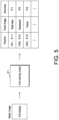
- FIG. 5 is a diagram showing an example of the false image detection using a first training model 31.
- the first training model 31 when one radar image displayed in R- ⁇ is input to the first training model 31, the first training model 31 outputs position data of false image and the accuracy thereof regarding the false image (first false image candidate) caused by a side lobe, a backwash, and a cloud.
- the position data of false image has area information.
- the first training model 31 can use semantic segmentation using deep learning, and can estimate a class label (for example, label 1: side lobe, label 2: backwash, and label 3: cloud) for all the pixels in the radar image.
- a plurality of pixels estimated to be a side lobe may be combined into one pixel group, and the center position of the pixel group may be set as the position of the side lobe.
- the pixel group can be treated as one false image. Further, the accuracy of the false image is obtained by averaging the accuracy of each pixel estimated to be a side lobe.
- the first training model 31 may use a fully convolutional network (FCN), an encoder-decoder structure model, YOLO (You Look Only Once), or the like.
- FIG. 6 is a diagram showing the first example of a false image.
- FIG. 6 shows a false image on a radar image.
- a false image caused by a side lobe is often displayed in a straight line in R- ⁇ display.
- the symbol ⁇ is the center of the false image and indicates the position of the false image.
- a false image caused by a backwash often appears distorted in a V-shape.
- the symbol O is the center of the false image and indicates the position of the false image.
- the symbol O may be attached to both V-shaped false images.
- a false image caused by a cloud is often relatively vague, and the area of the false image is often relatively large.
- the symbol X is the center of the false image and indicates the position of the false image. It should be noted that the false images shown in FIG. 6 are schematic illustrations, and may differ from the actual false images on a radar echo.
- the first training model 31 can be generated, for example, as follows. That is, in the case where one radar image displayed in R- ⁇ is input to the first training model 31, the first training model 31 may be generated so as to output the position data of a first false image candidate. Specifically, for the radar image displayed in R- ⁇ , an image in which a false image that is definitely confirmed to be a false image is annotated, as shown in FIG. 6 , is prepared as teacher data. Then, a large number of sets of radar images displayed in R- ⁇ and corresponding teacher data are collected as training data.
- the teacher data is, for example, radar images displayed in R- ⁇ , to which class labels are attached, such as label 1: side lobe, label 2: backwash, and label 3: cloud.
- the first training model 31 can be generated by adjusting the parameters of the first training model 31 based on the training data so that the value of the loss function, which is based on the position data of the false image output by the first training model 31 by inputting the radar image displayed in R- ⁇ to the first training model 31 and the position data of the false image included in the training data, is minimized.
- FIG. 7 is a diagram showing an example of the false image detection using a second training model 32.
- the second training model 32 outputs position data of false images and the accuracy thereof regarding the false image (second false image candidate) caused by reflection between own ship and another ship, reflection between another ship and another ship, and reflection between another ship and land.
- the time series (t1, t2, ..., tn) may be points in time each time the radar rotates, or may be points in time each time the radar rotates multiple times.
- the number of the time-series radar images may be determined as appropriate, such as 10, 20, 30, etc., for example.
- the second training model 32 can also utilize semantic segmentation using deep learning, and can estimate a class label (for example, label 1: reflection between own ship and another ship, label 2: reflection between another ship and another ship, and label 3: reflection between another ship and land) for all the pixels in the radar image.
- label 1 reflection between own ship and another ship
- label 2 reflection between another ship and another ship
- label 3 reflection between another ship and land
- a plurality of pixels estimated to be reflection between own ship and another ship may be combined into one pixel group, and the center position of the pixel group may be set as the position of the false image due to reflection between own ship and another ship.
- the pixel group can be treated as one false image.
- the accuracy of the false image is obtained by averaging the accuracy of each pixel estimated to be reflection between own ship and another ship.
- the second training model 32 may use a recurrent neural network (RNN)-based model, an ALSTM (Attention Long Short Term Memory), a Transformer, or the like.
- FIG. 8 is a diagram showing the second example of a false image.
- FIG. 8 displays a false image on a radar image.
- a false image caused by reflection between own ship and another ship is often displayed on an extension line between the own ship and another ship S1 in R- ⁇ display.
- the false image is generated due to reflection between the own ship and another ship S1.
- a false image caused by reflection between another ship and another ship is displayed on an extension line between the own ship and another ship S2.
- the false image is generated due to reflection between another ship S2 and another ship S1.
- a false image caused by reflection between another ship and land is displayed on an extension line between the own ship and another ship S3.
- the false image is generated due to reflection between another ship S3 and land.
- a false image represents a collection of pixels, and the center of the pixel group is the position of the false image. It should be noted that the false images shown in FIG. 8 are schematic illustrations, and may differ from the actual false images on a radar echo.
- the second training model 32 can be generated, for example, as follows. That is, in the case where time-series radar images displayed in R- ⁇ are input to the second training model 32, the second training model 32 may be generated so as to output the position data of a second false image candidate. Specifically, for the time-series radar images displayed in R- ⁇ , an image in which a false image that is definitely confirmed to be a false image is annotated, as shown in FIG. 8 , is prepared as teacher data.
- the teacher data is, for example, radar images displayed in R- ⁇ to which class labels are attached, such as label 1: reflection between own ship and another ship, label 2: reflection between another ship and another ship, and label 3: reflection between another ship and land.
- the second training model 32 can be generated by adjusting the parameters of the second training model 32 based on the training data so that the value of the loss function, which is based on the position data of the false image output by the second training model 32 by inputting the time-series radar images displayed in R- ⁇ to the second training model 32 and the position data of the false image included in the training data, is minimized.
- the radar apparatus 100 acquires image data including time-series radar images; inputs the acquired one radar image to the first training model 31 that outputs the position data of the first false image candidate in the case where one radar image is input, to acquire the position data of the first false image candidate; inputs the acquired time-series radar images to the second training model 32 that outputs the position data of the second false image candidate in the case where the time-series radar images are input, to acquire the position data of the second false image candidate; and detects a false image of a radar echo based on the acquired position data of the first false image candidate and the second false image candidate, thereby making it possible to recognize a false image on a radar echo.
- the AIS 41 is a communication device that can receive AIS data from another ship that exists around the own ship.
- the AIS data includes data such as identification code, ship name, position, course, ship speed, and destination.
- the AIS 41 outputs the AIS data to the target object identification unit 40.
- the present invention is not limited to AIS, and may use VDES (VHF Data Exchange System).
- the image sensor 42 can be configured with a visible light camera or an infrared camera, for example.
- the image sensor 42 photographs the outside of the ship and generates an image.
- the image sensor 42 may be installed, for example, on the bridge of the own ship to face toward the bow direction.
- the image sensor 42 may be configured to pan (swing in the horizontal direction), tilt (swing in the vertical direction), and zoom in response to an operation of the user.
- the image sensor 42 outputs image data to the target object identification unit 40.
- the target object identification unit 40 uses at least one of the AIS data output by the AIS 41 and the image data output by the image sensor 42 to identify a target object which is an object that actually exists (another ship, etc.).
- the position of the target object can be identified, for example, by the relative position in terms of distance and orientation from the own ship, or the absolute position in terms of latitude and longitude.
- the target object identification unit 40 may use a training model generated by machine learning.
- the training model can use an object detection model such as YOLO (You Only Look Once) or SSD (Single Shot Multibox Detector).
- the synthesis processing unit 50 makes a final determination as to whether the false image detected by the false image detection unit 30 is a false image or a real image (target object) rather than a false image, based on the detection result detected by the false image detection unit 30 and the identification result identified by the target object identification unit 40.
- the determination method performed by the synthesis processing unit 50 will be described below.
- FIG. 9 is a diagram showing an example of a final determination method for a false image.
- the detection results detected by the false image detection unit 30 are assumed to be false images F1 to F4, and the accuracy thereof is assumed to be P1 to P4, respectively.
- the accuracy P1 of the false image F1 exceeds a threshold value Th, and there is a high possibility that the false image F1 is a false image.
- the false image F 1 is finally determined to be a false image.
- the accuracy P2 exceeds the threshold value Th and there is a high possibility that the false image F2 is a false image, but since there is a target object identified by the target object identification unit 40 at the position of the false image, the false image F2 is finally determined to be a real image (not a false image).
- the accuracy P3 is below the threshold value Th, and there is a low possibility that the false image F3 is a false image. Since there is no target object identified by the target object identification unit 40 at the position of the false image, the false image F3 is determined to be neither a false image nor a real image. In this case, the false image F3 may be finally determined to be a false image.
- the accuracy P4 is below the threshold value Th, and there is a low possibility that the false image F4 is a false image. Further, since there is a target object identified by the target object identification unit 40 at the position of the false image, the false image F4 is finally determined to be a real image. It should be noted that the final determination method is not limited to the example shown in FIG. 9 .
- the radar apparatus 100 may acquire the detection result (identification result) at the sensor unit including at least one of the AIS 41 and the image sensor 42, and detect a false image on a radar echo based on the acquired detection result, the probability (accuracy) regarding the position data of the first false image candidate output by the first training model 31, and the probability regarding the position data of the second false image candidate output by the second training model, thereby making it possible to further improve the accuracy of detecting a false image.
- the display image generation unit 80 generates a display image to be displayed on the display device 90 based on the radar image generated by the radar image generation unit 20 and the final determination result of the synthesis processing unit 50.
- the display image includes, for example, an electronic nautical chart.
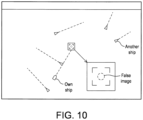
- FIG. 10 is a diagram showing an example of the display image.
- the display image displays an extensive nautical chart of the course direction of the own ship, and displays the positions and course directions of other ships around.
- the own ship navigates autonomously by specifying other ships approaching in the course direction of the own ship as avoidance targets.
- the symbol of the object determined to be a false image is indicated by a dashed circle, and the false image is excluded from the avoidance target. In this way, the radar apparatus 100 can differentiate the display mode depending on whether the radar echo has a false image.
- the false image is displayed as a dashed circle to be distinguished from other ships (target objects), but the present invention is not limited thereto, and the color of the false image may be changed. Furthermore, the false image may be deleted from the nautical chart and hidden. Thereby, it is easy to recognize the avoidance target.
- the display image generation unit 80 may differentiate the display mode of the false image based on the false image probability. For example, an object that is more likely to be a false image may be displayed in a brighter or more conspicuous color. Thereby, it is possible to visualize the certainty of the false image.
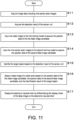
- FIG. 11 is a diagram showing an example of the processing procedure of the radar apparatus 100.
- the radar apparatus 100 acquires image data including time-series radar images (S11), and acquires the detection result of the sensor unit (S12).
- the radar apparatus 100 inputs one radar image to the first training model 31 to acquire the position data of the first false image candidate (S13).
- the first false image candidate includes a false image caused by at least one of a side lobe, a backwash, and a cloud.
- the radar apparatus 100 inputs the time-series radar images to the second training model 32 to acquire the position data of the second false image candidate (S14).
- the second false image candidate includes a false image caused by at least one of multiple reflections of the detection wave between the own ship and another ship, reflection between another ship and another ship, and reflection between another ship and land.
- the radar apparatus 100 identifies the target object based on the detection result of the sensor unit (S15).
- the radar apparatus 100 detects a false image of a radar echo based on the position data of the first false image candidate, the position data of the second false image candidate, and the identification result of the target object (S16).
- the determination method illustrated in FIG. 9 may be used.
- the processes of steps S11 to S15 may be repeated as appropriate.
- the radar apparatus 100 displays the electronic nautical chart with the display mode of the false image on the electronic nautical chart different from the display mode of the target object (S17), and ends the processing.
- All or some of the radar image generation unit 20, the false image detection unit 30, the target object identification unit 40, the synthesis processing unit 50, and the display image generation unit 80 of the radar apparatus 100 can also be implemented using a computer equipped with a CPU (processor), a RAM, etc.
- a computer program (recordable on a recording medium) that defines the processing procedure shown in FIG. 11 into the RAM provided in the computer and executing the computer program on the CPU (processor).
- the information processing method of this embodiment includes: acquiring image data that includes time-series radar images; inputting acquired one radar image to a first training model that outputs position data of a first false image candidate in response to one radar image being input, to acquire the position data of the first false image candidate; inputting acquired time-series radar images to a second training model that outputs position data of a second false image candidate in response to time-series radar images being input, to acquire the position data of the second false image candidate; and detecting a false image of a radar echo based on the acquired position data of the first false image candidate and the second false image candidate.
- the information processing method of this embodiment further includes: acquiring a detection result at a sensor unit that includes at least one of an AIS and an image sensor; and detecting the false image of the radar echo based on the acquired detection result, a probability regarding the position data of the first false image candidate output by the first training model, and a probability regarding the position data of the second false image candidate output by the second training model.
- the first false image candidate includes a false image caused by at least one of a side lobe, a backwash, and a cloud.
- the second false image candidate includes a false image caused by at least one of multiple reflections of a detection wave between an own ship and another ship, reflection between another ship and another ship, and reflection between another ship and land.
- the information processing method of this embodiment further includes differentiating a display mode according to whether the radar echo is a false image or not.
- the information processing method of this embodiment further includes differentiating a display mode of the false image based on a false image probability in response to the radar echo being a false image.
- the radar apparatus of this embodiment includes: a data acquisition unit which acquires image data that includes time-series radar images; a first acquisition unit which inputs acquired one radar image to a first training model that outputs position data of a first false image candidate in response to one radar image being input, to acquire the position data of the first false image candidate; a second acquisition unit which inputs acquired time-series radar images to a second training model that outputs position data of a second false image candidate in response to time-series radar images being input, to acquire the position data of the second false image candidate; and a detection unit which detects a false image of a radar echo based on the acquired position data of the first false image candidate and the second false image candidate.
- the computer program of this embodiment is configured to enable a computer to perform processes of: acquiring image data that includes time-series radar images; inputting acquired one radar image to a first training model that outputs position data of a first false image candidate in response to one radar image being input, to acquire the position data of the first false image candidate; inputting acquired time-series radar images to a second training model that outputs position data of a second false image candidate in response to time-series radar images being input, to acquire the position data of the second false image candidate; and detecting a false image of a radar echo based on the acquired position data of the first false image candidate and the second false image candidate.
Landscapes
- Engineering & Computer Science (AREA)
- Remote Sensing (AREA)
- Radar, Positioning & Navigation (AREA)
- Physics & Mathematics (AREA)
- Computer Networks & Wireless Communication (AREA)
- General Physics & Mathematics (AREA)
- Electromagnetism (AREA)
- Artificial Intelligence (AREA)
- Evolutionary Computation (AREA)
- Ocean & Marine Engineering (AREA)
- Radar Systems Or Details Thereof (AREA)
Abstract
Description
- The present invention relates to an information processing method, a radar apparatus, and a computer program.
- Navigation radar is an important apparatus that detects objects around one's own ship and provides information for safe and optimal avoidance actions.
Patent Document 1 discloses a technology in which an AIS apparatus of a ship equipped with an ARPA radar apparatus is connected to the ARPA radar apparatus via an interface, and which compares the received dynamic information of nearby ships and the radar symbol information acquired from the ARPA radar apparatus every moment and alerts the operator by using radar symbol information having no dynamic information recognized with a predetermined match as transmission stop warning information and using dynamic information having no radar symbol information recognized with a predetermined match as no situation report warning information. - [Patent Document 1]
Japanese Patent No. 3794641 - A radar emits radio waves around the own ship and observes the reflected waves to display information on the orientation and distance of an object as a radar echo. However, on the other hand, the radio waves emitted to an object may be reflected by another object, generating a false image that does not actually exist.
- The present invention has been made in view of such circumstances, and an object of the present invention is to provide an information processing method, a radar apparatus, and a computer program that can recognize a false image on a radar echo.
- The present application includes a plurality of means for solving the above problem, but as one example, an information processing method includes: acquiring image data that includes time-series radar images; inputting acquired one radar image to a first training model that outputs position data of a first false image candidate in response to one radar image being input, to acquire the position data of the first false image candidate; inputting acquired time-series radar images to a second training model that outputs position data of a second false image candidate in response to time-series radar images being input, to acquire the position data of the second false image candidate; and detecting a false image of a radar echo based on the acquired position data of the first false image candidate and the second false image candidate.
- According to the present invention, it is possible to recognize a false image on a radar echo.
-
-
FIG. 1 is a diagram showing an example of the configuration of the radar apparatus. -
FIG. 2 is a diagram showing an example of the echo signal. -
FIG. 3 is a diagram showing an example of the radar image. -
FIG. 4 is a diagram showing an example of the occurrence of the false image. -
FIG. 5 is a diagram showing an example of the false image detection using the first training model. -
FIG. 6 is a diagram showing the first example of the false image. -
FIG. 7 is a diagram showing an example of the false image detection using the second training model. -
FIG. 8 is a diagram showing the second example of the false image. -
FIG. 9 is a diagram showing an example of the final determination method for the false image. -
FIG. 10 is a diagram showing an example of the display image. -
FIG. 11 is a diagram showing an example of the processing procedure of the radar apparatus. - Embodiments of the present invention will be described hereinafter.
FIG. 1 is a diagram showing an example of the configuration of aradar apparatus 100. Theradar apparatus 100 includes anantenna unit 10, a radarimage generation unit 20, a falseimage detection unit 30, a targetobject identification unit 40, an AIS (Automatic Identification System) 41, animage sensor 42, asynthesis processing unit 50, a displayimage generation unit 80, and adisplay device 90. Nevertheless, the targetobject identification unit 40, the AIS (Automatic Identification System) 41, and theimage sensor 42 may be configured as devices separate from theradar apparatus 100. Theantenna unit 10 includes anantenna 11, areception unit 12, and an A/D conversion unit 13. The falseimage detection unit 30 includes afirst training model 31 and asecond training model 32. The AIS 41 and theimage sensor 42 are also collectively referred to as a sensor unit. - The
antenna 11 is a radar antenna that is capable of transmitting highly directional pulsed radio waves (transmission waves). Theantenna 11 is configured to receive reflected waves from an object such as a target object. Theradar apparatus 100 measures the time from when pulsed radio waves are transmitted until when reflected waves are received. Thereby, theradar apparatus 100 can detect the distance to the target object. Theantenna 11 is configured to be rotatable 360° on a horizontal plane. Theantenna 11 is configured to repeatedly transmit and receive radio waves at predetermined intervals while changing the transmission direction of the pulsed radio waves (while changing the antenna angle). Thereby, theradar apparatus 100 can detect a target object on a plane around the own ship over 360°. -
FIG. 2 is a diagram showing an example of an echo signal. As shown inFIG. 2 , theradar apparatus 100 on the own ship transmits detection waves in a certain direction and receives reflected waves. When the reflected waves are received, the antenna rotates to repeat the same process of transmitting detection waves and receiving reflected waves. The same process is repeated over 360 degrees around the own ship. One image is generated after the antenna rotates 360 degrees. When a received signal (echo signal) in one direction is extracted, the strength of the received signal is obtained according to the distance from the own ship. It is known that an object exists at a distance where the signal strength is high. It is assumed that a target object is an object that actually exists such as another ship, and a false image is an object that does not actually exist. - The
reception unit 12 detects and amplifies the echo signal obtained from the reflected waves received by theantenna 11, and outputs the amplified echo signal to the A/D conversion unit 13. The A/D conversion unit 13 samples the echo signal in analog form and converts the echo signal into digital data (echo data) composed of multiple bits. Here, the echo data includes data specifying the strength (signal level) of the echo signal obtained from the reflected waves received by theantenna 11. The A/D conversion unit 13 outputs the echo data to the radarimage generation unit 20. - The radar
image generation unit 20 generates a radar image based on the echo data output from the A/D conversion unit 13. -
FIG. 3 is a diagram showing an example of the radar image. A ofFIG. 3 is a radar image displayed in PPI (Plane Position Indicator), and is a radar image over 360 degrees in the horizontal direction centered on the own ship position. The radarimage generation unit 20 includes an R-θ conversion unit, and can convert a radar image displayed in PPI into a radar image displayed in R-θ (Range theta) as shown in B ofFIG. 3 . In the radar image displayed in R-θ, the vertical axis shows the distance from the own ship, and the horizontal axis shows the orientation (from 0 to 360 degrees). The radarimage generation unit 20 outputs the radar image displayed in R-θ to the falseimage detecting unit 30. In addition, a radar image displayed in R-θ (Range theta) may be generated from the echo data output from the A/D conversion unit 13 without generating a radar image displayed in PPI. - Next, the mechanism by which a false image occurs will be explained.
-
FIG. 4 is a diagram showing an example of the occurrence of a false image. A ofFIG. 4 shows how a false image occurs between the own ship and another ship. When the radio waves emitted from the antenna on the own ship are reflected by another ship, the reflected waves are reflected by the own ship, and the reflected waves are reflected by another ship and received by the antenna, on the radar echo, an object exists at a position indicated by the symbol F1. However, since there is actually no target object (another ship), a false image is generated at the position of the symbol F1. Similarly, in the case where reflection is repeated twice between the own ship and another ship, a false image is generated at a position of the symbol F2. Thus, false images occur due to the reflection (including multiple reflections) of radio waves between the own ship and another ship. - B of
FIG. 4 shows how a false image occurs between another ship and another ship. As shown in B ofFIG. 4 , another ship A and another ship B exist around the own ship. When the radio waves emitted from the antenna on the own ship are reflected by another ship A, the reflected waves are reflected by the own ship B, and the reflected waves are reflected by another ship A and received by the antenna, on the radar echo, an object exists at a position indicated by the symbol F3. However, since there is actually no target object (another ship), a false image is generated at the position of the symbol F3. Thus, false images occur due to the reflection of radio waves between another ship and another ship. - C of
FIG. 4 shows how a false image occurs between another ship and land. As shown in C ofFIG. 4 , another ship A and land (including, for example, a structure or the like on an island) exist around the own ship. When the radio waves emitted from the antenna on the own ship are reflected by another ship A, the reflected waves are reflected by the structure on the land, and the reflected waves are reflected by another ship A and received by the antenna, on the radar echo, an object exists at a position indicated by the symbol F4. However, since there is actually no target object (another ship), a false image is generated at the position of the symbol F4. Thus, false images occur due to the reflection of radio waves between another ship and land. - False images are also caused by a side lobe, a backwash, a cloud, etc. The side lobe is a portion where the radio wave strength is weaker than the main lobe where the strength of the radio waves emitted from the antenna is maximum, and is a leakage radio wave that is emitted in a direction different from the direction of the main lobe by, for example, 30 to 45 degrees. The backwash is a wave that occurs behind a ship when sailing. Generally, radar echoes of a backwash and a cloud are not false images, but here they are treated as a type of false image as radar echoes that are not subject to avoidance.
- Next, a method for detecting a false image will be explained.
-
FIG. 5 is a diagram showing an example of the false image detection using afirst training model 31. As shown inFIG. 5 , when one radar image displayed in R-θ is input to thefirst training model 31, thefirst training model 31 outputs position data of false image and the accuracy thereof regarding the false image (first false image candidate) caused by a side lobe, a backwash, and a cloud. The position data of false image has area information. Thefirst training model 31 can use semantic segmentation using deep learning, and can estimate a class label (for example, label 1: side lobe, label 2: backwash, and label 3: cloud) for all the pixels in the radar image. For example, a plurality of pixels estimated to be a side lobe may be combined into one pixel group, and the center position of the pixel group may be set as the position of the side lobe. For false images on a radar echo, the pixel group can be treated as one false image. Further, the accuracy of the false image is obtained by averaging the accuracy of each pixel estimated to be a side lobe. Thefirst training model 31 may use a fully convolutional network (FCN), an encoder-decoder structure model, YOLO (You Look Only Once), or the like. -
FIG. 6 is a diagram showing the first example of a false image.FIG. 6 shows a false image on a radar image. As shown inFIG. 6 , a false image caused by a side lobe is often displayed in a straight line in R-θ display. The symbol Δ is the center of the false image and indicates the position of the false image. A false image caused by a backwash often appears distorted in a V-shape. The symbol O is the center of the false image and indicates the position of the false image. In addition, the symbol O may be attached to both V-shaped false images. A false image caused by a cloud is often relatively vague, and the area of the false image is often relatively large. The symbol X is the center of the false image and indicates the position of the false image. It should be noted that the false images shown inFIG. 6 are schematic illustrations, and may differ from the actual false images on a radar echo. - The
first training model 31 can be generated, for example, as follows. That is, in the case where one radar image displayed in R-θ is input to thefirst training model 31, thefirst training model 31 may be generated so as to output the position data of a first false image candidate. Specifically, for the radar image displayed in R-θ, an image in which a false image that is definitely confirmed to be a false image is annotated, as shown inFIG. 6 , is prepared as teacher data. Then, a large number of sets of radar images displayed in R-θ and corresponding teacher data are collected as training data. The teacher data is, for example, radar images displayed in R-θ, to which class labels are attached, such as label 1: side lobe, label 2: backwash, and label 3: cloud. Thefirst training model 31 can be generated by adjusting the parameters of thefirst training model 31 based on the training data so that the value of the loss function, which is based on the position data of the false image output by thefirst training model 31 by inputting the radar image displayed in R-θ to thefirst training model 31 and the position data of the false image included in the training data, is minimized. -
FIG. 7 is a diagram showing an example of the false image detection using asecond training model 32. As shown inFIG. 7 , when radar images of a time series (t1, t2, ..., tn) displayed in R-θ are input to thesecond training model 32, thesecond training model 32 outputs position data of false images and the accuracy thereof regarding the false image (second false image candidate) caused by reflection between own ship and another ship, reflection between another ship and another ship, and reflection between another ship and land. When the radar rotates once, one radar image displayed in R-θ is generated. The time series (t1, t2, ..., tn) may be points in time each time the radar rotates, or may be points in time each time the radar rotates multiple times. The number of the time-series radar images may be determined as appropriate, such as 10, 20, 30, etc., for example. Similarly to thefirst training model 31, thesecond training model 32 can also utilize semantic segmentation using deep learning, and can estimate a class label (for example, label 1: reflection between own ship and another ship, label 2: reflection between another ship and another ship, and label 3: reflection between another ship and land) for all the pixels in the radar image. For example, a plurality of pixels estimated to be reflection between own ship and another ship may be combined into one pixel group, and the center position of the pixel group may be set as the position of the false image due to reflection between own ship and another ship. For false images on a radar echo, the pixel group can be treated as one false image. Further, the accuracy of the false image is obtained by averaging the accuracy of each pixel estimated to be reflection between own ship and another ship. By inputting the time-series radar images, in thesecond training model 32, it is possible to take into consideration the temporal behaviors of the positional relationships between own ship and another ship, between another ship and another ship, and between another ship and land, and to accurately detect false images caused by reflection between own ship and another ship, reflection between another ship and another ship, and reflection between another ship and land. Thesecond training model 32 may use a recurrent neural network (RNN)-based model, an ALSTM (Attention Long Short Term Memory), a Transformer, or the like. -
FIG. 8 is a diagram showing the second example of a false image.FIG. 8 displays a false image on a radar image. As shown inFIG. 8 , a false image caused by reflection between own ship and another ship is often displayed on an extension line between the own ship and another ship S1 in R-θ display. In this case, the false image is generated due to reflection between the own ship and another ship S1. A false image caused by reflection between another ship and another ship is displayed on an extension line between the own ship and another ship S2. In this case, the false image is generated due to reflection between another ship S2 and another ship S1. A false image caused by reflection between another ship and land is displayed on an extension line between the own ship and another ship S3. In this case, the false image is generated due to reflection between another ship S3 and land. A false image represents a collection of pixels, and the center of the pixel group is the position of the false image. It should be noted that the false images shown inFIG. 8 are schematic illustrations, and may differ from the actual false images on a radar echo. - The
second training model 32 can be generated, for example, as follows. That is, in the case where time-series radar images displayed in R-θ are input to thesecond training model 32, thesecond training model 32 may be generated so as to output the position data of a second false image candidate. Specifically, for the time-series radar images displayed in R-θ, an image in which a false image that is definitely confirmed to be a false image is annotated, as shown inFIG. 8 , is prepared as teacher data. The teacher data is, for example, radar images displayed in R-θ to which class labels are attached, such as label 1: reflection between own ship and another ship, label 2: reflection between another ship and another ship, and label 3: reflection between another ship and land. Then, a large number of sets of time-series radar images displayed in R-θ and corresponding teacher data are collected as training data. Thesecond training model 32 can be generated by adjusting the parameters of thesecond training model 32 based on the training data so that the value of the loss function, which is based on the position data of the false image output by thesecond training model 32 by inputting the time-series radar images displayed in R-θ to thesecond training model 32 and the position data of the false image included in the training data, is minimized. - As described above, the
radar apparatus 100 acquires image data including time-series radar images; inputs the acquired one radar image to thefirst training model 31 that outputs the position data of the first false image candidate in the case where one radar image is input, to acquire the position data of the first false image candidate; inputs the acquired time-series radar images to thesecond training model 32 that outputs the position data of the second false image candidate in the case where the time-series radar images are input, to acquire the position data of the second false image candidate; and detects a false image of a radar echo based on the acquired position data of the first false image candidate and the second false image candidate, thereby making it possible to recognize a false image on a radar echo. - The
AIS 41 is a communication device that can receive AIS data from another ship that exists around the own ship. The AIS data includes data such as identification code, ship name, position, course, ship speed, and destination. TheAIS 41 outputs the AIS data to the targetobject identification unit 40. It should be noted that the present invention is not limited to AIS, and may use VDES (VHF Data Exchange System). - The
image sensor 42 can be configured with a visible light camera or an infrared camera, for example. Theimage sensor 42 photographs the outside of the ship and generates an image. Theimage sensor 42 may be installed, for example, on the bridge of the own ship to face toward the bow direction. Theimage sensor 42 may be configured to pan (swing in the horizontal direction), tilt (swing in the vertical direction), and zoom in response to an operation of the user. Theimage sensor 42 outputs image data to the targetobject identification unit 40. - The target
object identification unit 40 uses at least one of the AIS data output by theAIS 41 and the image data output by theimage sensor 42 to identify a target object which is an object that actually exists (another ship, etc.). The position of the target object can be identified, for example, by the relative position in terms of distance and orientation from the own ship, or the absolute position in terms of latitude and longitude. In the case of identifying a target object based on image data, the targetobject identification unit 40 may use a training model generated by machine learning. In this case, the training model can use an object detection model such as YOLO (You Only Look Once) or SSD (Single Shot Multibox Detector). - The
synthesis processing unit 50 makes a final determination as to whether the false image detected by the falseimage detection unit 30 is a false image or a real image (target object) rather than a false image, based on the detection result detected by the falseimage detection unit 30 and the identification result identified by the targetobject identification unit 40. The determination method performed by thesynthesis processing unit 50 will be described below. -
FIG. 9 is a diagram showing an example of a final determination method for a false image. The detection results detected by the falseimage detection unit 30 are assumed to be false images F1 to F4, and the accuracy thereof is assumed to be P1 to P4, respectively. As shown inFIG. 9 , the accuracy P1 of the false image F1 exceeds a threshold value Th, and there is a high possibility that the false image F1 is a false image. Further, since there is no target object identified by the targetobject identification unit 40 at the position of the false image, thefalse image F 1 is finally determined to be a false image. As for the false image F2, the accuracy P2 exceeds the threshold value Th and there is a high possibility that the false image F2 is a false image, but since there is a target object identified by the targetobject identification unit 40 at the position of the false image, the false image F2 is finally determined to be a real image (not a false image). As for the false image F3, the accuracy P3 is below the threshold value Th, and there is a low possibility that the false image F3 is a false image. Since there is no target object identified by the targetobject identification unit 40 at the position of the false image, the false image F3 is determined to be neither a false image nor a real image. In this case, the false image F3 may be finally determined to be a false image. As for the false image F4, the accuracy P4 is below the threshold value Th, and there is a low possibility that the false image F4 is a false image. Further, since there is a target object identified by the targetobject identification unit 40 at the position of the false image, the false image F4 is finally determined to be a real image. It should be noted that the final determination method is not limited to the example shown inFIG. 9 . - As described above, the
radar apparatus 100 may acquire the detection result (identification result) at the sensor unit including at least one of theAIS 41 and theimage sensor 42, and detect a false image on a radar echo based on the acquired detection result, the probability (accuracy) regarding the position data of the first false image candidate output by thefirst training model 31, and the probability regarding the position data of the second false image candidate output by the second training model, thereby making it possible to further improve the accuracy of detecting a false image. - The display
image generation unit 80 generates a display image to be displayed on thedisplay device 90 based on the radar image generated by the radarimage generation unit 20 and the final determination result of thesynthesis processing unit 50. The display image includes, for example, an electronic nautical chart. -
FIG. 10 is a diagram showing an example of the display image. As shown inFIG. 10 , the display image displays an extensive nautical chart of the course direction of the own ship, and displays the positions and course directions of other ships around. In order to avoid coming close to other ships, the own ship navigates autonomously by specifying other ships approaching in the course direction of the own ship as avoidance targets. In the drawing, the symbol of the object determined to be a false image is indicated by a dashed circle, and the false image is excluded from the avoidance target. In this way, theradar apparatus 100 can differentiate the display mode depending on whether the radar echo has a false image. In the illustrated example, the false image is displayed as a dashed circle to be distinguished from other ships (target objects), but the present invention is not limited thereto, and the color of the false image may be changed. Furthermore, the false image may be deleted from the nautical chart and hidden. Thereby, it is easy to recognize the avoidance target. In addition, in the case where the radar echo has a false image, the displayimage generation unit 80 may differentiate the display mode of the false image based on the false image probability. For example, an object that is more likely to be a false image may be displayed in a brighter or more conspicuous color. Thereby, it is possible to visualize the certainty of the false image. -
FIG. 11 is a diagram showing an example of the processing procedure of theradar apparatus 100. Theradar apparatus 100 acquires image data including time-series radar images (S11), and acquires the detection result of the sensor unit (S12). Theradar apparatus 100 inputs one radar image to thefirst training model 31 to acquire the position data of the first false image candidate (S13). The first false image candidate includes a false image caused by at least one of a side lobe, a backwash, and a cloud. - The
radar apparatus 100 inputs the time-series radar images to thesecond training model 32 to acquire the position data of the second false image candidate (S14). The second false image candidate includes a false image caused by at least one of multiple reflections of the detection wave between the own ship and another ship, reflection between another ship and another ship, and reflection between another ship and land. Theradar apparatus 100 identifies the target object based on the detection result of the sensor unit (S15). - The
radar apparatus 100 detects a false image of a radar echo based on the position data of the first false image candidate, the position data of the second false image candidate, and the identification result of the target object (S16). In step 16, the determination method illustrated inFIG. 9 may be used. Before performing the process of step S16, the processes of steps S11 to S15 may be repeated as appropriate. Theradar apparatus 100 displays the electronic nautical chart with the display mode of the false image on the electronic nautical chart different from the display mode of the target object (S17), and ends the processing. - All or some of the radar
image generation unit 20, the falseimage detection unit 30, the targetobject identification unit 40, thesynthesis processing unit 50, and the displayimage generation unit 80 of theradar apparatus 100 can also be implemented using a computer equipped with a CPU (processor), a RAM, etc. Each of the above units of theradar apparatus 100 can be implemented on a computer by loading a computer program (recordable on a recording medium) that defines the processing procedure shown inFIG. 11 into the RAM provided in the computer and executing the computer program on the CPU (processor). - The information processing method of this embodiment includes: acquiring image data that includes time-series radar images; inputting acquired one radar image to a first training model that outputs position data of a first false image candidate in response to one radar image being input, to acquire the position data of the first false image candidate; inputting acquired time-series radar images to a second training model that outputs position data of a second false image candidate in response to time-series radar images being input, to acquire the position data of the second false image candidate; and detecting a false image of a radar echo based on the acquired position data of the first false image candidate and the second false image candidate.
- The information processing method of this embodiment further includes: acquiring a detection result at a sensor unit that includes at least one of an AIS and an image sensor; and detecting the false image of the radar echo based on the acquired detection result, a probability regarding the position data of the first false image candidate output by the first training model, and a probability regarding the position data of the second false image candidate output by the second training model.
- In the information processing method of this embodiment, the first false image candidate includes a false image caused by at least one of a side lobe, a backwash, and a cloud.
- In the information processing method of this embodiment, the second false image candidate includes a false image caused by at least one of multiple reflections of a detection wave between an own ship and another ship, reflection between another ship and another ship, and reflection between another ship and land.
- The information processing method of this embodiment further includes differentiating a display mode according to whether the radar echo is a false image or not.
- The information processing method of this embodiment further includes differentiating a display mode of the false image based on a false image probability in response to the radar echo being a false image.
- The radar apparatus of this embodiment includes: a data acquisition unit which acquires image data that includes time-series radar images; a first acquisition unit which inputs acquired one radar image to a first training model that outputs position data of a first false image candidate in response to one radar image being input, to acquire the position data of the first false image candidate; a second acquisition unit which inputs acquired time-series radar images to a second training model that outputs position data of a second false image candidate in response to time-series radar images being input, to acquire the position data of the second false image candidate; and a detection unit which detects a false image of a radar echo based on the acquired position data of the first false image candidate and the second false image candidate.
- The computer program of this embodiment is configured to enable a computer to perform processes of: acquiring image data that includes time-series radar images; inputting acquired one radar image to a first training model that outputs position data of a first false image candidate in response to one radar image being input, to acquire the position data of the first false image candidate; inputting acquired time-series radar images to a second training model that outputs position data of a second false image candidate in response to time-series radar images being input, to acquire the position data of the second false image candidate; and detecting a false image of a radar echo based on the acquired position data of the first false image candidate and the second false image candidate.
-
- 10 antenna unit
- 11 antenna
- 12 reception unit
- 13 A/D conversion unit
- 20 radar image generation unit
- 30 false image detection unit
- 31 first training model
- 32 second training model
- 40 target object identification unit
- 50 synthesis processing unit
- 80 display image generation unit
- 90 display device
Claims (8)
- An information processing method, comprising:acquiring image data that comprises time-series radar images;inputting acquired one radar image to a first training model that outputs position data of a first false image candidate in response to one radar image being input, to acquire the position data of the first false image candidate;inputting acquired time-series radar images to a second training model that outputs position data of a second false image candidate in response to time-series radar images being input, to acquire the position data of the second false image candidate; anddetecting a false image of a radar echo based on the acquired position data of the first false image candidate and the second false image candidate.
- The information processing method according to claim 1, further comprising:acquiring a detection result at a sensor unit that comprises at least one of an AIS and an image sensor; anddetecting the false image of the radar echo based on the acquired detection result, a probability regarding the position data of the first false image candidate output by the first training model, and a probability regarding the position data of the second false image candidate output by the second training model.
- The information processing method according to claim 1 or 2, wherein the first false image candidate comprises a false image caused by at least one of a side lobe, a backwash, and a cloud.
- The information processing method according to any one of claims 1 to 3, wherein the second false image candidate comprises a false image caused by at least one of multiple reflections of a detection wave between an own ship and another ship, reflection between another ship and another ship, and reflection between another ship and land.
- The information processing method according to any one of claims 1 to 4, further comprising differentiating a display mode according to whether the radar echo is a false image or not.
- The information processing method according to any one of claims 1 to 5, further comprising differentiating a display mode of the false image based on a false image probability in response to the radar echo being a false image.
- A radar apparatus, comprising:a data acquisition unit configured to acquire image data that comprises time-series radar images;a first acquisition unit configured to input acquired one radar image to a first training model that outputs position data of a first false image candidate in response to one radar image being input, to acquire the position data of the first false image candidate;a second acquisition unit configured to input acquired time-series radar images to a second training model that outputs position data of a second false image candidate in response to time-series radar images being input, to acquire the position data of the second false image candidate; anda detection unit configured to detect a false image of a radar echo based on the acquired position data of the first false image candidate and the second false image candidate.
- A computer program, configured to enable a computer to perform processes of:acquiring image data that comprises time-series radar images;inputting acquired one radar image to a first training model that outputs position data of a first false image candidate in response to one radar image being input, to acquire the position data of the first false image candidate;inputting acquired time-series radar images to a second training model that outputs position data of a second false image candidate in response to time-series radar images being input, to acquire the position data of the second false image candidate; anddetecting a false image of a radar echo based on the acquired position data of the first false image candidate and the second false image candidate.
Applications Claiming Priority (2)
| Application Number | Priority Date | Filing Date | Title |
|---|---|---|---|
| JP2021196344 | 2021-12-02 | ||
| PCT/JP2022/015561 WO2023100390A1 (en) | 2021-12-02 | 2022-03-29 | Information processing method, radar apparatus, and computer program |
Publications (2)
| Publication Number | Publication Date |
|---|---|
| EP4443190A1 true EP4443190A1 (en) | 2024-10-09 |
| EP4443190A4 EP4443190A4 (en) | 2025-11-19 |
Family
ID=86611756
Family Applications (1)
| Application Number | Title | Priority Date | Filing Date |
|---|---|---|---|
| EP22900826.3A Pending EP4443190A4 (en) | 2021-12-02 | 2022-03-29 | INFORMATION PROCESSING METHOD, RADAR DEVICE AND COMPUTER PROGRAM |
Country Status (5)
| Country | Link |
|---|---|
| US (1) | US20240310483A1 (en) |
| EP (1) | EP4443190A4 (en) |
| JP (1) | JPWO2023100390A1 (en) |
| CN (1) | CN118318180A (en) |
| WO (1) | WO2023100390A1 (en) |
Families Citing this family (2)
| Publication number | Priority date | Publication date | Assignee | Title |
|---|---|---|---|---|
| CN118537562A (en) * | 2024-06-17 | 2024-08-23 | 西安电子科技大学 | A radar multiple reflection interference echo suppression method based on semantic segmentation |
| CN121121126B (en) * | 2025-11-12 | 2026-03-17 | 广东海洋大学深圳研究院 | A Ship Target Segmentation Method Based on an Improved Whale Optimization Algorithm |
Family Cites Families (8)
| Publication number | Priority date | Publication date | Assignee | Title |
|---|---|---|---|---|
| JP3794641B2 (en) | 2003-11-10 | 2006-07-05 | 海洋電子工業株式会社 | Method for improving the reliability of AIS transmission / reception information |
| JP6611796B2 (en) * | 2015-04-28 | 2019-11-27 | 古野電気株式会社 | Signal processing apparatus and radar apparatus |
| JP2019074478A (en) * | 2017-10-18 | 2019-05-16 | 沖電気工業株式会社 | Identification device, identification method and program |
| KR102376709B1 (en) * | 2019-01-30 | 2022-03-18 | 바이두닷컴 타임즈 테크놀로지(베이징) 컴퍼니 리미티드 | Point cloud registration system for autonomous vehicles |
| US11373064B2 (en) * | 2019-07-22 | 2022-06-28 | Raytheon Company | Cross-modality automatic target recognition |
| JP7371907B2 (en) * | 2019-12-25 | 2023-10-31 | 知洋 下川部 | Management server in ship navigation support system, ship navigation support method, and ship navigation support program |
| WO2021161502A1 (en) * | 2020-02-14 | 2021-08-19 | 日本電気株式会社 | Learning device, learning method, recording medium, and radar device |
| DK180729B1 (en) * | 2020-04-06 | 2022-02-08 | Robin Radar Facilities Bv | System for processing radar data representing intensity values of received power of reflected radar wave signals |
-
2022
- 2022-03-29 EP EP22900826.3A patent/EP4443190A4/en active Pending
- 2022-03-29 JP JP2023564730A patent/JPWO2023100390A1/ja active Pending
- 2022-03-29 WO PCT/JP2022/015561 patent/WO2023100390A1/en not_active Ceased
- 2022-03-29 CN CN202280079051.0A patent/CN118318180A/en active Pending
-
2024
- 2024-05-26 US US18/674,902 patent/US20240310483A1/en active Pending
Also Published As
| Publication number | Publication date |
|---|---|
| CN118318180A (en) | 2024-07-09 |
| JPWO2023100390A1 (en) | 2023-06-08 |
| EP4443190A4 (en) | 2025-11-19 |
| US20240310483A1 (en) | 2024-09-19 |
| WO2023100390A1 (en) | 2023-06-08 |
Similar Documents
| Publication | Publication Date | Title |
|---|---|---|
| US6650275B1 (en) | Image processing for hazard recognition in on-board weather radar | |
| EP4082890A1 (en) | Administrative server in ship navigation assistance system, ship navigation assistance method, and ship navigation assistance program | |
| CN101038168B (en) | mobile display device | |
| US12461538B2 (en) | Small unmanned aerial systems detection and classification using multi-modal deep neural networks | |
| CN110175186A (en) | A kind of intelligent ship environmental threat target apperception system and method | |
| US20240310483A1 (en) | Information processing method, radar apparatus, and recording medium | |
| EP3290947B1 (en) | Signal processing device and radar device | |
| JP7184101B2 (en) | Ship behavior analysis device, ship behavior analysis method and program | |
| CN113156417B (en) | Anti-unmanned aerial vehicle detection system, method and radar equipment | |
| EP4363877B1 (en) | Methods and systems for detecting vessels | |
| US4438438A (en) | Method for displaying a battle situation | |
| JP6762726B2 (en) | Radar device and target tracking method | |
| US20190137624A1 (en) | Signal processing device and radar device | |
| JPH1164497A (en) | Radar equipment | |
| KR102558387B1 (en) | System and method for providing motion information and size information of ship based on real-time radar image | |
| CN111323756B (en) | Marine radar target detection method and device based on deep learning | |
| WO2023095118A1 (en) | Dead reckoning-based analysis of fabricated maritime data | |
| JP6732900B2 (en) | Signal processing device and radar device | |
| CN111323757B (en) | Target detection method and device for marine radar | |
| KR20210111703A (en) | Pulse integration method for providing high resolution radar image and sea surveillance radar system using the same | |
| KR102479959B1 (en) | Artificial intelligence based integrated alert method and object monitoring device | |
| EP3435112A1 (en) | Radar device and wake display method | |
| WO2023095116A1 (en) | Identifying fabricated maritime signals | |
| US20230110788A1 (en) | Learning device, learning method, recording medium, and radar device | |
| Ponzini et al. | Marine obstacles multi-modal detection, classification and tracking via camera-lidar late fusion |
Legal Events
| Date | Code | Title | Description |
|---|---|---|---|
| STAA | Information on the status of an ep patent application or granted ep patent |
Free format text: STATUS: THE INTERNATIONAL PUBLICATION HAS BEEN MADE |
|
| PUAI | Public reference made under article 153(3) epc to a published international application that has entered the european phase |
Free format text: ORIGINAL CODE: 0009012 |
|
| STAA | Information on the status of an ep patent application or granted ep patent |
Free format text: STATUS: REQUEST FOR EXAMINATION WAS MADE |
|
| 17P | Request for examination filed |
Effective date: 20240617 |
|
| AK | Designated contracting states |
Kind code of ref document: A1 Designated state(s): AL AT BE BG CH CY CZ DE DK EE ES FI FR GB GR HR HU IE IS IT LI LT LU LV MC MK MT NL NO PL PT RO RS SE SI SK SM TR |
|
| DAV | Request for validation of the european patent (deleted) | ||
| DAX | Request for extension of the european patent (deleted) | ||
| A4 | Supplementary search report drawn up and despatched |
Effective date: 20251022 |
|
| RIC1 | Information provided on ipc code assigned before grant |
Ipc: G01S 7/03 20060101AFI20251016BHEP Ipc: G01S 7/10 20060101ALI20251016BHEP Ipc: G01S 7/32 20060101ALI20251016BHEP Ipc: G01S 13/937 20200101ALI20251016BHEP Ipc: G01S 7/41 20060101ALI20251016BHEP Ipc: G01S 13/86 20060101ALI20251016BHEP Ipc: G01S 7/292 20060101ALI20251016BHEP |