EP4443140A1 - Optical sensor - Google Patents
Optical sensor Download PDFInfo
- Publication number
- EP4443140A1 EP4443140A1 EP24167723.6A EP24167723A EP4443140A1 EP 4443140 A1 EP4443140 A1 EP 4443140A1 EP 24167723 A EP24167723 A EP 24167723A EP 4443140 A1 EP4443140 A1 EP 4443140A1
- Authority
- EP
- European Patent Office
- Prior art keywords
- pretreat
- mixture
- light signal
- processing system
- properties
- Prior art date
- Legal status (The legal status is an assumption and is not a legal conclusion. Google has not performed a legal analysis and makes no representation as to the accuracy of the status listed.)
- Granted
Links
Images

Classifications
-
- G—PHYSICS
- G01—MEASURING; TESTING
- G01N—INVESTIGATING OR ANALYSING MATERIALS BY DETERMINING THEIR CHEMICAL OR PHYSICAL PROPERTIES
- G01N21/00—Investigating or analysing materials by the use of optical means, i.e. using sub-millimetre waves, infrared, visible or ultraviolet light
- G01N21/84—Systems specially adapted for particular applications
- G01N21/85—Investigating moving fluids or granular solids
- G01N21/8507—Probe photometers, i.e. with optical measuring part dipped into fluid sample
-
- G—PHYSICS
- G01—MEASURING; TESTING
- G01N—INVESTIGATING OR ANALYSING MATERIALS BY DETERMINING THEIR CHEMICAL OR PHYSICAL PROPERTIES
- G01N21/00—Investigating or analysing materials by the use of optical means, i.e. using sub-millimetre waves, infrared, visible or ultraviolet light
- G01N21/17—Systems in which incident light is modified in accordance with the properties of the material investigated
- G01N21/25—Colour; Spectral properties, i.e. comparison of effect of material on the light at two or more different wavelengths or wavelength bands
- G01N21/31—Investigating relative effect of material at wavelengths characteristic of specific elements or molecules, e.g. atomic absorption spectrometry
- G01N21/314—Investigating relative effect of material at wavelengths characteristic of specific elements or molecules, e.g. atomic absorption spectrometry with comparison of measurements at specific and non-specific wavelengths
-
- B—PERFORMING OPERATIONS; TRANSPORTING
- B64—AIRCRAFT; AVIATION; COSMONAUTICS
- B64G—COSMONAUTICS; VEHICLES OR EQUIPMENT THEREFOR
- B64G1/00—Cosmonautic vehicles
- B64G1/22—Parts of, or equipment specially adapted for fitting in or to, cosmonautic vehicles
- B64G1/46—Arrangements or adaptations of devices for control of environment or living conditions
-
- C—CHEMISTRY; METALLURGY
- C02—TREATMENT OF WATER, WASTE WATER, SEWAGE, OR SLUDGE
- C02F—TREATMENT OF WATER, WASTE WATER, SEWAGE, OR SLUDGE
- C02F1/00—Treatment of water, waste water, or sewage
- C02F1/008—Control or steering systems not provided for elsewhere in subclass C02F
-
- G—PHYSICS
- G01—MEASURING; TESTING
- G01N—INVESTIGATING OR ANALYSING MATERIALS BY DETERMINING THEIR CHEMICAL OR PHYSICAL PROPERTIES
- G01N21/00—Investigating or analysing materials by the use of optical means, i.e. using sub-millimetre waves, infrared, visible or ultraviolet light
- G01N21/17—Systems in which incident light is modified in accordance with the properties of the material investigated
- G01N21/25—Colour; Spectral properties, i.e. comparison of effect of material on the light at two or more different wavelengths or wavelength bands
- G01N21/255—Details, e.g. use of specially adapted sources, lighting or optical systems
-
- G—PHYSICS
- G01—MEASURING; TESTING
- G01N—INVESTIGATING OR ANALYSING MATERIALS BY DETERMINING THEIR CHEMICAL OR PHYSICAL PROPERTIES
- G01N21/00—Investigating or analysing materials by the use of optical means, i.e. using sub-millimetre waves, infrared, visible or ultraviolet light
- G01N21/17—Systems in which incident light is modified in accordance with the properties of the material investigated
- G01N21/25—Colour; Spectral properties, i.e. comparison of effect of material on the light at two or more different wavelengths or wavelength bands
- G01N21/27—Colour; Spectral properties, i.e. comparison of effect of material on the light at two or more different wavelengths or wavelength bands using photo-electric detection ; circuits for computing concentration
-
- G—PHYSICS
- G01—MEASURING; TESTING
- G01N—INVESTIGATING OR ANALYSING MATERIALS BY DETERMINING THEIR CHEMICAL OR PHYSICAL PROPERTIES
- G01N33/00—Investigating or analysing materials by specific methods not covered by groups G01N1/00 - G01N31/00
- G01N33/48—Biological material, e.g. blood, urine; Haemocytometers
- G01N33/483—Physical analysis of biological material
- G01N33/487—Physical analysis of biological material of liquid biological material
- G01N33/493—Physical analysis of biological material of liquid biological material urine
-
- C—CHEMISTRY; METALLURGY
- C02—TREATMENT OF WATER, WASTE WATER, SEWAGE, OR SLUDGE
- C02F—TREATMENT OF WATER, WASTE WATER, SEWAGE, OR SLUDGE
- C02F1/00—Treatment of water, waste water, or sewage
- C02F1/02—Treatment of water, waste water, or sewage by heating
- C02F1/04—Treatment of water, waste water, or sewage by heating by distillation or evaporation
- C02F1/046—Treatment of water, waste water, or sewage by heating by distillation or evaporation under vacuum produced by a barometric column
-
- C—CHEMISTRY; METALLURGY
- C02—TREATMENT OF WATER, WASTE WATER, SEWAGE, OR SLUDGE
- C02F—TREATMENT OF WATER, WASTE WATER, SEWAGE, OR SLUDGE
- C02F1/00—Treatment of water, waste water, or sewage
- C02F1/68—Treatment of water, waste water, or sewage by addition of specified substances, e.g. trace elements, for ameliorating potable water
-
- C—CHEMISTRY; METALLURGY
- C02—TREATMENT OF WATER, WASTE WATER, SEWAGE, OR SLUDGE
- C02F—TREATMENT OF WATER, WASTE WATER, SEWAGE, OR SLUDGE
- C02F2209/00—Controlling or monitoring parameters in water treatment
- C02F2209/10—Solids, e.g. total solids [TS], total suspended solids [TSS] or volatile solids [VS]
-
- G—PHYSICS
- G01—MEASURING; TESTING
- G01N—INVESTIGATING OR ANALYSING MATERIALS BY DETERMINING THEIR CHEMICAL OR PHYSICAL PROPERTIES
- G01N21/00—Investigating or analysing materials by the use of optical means, i.e. using sub-millimetre waves, infrared, visible or ultraviolet light
- G01N21/17—Systems in which incident light is modified in accordance with the properties of the material investigated
- G01N21/25—Colour; Spectral properties, i.e. comparison of effect of material on the light at two or more different wavelengths or wavelength bands
- G01N21/31—Investigating relative effect of material at wavelengths characteristic of specific elements or molecules, e.g. atomic absorption spectrometry
- G01N21/314—Investigating relative effect of material at wavelengths characteristic of specific elements or molecules, e.g. atomic absorption spectrometry with comparison of measurements at specific and non-specific wavelengths
- G01N2021/3181—Investigating relative effect of material at wavelengths characteristic of specific elements or molecules, e.g. atomic absorption spectrometry with comparison of measurements at specific and non-specific wavelengths using LEDs
Definitions
- Exemplary embodiments pertain to the art of fluid systems, and in particular to measurement of properties of the fluid in the system.
- conductivity sensors are electrode-based conductivity sensors that require that critical sensing elements are immersed in corrosive or potentially incompatible fluids, which decreases reliability of the sensors and shortens their useful service life.
- inductive fluid sensors require high ion levels in the fluid to sense due to the non-contact nature of inductance and the need to generate (induce) a magnetic field.
- a waste processing system includes a storage tank to collect urine, a dose pump to mix a volume of urine pretreat with a volume of water and dispense the resultant pretreat mixture into the storage tank, and a sensor configured to monitor one or more properties of the pretreat mixture.
- the sensor is an optical sensor transmitting a light signal through the pretreat mixture.
- a light source of the optical sensor is a light emitting diode (LED).
- the one or more of the wavelength, frequency, or intensity of the light signal can be varied.
- the light signal is transmitted through opposing optical windows in a fluid pathway through which the pretreat mixture is flowed.
- an optical filter is located between the light source and the pretreat mixture.
- the one or more properties include a concentration of urine pretreat in the pretreat mixture and a mixture quality of the pretreat mixture.
- a controller compares the one or more properties to a preselected range.
- a method of monitoring a flow of a pretreat mixture of a waste processing system includes mixing a volume of urine pretreat with a volume of water at a dose pump defining a pretreat mixture, directing the pretreat mixture along a fluid pathway toward a storage tank, and measuring one or more properties of the pretreat mixture via an optical sensor disposed along the fluid pathway.
- the optical sensor transmits a light signal through the fluid pathway via a light source, and receives the light signal at a photodiode after passing through the pretreat mixture.
- the light source is an LED light source.
- one or more of a wavelength, frequency, or intensity of the light signal is varied.
- the light signal is transmitted through opposing optical windows in the fluid pathway.
- the light signal is transmitted through a filter located between the light source and the fluid pathway.
- the one or more properties is compared to a preselected range.
- an alarm is initiated when the one or more properties are outside of the preselected range.
- the one or more properties include a concentration of urine pretreat in the pretreat mixture and a mixture quality of the pretreat mixture.
- a fluid monitoring system in yet another embodiment, includes a fluid pathway through which a flow of fluid is directed, and an optical sensor configured to transmit a light signal through the flow of fluid to measure one or more properties of the fluid.
- the light signal is transmitted through opposing optical windows in the fluid pathway.
- the light signal is received at a photodiode after passing through the fluid pathway.
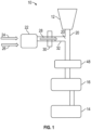
- FIG. 1 illustrated is a schematic of a fluid system, in this embodiment a waste processing system 10 of an extraplanetary habitat, such as a space station, extraplanetary base, or other microgravity environment.
- the waste processing system 10 processes waste and includes components to reclaim water from urine.
- Urine is collected at a toilet 12 and is conveyed to a urine processing assembly (UPA) 14, which in some embodiments utilizes a vacuum distillation process that removes most of the organics and solids from the urine.
- the UPA 14 operates in batches, so prior to being processed by the UPA 14, the urine is stored at a storage tank 16. Because of this storage and batch processing, the urine must be stabilized upon each use of the toilet to inhibit molecular breakdown, organic growth, and/or solids precipitation.
- UPA urine processing assembly
- this additive referred to as urine pretreat
- this additive is input into the urine stream in the waste processing system 10 at, for example, an additive inlet 20.
- a dose pump 22 mixes a concentration of the urine pretreat, shown as 24, with a volume of water 26 to dilute the urine pretreat 24 into a pretreat mixture 28 before adding it to the urine stream at the additive inlet 20.
- a pretreat quality sensor 30 is located in a mixture pathway 32 between the dose pump 22 and the additive inlet 20 to measure the desired properties of the pretreat mixture 28, such as concentration of the urine pretreat 24 in the pretreat mixture 28 as well as the homogeneity, or mix quality, of the pretreat mixture 28. The measured values may be compared to target values to evaluate the performance of the UPA 14. To perform these measurements, the pretreat quality sensor 30 is an optical pretreat quality sensor 30.
- the senor 30 is utilized to measure concentration of the urine pretreat 24 in the pretreat mixture 28, one skilled in the art will readily appreciate that the sensor 30 may be utilized to monitor two-phase flow, for example, gas or solids in a liquid stream.
- the waste processing system 10 may include a phase separator 48 to separate gas and liquid fluids before entering the storage tank 16,
- the phase separator 48 is located downstream of the additive inlet 20.
- the additive inlet 20 is located upstream of the storage tank 16 along the mixture pathway 32, while in other embodiments the additive inlet 20 may deposit the pretreat mixture 28 directly into the storage tank 16 for mixing with the urine therein.
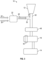
- the optical pretreat quality sensor 30 includes a light source 34, such as an LED light source 34, that emits a light signal 36 through the pretreat mixture 28 and toward a light receiving device, such as a photodiode 38.
- the light signal 36 is received at the photodiode 38 and evaluated by a controller 40, where the measured properties, based on the received light signal 36, are compared to a selected value or range of values. If the properties are outside of the selected range, the controller 40 may initiate an audial and/or visual alarm 42 to alert the users of the condition.
- the light source 34 is an LED light source, but one skilled in the art will readily appreciate that other light sources may be used.
- the light source 34 may be a variable frequency, wavelength, or intensity light source 34, so that the light signal 36 may be varied based on the fluid properties to be evaluated and/or the type of fluid to be evaluated.
- the light signal 36 emitted by the light source 34 is passed through a filter 44 to change, for example, or isolate a wavelength of the light signal 36.
- the optical pretreat quality sensor 30 does not come in contact with the pretreat mixture 28 in the mixture pathway 32. Instead, optical windows 46 are located in the mixture pathway 32, through which the light signal 36 is transmitted across the mixture pathway 32 and through the pretreat mixture 28.
- the fluid pathway 32 is a glass or optically clear tube.
- the optical windows 46 may be eliminated. Eliminating the optical windows 46 reduces the number of corners or crevices along the fluid pathway 32 in which gas may get trapped, thus increasing an accuracy and reliability of the data received from the optical pretreat quality sensor 30.
- the optical pretreat quality sensor 30 may or may not be mechanically connected to the fluid pathway 32. In some embodiments, the optical pretreat quality sensor 30 is a hand-held portable device.
- the optical pretreat quality sensor 30 is located upstream of the storage tank, in other embodiments, such as in FIG. 3 , the optical pretreat quality sensor 30 is alternatively or additionally located at the storage tank 16 to monitor the conditions within the storage tank 16.
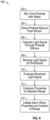
- a method 100 of monitoring flow of a pretreat mixture 28 will now be described.
- urine pretreat 24 is mixed with water 26 at the dose pump 22.
- the resultant pretreat mixture 28 is passed through the mixture pathway 32 past the optical pretreat quality sensor 30.
- the light source 34 transmits the light signal 36 through the mixture pathway 32.
- the light signal 36 is received at the photodiode 38 at step 108, and the light signal 36 is evaluated by the controller 40 to determine one or more properties of the pretreat mixture 28 at step 110.
- the measured properties may be compared to a selected range, and at step 114 the controller 40 may initiate an alarm if the measured properties are outside of the selected range.
- the optical pretreat quality sensor 30 keeps the sensing elements out of contact with the pretreat mixture 28, thus reducing contamination or corrosion of the sensing elements, thereby extending their service life. This further ensures continued accuracy of the measurements of the properties of the pretreat mixture 28.
- the fluid being evaluated is a pretreat mixture 28
- the sensor 30 arrangement disclosed herein may be utilized to evaluate properties of other fluids and mixtures, such as water quality, urine, fuel, coolant, 2 phase flow, liquid & gas for example, or the like.
- the optical sensor 30 may be utilized to measure characteristics or composition of the urine as a monitor of crew members' health, or to measure characteristics of fluids such as a potable water supply aboard, for example, an extraplanetary vehicle or at an extraplanetary habitat. Further, the optical sensor 30 may be utilized to determine ratios and/or phases of fluids in other systems, such as environmental control and life support systems of an extraplanetary vehicle or habitat.
Landscapes
- Physics & Mathematics (AREA)
- Health & Medical Sciences (AREA)
- Life Sciences & Earth Sciences (AREA)
- Engineering & Computer Science (AREA)
- Chemical & Material Sciences (AREA)
- General Health & Medical Sciences (AREA)
- Spectroscopy & Molecular Physics (AREA)
- Analytical Chemistry (AREA)
- General Physics & Mathematics (AREA)
- Biochemistry (AREA)
- Pathology (AREA)
- Immunology (AREA)
- Biomedical Technology (AREA)
- Urology & Nephrology (AREA)
- Environmental & Geological Engineering (AREA)
- Molecular Biology (AREA)
- Biophysics (AREA)
- Food Science & Technology (AREA)
- Mathematical Physics (AREA)
- Theoretical Computer Science (AREA)
- Hematology (AREA)
- Medicinal Chemistry (AREA)
- Toxicology (AREA)
- Environmental Sciences (AREA)
- Biodiversity & Conservation Biology (AREA)
- Remote Sensing (AREA)
- Aviation & Aerospace Engineering (AREA)
- Hydrology & Water Resources (AREA)
- Water Supply & Treatment (AREA)
- Organic Chemistry (AREA)
- Investigating Or Analysing Biological Materials (AREA)
- Investigating Or Analysing Materials By Optical Means (AREA)
Abstract
Description
- Exemplary embodiments pertain to the art of fluid systems, and in particular to measurement of properties of the fluid in the system.
- In fluid systems, such as waste treatment systems, it is desired to measure properties of the fluid, such as concentrations of additives in the fluid or mix quality or homogeneity of the mixture of the fluid. Typically, such determinations are made by using one or more conductivity sensors. Conductivity sensors, however, are electrode-based conductivity sensors that require that critical sensing elements are immersed in corrosive or potentially incompatible fluids, which decreases reliability of the sensors and shortens their useful service life. Alternatively, inductive fluid sensors require high ion levels in the fluid to sense due to the non-contact nature of inductance and the need to generate (induce) a magnetic field.
- In one embodiment, a waste processing system includes a storage tank to collect urine, a dose pump to mix a volume of urine pretreat with a volume of water and dispense the resultant pretreat mixture into the storage tank, and a sensor configured to monitor one or more properties of the pretreat mixture. The sensor is an optical sensor transmitting a light signal through the pretreat mixture.
- Additionally or alternatively, in this or other embodiments a light source of the optical sensor is a light emitting diode (LED).
- Additionally or alternatively, in this or other embodiments the one or more of the wavelength, frequency, or intensity of the light signal can be varied.
- Additionally or alternatively, in this or other embodiments the light signal is transmitted through opposing optical windows in a fluid pathway through which the pretreat mixture is flowed.
- Additionally or alternatively, in this or other embodiments the light signal is received at a photodiode after passing through the pretreat mixture.
- Additionally or alternatively, in this or other embodiments an optical filter is located between the light source and the pretreat mixture.
- Additionally or alternatively, in this or other embodiments the one or more properties include a concentration of urine pretreat in the pretreat mixture and a mixture quality of the pretreat mixture.
- Additionally or alternatively, in this or other embodiments a controller compares the one or more properties to a preselected range.
- In another embodiment, a method of monitoring a flow of a pretreat mixture of a waste processing system includes mixing a volume of urine pretreat with a volume of water at a dose pump defining a pretreat mixture, directing the pretreat mixture along a fluid pathway toward a storage tank, and measuring one or more properties of the pretreat mixture via an optical sensor disposed along the fluid pathway.
- Additionally or alternatively, in this or other embodiments the optical sensor transmits a light signal through the fluid pathway via a light source, and receives the light signal at a photodiode after passing through the pretreat mixture.
- Additionally or alternatively, in this or other embodiments the light source is an LED light source.
- Additionally or alternatively, in this or other embodiments one or more of a wavelength, frequency, or intensity of the light signal is varied.
- Additionally or alternatively, in this or other embodiments the light signal is transmitted through opposing optical windows in the fluid pathway.
- Additionally or alternatively, in this or other embodiments the light signal is transmitted through a filter located between the light source and the fluid pathway.
- Additionally or alternatively, in this or other embodiments the one or more properties is compared to a preselected range.
- Additionally or alternatively, in this or other embodiments an alarm is initiated when the one or more properties are outside of the preselected range.
- Additionally or alternatively, in this or other embodiments the one or more properties include a concentration of urine pretreat in the pretreat mixture and a mixture quality of the pretreat mixture.
- In yet another embodiment, a fluid monitoring system includes a fluid pathway through which a flow of fluid is directed, and an optical sensor configured to transmit a light signal through the flow of fluid to measure one or more properties of the fluid.
- Additionally or alternatively, in this or other embodiments the light signal is transmitted through opposing optical windows in the fluid pathway.
- Additionally or alternatively, in this or other embodiments the light signal is received at a photodiode after passing through the fluid pathway.
- The following descriptions should not be considered limiting in any way. With reference to the accompanying drawings, like elements are numbered alike:
-
FIG. 1 is a partial schematic illustration of an embodiment of a waste processing system; -
FIG. 2 is a schematic illustration of an embodiment of an optical pretreat quality sensor; and -
FIG. 3 is a schematic illustration of another embodiment of a waste processing system; -
FIG. 4 is an illustration of an embodiment of a method of monitoring apretreat mixture 28. - A detailed description of one or more embodiments of the disclosed apparatus and method are presented herein by way of exemplification and not limitation with reference to the Figures.
- Referring now to
FIG. 1 , illustrated is a schematic of a fluid system, in this embodiment awaste processing system 10 of an extraplanetary habitat, such as a space station, extraplanetary base, or other microgravity environment. Thewaste processing system 10 processes waste and includes components to reclaim water from urine. Urine is collected at atoilet 12 and is conveyed to a urine processing assembly (UPA) 14, which in some embodiments utilizes a vacuum distillation process that removes most of the organics and solids from the urine. The UPA 14 operates in batches, so prior to being processed by the UPA 14, the urine is stored at astorage tank 16. Because of this storage and batch processing, the urine must be stabilized upon each use of the toilet to inhibit molecular breakdown, organic growth, and/or solids precipitation. To stabilize the urine, it is mixed with a phosphoric acid with chromate during each use of thetoilet 12. In some embodiments, this additive, referred to as urine pretreat, is input into the urine stream in thewaste processing system 10 at, for example, anadditive inlet 20. In some embodiments, adose pump 22 mixes a concentration of the urine pretreat, shown as 24, with a volume ofwater 26 to dilute the urine pretreat 24 into apretreat mixture 28 before adding it to the urine stream at theadditive inlet 20. - It is desired to know the ratio of urine pretreat 24 to
water 26 in thepretreat mixture 28 exiting thedose pump 22 to ensure proper functioning of thedose pump 22 and thus proper stabilization of the urine. Apretreat quality sensor 30 is located in amixture pathway 32 between thedose pump 22 and theadditive inlet 20 to measure the desired properties of thepretreat mixture 28, such as concentration of the urine pretreat 24 in thepretreat mixture 28 as well as the homogeneity, or mix quality, of thepretreat mixture 28. The measured values may be compared to target values to evaluate the performance of the UPA 14. To perform these measurements, thepretreat quality sensor 30 is an opticalpretreat quality sensor 30. While in the illustrated embodiments, thesensor 30 is utilized to measure concentration of the urine pretreat 24 in thepretreat mixture 28, one skilled in the art will readily appreciate that thesensor 30 may be utilized to monitor two-phase flow, for example, gas or solids in a liquid stream. Further, in some embodiments thewaste processing system 10 may include aphase separator 48 to separate gas and liquid fluids before entering thestorage tank 16, In some embodiments, thephase separator 48 is located downstream of theadditive inlet 20. Further, as shown in the illustrated embodiment, theadditive inlet 20 is located upstream of thestorage tank 16 along themixture pathway 32, while in other embodiments theadditive inlet 20 may deposit thepretreat mixture 28 directly into thestorage tank 16 for mixing with the urine therein. - Referring now to
FIG. 2 , The opticalpretreat quality sensor 30 includes alight source 34, such as anLED light source 34, that emits alight signal 36 through thepretreat mixture 28 and toward a light receiving device, such as aphotodiode 38. Thelight signal 36 is received at thephotodiode 38 and evaluated by acontroller 40, where the measured properties, based on the receivedlight signal 36, are compared to a selected value or range of values. If the properties are outside of the selected range, thecontroller 40 may initiate an audial and/orvisual alarm 42 to alert the users of the condition. - As stated above, in some embodiments the
light source 34 is an LED light source, but one skilled in the art will readily appreciate that other light sources may be used. Thelight source 34 may be a variable frequency, wavelength, orintensity light source 34, so that thelight signal 36 may be varied based on the fluid properties to be evaluated and/or the type of fluid to be evaluated. In some embodiments, thelight signal 36 emitted by thelight source 34 is passed through afilter 44 to change, for example, or isolate a wavelength of thelight signal 36. The opticalpretreat quality sensor 30 does not come in contact with thepretreat mixture 28 in themixture pathway 32. Instead,optical windows 46 are located in themixture pathway 32, through which thelight signal 36 is transmitted across themixture pathway 32 and through thepretreat mixture 28. - In some embodiments, the
fluid pathway 32 is a glass or optically clear tube. In such embodiments, theoptical windows 46 may be eliminated. Eliminating theoptical windows 46 reduces the number of corners or crevices along thefluid pathway 32 in which gas may get trapped, thus increasing an accuracy and reliability of the data received from the opticalpretreat quality sensor 30. The opticalpretreat quality sensor 30 may or may not be mechanically connected to thefluid pathway 32. In some embodiments, the opticalpretreat quality sensor 30 is a hand-held portable device. - While in the embodiment of
FIG. 1 , the opticalpretreat quality sensor 30 is located upstream of the storage tank, in other embodiments, such as inFIG. 3 , the opticalpretreat quality sensor 30 is alternatively or additionally located at thestorage tank 16 to monitor the conditions within thestorage tank 16. - Referring now to
FIG. 4 , amethod 100 of monitoring flow of apretreat mixture 28 will now be described. Atstep 102, urine pretreat 24 is mixed withwater 26 at thedose pump 22. Atstep 104, theresultant pretreat mixture 28 is passed through themixture pathway 32 past the opticalpretreat quality sensor 30. Atstep 106 thelight source 34 transmits thelight signal 36 through themixture pathway 32. Thelight signal 36 is received at thephotodiode 38 atstep 108, and thelight signal 36 is evaluated by thecontroller 40 to determine one or more properties of thepretreat mixture 28 atstep 110. Atstep 112, the measured properties may be compared to a selected range, and atstep 114 thecontroller 40 may initiate an alarm if the measured properties are outside of the selected range. - Use of the optical
pretreat quality sensor 30 keeps the sensing elements out of contact with thepretreat mixture 28, thus reducing contamination or corrosion of the sensing elements, thereby extending their service life. This further ensures continued accuracy of the measurements of the properties of thepretreat mixture 28. While in the present disclosure the fluid being evaluated is apretreat mixture 28, one skilled in the art will readily appreciate that thesensor 30 arrangement disclosed herein may be utilized to evaluate properties of other fluids and mixtures, such as water quality, urine, fuel, coolant, 2 phase flow, liquid & gas for example, or the like. Additionally, theoptical sensor 30 may be utilized to measure characteristics or composition of the urine as a monitor of crew members' health, or to measure characteristics of fluids such as a potable water supply aboard, for example, an extraplanetary vehicle or at an extraplanetary habitat. Further, theoptical sensor 30 may be utilized to determine ratios and/or phases of fluids in other systems, such as environmental control and life support systems of an extraplanetary vehicle or habitat. - The term "about" is intended to include the degree of error associated with measurement of the particular quantity based upon the equipment available at the time of filing the application.
- The terminology used herein is for the purpose of describing particular embodiments only and is not intended to be limiting of the present disclosure. As used herein, the singular forms "a", "an" and "the" are intended to include the plural forms as well, unless the context clearly indicates otherwise. It will be further understood that the terms "comprises" and/or "comprising," when used in this specification, specify the presence of stated features, integers, steps, operations, elements, and/or components, but do not preclude the presence or addition of one or more other features, integers, steps, operations, element components, and/or groups thereof.
- While the present disclosure has been described with reference to an exemplary embodiment or embodiments, it will be understood by those skilled in the art that various changes may be made and equivalents may be substituted for elements thereof without departing from the scope of the present disclosure. In addition, many modifications may be made to adapt a particular situation or material to the teachings of the present disclosure without departing from the essential scope thereof. Therefore, it is intended that the present disclosure not be limited to the particular embodiment disclosed as the best mode contemplated for carrying out this present disclosure, but that the present disclosure will include all embodiments falling within the scope of the claims.
Claims (15)
- A waste processing system, comprising:a storage tank (16) to collect urine;a dose pump (22) to mix a volume of urine pretreat with a volume of water and dispense the resultant pretreat mixture into the storage tank (16); anda sensor (30) configured to monitor one or more properties of the pretreat mixture;wherein the sensor (30) is an optical sensor transmitting a light signal through the pretreat mixture.
- The waste processing system of claim 1, wherein a light source (34) of the optical sensor (30) is a light emitting diode (LED).
- The waste processing system of claim 1 or 2, wherein the one or more of the wavelength, frequency, or intensity of the light signal can be varied.
- The waste processing system of any preceding claim, wherein the light signal is transmitted through opposing optical windows (46) in a fluid pathway through which the pretreat mixture is flowed.
- The waste processing system of any preceding claim, wherein the light signal is received at a photodiode (38) after passing through the pretreat mixture.
- The waste processing system of any preceding claim, further comprising an optical filter disposed between the light source and the pretreat mixture.
- The waste processing system of any preceding claim, wherein the one or more properties include a concentration of urine pretreat in the pretreat mixture and a mixture quality of the pretreat mixture.
- The waste processing system of any preceding claim, further comprising a controller (40) to compare the one or more properties to a preselected range.
- A method of monitoring a flow of a pretreat mixture of a waste processing system, comprising:mixing a volume of urine pretreat with a volume of water at a dose pump defining a pretreat mixture;directing the pretreat mixture along a fluid pathway toward a storage tank;measuring one or more properties of the pretreat mixture via an optical sensor disposed along the fluid pathway.
- The method of claim 9, wherein the optical sensor:transmits a light signal through the fluid pathway via a light source, andreceives the light signal at a photodiode after passing through the pretreat mixture.
- The method of claim 10, wherein the light source is an LED light source; and/or further comprising varying one or more of a wavelength, frequency, or intensity of the light signal; and/or further comprising transmitting the light signal through opposing optical windows in the fluid pathway; and/or further comprising transmitting the light signal through a filter disposed between the light source and the fluid pathway.
- The method of any of claims 9-11, further comprising comparing the one or more properties to a preselected range, and preferably further comprising initiating an alarm when the one or more properties are outside of the preselected range.
- The method of any of claims 9-12, wherein the one or more properties include a concentration of urine pretreat in the pretreat mixture and a mixture quality of the pretreat mixture.
- A fluid monitoring system, comprising:a fluid pathway through which a flow of fluid is directed; andan optical sensor (30) configured to transmit a light signal through the flow of fluid to measure one or more properties of the fluid.
- The system of claim 14, wherein the light signal is transmitted through opposing optical windows (46) in the fluid pathway; and/or
wherein the light signal is received at a photodiode (38) after passing through the fluid pathway.
Applications Claiming Priority (1)
| Application Number | Priority Date | Filing Date | Title |
|---|---|---|---|
| US18/297,091 US20240337595A1 (en) | 2023-04-07 | 2023-04-07 | Optical sensor |
Publications (2)
| Publication Number | Publication Date |
|---|---|
| EP4443140A1 true EP4443140A1 (en) | 2024-10-09 |
| EP4443140B1 EP4443140B1 (en) | 2026-03-18 |
Family
ID=90571795
Family Applications (1)
| Application Number | Title | Priority Date | Filing Date |
|---|---|---|---|
| EP24167723.6A Active EP4443140B1 (en) | 2023-04-07 | 2024-03-28 | Optical sensor |
Country Status (2)
| Country | Link |
|---|---|
| US (1) | US20240337595A1 (en) |
| EP (1) | EP4443140B1 (en) |
Citations (3)
| Publication number | Priority date | Publication date | Assignee | Title |
|---|---|---|---|---|
| US20160054281A1 (en) * | 2014-08-21 | 2016-02-25 | Sharp Kabushiki Kaisha | Optical sensor for fluid analysis |
| WO2018071539A1 (en) * | 2016-10-12 | 2018-04-19 | Knappco Corporation | Optical fluid sensors for cross contamination control systems |
| US10859070B2 (en) * | 2015-01-16 | 2020-12-08 | Hamilton Sundstrand Corporation | Dosing pump |
Family Cites Families (2)
| Publication number | Priority date | Publication date | Assignee | Title |
|---|---|---|---|---|
| AU2018269707B2 (en) * | 2017-05-17 | 2022-12-15 | Spogen Biotech Inc. | Devices, systems, and methods for agrochemical detection and agrochemical compositions |
| EP3884971B1 (en) * | 2020-03-25 | 2024-11-06 | Fenwal, Inc. | Dynamic adjustment of components of a detection assembly |
-
2023
- 2023-04-07 US US18/297,091 patent/US20240337595A1/en not_active Abandoned
-
2024
- 2024-03-28 EP EP24167723.6A patent/EP4443140B1/en active Active
Patent Citations (3)
| Publication number | Priority date | Publication date | Assignee | Title |
|---|---|---|---|---|
| US20160054281A1 (en) * | 2014-08-21 | 2016-02-25 | Sharp Kabushiki Kaisha | Optical sensor for fluid analysis |
| US10859070B2 (en) * | 2015-01-16 | 2020-12-08 | Hamilton Sundstrand Corporation | Dosing pump |
| WO2018071539A1 (en) * | 2016-10-12 | 2018-04-19 | Knappco Corporation | Optical fluid sensors for cross contamination control systems |
Also Published As
| Publication number | Publication date |
|---|---|
| EP4443140B1 (en) | 2026-03-18 |
| US20240337595A1 (en) | 2024-10-10 |
Similar Documents
| Publication | Publication Date | Title |
|---|---|---|
| US6292756B1 (en) | Narrow band infrared water fraction apparatus for gas well and liquid hydrocarbon flow stream use | |
| TWI585389B (en) | System and method for determining liquid phase turbidity of multiphase wastewater | |
| US5192509A (en) | Apparatus for automatic titration | |
| CN102735854B (en) | Analytical device for automated determination of a measured variable of a liquid sample, and method for monitoring measured variable of monitored liquid | |
| EP4031862B1 (en) | Method and apparatus to measure water content of petroleum fluids | |
| CN105716680B (en) | Device for determining a value representing a quantity of liquid and use thereof | |
| US20110155912A1 (en) | Carbon measurement in aqueous samples using oxidation at elevated temperatures and pressures | |
| CN108027272B (en) | Method for testing the functionality of a radar-based fill level measuring device | |
| CN112305238B (en) | Method for measuring liquid volume using a peristaltic pump | |
| AU2001249215A1 (en) | Narrow band infrared water fraction apparatus for gas well and liquid hydrocarbon flow stream use | |
| CN105738287B (en) | Water Test Kits | |
| US20160265953A1 (en) | In-Line Measuring Device | |
| US5160439A (en) | System for controlling coagulant treatment based on monitoring of plural parameters | |
| CN104345034A (en) | Method for determining chemical oxygen demand of liquid sample and analyzer | |
| CN113711033A (en) | Ultra low range chlorine measurement | |
| EP4443140B1 (en) | Optical sensor | |
| US11650302B2 (en) | Method for detecting potential faulty states on an FMCW-based filling level measuring apparatus | |
| CN113711015A (en) | Ultra low range sulfite measurement | |
| US5246590A (en) | Water treatment to reduce fog levels controlled with streaming current detector | |
| US10345321B2 (en) | Automatic analyzer and method | |
| US20150233838A1 (en) | Colorimetric analyzer with de-bubbling | |
| JP2009204431A (en) | Measuring method of chemical oxygen demand | |
| US3694162A (en) | Apparatus for absorbing gases in liquids | |
| SU789079A1 (en) | Device for evaluating water toxicity by fish reaction | |
| JPH10282083A (en) | Method for measuring ammonium ion in water |
Legal Events
| Date | Code | Title | Description |
|---|---|---|---|
| PUAI | Public reference made under article 153(3) epc to a published international application that has entered the european phase |
Free format text: ORIGINAL CODE: 0009012 |
|
| STAA | Information on the status of an ep patent application or granted ep patent |
Free format text: STATUS: THE APPLICATION HAS BEEN PUBLISHED |
|
| AK | Designated contracting states |
Kind code of ref document: A1 Designated state(s): AL AT BE BG CH CY CZ DE DK EE ES FI FR GB GR HR HU IE IS IT LI LT LU LV MC ME MK MT NL NO PL PT RO RS SE SI SK SM TR |
|
| STAA | Information on the status of an ep patent application or granted ep patent |
Free format text: STATUS: REQUEST FOR EXAMINATION WAS MADE |
|
| 17P | Request for examination filed |
Effective date: 20250407 |
|
| GRAP | Despatch of communication of intention to grant a patent |
Free format text: ORIGINAL CODE: EPIDOSNIGR1 |
|
| STAA | Information on the status of an ep patent application or granted ep patent |
Free format text: STATUS: GRANT OF PATENT IS INTENDED |
|
| INTG | Intention to grant announced |
Effective date: 20251009 |
|
| GRAS | Grant fee paid |
Free format text: ORIGINAL CODE: EPIDOSNIGR3 |
|
| GRAA | (expected) grant |
Free format text: ORIGINAL CODE: 0009210 |
|
| STAA | Information on the status of an ep patent application or granted ep patent |
Free format text: STATUS: THE PATENT HAS BEEN GRANTED |
|
| AK | Designated contracting states |
Kind code of ref document: B1 Designated state(s): AL AT BE BG CH CY CZ DE DK EE ES FI FR GB GR HR HU IE IS IT LI LT LU LV MC ME MK MT NL NO PL PT RO RS SE SI SK SM TR |
|
| RAP3 | Party data changed (applicant data changed or rights of an application transferred) |
Owner name: HAMILTON SUNDSTRAND SPACE SYSTEMSINTERNATIONAL, INC. |
|
| REG | Reference to a national code |
Ref country code: CH Ref legal event code: F10 Free format text: ST27 STATUS EVENT CODE: U-0-0-F10-F00 (AS PROVIDED BY THE NATIONAL OFFICE) Effective date: 20260318 Ref country code: GB Ref legal event code: FG4D |
|
| REG | Reference to a national code |
Ref country code: DE Ref legal event code: R096 Ref document number: 602024003196 Country of ref document: DE |
|
| REG | Reference to a national code |
Ref country code: IE Ref legal event code: FG4D |
|
| PGFP | Annual fee paid to national office [announced via postgrant information from national office to epo] |
Ref country code: AT Payment date: 20260414 Year of fee payment: 3 |
|
| PG25 | Lapsed in a contracting state [announced via postgrant information from national office to epo] |
Ref country code: RS Free format text: LAPSE BECAUSE OF FAILURE TO SUBMIT A TRANSLATION OF THE DESCRIPTION OR TO PAY THE FEE WITHIN THE PRESCRIBED TIME-LIMIT Effective date: 20260618 |
|
| PG25 | Lapsed in a contracting state [announced via postgrant information from national office to epo] |
Ref country code: GR Free format text: LAPSE BECAUSE OF FAILURE TO SUBMIT A TRANSLATION OF THE DESCRIPTION OR TO PAY THE FEE WITHIN THE PRESCRIBED TIME-LIMIT Effective date: 20260619 |
|
| REG | Reference to a national code |
Ref country code: LT Ref legal event code: MG9D |
|
| PG25 | Lapsed in a contracting state [announced via postgrant information from national office to epo] |
Ref country code: LT Free format text: LAPSE BECAUSE OF FAILURE TO SUBMIT A TRANSLATION OF THE DESCRIPTION OR TO PAY THE FEE WITHIN THE PRESCRIBED TIME-LIMIT Effective date: 20260318 |
|
| PG25 | Lapsed in a contracting state [announced via postgrant information from national office to epo] |
Ref country code: NO Free format text: LAPSE BECAUSE OF FAILURE TO SUBMIT A TRANSLATION OF THE DESCRIPTION OR TO PAY THE FEE WITHIN THE PRESCRIBED TIME-LIMIT Effective date: 20260618 |
|
| PG25 | Lapsed in a contracting state [announced via postgrant information from national office to epo] |
Ref country code: SE Free format text: LAPSE BECAUSE OF FAILURE TO SUBMIT A TRANSLATION OF THE DESCRIPTION OR TO PAY THE FEE WITHIN THE PRESCRIBED TIME-LIMIT Effective date: 20260318 Ref country code: FI Free format text: LAPSE BECAUSE OF FAILURE TO SUBMIT A TRANSLATION OF THE DESCRIPTION OR TO PAY THE FEE WITHIN THE PRESCRIBED TIME-LIMIT Effective date: 20260318 |
|
| PG25 | Lapsed in a contracting state [announced via postgrant information from national office to epo] |
Ref country code: HR Free format text: LAPSE BECAUSE OF FAILURE TO SUBMIT A TRANSLATION OF THE DESCRIPTION OR TO PAY THE FEE WITHIN THE PRESCRIBED TIME-LIMIT Effective date: 20260318 |
|
| REG | Reference to a national code |
Ref country code: NL Ref legal event code: MP Effective date: 20260318 |
|
| PG25 | Lapsed in a contracting state [announced via postgrant information from national office to epo] |
Ref country code: LV Free format text: LAPSE BECAUSE OF FAILURE TO SUBMIT A TRANSLATION OF THE DESCRIPTION OR TO PAY THE FEE WITHIN THE PRESCRIBED TIME-LIMIT Effective date: 20260318 |
|
| PG25 | Lapsed in a contracting state [announced via postgrant information from national office to epo] |
Ref country code: BG Free format text: LAPSE BECAUSE OF FAILURE TO SUBMIT A TRANSLATION OF THE DESCRIPTION OR TO PAY THE FEE WITHIN THE PRESCRIBED TIME-LIMIT Effective date: 20260318 |