EP4443126A1 - Pressure sensor module and dispensing device having pressure sensor module - Google Patents
Pressure sensor module and dispensing device having pressure sensor module Download PDFInfo
- Publication number
- EP4443126A1 EP4443126A1 EP22900927.9A EP22900927A EP4443126A1 EP 4443126 A1 EP4443126 A1 EP 4443126A1 EP 22900927 A EP22900927 A EP 22900927A EP 4443126 A1 EP4443126 A1 EP 4443126A1
- Authority
- EP
- European Patent Office
- Prior art keywords
- flow channel
- pressure sensor
- sensor module
- moisture prevention
- substrate
- Prior art date
- Legal status (The legal status is an assumption and is not a legal conclusion. Google has not performed a legal analysis and makes no representation as to the accuracy of the status listed.)
- Pending
Links
Images



Classifications
-
- B—PERFORMING OPERATIONS; TRANSPORTING
- B01—PHYSICAL OR CHEMICAL PROCESSES OR APPARATUS IN GENERAL
- B01J—CHEMICAL OR PHYSICAL PROCESSES, e.g. CATALYSIS OR COLLOID CHEMISTRY; THEIR RELEVANT APPARATUS
- B01J4/00—Feed or outlet devices; Feed or outlet control devices
- B01J4/008—Feed or outlet control devices
-
- G—PHYSICS
- G01—MEASURING; TESTING
- G01L—MEASURING FORCE, STRESS, TORQUE, WORK, MECHANICAL POWER, MECHANICAL EFFICIENCY, OR FLUID PRESSURE
- G01L9/00—Measuring steady of quasi-steady pressure of fluid or fluent solid material by electric or magnetic pressure-sensitive elements; Transmitting or indicating the displacement of mechanical pressure-sensitive elements, used to measure the steady or quasi-steady pressure of a fluid or fluent solid material, by electric or magnetic means
- G01L9/0041—Transmitting or indicating the displacement of flexible diaphragms
- G01L9/0051—Transmitting or indicating the displacement of flexible diaphragms using variations in ohmic resistance
-
- G—PHYSICS
- G01—MEASURING; TESTING
- G01L—MEASURING FORCE, STRESS, TORQUE, WORK, MECHANICAL POWER, MECHANICAL EFFICIENCY, OR FLUID PRESSURE
- G01L19/00—Details of, or accessories for, apparatus for measuring steady or quasi-steady pressure of a fluent medium insofar as such details or accessories are not special to particular types of pressure gauges
- G01L19/0007—Fluidic connecting means
- G01L19/0023—Fluidic connecting means for flowthrough systems having a flexible pressure transmitting element
-
- G—PHYSICS
- G01—MEASURING; TESTING
- G01L—MEASURING FORCE, STRESS, TORQUE, WORK, MECHANICAL POWER, MECHANICAL EFFICIENCY, OR FLUID PRESSURE
- G01L19/00—Details of, or accessories for, apparatus for measuring steady or quasi-steady pressure of a fluent medium insofar as such details or accessories are not special to particular types of pressure gauges
- G01L19/0007—Fluidic connecting means
- G01L19/003—Fluidic connecting means using a detachable interface or adapter between the process medium and the pressure gauge
-
- G—PHYSICS
- G01—MEASURING; TESTING
- G01L—MEASURING FORCE, STRESS, TORQUE, WORK, MECHANICAL POWER, MECHANICAL EFFICIENCY, OR FLUID PRESSURE
- G01L19/00—Details of, or accessories for, apparatus for measuring steady or quasi-steady pressure of a fluent medium insofar as such details or accessories are not special to particular types of pressure gauges
- G01L19/0007—Fluidic connecting means
- G01L19/0038—Fluidic connecting means being part of the housing
-
- G—PHYSICS
- G01—MEASURING; TESTING
- G01L—MEASURING FORCE, STRESS, TORQUE, WORK, MECHANICAL POWER, MECHANICAL EFFICIENCY, OR FLUID PRESSURE
- G01L19/00—Details of, or accessories for, apparatus for measuring steady or quasi-steady pressure of a fluent medium insofar as such details or accessories are not special to particular types of pressure gauges
- G01L19/06—Means for preventing overload or deleterious influence of the measured medium on the measuring device or vice versa
- G01L19/0627—Protection against aggressive medium in general
- G01L19/0654—Protection against aggressive medium in general against moisture or humidity
-
- G—PHYSICS
- G01—MEASURING; TESTING
- G01L—MEASURING FORCE, STRESS, TORQUE, WORK, MECHANICAL POWER, MECHANICAL EFFICIENCY, OR FLUID PRESSURE
- G01L19/00—Details of, or accessories for, apparatus for measuring steady or quasi-steady pressure of a fluent medium insofar as such details or accessories are not special to particular types of pressure gauges
- G01L19/14—Housings
- G01L19/147—Details about the mounting of the sensor to support or covering means
-
- G—PHYSICS
- G01—MEASURING; TESTING
- G01L—MEASURING FORCE, STRESS, TORQUE, WORK, MECHANICAL POWER, MECHANICAL EFFICIENCY, OR FLUID PRESSURE
- G01L9/00—Measuring steady of quasi-steady pressure of fluid or fluent solid material by electric or magnetic pressure-sensitive elements; Transmitting or indicating the displacement of mechanical pressure-sensitive elements, used to measure the steady or quasi-steady pressure of a fluid or fluent solid material, by electric or magnetic means
- G01L9/0041—Transmitting or indicating the displacement of flexible diaphragms
- G01L9/0051—Transmitting or indicating the displacement of flexible diaphragms using variations in ohmic resistance
- G01L9/0052—Transmitting or indicating the displacement of flexible diaphragms using variations in ohmic resistance of piezoresistive elements
- G01L9/0054—Transmitting or indicating the displacement of flexible diaphragms using variations in ohmic resistance of piezoresistive elements integral with a semiconducting diaphragm
-
- B—PERFORMING OPERATIONS; TRANSPORTING
- B01—PHYSICAL OR CHEMICAL PROCESSES OR APPARATUS IN GENERAL
- B01J—CHEMICAL OR PHYSICAL PROCESSES, e.g. CATALYSIS OR COLLOID CHEMISTRY; THEIR RELEVANT APPARATUS
- B01J4/00—Feed or outlet devices; Feed or outlet control devices
- B01J4/001—Feed or outlet devices as such, e.g. feeding tubes
- B01J4/002—Nozzle-type elements
-
- B—PERFORMING OPERATIONS; TRANSPORTING
- B01—PHYSICAL OR CHEMICAL PROCESSES OR APPARATUS IN GENERAL
- B01J—CHEMICAL OR PHYSICAL PROCESSES, e.g. CATALYSIS OR COLLOID CHEMISTRY; THEIR RELEVANT APPARATUS
- B01J4/00—Feed or outlet devices; Feed or outlet control devices
- B01J4/02—Feed or outlet devices; Feed or outlet control devices for feeding measured, i.e. prescribed quantities of reagents
Definitions
- the present invention relates to a pressure sensor module and a dispensing device including the pressure sensor module, and particularly to a pressure sensor module using a piezoresistive semiconductor element and a dispensing device including the pressure sensor module.
- the diaphragm is easily deformed when the external pressure is applied.
- PTL 1 discloses a pressure sensor in which a sensor chip is formed by a first semiconductor substrate and a second semiconductor substrate, a strain gauge and a temperature sensor for temperature detection are formed on one surface of the first semiconductor substrate, the sensor chip is accommodated in a package in a state in which these are covered with a corrosion-resistant protective film and the protective film is exposed as a liquid-contacting portion, a rapid temperature change due to a high-temperature fluid to be measured is detected as a thermal shock based on a temperature of the fluid to be measured that is measured by the temperature sensor, and an output is corrected (see an abstract).
- PTL 2 describes a pressure detection device including a pressure sensor having a pressure detection surface that measures a pressure of a fluid, and a flow channel unit in which a flow channel that introduces the fluid into the pressure detection surface is formed, in which the flow channel unit includes a flow channel body in which the flow channel is formed and a ground ring installed in contact with the pressure sensor, and the ground ring is formed of a conductive fluororesin material containing a fluororesin material and a conductive material dispersed in the fluororesin material, and is maintained at a ground potential (see an abstract).
- PTL 1 discloses a pressure sensor in which a silicon material is used for a diaphragm.
- PTL 2 discloses the pressure detection device in which sapphire or ceramics are used for a diaphragm.
- PTL 1 does not disclose that a strength of a joining layer that joins the package to the sensor chip is maintained to ensure reliability of the pressure sensor.
- PTL 2 does not disclose that a strength of a joining layer that joins the flow channel body to the pressure sensor is maintained to ensure reliability of the pressure detection device.
- the invention provides a highly reliable pressure sensor module that maintains a strength of a joining layer that joins a flow channel substrate to a semiconductor element on which a strain detection unit is mounted, and a dispensing device on which the pressure sensor module is mounted.
- a pressure sensor module is a pressure sensor module including: inside a flow channel substrate, a flow channel configured to allow system water to flow therethrough; and a branch channel connected to the flow channel, in which a semiconductor element on which a strain detection unit is mounted is joined to the flow channel substrate via a joining layer at an outlet portion of the branch channel so as to close the outlet portion of the branch channel.
- a moisture prevention film is provided to cover a surface of the flow channel substrate in the branch channel, a surface of the joining layer in the branch channel, and a surface of the semiconductor element on a side where the strain detection unit is not mounted.
- a dispensing device includes the above-described pressure sensor module.
- a highly reliable pressure sensor module that maintains a strength of a joining layer that joins a flow channel substrate to a semiconductor element on which a strain detection unit is mounted, and a dispensing device on which the pressure sensor module is mounted.
- FIG. 1 is an explanatory view showing a basic configuration of the dispensing device 1 according to Embodiment 1.
- the dispensing device 1 includes a nozzle 2 that aspirates or ejects a liquid (fluid to be measured) 22 such as a sample, a syringe pump 4 that adjusts aspiration or ejection of the liquid 22, a pipe 8 that connects the nozzle 2 to the syringe pump 4, a solenoid valve 5, a gear pump 6, and a tank 7 that stores system water 21.
- a liquid fluid to be measured
- the syringe pump 4 includes a container 9 to which the system water 21 is supplied, a plunger 10 that pushes the system water 21 out from the container 9 or draws the system water 21 into the container 9, a ball screw 11 that moves the plunger 10, and a motor 12 that drives the ball screw 11.
- the pipe 8 connects the container 9 to the nozzle 2, and the nozzle 2 aspirates or ejects the liquid 22 using the system water 21 flowing through the pipe 8.
- the dispensing device 1 also includes a control board 14 that controls the solenoid valve 5, the gear pump 6, the motor 12, and two motors 13a installed in a dispensing mechanism 13. That is, the aspiration or ejection of the liquid 22 by the nozzle 2 is controlled by the control board 14.
- the dispensing device 1 further includes a dispensing arm 16 that moves the nozzle 2 to a position where the nozzle 2 aspirates or ejects the liquid 22.
- the nozzle 2 is installed at one end of the dispensing arm 16, and the dispensing mechanism 13 is installed at the other end of the dispensing arm 16.
- the dispensing arm 16 can be rotated and vertically moved by the two motors 13a installed in the dispensing mechanism 13.
- the dispensing arm 16 includes a pressure sensor module 15 therein.
- FIG. 2 is an explanatory view showing the internal state of the pipe 8 in the dispensing arm 16 according to Embodiment 1.
- FIG. 2 shows the internal state of the pipe 8 immediately after aspiration of the liquid 22 or immediately before ejection of the liquid 22.
- the pipe 8 is filled therein with the system water 21 for syringe pressure transmission.
- the liquid 22 can be aspirated or ejected by the nozzle 2 by transmitting a syringe pressure via the system water 21 using the syringe pump 4.
- the liquid 22 When sucking the liquid 22, the liquid 22 is aspirated after dividing air 23 for dividing the liquid 22 from the system water 21 is aspirated by the nozzle 2 such that the liquid 22 is not mixed with the system water 21 inside the pipe 8.
- the nozzle 2 is cleaned.
- the system water 21 is pushed out from the nozzle 2 simultaneously with a flow of cleaning water onto an outer wall of the nozzle 2.
- the system water 21 is pushed out from the nozzle 2 using a pressure of the gear pump 6 with the solenoid valve 5 opened. That is, the solenoid valve 5 and the gear pump 6 are used when cleaning the nozzle 2.
- the system water 21 is pushed out at a higher pressure than when the system water 21 is pushed out by the plunger 10.
- the pressure sensor module 15 installed inside the dispensing arm 16 and installed in communication with the pipe 8 installed inside the dispensing arm 16 detects, with high accuracy, an abnormality such as clogging or empty aspiration of the nozzle 2 that may occur during a dispensing operation.
- the pressure sensor module 15 monitors a pressure change in the system water 21, and detects, with high accuracy, the pressure change in the system water 21, which occurs during the abnormality such as clogging or empty aspiration of the nozzle 2.
- the pressure sensor module 15 in order to sensitively detect, with high accuracy, an abnormality in the nozzle 2, that is, a pressure change in the system water 21 due to the abnormality in the nozzle 2, the pressure sensor module 15 is installed inside the dispensing arm 16 installed at a position closest to the nozzle 2.
- an installation position of the pressure sensor module 15 is not limited to inside the dispensing arm 16.
- the pressure sensor module 15 may be installed in communication with the pipe 8 installed inside the dispensing mechanism 13.
- FIG. 3A is a perspective view showing the pressure sensor module 15 according to Embodiment 1
- FIG. 3B is a cross-sectional view showing the pressure sensor module 15 according to Embodiment 1.
- a long side direction (a direction in which the pipe 8 is formed and a direction in which a flow channel 33 is formed) is a Y direction
- a short side direction is an X direction
- a height direction is a Z direction.
- the pressure sensor module 15 includes a flow channel substrate 25 in which a cylindrical (circular in a cross-sectional shape in a vertical direction) flow channel 33 through which the system water 21 flows is formed.
- the flow channel substrate 25 is preferably made of stainless steel, and may be made of a metal material such as aluminum or titanium or may be made of a resin material such as acrylic as long as the material has high corrosion resistance.
- a flow channel inlet 33a (for example, on a nozzle 2 side) and a flow channel outlet 33b (for example, on a dispensing mechanism 13 side) are formed in the flow channel 33, and a screw portion (not shown) is formed in each of the flow channel inlet 33a and the flow channel outlet 33b.
- the flow channel inlet 33a and the flow channel outlet 33b are connected to the pipe 8 via joints (not shown) connected to the screw portions, respectively.
- a cross-sectional shape of the branch channel 34 in a horizontal direction is preferably circular, and may be elliptical.
- a piezoresistive semiconductor element 3 is installed at a terminal end portion (upper end portion in Embodiment 1) of the branch channel 34 so as to close the branch channel 34.
- the piezoresistive semiconductor element 3 is joined (may be referred to as adhered, mounted, or installed) to the flow channel substrate 25 via a joining layer 32 that joins the piezoresistive semiconductor element 3 to the flow channel substrate 25.
- a strain gauge, a piezoelectric element, or the like may be used instead of the piezoresistive semiconductor element 3.
- the piezoresistive semiconductor element 3 is a thin film semiconductor element having a diaphragm that is deformed by a minute pressure change, formed on the diaphragm, and equipped with a strain detection unit (so-called piezoresistive semiconductor element, and may be referred to as a pressure detection element or pressure sensing unit) that detects the minute pressure change.
- a strain detection unit so-called piezoresistive semiconductor element, and may be referred to as a pressure detection element or pressure sensing unit
- the pressure sensor module 15 includes, inside the flow channel substrate 25, the cylindrical flow channel 33 through which the system water 21 flows and that is formed in the horizontal direction, and the cylindrical branch channel 34 connected to the flow channel 33 (branched from the flow channel 33 in the upper direction that is the vertical direction), and joins the piezoresistive semiconductor element 3 to the flow channel substrate 25 at an outlet portion (terminal end portion) of the branch channel 34 via the joining layer 32 so as to close the outlet portion of the branch channel 34.
- An adhesive material such as a silver paste (adhesive), a silicon-based adhesive, an epoxy-based adhesive, a thermal diffusion bonding agent (adhesive), a thermosetting adhesive, a UV addition adhesive, or a low-melting-point glass (adhesive) is used for the joining layer 32.
- a thickness of the joining layer 32 is preferably 10 um to 70 ⁇ m, particularly preferably 20 um to 40 ⁇ m.
- a moisture prevention film 18 that prevents entry of the system water 21 is formed on an inner surface of the branch channel 34, an inner surface of the joining layer 32, and a back surface of the piezoresistive semiconductor element 3 so as to cover the inner surface of the branch channel 34, the inner surface of the joining layer 32, and the back surface of the piezoresistive semiconductor element 3, that is, so as to isolate the surfaces from the system water 21.
- the inner surface of the branch channel 34 is a surface of the flow channel substrate 25 in the branch channel 34 (surface of the branch channel 34) on a side to be in contact with the system water 21
- the inner surface of the joining layer 32 is a surface of the joining layer 32 in the branch channel 34 on a side to be in contact with the system water 21
- the back surface of the piezoresistive semiconductor element 3 is a surface of the diaphragm (surface of the semiconductor element on a side where the strain detection unit is not mounted) on a side to be in contact with the system water 21.
- the moisture prevention film 18 is formed of a composite film made of an organic film material and an inorganic film material, a single-layer film or multilayer film made of only an organic film material, or a single-layer film or multilayer film made of only an inorganic film material.
- An organic film material such as a moisture prevention coating agent or an inorganic film material such as a metal can be used for the moisture prevention film.
- the moisture prevention film 18 formed on the inner surface of the joining layer 32 is preferably formed thicker than the moisture prevention film 18 formed on the inner surface of the branch channel 34 and the back surface of the piezoresistive semiconductor element 3.
- the moisture prevention film 18 so as to cover the inner surface of the branch channel 34, the inner surface of the joining layer 32, and the back surface of the piezoresistive semiconductor element 3, it is possible to protect the joining layer 32 to be in direct-contact with the system water 21 from the system water 21 (the liquid 22 in some cases) and to prevent water molecules of the system water 21 from entering the inside of the joining layer 32 or a joining interface between the joining layer 32 and the piezoresistive semiconductor element 3 or the flow channel substrate 25.
- the pressure sensor module 15 can be used for a long period of time by forming the moisture prevention film 18 that prevents contact with the system water 21, particularly on the inner surface of the joining layer 32 to be in contact with the system water 21.
- a quadrangular prism shaped space is formed inside the flow channel substrate 25 at a position connected to the flow channel 33 and facing the branch channel 34, which is branched toward an outer surface of the flow channel substrate 25 (Z direction: lower direction in Embodiment 1), and has a rectangular cross-sectional shape in the horizontal direction (rectangle longer in the Y direction than in the X direction, whose width in the X direction is equal to or larger than a width of the branch channel 34 in the X direction).
- the quadrangular prism shaped space may be a cylindrical space (referred to as a "first cylindrical space” for convenience of description). That is, the first cylindrical space is a space formed inside the flow channel substrate 25 at a position connected to the flow channel 33 and facing the branch channel 34, branched toward the outer surface of the flow channel substrate 25 (Z direction: lower direction in Embodiment 1), and having a circular cross-sectional shape in the horizontal direction. A diameter of a horizontal circle of the first cylindrical space is larger than a diameter of a horizontal circle of the branch channel 34.
- a cylindrical space (referred to as a "second cylindrical space” for convenience of description) is formed in communication with the quadrangular prism shaped space or the first cylindrical space in a direction opposite to the branch channel 34 (lower direction in Embodiment 1).
- the second cylindrical space is a space having a circular cross-sectional shape in the horizontal direction, and a diameter of the circle is larger than a Y-direction length of the rectangle of the quadrangular prism or the diameter of the circle of the first cylindrical space.
- the quadrangular prism shaped space or the first cylindrical space corresponds to a portion where the second cylindrical space (which may be referred to as a "cylindrical space" in the description of FIG. 3 and corresponds to a cylindrical space 20 or a cylindrical space 20a in the description from FIG. 4 onwards) communicates with the flow channel 33.
- the second cylindrical space which may be referred to as a "cylindrical space” in the description of FIG. 3 and corresponds to a cylindrical space 20 or a cylindrical space 20a in the description from FIG. 4 onwards
- a cylindrical sealing member 19 is formed in the cylindrical space to seal between the flow channel 33 and the outside of the flow channel substrate 25, that is, to seal the cylindrical space (to close or fill the cylindrical space).
- the sealing member 19 is made of the same material as the flow channel substrate 25.
- a screw portion 36 is formed on an inner surface of the cylindrical space (side surface of the cylindrical space), and the screw portion 36 is also formed around (on an outer surface of) the sealing member 19.
- the sealing member 19 is fitted to the flow channel substrate 25. That is, the screw portion 36 formed around the sealing member 19 is fitted to the screw portion 36 formed on the inner surface of the cylindrical space.
- seal portion 17 that seals between the sealing member 19 and the flow channel substrate 25 is formed around the sealing member 19.
- the seal portion 17 is a seal tape that is formed on the screw portion 36 formed around the sealing member 19 and is made of a polytetrafluoroethylene material. Another seal material or adhesive is used for the seal portion 17.
- a strain detection unit that detects the pressure change is formed (adhered) in the piezoresistive semiconductor element 3, for example, on the diaphragm made of a silicon material, and the diaphragm is deformed by the pressure change in the system water 21 flowing through the flow channel 33.
- the piezoresistive semiconductor element 3 electrically measures a change amount of the diaphragm as the change in the resistance value using, for example, a Wheatstone bridge circuit, converts the change in the resistance value into the change in the pressure value, and measures the pressure of the system water 21 flowing through the flow channel 33.
- a thickness of the diaphragm is preferably 10 um to 50 ⁇ m, particularly preferably 10 um to 30 um.
- a deformation area deformation range
- measurement accuracy of the pressure of the system water 21 can be improved.
- Etching, grinding, or the like can be used for a process of thinning the diaphragm.
- a thin metal film on a surface of the piezoresistive semiconductor element 3 and/or a surface of the flow channel substrate 25. Accordingly, adhesion between the adhesive material used for the joining layer 32 and the piezoresistive semiconductor element 3 or the flow channel substrate 25 can be improved.
- FIG. 4 shows cross-sectional views showing steps (a), (b), and (c) of the manufacturing process for forming the moisture prevention film 18 of the pressure sensor module 15 according to Embodiment 1.
- a left-right direction of the cross-sectional views indicates the Y direction (long side direction), and an upper-lower direction of the cross-sectional views indicates the Z direction (height direction).
- the flow channel substrate 25 is processed.
- the cylindrical flow channel 33 is formed in the flow channel substrate 25 in the Y direction (horizontal direction).
- the cylindrical branch channel 34 is formed in the flow channel substrate 25 in the vertical direction above the flow channel 33 so as to be connected to the flow channel 33 from an upper surface side in the Z direction.
- the cylindrical space (opening) 20 is formed in the flow channel substrate 25 in the vertical direction below the flow channel 33 so as to be connected to the flow channel 33 from a lower surface side in the Z direction. That is, the cylindrical space 20 is formed in a direction opposite to a formation direction of the branch channel 34.
- a diameter X3 of the cylindrical space 20 is formed to be larger than a portion where the cylindrical space 20 communicates with the flow channel 33 (a Y-direction length of a rectangle of a quadrangular prism or a diameter of a circle of a first cylindrical space). That is, a protruding portion 26 protruding to the inside of the cylindrical space 20 is formed in a part of the portion where the cylindrical space 20 communicates with the flow channel 33. In this way, the diameter X3 of the cylindrical space 20 is larger than a width dimension X2 corresponding to the protruding portion 26.
- the portion where the cylindrical space 20 communicates with the flow channel 33, that is, the width dimension X2 corresponding to the protruding portion 26 is formed to be larger than a diameter X1 of the branch channel 34.
- the moisture prevention film 18 when forming the moisture prevention film 18, there is no part that becomes a shadow, and the moisture prevention film 18 can be easily formed.
- the piezoresistive semiconductor element 3 is joined to the flow channel substrate 25 via the joining layer 32 so as to close the branch channel 34.
- the moisture prevention film 18 is formed from a direction of an arrow 35 through the cylindrical space 20.
- the moisture prevention film 18 can be formed so as to cover an inner surface of the branch channel 34, an inner surface of the joining layer 32, and a back surface of the piezoresistive semiconductor element 3.
- the moisture prevention film 18 is formed by spray coating an organic film material such as a moisture prevention coating agent. By spray coating, the moisture prevention film 18 can be uniformly formed.
- a thickness of the moisture prevention film 18 is preferably 10 um to 30 um so as not to inhibit a function of the diaphragm.
- the moisture prevention coating agent tends to remain thick at corner portions due to influence of surface tension. Therefore, by using the moisture prevention coating agent for the moisture prevention film 18, the moisture prevention film 18 formed on the inner surface of the joining layer 32, that is, the moisture prevention film 18 formed on the corner portions (around the joining layer 32) can be formed to be thicker by about 5 um to 10 um than the moisture prevention film 18 formed on the inner surface of the branch channel 34 and the back surface of the piezoresistive semiconductor element 3.
- the cylindrical space 20 is formed in the flow channel substrate 25 from the lower surface side (a surface side opposite to a surface on which the piezoresistive semiconductor element 3 is installed). Then, the moisture prevention film 18 is formed via the cylindrical space 20. Thereafter, the cylindrical space 20 is closed by the sealing member 19. Accordingly, the moisture prevention film 18 can be easily formed.
- FIG. 5 shows cross-sectional views showing steps (a) and (b) of the manufacturing process for forming the moisture prevention film 18 (inorganic film material) of the pressure sensor module 15 according to Embodiment 1.
- a left-right direction of the cross-sectional views indicates the Y direction (long side direction), and an upper-lower direction of the cross-sectional views indicates the Z direction (height direction).
- a moisture prevention film 18b made of an inorganic film material is formed from the direction of the arrow 35 through the cylindrical space 20.
- the inorganic film material is a metal or the like, and is formed using a sputtering device.
- the moisture prevention film 18b When forming the moisture prevention film 18b using the sputtering device, the moisture prevention film 18 having a uniform film thickness can be formed so as to cover an inner surface of the branch channel 34, an inner surface of the joining layer 32, and a back surface of the piezoresistive semiconductor element 3.
- the inorganic film material is preferably the same material as a diaphragm (for example, silicon).
- the diaphragm and the moisture prevention film 18b have the same Young's modulus, and a function of the diaphragm can be maintained. Peeling of the moisture prevention film 18 from the diaphragm due to repeated stress can also be prevented.
- Silicon nitride can also be used as the inorganic film material.
- the film thickness of the moisture prevention film 18b is preferably 200 nm to 800 nm.
- Aluminum having a moisture prevention effect can also be used as the inorganic film material.
- Other materials can be used as long as the material has a moisture prevention effect.
- the moisture prevention film 18b is not limited to be formed by the sputtering device, and any device that can form an inorganic film material may be used, for example, a vapor deposition device, or an electron beam sputtering device.
- the moisture prevention film 18b is also formed on a part of the flow channel 33 around the branch channel 34 and a part of the protruding portion 26, there is no problem in a function of the flow channel substrate 25.
- a mask 38 is formed on a surface of a lower outer surface of the flow channel substrate 25, and the mask 38 is removed after the moisture prevention film 18b is formed. Therefore, the moisture prevention film 18b is not formed on the surface of the lower outer surface of the flow channel substrate 25.
- a cylindrical sealing member 19a (without a screw portion) is installed in the cylindrical space 20a (without a screw portion). Then, a periphery of the sealing member 19a (between the sealing member 19a and the flow channel substrate 25) is sealed using an adhesive 17a. Accordingly, the pressure sensor module 15 is completed.
- a gap between an inner surface of the cylindrical space 20a and the periphery of the sealing member 19a is preferably 100 um to 200 um. Accordingly, the adhesive 17a can be appropriately inserted into the gap, and leakage of the system water 21 can be appropriately prevented.
- a silicon-based adhesive, an epoxy-based adhesive, or the like can be used as the adhesive 17a.
- a stepped portion is formed in a part of a portion where the cylindrical space 20 or the cylindrical space 20a communicates with the flow channel 33.
- FIG. 6A it is preferable to install a sealing member 19b in which the stepped portion is not formed. Accordingly, leakage of the system water 21 can be prevented, and generation of bubbles due to contact of the system water 21 with the stepped portion can be prevented.
- the sealing member 19b has, on the cylindrical sealing member 19, a protrusion 29 that corresponds to (is fitted into) a quadrangular prism shaped space or a first cylindrical space and fills the quadrangular prism shaped space or the first cylindrical space.
- a width in the X direction is a width of the quadrangular prism shaped space in the X direction
- a width in the Y direction is a width of the quadrangular prism shaped space in the X direction (width dimension X2 corresponding to the protruding portion 26)
- a height in the Z direction is a height of the quadrangular prism shaped space in the Z direction.
- a diameter is a diameter of the first cylindrical space
- a height in the Z direction is a height of the first cylindrical space in the Z direction.
- FIG. 6B is a perspective view showing the sealing member 19b of the other pressure sensor module 15 according to Embodiment 1.
- the protrusion 29 of the sealing member 19b has a lower end formed in a planar shape and an upper end formed in a round shape 39.
- the round shape 39 is formed in a concave shape with a curvature equal to that of the cylindrical flow channel 33.
- the protrusion 29 of the sealing member 19b is installed such that the round shape 39 is in the same direction (Y direction) as the flow channel 33. Accordingly, the stepped portion formed in the portion where the cylindrical space 20 or the cylindrical space 20a communicates with the flow channel 33 can be eliminated.
- FIG. 7 is an enlarged cross-sectional view showing the composite film as the moisture prevention film 18 of the pressure sensor module 15 according to Embodiment 1.
- the piezoresistive semiconductor element 3 is joined to the flow channel substrate 25 via the joining layer 32 so as to close the branch channel 34. Then, the moisture prevention film 18 is formed so as to cover the inner surface of the branch channel 34, the inner surface of the joining layer 32, and the back surface of the piezoresistive semiconductor element 3.
- the moisture prevention film 18 can be formed as the composite film or a multilayer film.
- the moisture prevention film 18 that does not allow the system water 21 to pass through is formed.
- a first moisture prevention film 18c is formed so as to cover the inner surface of the joining layer 32 and the joining interface of the joining layer 32
- a second moisture prevention film 18d is formed so as to cover a surface of the first moisture prevention film 18c (surface in contact with the system water 21), the inner surface of the branch channel 34, and the back surface of the piezoresistive semiconductor element 3.
- the first moisture prevention film 18c and the second moisture prevention film 18d are formed of a composite film made of an organic film material and an inorganic film material, a single-layer film or a multilayer film made of only an organic film material, or a single-layer film or a multilayer film made of only an inorganic film material.
- the first moisture prevention film 18c is formed so as to cover the inner surface of the joining layer 32 and the joining interface of the joining layer 32.
- the first moisture prevention film 18c may be formed so as to cover the inner surface of the branch channel 34, the inner surface of the joining layer 32, and the back surface of the piezoresistive semiconductor element 3, and the second moisture prevention film 18d may be formed on the entire surface of the first moisture prevention film 18c.
- the moisture prevention film 18 (the second moisture prevention film 18d, or the first moisture prevention film 18c and the second moisture prevention film 18d) formed so as to cover the back surface of the piezoresistive semiconductor element 3 is preferably formed to be thin (for example, 3 um to 9 ⁇ m) so as not to inhibit the function of the diaphragm. Therefore, a thick polytetrafluoroethylene sheet of about several 100 um cannot be used for the moisture prevention film 18 (the second moisture prevention film 18d, or the first moisture prevention film 18c and the second moisture prevention film 18d).
- FIG. 8 is a perspective view showing the pressure sensor module 15 including the flexible substrate 41 according to Embodiment 1.
- the pressure sensor module 15 has electrical wiring connected to the piezoresistive semiconductor element 3. Electrode pads 42b are formed at a plurality of positions on the piezoresistive semiconductor element 3, and electrode pads 42a are also formed at a plurality of positions on the flexible substrate 41 for the electrical wiring. The electrode pad 42a and the electrode pad 42b are connected by a wire 43.
- a gold wire or an aluminum wire is used as the wire 43.
- An anisotropic conductive film (ACF) or the like may be used to connect the electrode pad 42a and the electrode pad 42b.
- the system water 21 flows through the flow channel 33 and flows into the branch channel 34. Then, a pressure is applied to the piezoresistive semiconductor element 3 due to a pressure change in the system water 21 that flowed into the branch channel 34. The piezoresistive semiconductor element 3 is deformed when the pressure is applied. Then, the flexible substrate 41 detects deformation of the piezoresistive semiconductor element 3 as an electrical signal, and measures the pressure of the system water 21 flowing through the flow channel 33.
- Embodiment 1 it is possible to provide the highly reliable pressure sensor module 15 that maintains a strength of the joining layer 32 that joins the flow channel substrate 25 to the piezoresistive semiconductor element 3.
- the pressure sensor module 15 since the pressure sensor module 15 has a simple structure with a small number of components, the pressure sensor module 15 can be easily downsized, and since the pressure sensor module 15 is small-sized, the pressure sensor module 15 can be installed in the vicinity of the nozzle 2, for example, inside the dispensing arm 16.
- the pressure sensor module 15 can be installed in the vicinity of the nozzle 2, it is possible to provide the highly accurate dispensing device 1 that can measure a minute pressure change in aspiration or ejection of the liquid 22, is highly reliable, estimates a dispensing amount with high accuracy, and detects a dispensing abnormality with high accuracy.
- a distance between the flow channel 33 and the piezoresistive semiconductor element 3 is as short as 3 mm to 5 mm, and the pressure change in the system water 21 flowing through the flow channel 33 can be detected with high accuracy and at high speed.
- FIG. 9 shows cross-sectional views showing steps (a), (b), (c), and (d) of the manufacturing process of the pressure sensor module 15 according to Embodiment 2.
- a left-right direction of the cross-sectional views indicates the Y direction (long side direction), and an upper-lower direction of the cross-sectional views indicates the Z direction (height direction).
- the moisture prevention film 18 is formed from the lower surface side of the flow channel substrate 25 via the cylindrical space 20 formed below the flow channel 33.
- a part of the flow channel substrate 25 is partially formed to form the moisture prevention film 18.
- a donut-shaped (ringshaped) flow channel substrate 25a (first flow channel substrate) is formed as a member above the flow channel 33. That is, the cylindrical flow channel substrate 25a is formed in which the cylindrical branch channel 34 penetrating the flow channel substrate 25a is formed in a center. Then, the screw portion 36 is formed on an outer peripheral portion of the flow channel substrate 25a.
- the piezoresistive semiconductor element 3 is joined to a front surface side of the flow channel substrate 25a via the joining layer 32 so as to close the branch channel 34.
- the moisture prevention film 18 is formed from a back surface side of the flow channel substrate 25a.
- the moisture prevention film 18 is formed by spray coating or sputtering.
- a single-layer film or a composite film made of an organic film or an inorganic film, or a composite film made of an organic film and an inorganic film is used for the moisture prevention film 18.
- the branch channel 34 connected to the flow channel 33 is formed, the semiconductor element on which a strain detection unit is mounted is joined to an outlet portion of the branch channel 34 via the joining layer 32 so as to close the outlet portion of the branch channel 34, and the moisture prevention film 18 is formed so as to cover a surface of the branch channel 34, a surface of the joining layer 32, and a surface of the semiconductor element on a side where the strain detection unit is not mounted.
- a flow channel substrate 25b (second flow channel substrate) is formed.
- the flow channel 33 is formed inside the flow channel substrate 25b, and a cylindrical space (opening) into which the flow channel substrate 25a is fitted is formed above the flow channel 33.
- the screw portion 36 that is fitted to the screw portion 36 formed at an outer peripheral portion of the flow channel substrate 25a is formed at an inner peripheral portion of the cylindrical space.
- a length of the flow channel substrate 25a in the height direction is smaller than a length of the flow channel substrate 25b in the height direction above the flow channel 33.
- the length of the flow channel substrate 25a in the height direction is equal to a length of the cylindrical space in the height direction. Therefore, a cylindrical space connecting the flow channel 33 and the branch channel 34 formed in the flow channel substrate 25a is formed in the flow channel substrate 25b above the flow channel 33.
- a diameter of the cylindrical space is equal to a diameter of the branch channel 34. That is, the protruding portion 26 is formed in the flow channel substrate 25b above the flow channel 33.
- a diameter of the flow channel substrate 25a is equal to a diameter of the cylindrical space 20.
- the flow channel substrate 25a (component) is inserted into a body of the flow channel substrate 25b, and the screw portion 36 is sealed by a seal tape or an adhesive (seal portion 17). Accordingly, the pressure sensor module 15 is completed.
- the flow channel substrate 25a on which the piezoresistive semiconductor element 3 is installed can be handled as a component, and the moisture prevention film 18 can be formed in parallel at a time on a plurality of (a large number of) components, which is excellent in productivity (mass productivity).
- Embodiment 2 it is possible to provide the highly reliable pressure sensor module 15 that maintains a strength of the joining layer 32 that joins the flow channel substrate 25 to the piezoresistive semiconductor element 3.
- FIG. 10 shows cross-sectional views showing steps (a), (b), and (c) of the manufacturing process of the pressure sensor module 15 according to Embodiment 3.
- a left-right direction of the cross-sectional views indicates the Y direction (long side direction), and an upper-lower direction of the cross-sectional views indicates the Z direction (height direction).
- the flow channel 33 is formed in the flow channel substrate 25, the cylindrical branch channel 34 and the cylindrical space 20 are formed after the flow channel 33 is formed, the moisture prevention film 18 is formed from the lower surface side of the flow channel substrate 25 via the cylindrical space 20, and then the sealing member 19 is formed.
- the cylindrical branch channel 34 and the cylindrical space 20 are formed in the flow channel substrate 25 before the flow channel 33 is formed, then the moisture prevention film 18 is formed from a lower surface side of the flow channel substrate 25 via the cylindrical space 20, then the sealing member 19 is formed, and finally the flow channel 33 is formed.
- the cylindrical branch channel 34 and the cylindrical space 20 are formed in the vicinity of a central portion of the flow channel substrate 25c so as to penetrate the flow channel substrate 25c in a vertical direction from a back surface side of the flow channel substrate 25c.
- the cylindrical branch channel 34 and the cylindrical space 20 are formed in two stages (a diameter of the cylindrical branch channel 34 is smaller than a diameter of the cylindrical space 20) so as to have a protruding cross-sectional shape in the vertical direction.
- the screw portion 36 is formed at an inner peripheral portion of the cylindrical space 20.
- the piezoresistive semiconductor element 3 is joined to a front surface side of the flow channel substrate 25c via the joining layer 32 so as to close the branch channel 34.
- a diameter of a first stage (lower stage) of the two-stage cylindrical sealing member 19c is equal to a diameter of a first stage (lower stage) of the cylindrical space 20, and a diameter of a second stage (upper stage) of the two-stage cylindrical sealing member 19c is equal to a diameter of a second stage (upper stage) of the cylindrical space 20.
- a length of the first stage (lower stage) of the two-stage cylindrical sealing member 19c in the height direction is equal to a length of the first stage (lower stage) of the cylindrical space 20 in the height direction, and a length of the second stage (upper stage) of the two-stage cylindrical sealing member 19c in the height direction is smaller than a length of the second stage (upper stage) of the cylindrical space 20 in the height direction.
- the cylindrical flow channel 33 is formed in the Y direction from a side surface side of the flow channel substrate 25.
- the flow channel 33 is formed to be connected to the branch channel 34. Accordingly, the pressure sensor module 15 is completed. In this way, since the flow channel 33 is formed last, the pressure sensor module 15 having the flow channel 33 of various diameters can be manufactured.
- a screw portion (not shown) connected to the pipe 8 is formed at each of the flow channel inlet 33a and the flow channel outlet 33b of the flow channel 33.
- Embodiment 3 it is possible to provide the highly reliable pressure sensor module 15 that maintains a strength of the joining layer 32 that joins the flow channel substrate 25 to the piezoresistive semiconductor element 3.
- FIG. 11 shows cross-sectional views showing steps (a), (b), and (c) of the manufacturing process of the pressure sensor module 15 according to Embodiment 4.
- a left-right direction of the cross-sectional views indicates the Y direction (long side direction), and an upper-lower direction of the cross-sectional views indicates the Z direction (height direction).
- Embodiment 4 has characteristics of Embodiment 2 and Embodiment 3, in which a part of the flow channel substrate 25 is partially formed to form the moisture prevention film 18, the cylindrical branch channel 34 is formed in the flow channel substrate 25 before the flow channel 33 is formed, the moisture prevention film 18 is formed, a part of the partially formed flow channel substrate 25 is inserted into a body of the flow channel substrate 25, and finally the flow channel 33 is formed.
- a flow channel substrate 25e is formed.
- a cylindrical space 20b is formed in the vicinity of a central portion of the flow channel substrate 25e so as not to penetrate the flow channel substrate 25e from a front surface side of the flow channel substrate 25e.
- the screw portion 36 is formed at an inner peripheral portion of the cylindrical space 20b.
- a donut-shaped (ringshaped) flow channel substrate 25d is formed. That is, the cylindrical flow channel substrate 25d (first flow channel substrate) in which the cylindrical branch channel 34 is formed in a center is formed.
- the cylindrical flow channel substrate 25d is formed in which the cylindrical branch channel 34 penetrating the flow channel substrate 25d is formed in a center. Then, the screw portion 36 that is fitted to the screw portion 36 formed at an inner peripheral portion of the cylindrical space 20b is formed at an outer peripheral portion of the flow channel substrate 25d.
- the piezoresistive semiconductor element 3 is joined to a front surface side of the flow channel substrate 25a via the joining layer 32 so as to close the branch channel 34.
- the moisture prevention film 18 is formed from a back surface side of the flow channel substrate 25d.
- the moisture prevention film 18 is formed by spray coating or sputtering.
- a single-layer film or a composite film made of an organic film or an inorganic film, or a composite film made of an organic film and an inorganic film is used for the moisture prevention film 18.
- the flow channel substrate 25d is inserted into the flow channel substrate 25e (second flow channel substrate). That is, the screw portion 36 formed at the outer peripheral portion of the flow channel substrate 25d is fitted to the screw portion 36 formed at the inner peripheral portion of the cylindrical space 20b.
- the screw portion 36 is sealed by a seal tape or an adhesive (seal portion 17).
- the cylindrical flow channel 33 is formed in the Y direction from a side surface side of the flow channel substrate 25.
- the flow channel 33 is formed to be connected to the branch channel 34. Accordingly, the pressure sensor module 15 is completed. In this way, since the flow channel 33 is formed last, the pressure sensor module 15 having the flow channel 33 of various diameters can be manufactured.
- a screw portion (not shown) connected to the pipe 8 is formed at each of the flow channel inlet 33a and the flow channel outlet 33b of the flow channel 33.
- the flow channel substrate 25d on which the piezoresistive semiconductor element 3 is installed can be handled as a component, and the moisture prevention film 18 can be formed in parallel at a time on a plurality of (a large number of) components, which is excellent in productivity (mass productivity).
- a part of a configuration of one embodiment may be replaced with a part of a configuration of another embodiment.
- a configuration of another embodiment may be added to a configuration of one embodiment.
- a part of a configuration of each embodiment may be deleted, added with a part of another configuration, or replaced with a part of another configuration.
Landscapes
- Physics & Mathematics (AREA)
- General Physics & Mathematics (AREA)
- Chemical & Material Sciences (AREA)
- Organic Chemistry (AREA)
- Chemical Kinetics & Catalysis (AREA)
- Analytical Chemistry (AREA)
- Measuring Fluid Pressure (AREA)
Abstract
Description
- The present invention relates to a pressure sensor module and a dispensing device including the pressure sensor module, and particularly to a pressure sensor module using a piezoresistive semiconductor element and a dispensing device including the pressure sensor module.
- In a general pressure sensor, a pressure detection element is formed (adhered) on a diaphragm made of a nonconductive material such as a silicon material or a ceramic material, and the diaphragm is deformed by an external pressure of a liquid or a gas. Then, the pressure sensor electrically measures a change amount of the diaphragm as a change in a resistance value using a Wheatstone bridge circuit or the like, converts the change in the resistance value into a change in a pressure value, and measures an external pressure.
- In particular, the diaphragm formed on a part of a semiconductor substrate is formed by thinning a back surface of the semiconductor substrate on which a pressure detection element is formed by anisotropic-etching or dry-etching silicon.
- By etching a part of the semiconductor substrate, a certain measurement area is ensured, and the back surface of the semiconductor substrate on which the pressure detection element is formed is processed to be thin to any thickness. In this way, by thinning a part of the semiconductor substrate and forming the diaphragm, the diaphragm is easily deformed when the external pressure is applied.
- As the related art in such a technical field, there are, for example,
PTL 1 andPTL 2. -
PTL 1 discloses a pressure sensor in which a sensor chip is formed by a first semiconductor substrate and a second semiconductor substrate, a strain gauge and a temperature sensor for temperature detection are formed on one surface of the first semiconductor substrate, the sensor chip is accommodated in a package in a state in which these are covered with a corrosion-resistant protective film and the protective film is exposed as a liquid-contacting portion, a rapid temperature change due to a high-temperature fluid to be measured is detected as a thermal shock based on a temperature of the fluid to be measured that is measured by the temperature sensor, and an output is corrected (see an abstract). -
PTL 2 describes a pressure detection device including a pressure sensor having a pressure detection surface that measures a pressure of a fluid, and a flow channel unit in which a flow channel that introduces the fluid into the pressure detection surface is formed, in which the flow channel unit includes a flow channel body in which the flow channel is formed and a ground ring installed in contact with the pressure sensor, and the ground ring is formed of a conductive fluororesin material containing a fluororesin material and a conductive material dispersed in the fluororesin material, and is maintained at a ground potential (see an abstract). -
- PTL 1:
JP2018-115944A - PTL 2:
JP2018-072106A -
PTL 1 discloses a pressure sensor in which a silicon material is used for a diaphragm.PTL 2 discloses the pressure detection device in which sapphire or ceramics are used for a diaphragm. - However,
PTL 1 does not disclose that a strength of a joining layer that joins the package to the sensor chip is maintained to ensure reliability of the pressure sensor.PTL 2 does not disclose that a strength of a joining layer that joins the flow channel body to the pressure sensor is maintained to ensure reliability of the pressure detection device. - In view of the above, the invention provides a highly reliable pressure sensor module that maintains a strength of a joining layer that joins a flow channel substrate to a semiconductor element on which a strain detection unit is mounted, and a dispensing device on which the pressure sensor module is mounted.
- In order to solve the above-described problem, a pressure sensor module according to the invention is a pressure sensor module including: inside a flow channel substrate, a flow channel configured to allow system water to flow therethrough; and a branch channel connected to the flow channel, in which a semiconductor element on which a strain detection unit is mounted is joined to the flow channel substrate via a joining layer at an outlet portion of the branch channel so as to close the outlet portion of the branch channel. A moisture prevention film is provided to cover a surface of the flow channel substrate in the branch channel, a surface of the joining layer in the branch channel, and a surface of the semiconductor element on a side where the strain detection unit is not mounted.
- A dispensing device according to the invention includes the above-described pressure sensor module.
- According to the invention, it is possible to provide a highly reliable pressure sensor module that maintains a strength of a joining layer that joins a flow channel substrate to a semiconductor element on which a strain detection unit is mounted, and a dispensing device on which the pressure sensor module is mounted.
- Problems, configurations, and effects other than those described above will be clarified by description of the following embodiments.
-
- [
FIG. 1] FIG. 1 is an explanatory view showing a basic configuration of adispensing device 1 according toEmbodiment 1. - [
FIG. 2] FIG. 2 is an explanatory view showing an internal state of apipe 8 in a dispensingarm 16 according toEmbodiment 1. - [
FIG. 3A] FIG. 3A is a perspective view showing apressure sensor module 15 according toEmbodiment 1. - [
FIG. 3B] FIG. 3B is a cross-sectional view showing thepressure sensor module 15 according toEmbodiment 1. - [
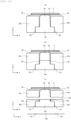
FIG. 4] FIG. 4 shows cross-sectional views showing steps (a), (b), and (c) of a manufacturing process for forming amoisture prevention film 18 of thepressure sensor module 15 according toEmbodiment 1. - [
FIG. 5] FIG. 5 shows cross-sectional views showing steps (a) and (b) of a manufacturing process for forming the moisture prevention film 18 (inorganic film material) of thepressure sensor module 15 according toEmbodiment 1. - [
FIG. 6A] FIG. 6A is a cross-sectional view showing anotherpressure sensor module 15 according toEmbodiment 1. - [
FIG. 6B] FIG. 6B is a perspective view showing a sealingmember 19b of anotherpressure sensor module 15 according toEmbodiment 1. - [
FIG. 7] FIG. 7 is an enlarged cross-sectional view showing a composite film as themoisture prevention film 18 of thepressure sensor module 15 according toEmbodiment 1. - [
FIG. 8] FIG. 8 is a perspective view showing thepressure sensor module 15 including aflexible substrate 41 according toEmbodiment 1. - [
FIG. 9] FIG. 9 shows cross-sectional views showing steps (a), (b), (c), and (d) of a manufacturing process of thepressure sensor module 15 according toEmbodiment 2. - [
FIG. 10] FIG. 10 shows cross-sectional views showing steps (a), (b), and (c) of a manufacturing process of thepressure sensor module 15 according toEmbodiment 3. - [
FIG. 11] FIG. 11 shows cross-sectional views showing steps (a), (b), and (c) of a manufacturing process of thepressure sensor module 15 according toEmbodiment 4. - Hereinafter, embodiments of the invention will be described with reference to the drawings. In the drawings, substantially the same or similar components may be denoted by the same reference numerals. In the drawings, when description of a configuration is redundant, the redundant description may be omitted.
- First, a basic configuration of a
dispensing device 1 according toEmbodiment 1 will be described. -
FIG. 1 is an explanatory view showing a basic configuration of thedispensing device 1 according toEmbodiment 1. - The
dispensing device 1 includes anozzle 2 that aspirates or ejects a liquid (fluid to be measured) 22 such as a sample, asyringe pump 4 that adjusts aspiration or ejection of theliquid 22, apipe 8 that connects thenozzle 2 to thesyringe pump 4, asolenoid valve 5, agear pump 6, and a tank 7 that storessystem water 21. - The
syringe pump 4 includes acontainer 9 to which thesystem water 21 is supplied, aplunger 10 that pushes thesystem water 21 out from thecontainer 9 or draws thesystem water 21 into thecontainer 9, aball screw 11 that moves theplunger 10, and amotor 12 that drives theball screw 11. - The
pipe 8 connects thecontainer 9 to thenozzle 2, and thenozzle 2 aspirates or ejects theliquid 22 using thesystem water 21 flowing through thepipe 8. - The
dispensing device 1 also includes acontrol board 14 that controls thesolenoid valve 5, thegear pump 6, themotor 12, and twomotors 13a installed in adispensing mechanism 13. That is, the aspiration or ejection of theliquid 22 by thenozzle 2 is controlled by thecontrol board 14. - The
dispensing device 1 further includes a dispensingarm 16 that moves thenozzle 2 to a position where thenozzle 2 aspirates or ejects theliquid 22. Thenozzle 2 is installed at one end of the dispensingarm 16, and thedispensing mechanism 13 is installed at the other end of the dispensingarm 16. In order to move thenozzle 2, the dispensingarm 16 can be rotated and vertically moved by the twomotors 13a installed in thedispensing mechanism 13. - The dispensing
arm 16 includes apressure sensor module 15 therein. - Next, an internal state of the
pipe 8 in the dispensingarm 16 according toEmbodiment 1 will be described. -
FIG. 2 is an explanatory view showing the internal state of thepipe 8 in the dispensingarm 16 according toEmbodiment 1.FIG. 2 shows the internal state of thepipe 8 immediately after aspiration of the liquid 22 or immediately before ejection of the liquid 22. - The
pipe 8 is filled therein with thesystem water 21 for syringe pressure transmission. The liquid 22 can be aspirated or ejected by thenozzle 2 by transmitting a syringe pressure via thesystem water 21 using thesyringe pump 4. - When sucking the liquid 22 by the
nozzle 2, theplunger 10 is drawn into thecontainer 9 with thesolenoid valve 5 closed. On the other hand, when ejecting the liquid 22 from thenozzle 2, theplunger 10 is pushed out from thecontainer 9 with thesolenoid valve 5 closed. - When sucking the liquid 22, the liquid 22 is aspirated after dividing
air 23 for dividing the liquid 22 from thesystem water 21 is aspirated by thenozzle 2 such that the liquid 22 is not mixed with thesystem water 21 inside thepipe 8. - After the liquid 22 is ejected from the
nozzle 2, thenozzle 2 is cleaned. When cleaning thenozzle 2, thesystem water 21 is pushed out from thenozzle 2 simultaneously with a flow of cleaning water onto an outer wall of thenozzle 2. When thesystem water 21 is pushed out from thenozzle 2 at the time of cleaning thenozzle 2, thesystem water 21 is pushed out from thenozzle 2 using a pressure of thegear pump 6 with thesolenoid valve 5 opened. That is, thesolenoid valve 5 and thegear pump 6 are used when cleaning thenozzle 2. When cleaning thenozzle 2, thesystem water 21 is pushed out at a higher pressure than when thesystem water 21 is pushed out by theplunger 10. - The
pressure sensor module 15 installed inside the dispensingarm 16 and installed in communication with thepipe 8 installed inside the dispensingarm 16 detects, with high accuracy, an abnormality such as clogging or empty aspiration of thenozzle 2 that may occur during a dispensing operation. Thepressure sensor module 15 monitors a pressure change in thesystem water 21, and detects, with high accuracy, the pressure change in thesystem water 21, which occurs during the abnormality such as clogging or empty aspiration of thenozzle 2. - In
Embodiment 1, in order to sensitively detect, with high accuracy, an abnormality in thenozzle 2, that is, a pressure change in thesystem water 21 due to the abnormality in thenozzle 2, thepressure sensor module 15 is installed inside the dispensingarm 16 installed at a position closest to thenozzle 2. However, an installation position of thepressure sensor module 15 is not limited to inside the dispensingarm 16. For example, thepressure sensor module 15 may be installed in communication with thepipe 8 installed inside thedispensing mechanism 13. - Next, the
pressure sensor module 15 according toEmbodiment 1 will be described. -
FIG. 3A is a perspective view showing thepressure sensor module 15 according toEmbodiment 1, andFIG. 3B is a cross-sectional view showing thepressure sensor module 15 according toEmbodiment 1. - Here, for convenience of description, in the
pressure sensor module 15, a long side direction (a direction in which thepipe 8 is formed and a direction in which aflow channel 33 is formed) is a Y direction, a short side direction is an X direction, and a height direction is a Z direction. - The
pressure sensor module 15 includes aflow channel substrate 25 in which a cylindrical (circular in a cross-sectional shape in a vertical direction)flow channel 33 through which thesystem water 21 flows is formed. Theflow channel substrate 25 is preferably made of stainless steel, and may be made of a metal material such as aluminum or titanium or may be made of a resin material such as acrylic as long as the material has high corrosion resistance. - A
flow channel inlet 33a (for example, on anozzle 2 side) and aflow channel outlet 33b (for example, on adispensing mechanism 13 side) are formed in theflow channel 33, and a screw portion (not shown) is formed in each of theflow channel inlet 33a and theflow channel outlet 33b. Theflow channel inlet 33a and theflow channel outlet 33b are connected to thepipe 8 via joints (not shown) connected to the screw portions, respectively. - A cylindrical (cylindrical shape with a diameter equal to or larger than a diameter of the flow channel 33)
branch channel 34 connected to theflow channel 33 and branched toward an outer surface of the flow channel substrate 25 (Z direction: upper direction in Embodiment 1) is formed inside theflow channel substrate 25. A cross-sectional shape of thebranch channel 34 in a horizontal direction is preferably circular, and may be elliptical. - A
piezoresistive semiconductor element 3 is installed at a terminal end portion (upper end portion in Embodiment 1) of thebranch channel 34 so as to close thebranch channel 34. Thepiezoresistive semiconductor element 3 is joined (may be referred to as adhered, mounted, or installed) to theflow channel substrate 25 via a joininglayer 32 that joins thepiezoresistive semiconductor element 3 to theflow channel substrate 25. A strain gauge, a piezoelectric element, or the like may be used instead of thepiezoresistive semiconductor element 3. - Here, the
piezoresistive semiconductor element 3 is a thin film semiconductor element having a diaphragm that is deformed by a minute pressure change, formed on the diaphragm, and equipped with a strain detection unit (so-called piezoresistive semiconductor element, and may be referred to as a pressure detection element or pressure sensing unit) that detects the minute pressure change. - That is, the
pressure sensor module 15 includes, inside theflow channel substrate 25, thecylindrical flow channel 33 through which thesystem water 21 flows and that is formed in the horizontal direction, and thecylindrical branch channel 34 connected to the flow channel 33 (branched from theflow channel 33 in the upper direction that is the vertical direction), and joins thepiezoresistive semiconductor element 3 to theflow channel substrate 25 at an outlet portion (terminal end portion) of thebranch channel 34 via the joininglayer 32 so as to close the outlet portion of thebranch channel 34. - An adhesive material such as a silver paste (adhesive), a silicon-based adhesive, an epoxy-based adhesive, a thermal diffusion bonding agent (adhesive), a thermosetting adhesive, a UV addition adhesive, or a low-melting-point glass (adhesive) is used for the joining
layer 32. A thickness of the joininglayer 32 is preferably 10 um to 70 µm, particularly preferably 20 um to 40 µm. - In the
pressure sensor module 15, amoisture prevention film 18 that prevents entry of thesystem water 21 is formed on an inner surface of thebranch channel 34, an inner surface of the joininglayer 32, and a back surface of thepiezoresistive semiconductor element 3 so as to cover the inner surface of thebranch channel 34, the inner surface of the joininglayer 32, and the back surface of thepiezoresistive semiconductor element 3, that is, so as to isolate the surfaces from thesystem water 21. - The inner surface of the
branch channel 34 is a surface of theflow channel substrate 25 in the branch channel 34 (surface of the branch channel 34) on a side to be in contact with thesystem water 21, the inner surface of the joininglayer 32 is a surface of the joininglayer 32 in thebranch channel 34 on a side to be in contact with thesystem water 21, and the back surface of thepiezoresistive semiconductor element 3 is a surface of the diaphragm (surface of the semiconductor element on a side where the strain detection unit is not mounted) on a side to be in contact with thesystem water 21. - The
moisture prevention film 18 is formed of a composite film made of an organic film material and an inorganic film material, a single-layer film or multilayer film made of only an organic film material, or a single-layer film or multilayer film made of only an inorganic film material. - An organic film material such as a moisture prevention coating agent or an inorganic film material such as a metal can be used for the moisture prevention film.
- The
moisture prevention film 18 formed on the inner surface of the joininglayer 32 is preferably formed thicker than themoisture prevention film 18 formed on the inner surface of thebranch channel 34 and the back surface of thepiezoresistive semiconductor element 3. - In this way, by forming the
moisture prevention film 18 so as to cover the inner surface of thebranch channel 34, the inner surface of the joininglayer 32, and the back surface of thepiezoresistive semiconductor element 3, it is possible to protect the joininglayer 32 to be in direct-contact with thesystem water 21 from the system water 21 (the liquid 22 in some cases) and to prevent water molecules of thesystem water 21 from entering the inside of the joininglayer 32 or a joining interface between the joininglayer 32 and thepiezoresistive semiconductor element 3 or theflow channel substrate 25. - Accordingly, it is possible to prevent swelling of the joining
layer 32 that joins theflow channel substrate 25 to thepiezoresistive semiconductor element 3, peeling of the joininglayer 32 from theflow channel substrate 25 or thepiezoresistive semiconductor element 3, deterioration of the joininglayer 32, and the like, to maintain a strength of the joininglayer 32, and to improve reliability of thepressure sensor module 15. - Since a pressure change in the
system water 21 is repeatedly measured, when thepressure sensor module 15 is used for a long period of time, the water molecules of thesystem water 21 enter the inside of the joininglayer 32, or the joining interface between the joininglayer 32 and thepiezoresistive semiconductor element 3 or theflow channel substrate 25, which may cause a stress change in the material of the joininglayer 32 or a decrease in a joining strength of the joininglayer 32. - Therefore, the
pressure sensor module 15 can be used for a long period of time by forming themoisture prevention film 18 that prevents contact with thesystem water 21, particularly on the inner surface of the joininglayer 32 to be in contact with thesystem water 21. - A quadrangular prism shaped space is formed inside the
flow channel substrate 25 at a position connected to theflow channel 33 and facing thebranch channel 34, which is branched toward an outer surface of the flow channel substrate 25 (Z direction: lower direction in Embodiment 1), and has a rectangular cross-sectional shape in the horizontal direction (rectangle longer in the Y direction than in the X direction, whose width in the X direction is equal to or larger than a width of thebranch channel 34 in the X direction). - The quadrangular prism shaped space may be a cylindrical space (referred to as a "first cylindrical space" for convenience of description). That is, the first cylindrical space is a space formed inside the
flow channel substrate 25 at a position connected to theflow channel 33 and facing thebranch channel 34, branched toward the outer surface of the flow channel substrate 25 (Z direction: lower direction in Embodiment 1), and having a circular cross-sectional shape in the horizontal direction. A diameter of a horizontal circle of the first cylindrical space is larger than a diameter of a horizontal circle of thebranch channel 34. - Further, inside the
flow channel substrate 25, a cylindrical space (referred to as a "second cylindrical space" for convenience of description) is formed in communication with the quadrangular prism shaped space or the first cylindrical space in a direction opposite to the branch channel 34 (lower direction in Embodiment 1). The second cylindrical space is a space having a circular cross-sectional shape in the horizontal direction, and a diameter of the circle is larger than a Y-direction length of the rectangle of the quadrangular prism or the diameter of the circle of the first cylindrical space. - The quadrangular prism shaped space or the first cylindrical space corresponds to a portion where the second cylindrical space (which may be referred to as a "cylindrical space" in the description of
FIG. 3 and corresponds to acylindrical space 20 or acylindrical space 20a in the description fromFIG. 4 onwards) communicates with theflow channel 33. - A cylindrical sealing
member 19 is formed in the cylindrical space to seal between theflow channel 33 and the outside of theflow channel substrate 25, that is, to seal the cylindrical space (to close or fill the cylindrical space). The sealingmember 19 is made of the same material as theflow channel substrate 25. - A
screw portion 36 is formed on an inner surface of the cylindrical space (side surface of the cylindrical space), and thescrew portion 36 is also formed around (on an outer surface of) the sealingmember 19. The sealingmember 19 is fitted to theflow channel substrate 25. That is, thescrew portion 36 formed around the sealingmember 19 is fitted to thescrew portion 36 formed on the inner surface of the cylindrical space. - A
seal portion 17 that seals between the sealingmember 19 and theflow channel substrate 25 is formed around the sealingmember 19. Here, theseal portion 17 is a seal tape that is formed on thescrew portion 36 formed around the sealingmember 19 and is made of a polytetrafluoroethylene material. Another seal material or adhesive is used for theseal portion 17. - In this way, a gap around the sealing
member 19, that is, between the inner surface of the cylindrical space and a periphery of the sealingmember 19 is sealed by thescrew portions 36 and theseal portion 17. Accordingly, leakage of thesystem water 21 can be prevented. - In the
piezoresistive semiconductor element 3, the diaphragm is bent (strained) and deformed by the pressure change in thesystem water 21 flowing through theflow channel 33. Then, a change in a resistance value due to bending (strain) deformation of the diaphragm is electrically measured, the change in the resistance value is converted into a change in a pressure value, and a pressure of thesystem water 21 flowing through theflow channel 33 is measured. - That is, a strain detection unit that detects the pressure change is formed (adhered) in the
piezoresistive semiconductor element 3, for example, on the diaphragm made of a silicon material, and the diaphragm is deformed by the pressure change in thesystem water 21 flowing through theflow channel 33. Then, thepiezoresistive semiconductor element 3 electrically measures a change amount of the diaphragm as the change in the resistance value using, for example, a Wheatstone bridge circuit, converts the change in the resistance value into the change in the pressure value, and measures the pressure of thesystem water 21 flowing through theflow channel 33. - For example, a thickness of the diaphragm is preferably 10 um to 50 µm, particularly preferably 10 um to 30 um. By reducing the thickness of the diaphragm, a deformation area (deformation range) can be increased with respect to a minute pressure change in the
system water 21, and measurement accuracy of the pressure of thesystem water 21 can be improved. - Etching, grinding, or the like can be used for a process of thinning the diaphragm.
- It is preferable to form a thin film insulator on a surface of the thinned diaphragm. Accordingly, even when the thickness of the diaphragm is reduced by the process of thinning the diaphragm, electrical leakage caused by a structure of the
piezoresistive semiconductor element 3 or electrical conductivity of the diaphragm can be prevented. - It is preferable to form a thin metal film on a surface of the
piezoresistive semiconductor element 3 and/or a surface of theflow channel substrate 25. Accordingly, adhesion between the adhesive material used for the joininglayer 32 and thepiezoresistive semiconductor element 3 or theflow channel substrate 25 can be improved. - Next, a manufacturing process for forming the
moisture prevention film 18 of thepressure sensor module 15 according toEmbodiment 1 will be described. -
FIG. 4 shows cross-sectional views showing steps (a), (b), and (c) of the manufacturing process for forming themoisture prevention film 18 of thepressure sensor module 15 according toEmbodiment 1. A left-right direction of the cross-sectional views indicates the Y direction (long side direction), and an upper-lower direction of the cross-sectional views indicates the Z direction (height direction). - As shown in (a) of
FIG. 4 , first, theflow channel substrate 25 is processed. Thecylindrical flow channel 33 is formed in theflow channel substrate 25 in the Y direction (horizontal direction). Thereafter, thecylindrical branch channel 34 is formed in theflow channel substrate 25 in the vertical direction above theflow channel 33 so as to be connected to theflow channel 33 from an upper surface side in the Z direction. Thereafter, the cylindrical space (opening) 20 is formed in theflow channel substrate 25 in the vertical direction below theflow channel 33 so as to be connected to theflow channel 33 from a lower surface side in the Z direction. That is, thecylindrical space 20 is formed in a direction opposite to a formation direction of thebranch channel 34. - Here, a diameter X3 of the
cylindrical space 20 is formed to be larger than a portion where thecylindrical space 20 communicates with the flow channel 33 (a Y-direction length of a rectangle of a quadrangular prism or a diameter of a circle of a first cylindrical space). That is, a protrudingportion 26 protruding to the inside of thecylindrical space 20 is formed in a part of the portion where thecylindrical space 20 communicates with theflow channel 33. In this way, the diameter X3 of thecylindrical space 20 is larger than a width dimension X2 corresponding to the protrudingportion 26. - The portion where the
cylindrical space 20 communicates with theflow channel 33, that is, the width dimension X2 corresponding to the protrudingportion 26 is formed to be larger than a diameter X1 of thebranch channel 34. - Accordingly, when forming the
moisture prevention film 18, there is no part that becomes a shadow, and themoisture prevention film 18 can be easily formed. - Next, the
screw portion 36 is formed on the inner surface of thecylindrical space 20. - Then, the
piezoresistive semiconductor element 3 is joined to theflow channel substrate 25 via the joininglayer 32 so as to close thebranch channel 34. - As shown in (b) of
FIG. 4 , themoisture prevention film 18 is formed from a direction of anarrow 35 through thecylindrical space 20. By forming themoisture prevention film 18 from the direction of thearrow 35, themoisture prevention film 18 can be formed so as to cover an inner surface of thebranch channel 34, an inner surface of the joininglayer 32, and a back surface of thepiezoresistive semiconductor element 3. - For example, the
moisture prevention film 18 is formed by spray coating an organic film material such as a moisture prevention coating agent. By spray coating, themoisture prevention film 18 can be uniformly formed. A thickness of themoisture prevention film 18 is preferably 10 um to 30 um so as not to inhibit a function of the diaphragm. - In particular, the moisture prevention coating agent tends to remain thick at corner portions due to influence of surface tension. Therefore, by using the moisture prevention coating agent for the
moisture prevention film 18, themoisture prevention film 18 formed on the inner surface of the joininglayer 32, that is, themoisture prevention film 18 formed on the corner portions (around the joining layer 32) can be formed to be thicker by about 5 um to 10 um than themoisture prevention film 18 formed on the inner surface of thebranch channel 34 and the back surface of thepiezoresistive semiconductor element 3. - Accordingly, it is possible to prevent water molecules of the
system water 21 from entering the inside of the joininglayer 32 or a joining interface between the joininglayer 32 and thepiezoresistive semiconductor element 3 or theflow channel substrate 25. - As shown in (c) of
FIG. 4 , thecylindrical sealing member 19 is installed in thecylindrical space 20. Accordingly, thepressure sensor module 15 is completed. - In this way, in
Embodiment 1, thecylindrical space 20 is formed in theflow channel substrate 25 from the lower surface side (a surface side opposite to a surface on which thepiezoresistive semiconductor element 3 is installed). Then, themoisture prevention film 18 is formed via thecylindrical space 20. Thereafter, thecylindrical space 20 is closed by the sealingmember 19. Accordingly, themoisture prevention film 18 can be easily formed. - Next, a manufacturing process for forming the moisture prevention film 18 (inorganic film material) of the
pressure sensor module 15 according toEmbodiment 1 will be described. -
FIG. 5 shows cross-sectional views showing steps (a) and (b) of the manufacturing process for forming the moisture prevention film 18 (inorganic film material) of thepressure sensor module 15 according toEmbodiment 1. A left-right direction of the cross-sectional views indicates the Y direction (long side direction), and an upper-lower direction of the cross-sectional views indicates the Z direction (height direction). - As shown in (a) of
FIG. 5 , amoisture prevention film 18b made of an inorganic film material is formed from the direction of thearrow 35 through thecylindrical space 20. - The inorganic film material is a metal or the like, and is formed using a sputtering device. When forming the
moisture prevention film 18b using the sputtering device, themoisture prevention film 18 having a uniform film thickness can be formed so as to cover an inner surface of thebranch channel 34, an inner surface of the joininglayer 32, and a back surface of thepiezoresistive semiconductor element 3. - The inorganic film material is preferably the same material as a diaphragm (for example, silicon). By using the same material as the diaphragm as the inorganic film material, the diaphragm and the
moisture prevention film 18b have the same Young's modulus, and a function of the diaphragm can be maintained. Peeling of themoisture prevention film 18 from the diaphragm due to repeated stress can also be prevented. In consideration of the film thickness of themoisture prevention film 18b in advance, it is preferable to form the diaphragm as thin as the thickness of themoisture prevention film 18b. - Silicon nitride can also be used as the inorganic film material. When using silicon nitride, since silicon nitride has a large Young's modulus, the film thickness of the
moisture prevention film 18b is preferably 200 nm to 800 nm. Aluminum having a moisture prevention effect can also be used as the inorganic film material. Other materials can be used as long as the material has a moisture prevention effect. - The inner surface of the
branch channel 34 is formed such that the film thickness of themoisture prevention film 18b, which is a sputtered film, is thinner than that of the inner surface of the joininglayer 32 and the back surface of thepiezoresistive semiconductor element 3 due to influence of a solid angle. However, since themoisture prevention film 18b is sufficiently formed around the joininglayer 32, themoisture prevention film 18b can prevent water molecules of thesystem water 21 from entering the inside of the joininglayer 32 or a joining interface between the joininglayer 32 and thepiezoresistive semiconductor element 3 or theflow channel substrate 25. - The
moisture prevention film 18b is not limited to be formed by the sputtering device, and any device that can form an inorganic film material may be used, for example, a vapor deposition device, or an electron beam sputtering device. - Although the
moisture prevention film 18b is also formed on a part of theflow channel 33 around thebranch channel 34 and a part of the protrudingportion 26, there is no problem in a function of theflow channel substrate 25. - A
mask 38 is formed on a surface of a lower outer surface of theflow channel substrate 25, and themask 38 is removed after themoisture prevention film 18b is formed. Therefore, themoisture prevention film 18b is not formed on the surface of the lower outer surface of theflow channel substrate 25. - As shown in (b) of
FIG. 5 , acylindrical sealing member 19a (without a screw portion) is installed in thecylindrical space 20a (without a screw portion). Then, a periphery of the sealingmember 19a (between the sealingmember 19a and the flow channel substrate 25) is sealed using an adhesive 17a. Accordingly, thepressure sensor module 15 is completed. - A gap between an inner surface of the
cylindrical space 20a and the periphery of the sealingmember 19a is preferably 100 um to 200 um. Accordingly, the adhesive 17a can be appropriately inserted into the gap, and leakage of thesystem water 21 can be appropriately prevented. A silicon-based adhesive, an epoxy-based adhesive, or the like can be used as the adhesive 17a. - Next, another
pressure sensor module 15 according toEmbodiment 1 will be described. -
FIG. 6A is a cross-sectional view showing the otherpressure sensor module 15 according toEmbodiment 1. - In the
pressure sensor module 15 shown inFIG. 3B ,(c) ofFIG. 4 , or(b) ofFIG. 5 , a stepped portion is formed in a part of a portion where thecylindrical space 20 or thecylindrical space 20a communicates with theflow channel 33. - Therefore, as shown in
FIG. 6A , it is preferable to install a sealingmember 19b in which the stepped portion is not formed. Accordingly, leakage of thesystem water 21 can be prevented, and generation of bubbles due to contact of thesystem water 21 with the stepped portion can be prevented. - The sealing
member 19b has, on thecylindrical sealing member 19, aprotrusion 29 that corresponds to (is fitted into) a quadrangular prism shaped space or a first cylindrical space and fills the quadrangular prism shaped space or the first cylindrical space. - When the
protrusion 29 of the sealingmember 19b has a quadrangular prism shape, a width in the X direction is a width of the quadrangular prism shaped space in the X direction, a width in the Y direction is a width of the quadrangular prism shaped space in the X direction (width dimension X2 corresponding to the protruding portion 26), and a height in the Z direction is a height of the quadrangular prism shaped space in the Z direction. - When the
protrusion 29 of the sealingmember 19b has a cylindrical shape, a diameter is a diameter of the first cylindrical space, and a height in the Z direction is a height of the first cylindrical space in the Z direction. - Next, the sealing
member 19b of anotherpressure sensor module 15 according toEmbodiment 1 will be described. -
FIG. 6B is a perspective view showing the sealingmember 19b of the otherpressure sensor module 15 according toEmbodiment 1. - Portions of the sealing
member 19b other than theprotrusion 29 are the same as those of the sealingmember 19. Theprotrusion 29 of the sealingmember 19b has a lower end formed in a planar shape and an upper end formed in around shape 39. Theround shape 39 is formed in a concave shape with a curvature equal to that of thecylindrical flow channel 33. Theprotrusion 29 of the sealingmember 19b is installed such that theround shape 39 is in the same direction (Y direction) as theflow channel 33. Accordingly, the stepped portion formed in the portion where thecylindrical space 20 or thecylindrical space 20a communicates with theflow channel 33 can be eliminated. - Next, a composite film as the
moisture prevention film 18 of thepressure sensor module 15 according toEmbodiment 1 will be described. -
FIG. 7 is an enlarged cross-sectional view showing the composite film as themoisture prevention film 18 of thepressure sensor module 15 according toEmbodiment 1. - At the outlet portion of the
branch channel 34, thepiezoresistive semiconductor element 3 is joined to theflow channel substrate 25 via the joininglayer 32 so as to close thebranch channel 34. Then, themoisture prevention film 18 is formed so as to cover the inner surface of thebranch channel 34, the inner surface of the joininglayer 32, and the back surface of thepiezoresistive semiconductor element 3. Themoisture prevention film 18 can be formed as the composite film or a multilayer film. - In particular, in order to prevent the water molecules of the
system water 21 from entering the inner surface of the joininglayer 32 that joins thepiezoresistive semiconductor element 3 to theflow channel substrate 25 and the joining interface between the joininglayer 32 and thepiezoresistive semiconductor element 3 or theflow channel substrate 25, that is, in order to prevent the water molecules of thesystem water 21 from entering the inner surface of the joininglayer 32 and the joining interface of the joininglayer 32, themoisture prevention film 18 that does not allow thesystem water 21 to pass through is formed. - Therefore, a first
moisture prevention film 18c is formed so as to cover the inner surface of the joininglayer 32 and the joining interface of the joininglayer 32, and a secondmoisture prevention film 18d is formed so as to cover a surface of the firstmoisture prevention film 18c (surface in contact with the system water 21), the inner surface of thebranch channel 34, and the back surface of thepiezoresistive semiconductor element 3. - The first
moisture prevention film 18c and the secondmoisture prevention film 18d are formed of a composite film made of an organic film material and an inorganic film material, a single-layer film or a multilayer film made of only an organic film material, or a single-layer film or a multilayer film made of only an inorganic film material. - Here, the first
moisture prevention film 18c is formed so as to cover the inner surface of the joininglayer 32 and the joining interface of the joininglayer 32. The firstmoisture prevention film 18c may be formed so as to cover the inner surface of thebranch channel 34, the inner surface of the joininglayer 32, and the back surface of thepiezoresistive semiconductor element 3, and the secondmoisture prevention film 18d may be formed on the entire surface of the firstmoisture prevention film 18c. - The moisture prevention film 18 (the second
moisture prevention film 18d, or the firstmoisture prevention film 18c and the secondmoisture prevention film 18d) formed so as to cover the back surface of thepiezoresistive semiconductor element 3 is preferably formed to be thin (for example, 3 um to 9 µm) so as not to inhibit the function of the diaphragm. Therefore, a thick polytetrafluoroethylene sheet of about several 100 um cannot be used for the moisture prevention film 18 (the secondmoisture prevention film 18d, or the firstmoisture prevention film 18c and the secondmoisture prevention film 18d). - Next, the
pressure sensor module 15 including aflexible substrate 41 according toEmbodiment 1 will be described. -
FIG. 8 is a perspective view showing thepressure sensor module 15 including theflexible substrate 41 according toEmbodiment 1. - The
pressure sensor module 15 has electrical wiring connected to thepiezoresistive semiconductor element 3.Electrode pads 42b are formed at a plurality of positions on thepiezoresistive semiconductor element 3, andelectrode pads 42a are also formed at a plurality of positions on theflexible substrate 41 for the electrical wiring. Theelectrode pad 42a and theelectrode pad 42b are connected by awire 43. - A gold wire or an aluminum wire is used as the
wire 43. An anisotropic conductive film (ACF) or the like may be used to connect theelectrode pad 42a and theelectrode pad 42b. - The
system water 21 flows through theflow channel 33 and flows into thebranch channel 34. Then, a pressure is applied to thepiezoresistive semiconductor element 3 due to a pressure change in thesystem water 21 that flowed into thebranch channel 34. Thepiezoresistive semiconductor element 3 is deformed when the pressure is applied. Then, theflexible substrate 41 detects deformation of thepiezoresistive semiconductor element 3 as an electrical signal, and measures the pressure of thesystem water 21 flowing through theflow channel 33. - In this way, according to
Embodiment 1, it is possible to provide the highly reliablepressure sensor module 15 that maintains a strength of the joininglayer 32 that joins theflow channel substrate 25 to thepiezoresistive semiconductor element 3. - According to
Embodiment 1, since thepressure sensor module 15 has a simple structure with a small number of components, thepressure sensor module 15 can be easily downsized, and since thepressure sensor module 15 is small-sized, thepressure sensor module 15 can be installed in the vicinity of thenozzle 2, for example, inside the dispensingarm 16. - Since the
pressure sensor module 15 can be installed in the vicinity of thenozzle 2, it is possible to provide the highlyaccurate dispensing device 1 that can measure a minute pressure change in aspiration or ejection of the liquid 22, is highly reliable, estimates a dispensing amount with high accuracy, and detects a dispensing abnormality with high accuracy. - According to
Embodiment 1, since thepiezoresistive semiconductor element 3 can be directly installed at the outlet portion of thebranch channel 34, a distance between theflow channel 33 and thepiezoresistive semiconductor element 3 is as short as 3 mm to 5 mm, and the pressure change in thesystem water 21 flowing through theflow channel 33 can be detected with high accuracy and at high speed. - Next, a manufacturing process of the
pressure sensor module 15 according toEmbodiment 2 will be described. -
FIG. 9 shows cross-sectional views showing steps (a), (b), (c), and (d) of the manufacturing process of thepressure sensor module 15 according toEmbodiment 2. A left-right direction of the cross-sectional views indicates the Y direction (long side direction), and an upper-lower direction of the cross-sectional views indicates the Z direction (height direction). - In
Embodiment 1, themoisture prevention film 18 is formed from the lower surface side of theflow channel substrate 25 via thecylindrical space 20 formed below theflow channel 33. On the other hand, inEmbodiment 2, a part of the flow channel substrate 25 (theflow channel substrate 25 in a periphery where thepiezoresistive semiconductor element 3 is installed) is partially formed to form themoisture prevention film 18. - As shown in (a) of
FIG. 9 , a donut-shaped (ringshaped)flow channel substrate 25a (first flow channel substrate) is formed as a member above theflow channel 33. That is, the cylindricalflow channel substrate 25a is formed in which thecylindrical branch channel 34 penetrating theflow channel substrate 25a is formed in a center. Then, thescrew portion 36 is formed on an outer peripheral portion of theflow channel substrate 25a. - Next, the
piezoresistive semiconductor element 3 is joined to a front surface side of theflow channel substrate 25a via the joininglayer 32 so as to close thebranch channel 34. - As shown in (b) of
FIG. 9 , themoisture prevention film 18 is formed from a back surface side of theflow channel substrate 25a. Themoisture prevention film 18 is formed by spray coating or sputtering. A single-layer film or a composite film made of an organic film or an inorganic film, or a composite film made of an organic film and an inorganic film is used for themoisture prevention film 18. - That is, in the
flow channel substrate 25a, thebranch channel 34 connected to theflow channel 33 is formed, the semiconductor element on which a strain detection unit is mounted is joined to an outlet portion of thebranch channel 34 via the joininglayer 32 so as to close the outlet portion of thebranch channel 34, and themoisture prevention film 18 is formed so as to cover a surface of thebranch channel 34, a surface of the joininglayer 32, and a surface of the semiconductor element on a side where the strain detection unit is not mounted. - As shown in (c) of
FIG. 9 , aflow channel substrate 25b (second flow channel substrate) is formed. Theflow channel 33 is formed inside theflow channel substrate 25b, and a cylindrical space (opening) into which theflow channel substrate 25a is fitted is formed above theflow channel 33. Thescrew portion 36 that is fitted to thescrew portion 36 formed at an outer peripheral portion of theflow channel substrate 25a is formed at an inner peripheral portion of the cylindrical space. - A length of the
flow channel substrate 25a in the height direction is smaller than a length of theflow channel substrate 25b in the height direction above theflow channel 33. The length of theflow channel substrate 25a in the height direction is equal to a length of the cylindrical space in the height direction. Therefore, a cylindrical space connecting theflow channel 33 and thebranch channel 34 formed in theflow channel substrate 25a is formed in theflow channel substrate 25b above theflow channel 33. A diameter of the cylindrical space is equal to a diameter of thebranch channel 34. That is, the protrudingportion 26 is formed in theflow channel substrate 25b above theflow channel 33. A diameter of theflow channel substrate 25a is equal to a diameter of thecylindrical space 20. - As shown in (d) of
FIG. 9 , theflow channel substrate 25a (component) is inserted into a body of theflow channel substrate 25b, and thescrew portion 36 is sealed by a seal tape or an adhesive (seal portion 17). Accordingly, thepressure sensor module 15 is completed. - In this way, according to
Embodiment 2, theflow channel substrate 25a on which thepiezoresistive semiconductor element 3 is installed can be handled as a component, and themoisture prevention film 18 can be formed in parallel at a time on a plurality of (a large number of) components, which is excellent in productivity (mass productivity). - According to
Embodiment 2, since thecylindrical space 20 is not formed below theflow channel 33, no stepped portion is formed, and generation of bubbles due to contact of thesystem water 21 with the stepped portion can be prevented. - According to
Embodiment 2, it is possible to provide the highly reliablepressure sensor module 15 that maintains a strength of the joininglayer 32 that joins theflow channel substrate 25 to thepiezoresistive semiconductor element 3. - Next, a manufacturing process of the
pressure sensor module 15 according toEmbodiment 3 will be described. -
FIG. 10 shows cross-sectional views showing steps (a), (b), and (c) of the manufacturing process of thepressure sensor module 15 according toEmbodiment 3. A left-right direction of the cross-sectional views indicates the Y direction (long side direction), and an upper-lower direction of the cross-sectional views indicates the Z direction (height direction). - In
Embodiment 1, theflow channel 33 is formed in theflow channel substrate 25, thecylindrical branch channel 34 and thecylindrical space 20 are formed after theflow channel 33 is formed, themoisture prevention film 18 is formed from the lower surface side of theflow channel substrate 25 via thecylindrical space 20, and then the sealingmember 19 is formed. On the other hand, inEmbodiment 3, thecylindrical branch channel 34 and thecylindrical space 20 are formed in theflow channel substrate 25 before theflow channel 33 is formed, then themoisture prevention film 18 is formed from a lower surface side of theflow channel substrate 25 via thecylindrical space 20, then the sealingmember 19 is formed, and finally theflow channel 33 is formed. - As shown in (a) of
FIG. 10 , thecylindrical branch channel 34 and thecylindrical space 20 are formed in the vicinity of a central portion of theflow channel substrate 25c so as to penetrate theflow channel substrate 25c in a vertical direction from a back surface side of theflow channel substrate 25c. Thecylindrical branch channel 34 and thecylindrical space 20 are formed in two stages (a diameter of thecylindrical branch channel 34 is smaller than a diameter of the cylindrical space 20) so as to have a protruding cross-sectional shape in the vertical direction. Thescrew portion 36 is formed at an inner peripheral portion of thecylindrical space 20. - Next, the
piezoresistive semiconductor element 3 is joined to a front surface side of theflow channel substrate 25c via the joininglayer 32 so as to close thebranch channel 34. - Then, the
moisture prevention film 18 is formed from the back surface side of theflow channel substrate 25c. Themoisture prevention film 18 is formed by spray coating or sputtering. A single-layer film or a composite film made of an organic film or an inorganic film, or a composite film made of an organic film and an inorganic film is used for themoisture prevention film 18. - As shown in (b) of
FIG. 10 , a two-stagecylindrical sealing member 19c having a protruding cross-sectional shape in the vertical direction is inserted from the back surface side of theflow channel substrate 25c. - A diameter of a first stage (lower stage) of the two-stage
cylindrical sealing member 19c is equal to a diameter of a first stage (lower stage) of thecylindrical space 20, and a diameter of a second stage (upper stage) of the two-stagecylindrical sealing member 19c is equal to a diameter of a second stage (upper stage) of thecylindrical space 20. - A length of the first stage (lower stage) of the two-stage
cylindrical sealing member 19c in the height direction is equal to a length of the first stage (lower stage) of thecylindrical space 20 in the height direction, and a length of the second stage (upper stage) of the two-stagecylindrical sealing member 19c in the height direction is smaller than a length of the second stage (upper stage) of thecylindrical space 20 in the height direction. - The
screw portion 36 that is fitted to thescrew portion 36 formed at the inner peripheral portion of thecylindrical space 20 is formed at an outer peripheral side of the first stage (lower stage) of the two-stagecylindrical sealing member 19c. - Then, the screw portion 36 (a periphery of the first stage (lower stage) of the two-stage
cylindrical sealing member 19c, that is, a gap between an inner surface of the first stage (lower stage) of thecylindrical space 20 and an outer surface of the first stage (lower stage) of the cylindrical sealingmember 19c) is sealed by a seal tape or an adhesive (sealportion 17a), and a periphery of the second stage (upper stage) of the two-stagecylindrical sealing member 19c, that is, a gap between an inner surface of the second stage (upper stage) of thecylindrical space 20 and an outer surface of the second stage (upper stage) of the cylindrical sealingmember 19c is sealed by a seal tape or an adhesive (sealportion 17b). - As shown in (c) of
FIG. 10 , thecylindrical flow channel 33 is formed in the Y direction from a side surface side of theflow channel substrate 25. Theflow channel 33 is formed to be connected to thebranch channel 34. Accordingly, thepressure sensor module 15 is completed. In this way, since theflow channel 33 is formed last, thepressure sensor module 15 having theflow channel 33 of various diameters can be manufactured. - When forming the
flow channel 33, a part of the sealingmember 19c and theseal portion 17b is cut simultaneously with formation of theflow channel 33. - A screw portion (not shown) connected to the
pipe 8 is formed at each of theflow channel inlet 33a and theflow channel outlet 33b of theflow channel 33. - In this way, according to
Embodiment 3, since a part of the sealingmember 19c and theseal portion 17b is cut simultaneously with the formation of theflow channel 33, no stepped portion is formed in a portion (joint) where thecylindrical space 20 communicates with theflow channel 33, and generation of bubbles due to contact of thesystem water 21 with the stepped portion can be prevented. - According to
Embodiment 3, it is possible to provide the highly reliablepressure sensor module 15 that maintains a strength of the joininglayer 32 that joins theflow channel substrate 25 to thepiezoresistive semiconductor element 3. - Next, a manufacturing process of the
pressure sensor module 15 according toEmbodiment 4 will be described. -
FIG. 11 shows cross-sectional views showing steps (a), (b), and (c) of the manufacturing process of thepressure sensor module 15 according toEmbodiment 4. A left-right direction of the cross-sectional views indicates the Y direction (long side direction), and an upper-lower direction of the cross-sectional views indicates the Z direction (height direction). -
Embodiment 4 has characteristics ofEmbodiment 2 andEmbodiment 3, in which a part of theflow channel substrate 25 is partially formed to form themoisture prevention film 18, thecylindrical branch channel 34 is formed in theflow channel substrate 25 before theflow channel 33 is formed, themoisture prevention film 18 is formed, a part of the partially formedflow channel substrate 25 is inserted into a body of theflow channel substrate 25, and finally theflow channel 33 is formed. - As shown in (a) of
FIG. 11 , aflow channel substrate 25e is formed. In theflow channel substrate 25e, acylindrical space 20b is formed in the vicinity of a central portion of theflow channel substrate 25e so as not to penetrate theflow channel substrate 25e from a front surface side of theflow channel substrate 25e. Thescrew portion 36 is formed at an inner peripheral portion of thecylindrical space 20b. - As shown in (b) of
FIG. 11 , a donut-shaped (ringshaped)flow channel substrate 25d is formed. That is, the cylindricalflow channel substrate 25d (first flow channel substrate) in which thecylindrical branch channel 34 is formed in a center is formed. - That is, the cylindrical
flow channel substrate 25d is formed in which thecylindrical branch channel 34 penetrating theflow channel substrate 25d is formed in a center. Then, thescrew portion 36 that is fitted to thescrew portion 36 formed at an inner peripheral portion of thecylindrical space 20b is formed at an outer peripheral portion of theflow channel substrate 25d. - A length of the
flow channel substrate 25d in the height direction is equal to a length of thecylindrical space 20b in the height direction. A diameter of theflow channel substrate 25d is equal to a diameter of thecylindrical space 20b. - Next, the
piezoresistive semiconductor element 3 is joined to a front surface side of theflow channel substrate 25a via the joininglayer 32 so as to close thebranch channel 34. - Next, the
moisture prevention film 18 is formed from a back surface side of theflow channel substrate 25d. Themoisture prevention film 18 is formed by spray coating or sputtering. A single-layer film or a composite film made of an organic film or an inorganic film, or a composite film made of an organic film and an inorganic film is used for themoisture prevention film 18. - Then, the
flow channel substrate 25d is inserted into theflow channel substrate 25e (second flow channel substrate). That is, thescrew portion 36 formed at the outer peripheral portion of theflow channel substrate 25d is fitted to thescrew portion 36 formed at the inner peripheral portion of thecylindrical space 20b. Thescrew portion 36 is sealed by a seal tape or an adhesive (seal portion 17). - As shown in (c) of
FIG. 11 , thecylindrical flow channel 33 is formed in the Y direction from a side surface side of theflow channel substrate 25. Theflow channel 33 is formed to be connected to thebranch channel 34. Accordingly, thepressure sensor module 15 is completed. In this way, since theflow channel 33 is formed last, thepressure sensor module 15 having theflow channel 33 of various diameters can be manufactured. - A screw portion (not shown) connected to the
pipe 8 is formed at each of theflow channel inlet 33a and theflow channel outlet 33b of theflow channel 33. - In this way, according to
Embodiment 4, since thecylindrical space 20 is not formed below theflow channel 33, and theflow channel 33 is formed last, no stepped portion is formed, and generation of bubbles due to contact of thesystem water 21 with the stepped portion can be prevented. - According to
Embodiment 4, theflow channel substrate 25d on which thepiezoresistive semiconductor element 3 is installed can be handled as a component, and themoisture prevention film 18 can be formed in parallel at a time on a plurality of (a large number of) components, which is excellent in productivity (mass productivity). - According to
Embodiment 4, it is possible to provide the highly reliablepressure sensor module 15 that maintains a strength of the joininglayer 32 that joins theflow channel substrate 25 to thepiezoresistive semiconductor element 3. - The invention is not limited to the embodiments described above, and includes various modifications. For example, the embodiments described above have been specifically described to facilitate understanding of the invention, and the invention is not necessarily limited to those having all the configurations described above.
- A part of a configuration of one embodiment may be replaced with a part of a configuration of another embodiment. A configuration of another embodiment may be added to a configuration of one embodiment. A part of a configuration of each embodiment may be deleted, added with a part of another configuration, or replaced with a part of another configuration.
-
- 1:
- dispensing device
- 2:
- nozzle
- 3:
- piezoresistive semiconductor element
- 4:
- syringe pump
- 5:
- solenoid valve
- 6:
- gear pump
- 7:
- tank
- 8:
- pipe
- 9:
- container
- 10:
- plunger
- 11:
- ball screw
- 12:
- motor
- 13:
- dispensing mechanism
- 14:
- control board
- 15:
- pressure sensor module
- 16:
- dispensing arm
- 17:
- seal portion
- 18:
- moisture prevention film
- 19:
- sealing member
- 20:
- space
- 21:
- system water
- 22:
- liquid
- 23:
- dividing air
- 25:
- flow channel substrate
- 26:
- protruding portion
- 29:
- protrusion
- 32:
- joining layer
- 33:
- flow channel
- 34:
- branch channel
- 35:
- arrow
- 36:
- screw portion
- 38:
- mask
- 39:
- round shape
- 41:
- flexible substrate
- 42:
- electrode pad
- 43:
- wire
Claims (9)
- A pressure sensor module comprising:inside a flow channel substrate,a flow channel configured to allow system water to flow therethrough; anda cylindrical branch channel connected to the flow channel, whereina semiconductor element on which a strain detection unit is mounted is joined to the flow channel substrate via a joining layer at an outlet portion of the branch channel so as to close the outlet portion of the branch channel, anda moisture prevention film is provided so as to cover a surface of the flow channel substrate in the branch channel, a surface of the joining layer in the branch channel, and a surface of the semiconductor element on a side where the strain detection unit is not mounted.
- The pressure sensor module according to claim 1, whereina cylindrical opening connected to the flow channel is formed in a direction opposite to a formation direction of the branch channel,the moisture prevention film is formed through the opening, anda sealing member that seals the opening is formed.
- The pressure sensor module according to claim 1, wherein
the moisture prevention film is a composite film made of an organic film material and an inorganic film material, a film made of an organic film material, or a film made of an inorganic film material. - The pressure sensor module according to claim 2, wherein
a screw portion and/or a seal portion that seals between the sealing member and the flow channel substrate are provided around the sealing member. - The pressure sensor module according to claim 2, wherein
a diameter of the opening is larger than a portion where the opening communicates with the flow channel. - The pressure sensor module according to claim 2, wherein
a portion where the opening communicates with the flow channel is formed to be larger than a diameter of the branch channel. - The pressure sensor module according to claim 2, wherein
the sealing member includes a protrusion that fills a portion where the opening communicates with the flow channel. - A pressure sensor module, whereina cylindrical branch channel connected to a flow channel configured to allow system water to flow therethrough is formed,a semiconductor element on which a strain detection unit is mounted is mounted to an outlet portion of the branch channel via a joining layer so as to close the outlet portion of the branch channel, anda first flow channel substrate on which a moisture prevention film is formed is fitted into a second flow channel substrate in which the flow channel is formed, the moisture prevention film being formed to cover a surface of the branch channel, a surface of the joining layer, and a surface of the semiconductor element on a side where the strain detection unit is not mounted.
- A dispensing device comprising:
the pressure sensor module according to claim 1.
Applications Claiming Priority (2)
| Application Number | Priority Date | Filing Date | Title |
|---|---|---|---|
| JP2021196152 | 2021-12-02 | ||
| PCT/JP2022/038290 WO2023100493A1 (en) | 2021-12-02 | 2022-10-14 | Pressure sensor module and dispensing device having pressure sensor module |
Publications (2)
| Publication Number | Publication Date |
|---|---|
| EP4443126A1 true EP4443126A1 (en) | 2024-10-09 |
| EP4443126A4 EP4443126A4 (en) | 2025-12-10 |
Family
ID=86611951
Family Applications (1)
| Application Number | Title | Priority Date | Filing Date |
|---|---|---|---|
| EP22900927.9A Pending EP4443126A4 (en) | 2021-12-02 | 2022-10-14 | PRESSURE SENSOR MODULE AND DISPENSING DEVICE WITH PRESSURE SENSOR MODULE |
Country Status (5)
| Country | Link |
|---|---|
| US (1) | US20240408560A1 (en) |
| EP (1) | EP4443126A4 (en) |
| JP (1) | JP7574472B2 (en) |
| CN (1) | CN118202217A (en) |
| WO (1) | WO2023100493A1 (en) |
Families Citing this family (2)
| Publication number | Priority date | Publication date | Assignee | Title |
|---|---|---|---|---|
| JP2025072747A (en) * | 2023-10-25 | 2025-05-12 | 株式会社日立ハイテク | Fluid Sensor Module |
| CN120176915B (en) * | 2025-05-19 | 2025-09-05 | 松诺盟科技有限公司 | A pressure-resistant steel-based nanofilm pressure sensor and its application |
Family Cites Families (13)
| Publication number | Priority date | Publication date | Assignee | Title |
|---|---|---|---|---|
| JPS57136132A (en) * | 1981-02-18 | 1982-08-23 | Nippon Denso Co Ltd | Semiconductor pressure transducer |
| JPH02138841A (en) * | 1988-08-03 | 1990-05-28 | Fuji Electric Co Ltd | Semiconductor pressure sensor |
| JPH02291838A (en) * | 1989-05-02 | 1990-12-03 | Nec Corp | Disposable blood pressure transducer |
| US5581038A (en) * | 1994-04-04 | 1996-12-03 | Sentir, Inc. | Pressure measurement apparatus having a reverse mounted transducer and overpressure guard |
| US5889211A (en) * | 1995-04-03 | 1999-03-30 | Motorola, Inc. | Media compatible microsensor structure and methods of manufacturing and using the same |
| JPH0961274A (en) * | 1995-08-21 | 1997-03-07 | Matsushita Electric Ind Co Ltd | Gas abnormality monitoring device |
| JP3458761B2 (en) * | 1999-04-15 | 2003-10-20 | 松下電工株式会社 | Structure of semiconductor pressure sensor |
| JP2000352538A (en) * | 1999-06-10 | 2000-12-19 | Tokin Corp | Pressure sensor |
| JP4241404B2 (en) * | 2004-01-23 | 2009-03-18 | 株式会社日立ハイテクノロジーズ | Liquid level detection device and dispensing device using the same |
| JP5710310B2 (en) * | 2011-02-18 | 2015-04-30 | アルプス電気株式会社 | Pressure measuring device using load sensor |
| US8590387B2 (en) * | 2011-03-31 | 2013-11-26 | DePuy Synthes Products, LLC | Absolute capacitive micro pressure sensor |
| US9116057B2 (en) * | 2013-02-27 | 2015-08-25 | Honeywell International Inc. | Integrated reference vacuum pressure sensor with atomic layer deposition coated input port |
| JP7115372B2 (en) * | 2019-03-13 | 2022-08-09 | Tdk株式会社 | Metal material with insulating film and pressure sensor |
-
2022
- 2022-10-14 EP EP22900927.9A patent/EP4443126A4/en active Pending
- 2022-10-14 US US18/701,645 patent/US20240408560A1/en active Pending
- 2022-10-14 WO PCT/JP2022/038290 patent/WO2023100493A1/en not_active Ceased
- 2022-10-14 JP JP2023564778A patent/JP7574472B2/en active Active
- 2022-10-14 CN CN202280073321.7A patent/CN118202217A/en active Pending
Also Published As
| Publication number | Publication date |
|---|---|
| WO2023100493A1 (en) | 2023-06-08 |
| JPWO2023100493A1 (en) | 2023-06-08 |
| EP4443126A4 (en) | 2025-12-10 |
| CN118202217A (en) | 2024-06-14 |
| US20240408560A1 (en) | 2024-12-12 |
| JP7574472B2 (en) | 2024-10-28 |
Similar Documents
| Publication | Publication Date | Title |
|---|---|---|
| US6351996B1 (en) | Hermetic packaging for semiconductor pressure sensors | |
| US6255728B1 (en) | Rigid encapsulation package for semiconductor devices | |
| US20240408560A1 (en) | Pressure sensor module and dispensing device including pressure sensor module | |
| CN109696268B (en) | Pressure sensor assembly | |
| EP4339574A1 (en) | Pressure sensor module and dispensing device | |
| US6148673A (en) | Differential pressure sensor and method thereof | |
| CN1739014B (en) | Semiconductor pressure sensor and manufacturing method thereof | |
| US6794981B2 (en) | Integratable-fluid flow and property microsensor assembly | |
| EP2316008B1 (en) | Sensor device packaging and corresponding method | |
| EP0736757A1 (en) | Media compatible microsensor structure by inorganic protection coating | |
| CN102706490B (en) | Semiconductor pressure sensor and manufacture method thereof | |
| US20080128840A1 (en) | Method For Mounting Semiconductor Chips, and Corresponding Semiconductor Chip System | |
| EP2221594A2 (en) | Flow-through pressure sensor apparatus | |
| US20110239780A1 (en) | Coupling element for an ultrasonic flow measuring device | |
| US20050034526A1 (en) | Semiconductor sensor and method of plating semiconductor devices | |
| JP7817080B2 (en) | Pressure Sensor | |
| US10908006B2 (en) | Method for forming micromachined liquid flow sensor | |
| JP3458761B2 (en) | Structure of semiconductor pressure sensor | |
| JPH05223670A (en) | Semiconductor pressure sensor | |
| WO2025088898A1 (en) | Fluid sensor module | |
| US20240353278A1 (en) | Pressure Sensor | |
| JP2020071191A (en) | Dispenser | |
| JP3081179B2 (en) | Pressure sensor and method of manufacturing the same | |
| JP2006194682A (en) | Temperature sensor integrated pressure sensor device | |
| JPH0198936A (en) | pressure sensor |
Legal Events
| Date | Code | Title | Description |
|---|---|---|---|
| STAA | Information on the status of an ep patent application or granted ep patent |
Free format text: STATUS: THE INTERNATIONAL PUBLICATION HAS BEEN MADE |
|
| PUAI | Public reference made under article 153(3) epc to a published international application that has entered the european phase |
Free format text: ORIGINAL CODE: 0009012 |
|
| STAA | Information on the status of an ep patent application or granted ep patent |
Free format text: STATUS: REQUEST FOR EXAMINATION WAS MADE |
|
| 17P | Request for examination filed |
Effective date: 20240702 |
|
| AK | Designated contracting states |
Kind code of ref document: A1 Designated state(s): AL AT BE BG CH CY CZ DE DK EE ES FI FR GB GR HR HU IE IS IT LI LT LU LV MC ME MK MT NL NO PL PT RO RS SE SI SK SM TR |
|
| DAV | Request for validation of the european patent (deleted) | ||
| DAX | Request for extension of the european patent (deleted) | ||
| A4 | Supplementary search report drawn up and despatched |
Effective date: 20251106 |
|
| RIC1 | Information provided on ipc code assigned before grant |
Ipc: G01L 19/06 20060101AFI20251031BHEP Ipc: B01J 4/00 20060101ALI20251031BHEP Ipc: G01L 9/00 20060101ALI20251031BHEP Ipc: G01L 19/00 20060101ALI20251031BHEP |