EP4443124A1 - Sensoreinrichtung - Google Patents
Sensoreinrichtung Download PDFInfo
- Publication number
- EP4443124A1 EP4443124A1 EP23166482.2A EP23166482A EP4443124A1 EP 4443124 A1 EP4443124 A1 EP 4443124A1 EP 23166482 A EP23166482 A EP 23166482A EP 4443124 A1 EP4443124 A1 EP 4443124A1
- Authority
- EP
- European Patent Office
- Prior art keywords
- conductor track
- sensor device
- structures
- substrate
- conductor
- Prior art date
- Legal status (The legal status is an assumption and is not a legal conclusion. Google has not performed a legal analysis and makes no representation as to the accuracy of the status listed.)
- Granted
Links
Images


Classifications
-
- G—PHYSICS
- G01—MEASURING; TESTING
- G01L—MEASURING FORCE, STRESS, TORQUE, WORK, MECHANICAL POWER, MECHANICAL EFFICIENCY, OR FLUID PRESSURE
- G01L5/00—Apparatus for, or methods of, measuring force, work, mechanical power, or torque, specially adapted for specific purposes
- G01L5/24—Apparatus for, or methods of, measuring force, work, mechanical power, or torque, specially adapted for specific purposes for determining value of torque or twisting moment for tightening a nut or other member which is similarly stressed
-
- G—PHYSICS
- G01—MEASURING; TESTING
- G01L—MEASURING FORCE, STRESS, TORQUE, WORK, MECHANICAL POWER, MECHANICAL EFFICIENCY, OR FLUID PRESSURE
- G01L1/00—Measuring force or stress, in general
- G01L1/20—Measuring force or stress, in general by measuring variations in ohmic resistance of solid materials or of electrically-conductive fluids; by making use of electrokinetic cells, i.e. liquid-containing cells wherein an electrical potential is produced or varied upon the application of stress
- G01L1/22—Measuring force or stress, in general by measuring variations in ohmic resistance of solid materials or of electrically-conductive fluids; by making use of electrokinetic cells, i.e. liquid-containing cells wherein an electrical potential is produced or varied upon the application of stress using resistance strain gauges
- G01L1/2206—Special supports with preselected places to mount the resistance strain gauges; Mounting of supports
- G01L1/2231—Special supports with preselected places to mount the resistance strain gauges; Mounting of supports the supports being disc- or ring-shaped, adapted for measuring a force along a single direction
-
- G—PHYSICS
- G01—MEASURING; TESTING
- G01L—MEASURING FORCE, STRESS, TORQUE, WORK, MECHANICAL POWER, MECHANICAL EFFICIENCY, OR FLUID PRESSURE
- G01L1/00—Measuring force or stress, in general
- G01L1/20—Measuring force or stress, in general by measuring variations in ohmic resistance of solid materials or of electrically-conductive fluids; by making use of electrokinetic cells, i.e. liquid-containing cells wherein an electrical potential is produced or varied upon the application of stress
- G01L1/22—Measuring force or stress, in general by measuring variations in ohmic resistance of solid materials or of electrically-conductive fluids; by making use of electrokinetic cells, i.e. liquid-containing cells wherein an electrical potential is produced or varied upon the application of stress using resistance strain gauges
- G01L1/2268—Arrangements for correcting or for compensating unwanted effects
-
- G—PHYSICS
- G01—MEASURING; TESTING
- G01L—MEASURING FORCE, STRESS, TORQUE, WORK, MECHANICAL POWER, MECHANICAL EFFICIENCY, OR FLUID PRESSURE
- G01L1/00—Measuring force or stress, in general
- G01L1/20—Measuring force or stress, in general by measuring variations in ohmic resistance of solid materials or of electrically-conductive fluids; by making use of electrokinetic cells, i.e. liquid-containing cells wherein an electrical potential is produced or varied upon the application of stress
- G01L1/22—Measuring force or stress, in general by measuring variations in ohmic resistance of solid materials or of electrically-conductive fluids; by making use of electrokinetic cells, i.e. liquid-containing cells wherein an electrical potential is produced or varied upon the application of stress using resistance strain gauges
- G01L1/2287—Measuring force or stress, in general by measuring variations in ohmic resistance of solid materials or of electrically-conductive fluids; by making use of electrokinetic cells, i.e. liquid-containing cells wherein an electrical potential is produced or varied upon the application of stress using resistance strain gauges constructional details of the strain gauges
-
- G—PHYSICS
- G01—MEASURING; TESTING
- G01L—MEASURING FORCE, STRESS, TORQUE, WORK, MECHANICAL POWER, MECHANICAL EFFICIENCY, OR FLUID PRESSURE
- G01L3/00—Measuring torque, work, mechanical power, or mechanical efficiency, in general
- G01L3/02—Rotary-transmission dynamometers
- G01L3/04—Rotary-transmission dynamometers wherein the torque-transmitting element comprises a torsionally-flexible shaft
- G01L3/10—Rotary-transmission dynamometers wherein the torque-transmitting element comprises a torsionally-flexible shaft involving electric or magnetic means for indicating
- G01L3/108—Rotary-transmission dynamometers wherein the torque-transmitting element comprises a torsionally-flexible shaft involving electric or magnetic means for indicating involving resistance strain gauges
-
- G—PHYSICS
- G01—MEASURING; TESTING
- G01L—MEASURING FORCE, STRESS, TORQUE, WORK, MECHANICAL POWER, MECHANICAL EFFICIENCY, OR FLUID PRESSURE
- G01L3/00—Measuring torque, work, mechanical power, or mechanical efficiency, in general
- G01L3/02—Rotary-transmission dynamometers
- G01L3/14—Rotary-transmission dynamometers wherein the torque-transmitting element is other than a torsionally-flexible shaft
- G01L3/1407—Rotary-transmission dynamometers wherein the torque-transmitting element is other than a torsionally-flexible shaft involving springs
- G01L3/1428—Rotary-transmission dynamometers wherein the torque-transmitting element is other than a torsionally-flexible shaft involving springs using electrical transducers
- G01L3/1457—Rotary-transmission dynamometers wherein the torque-transmitting element is other than a torsionally-flexible shaft involving springs using electrical transducers involving resistance strain gauges
-
- G—PHYSICS
- G01—MEASURING; TESTING
- G01L—MEASURING FORCE, STRESS, TORQUE, WORK, MECHANICAL POWER, MECHANICAL EFFICIENCY, OR FLUID PRESSURE
- G01L5/00—Apparatus for, or methods of, measuring force, work, mechanical power, or torque, specially adapted for specific purposes
- G01L5/16—Apparatus for, or methods of, measuring force, work, mechanical power, or torque, specially adapted for specific purposes for measuring several components of force
- G01L5/161—Apparatus for, or methods of, measuring force, work, mechanical power, or torque, specially adapted for specific purposes for measuring several components of force using variations in ohmic resistance
- G01L5/1627—Apparatus for, or methods of, measuring force, work, mechanical power, or torque, specially adapted for specific purposes for measuring several components of force using variations in ohmic resistance of strain gauges
Definitions
- the invention relates to a sensor device for determining a torque load according to claim 1.
- Such sensors are used, for example, to determine the torque load on a machine part.
- such sensor devices are used, for example, as measuring devices for determining the torque load on machine parts in robot joints.
- the torque measurement values are usually fed to subsequent electronics via a corresponding interface arrangement.
- strain gauges that are glued directly to a measuring object are already known from the state of the art. They measure the change in electrical resistance, which mainly results purely geometrically from a change in length during stretching. In order to achieve a measurable effect, the strain gauges are usually meander-shaped, flexible, thin Metal lines. Although strain gauges can be used in a variety of ways, they have the crucial disadvantage that they are not designed for a specific structure, which means that the measurement result is not accurate enough. In addition, strain gauges are usually glued to the measurement object by hand, which means that the main stress directions of the measurement object are usually not optimally achieved. By gluing the strain gauges to the measurement object, signs of aging of the adhesive can also have a negative effect on the measurement result.
- a torque sensor that detects the torque exerted on a body.
- the torque sensor comprises a substrate with a first conductor layer and a second conductor layer, which have several resistance wire patterns.
- the resistance wire patterns of the first and second conductor layers each comprise a separate and homogeneous circular ring pattern in which a large number of resistance wires are arranged in the circumferential direction and connected in series.
- the invention is based on the object of creating a comparatively simple sensor device by which a measurement of a torque with relatively high accuracy is made possible.
- the first conductor track and the second conductor track are arranged on the substrate and each comprise at least one region with structures which are formed in a meandering shape.
- the structures of the first conductor track and the Structures of the second conductor track are each continuously connected to one another via connecting sections, which are designed as conductor track sections. In this way, a determination of the torque load on the substrate by the sensor device is made possible.
- the structures of the first conductor track and the structures of the second conductor track are arranged in such a way that they run alternately along a curve.
- a sensor device is understood here to be a passive sensor device in particular, which contains passive sensors or passive components, the parameters of which are changed by the torque load. These parameters are converted into electrical signals by electronic components, preferably within the sensor device.
- an auxiliary energy supplied from the outside is required, in particular in the form of electrical energy.
- the electrical resistance or the electrical resistances of the first and second conductor tracks can be used as a parameter here.
- an electrical current must flow through the sensor arrangement - in particular the structures of the first and second conductor tracks - so that the sensor device must therefore be supplied with electrical energy from the outside during operation.
- the structures of the first and second conductor tracks react to a torque load by changing their length or cross-section, which has an effect on the electrical resistance of the first and second conductor tracks.
- the torque to be measured can in particular be a torsional moment.
- a substrate is understood here to mean a component which is provided, for example, in the form of a circular disk or a circular ring and which in particular comprises a metallic material, such as steel, and which preferably has an insulating layer on one surface.
- a curve is a curve in the mathematical sense that runs primarily along a longitudinal or circumferential direction of the substrate.
- a structure is understood to mean at least one section of the first conductor track or second conductor track, which comprises a meandering course with several parallel loops. Several structures of one and the same conductor track are connected to one another without interruption by connecting sections.
- the structures of the first and second conductor tracks can be arranged heterogeneously and alternately by arranging a large number of structures in the longitudinal or circumferential direction and connecting them in series.
- An alternating course is understood to mean a change between the structures of the first conductor track and the structures of the second conductor track along the curve, wherein at least one structure of the first conductor track follows a structure of the second conductor track.
- the sensor device according to the invention is arranged such that the curve is guided uninterruptedly and at least in sections along a first circular line and is guided back to its origin at least in sections along a second circular line.
- the first circle line and the second circle line are arranged concentrically, whereby both have an identical center but different radii.
- An uninterrupted forward and return path is understood to mean a continuous and coherent course of the first conductor track or the second conductor track from their origin along the substrate and back to the origin, whereby the course is characterized without branches, crossings or interruptions.
- the origin of the curve is the starting point of the curve.
- the origin is the starting point or the end point of the first or the second conductor track.
- the first or the The second conductor track is, for example, in contact with an electronic component.
- a center tap can be provided between the first and second conductor tracks at the origin.
- first circular line and the second circular line each extend concentrically to a center point and in a circumferential direction of the substrate.
- a further advantageous development comprises a sensor device according to the invention, wherein the substrate is arranged to be relatively rotatable in the circumferential direction about an axis which runs through the center and additionally or alternatively torsionally.
- Torqueable means that an elastic body - in particular the substrate - undergoes deformation due to torques and thus assumes a (reversibly) twisted or twisted state.
- the axis which passes through the center also runs orthogonal to the sensor device, in particular to the first or second circular line or to the substrate.
- the sensor device according to the invention is designed such that the structures of the first conductor track and the structures of the second conductor track are arranged symmetrically to one another.
- a symmetry with regard to neighboring structures along the curve in particular in curve sections which are arranged on the first circular line or the second circular line.
- a point symmetry can also be present.
- two neighboring structures in the section of the first circular line of the curve and two neighboring structures in the section of the second circular line of the curve are point-symmetrical to one another, with the pair in the first section of the first circular line and the pair in the section of the second circular line also being symmetrical to one another.
- the point symmetry therefore refers to here to a point that lies radially in the middle between the first circular line and the second circular line.
- the structures of the sensor device according to the invention are advantageously arranged such that four adjacent structures lie within a circular sector of the sensor device.
- the four adjacent structures comprise two structures of the first conductor track and two structures of the second conductor track, the four adjacent structures together forming an X-shaped or diamond-shaped formation.
- a circular sector is the smaller partial area of a circular or ring disk - especially with regard to the substrate - which is defined by a circular arc, two circular radii and a central angle.
- the sensor device can have one or more circular sectors, with four sensor structures arranged within each circular sector. If several circular sectors are formed on the substrate, these can be distributed either equally or randomly over the 360° of the circular or ring disk.
- a formation is a geometric arrangement of four neighboring structures.
- the four neighboring structures are located in a circular sector, with these four structures each consisting of a structure of the first and second conductor track on the first and second circular line.
- structures of the same conductor track can be located diagonally opposite each other.
- the formation can be designed in such a way that it resembles, for example, the 24th letter "X” of the modern Latin alphabet or a geometric diamond (" ⁇ >").
- the second conductor track is arranged such that it encloses the first conductor track.
- an enclosing arrangement means that the path of the second conductor track is designed in such a way that the first and second conductor tracks are in one plane or in one position on the substrate, whereby the first conductor track is always surrounded on at least two sides by the second conductor track or their structures and connecting sections. At the same time, the first and second conductor tracks do not intersect, cross or touch each other.
- the connecting sections of the first conductor track and the connecting sections of the second conductor track are approximately the same length and have approximately the same resistance.
- the sensor device according to the invention is designed such that the first conductor track and the second conductor track are applied additively to the substrate.
- additive structure In the course of producing such an additive structure, layers are applied to the substrate over a large area or in a structured manner (e.g. using a lift-off process). This is done, for example, by a chemical reaction or by condensation of gaseous substances on the surface of the substrate.
- the additive structure can also be created by deposition from a liquid phase.
- additive structure does not mean that the conductor tracks are glued to the substrate.
- the sensor device according to the invention is designed such that the substrate comprises at least one first means for initiating a torque load and additionally or alternatively at least one second means for dissipating a torque load.
- the means for introducing or removing a torque load can be implemented in the form of a mechanically acting or usable configuration of the substrate, for example in the form of one or more holes.
- the means can be designed in the form of evenly or unevenly distributed teeth, prongs or teeth. These can be attached, for example, to an outer or inner circumference of the circular or ring disk, whereby they can protrude either outwards or inwards (as with a gear wheel). or mounted at an angle on the surface of the circular or ring disc.
- the sensor device is designed such that the torque load can be determined by determining the resistance of the first conductor track and additionally or alternatively of the second conductor track.
- the first conductor track and the second conductor track each comprise an identical number of structures, which are connected according to a bridge circuit.
- a half-bridge can be implemented, which, for example, determines the change in the resistance difference via a voltage change.
- At least one electronic component is arranged on the substrate, by means of which signals that can be generated by the first conductor track and additionally or alternatively by the second conductor track can be further processed.
- the further processing can be carried out by electronic components for signal amplification and/or digitization.
- the substrate is made of metal - in particular steel - and the conductor tracks are made of metal - in particular aluminum, copper, constantan or a NiCr alloy.
- the substrate and the conductor tracks are made of different metals.
- the substrate can be made of steel and the first conductor track and the second conductor track can be made of copper.
- the structures each have several sections in which the corresponding conductor track runs straight or curved parallel.
- the radius of curvature of the conductor tracks in the sections is dependent on the distance to the axis different. In particular, the radius of curvature increases with increasing distance from the axis.
- the structures in the sections can intersect the circular lines, which can have different radii but whose center lies on the axis, at an angle of the same size.
- the angle between the tangent on the corresponding circular line and the tangent of the structure at the intersection point in the sections is always the same size at different points. It is advantageous for the structures in the sections to run according to a logarithmic spiral.
- the angle has an amount between 20° and 70°, in particular between 30° and 60°, advantageously between 40° and 50°.
- Figure 1 shows a first embodiment in a simplified representation of the sensor device 1 according to the invention, coupled to a drive unit 5.
- the sensor device 1 is connected to the drive unit 5, wherein the substrate of the sensor device 1 is coupled or flanged to the drive unit 5.
- a torque can act in particular on the substrate 2, which leads to slight twisting of the sensor device 1 or the substrate 2.
- the torque that occurs here can be detected and further processed by the sensor device 1.
- the sensor device 1 comprises the substrate 2, which consists for example of an (in particular fiber-reinforced) epoxy resin, of carbon fiber-reinforced plastic or of a metal, in particular steel.
- the sensor device 1 or the substrate 2 has holes 2.1 and teeth 2.2, wherein the holes 2.1 are arranged along an inner diameter and the teeth 2.2 along an outer diameter concentrically to the axis A.
- the sensor device 1 can be attached to a component, for example a flange and a hub of a drive unit 5, in a rotationally secure manner with the aid of screws or rivets.
- the sensor device 1 also comprises a first and second conductor track 3.1, 3.2, which are applied by an additive construction, in particular with the aid of a photolithography process. If the substrate 2 is made of a metal material, such as steel, an electrically insulating plastic layer, for example made of polyimide, is provided between the conductor tracks 3.1, 3.2 and the substrate 2.
- the sensor device 1 is essentially ring-shaped or circular and is arranged centrally with respect to the axis A.
- the conductor tracks 3.1, 3.2 are arranged in a plane that is oriented orthogonally to the axis A.
- the sensor device 1 is designed to be point-symmetrical with respect to a point on the axis A.
- the structures 3.101-3.132, 3.201-3.232 (see Figure 6 ) of the first and second conductor tracks 3.1, 3.2 consist, for example, of copper or constantan.
- the sensor device 1 can be supplied with electrical energy. This can be done, for example, via a cable (with a limit on the possible number of revolutions), via a slip ring or wirelessly.
- a defined current flows through the sensor device 1.
- the fact that the torque is passed through the sensor device 1 or the substrate 2 causes the sensor device 1 to deform.
- a torque load in particular a torsional load
- a change in the length of the conductor tracks 3.1, 3.2 occurs as a result of local expansion phenomena, in particular in the structures 3.101-3.132, 3.201-3.232. This in turn results in a change in the resistance.
- the sensor device 1 can determine a torque load (in particular a torsional load) of the substrate 2 about the axis A.
- the electronic components 4 generate signals, process them and, if required, transmit them to subsequent electronics.
- the structures 3.101-3.132, 3.201-3.232 of the conductor tracks 3.1, 3.2 have, according to the detailed view in Figure 3 each have several sections P in which the conductor tracks 3.1, 3.2 run straight.
- the conductor tracks 3.1, 3.2 intersect one of the circular lines K 1 , K 2 in the sections P in such a way that the center of each section P or the respective section bisector of each section P always lies on the first circular line K 1 or on the second circular line K 2 .
- the course of the respective straight section P and a straight line running in the radial direction through the center of the section P enclose an angle ⁇ of 45°.
- the conductor tracks 3.1, 3.2 can also be curved and run parallel (not shown in the figures).
- the conductor tracks 3.1, 3.2 then run along parallel spiral lines in the areas of the sections P, so that within the sections P the radius of curvature of the conductor tracks 3.1, 3.2 varies depending on the distance from the axis A.
- the angle ⁇ can also be 45°. Consequently, the conductor tracks 3.1, 3.2 then run in the sections P according to the laws of two logarithmic spirals.
- Each tangent to one of the circular lines K 1 , K 2 always intersects one of the logarithmic spirals at the same angle ⁇ (isogonal trajectories), whereby this property applies to any circular lines with different radii whose common center M lies on the axis A.
- the conductor tracks 3.1, 3.2 also run in sections P according to equiangular spirals.
- the conductor tracks 3.1, 3.2 comprise several structures 3.101-3.132, 3.201-3.232, which are arranged alternately along a curve K.
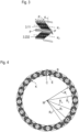
- the curve K has according to the Figure 4 its origin at a first point B on the first circular line K 1 and initially runs along the first circular line K 1 and then merges uninterruptedly into the second circular line K 2 in a transition region C. The curve K then continues along the circular line K 2 and ends at a second point E. Starting at the first point B, a structure 3.11 of the first conductor track 3.1 is followed by a structure 3.21 of the second conductor track 3.2 and so on along the curve K until the second point E is reached. No structures 3.101-3.132, 3.201-3.232 occur in the transition region C.
- the first circular line K 1 has its center point M on the axis A and has the radius R 1 .
- the second circular line K 2 also has its center point M on the axis A and has the radius R 2 .
- Both circular lines K 1 , K 2 are arranged concentrically around the center point M and the following applies: R 2 ⁇ R 1 .
- the structures 3.101-3.132, 3.201-3.232 of the first and second conductor tracks 3.1, 3.2 are arranged such that four adjacent structures within a circular sector S
- the four adjacent structures 3.104, 3.129; 3.204, 3.229 shown include the two structures 3.104, 3.129 of the first conductor track 3.1 and the two structures 3.204, 3.229 of the second conductor track 3.2, whereby the four adjacent structures 3.104, 3.129; 3.204, 3.229 together form an X-shaped formation F.
- the structures 3.104, 3.129 and 3.204, 3.229 of the same conductor track 3.1; 3.2 are arranged diagonally opposite one another within a formation F.
- the formation F shown occurs a total of 16 times distributed over 360° and extends concentrically and approximately evenly distributed along a circular line with the center M.
- Figure 6 shows a detailed view of the embodiment from Figure 5 .
- the arrangement of the structures 3.101-3.132, 3.201-3.232 of the first and second conductor tracks 3.1, 3.2 is X-shaped here.
- the structures 3.101-3.132, 3.201-3.232 of the first and second conductor tracks 3.1, 3.2 are arranged symmetrically, with a mirror or axial symmetry with respect to neighboring structures 3.101-3.132, 3.201-3.232 along the first circular line K 1 and the second circular line K 2 .
- the structures 3.101-3.132 of the first conductor track 3.1 and the structures 3.201-3.232 of the second conductor track 3.2 alternate along the first circular line K 1 and the second circular line K 2 with regard to their affiliation with the first and second conductor tracks 3.1, 3.2 and the angle ⁇ .
- the individual structures 3.101-3.132, 3.201-3.232 of a conductor track 3.1, 3.2 begin and end in a connecting section V, which can be designed differently with regard to length and shape.
- first conductor track 3.1 and the second conductor track 3.2 run in the circumferential direction in the connecting sections V.
- the path of the second conductor track 3.2 is designed such that it encloses the first conductor track 3.1 over the entire circumference of the substrate 2, ie the connecting sections V of the second conductor track 3.2 are located on the outside of the substrate 2, ie along a circular line with the outer radius R a and a circular line with the inner radius R i , whereas the connecting sections V of the first conductor track 3.1 are arranged on the inside, i.e. along a circular line with the central radius R m .
- the course of the first and second conductor tracks 3.1, 3.2 is always uninterrupted, both on the outgoing and the return path.
- the connecting sections V and structures 3.101-3.132 of the first conductor track 3.1 and the connecting sections V and structures 3.201-3.232 of the second conductor track 3.2 are approximately the same length in total and have approximately the same resistance.
- the connecting sections V of the second conductor track 3.2 run on the outside of the substrate 2 for the infeed, i.e. along a circular line with the outer radius R a , and for the return along a circular line with the inner radius R i .
- the connecting sections V of the first conductor track 3.1 run on the inside of the substrate 2 both for the infeed and the return between the structures 3.101-3.132, 3.201-3.232 of the first and second conductor tracks 3.2, 3.1, i.e. along a circular line with the central radius R m .
Landscapes
- Physics & Mathematics (AREA)
- General Physics & Mathematics (AREA)
- Force Measurement Appropriate To Specific Purposes (AREA)
Abstract
Description
- Die Erfindung betrifft eine Sensoreinrichtung zur Bestimmung einer Drehmomentbelastung gemäß dem Anspruch 1.
- Derartige Sensoren werden etwa zur Bestimmung der Drehmomentbelastung eines Maschinenteils verwendet.
- Konkreter kommen derartige Sensoreinrichtungen beispielsweise als Messgeräte zur Bestimmung der Drehmomentbelastung von Maschinenteilen in Robotergelenken zum Einsatz. In diesem Fall werden die Drehmomentmesswerte in der Regel einer Folgeelektronik über eine entsprechende Schnittstellenanordnung zugeführt.
- Sensoreinrichtungen in Form von Dehnungsmessstreifen, die direkt auf ein Messobjekt geklebt werden, sind bereits aus dem Stand der Technik bekannt. Dort wird die Änderung des elektrischen Widerstandes gemessen, der sich überwiegend rein geometrisch aus einer Längenänderung bei Dehnung ergibt. Um einen messbaren Effekt zu erzielen, handelt es sich bei den Dehnungsmessstreifen meist um mäanderförmige, flexible, dünne Metallleitungen. Dehnungsmessstreifen können zwar vielseitig eingesetzt werden, haben jedoch den entscheidenden Nachteil, dass diese nicht strukturspezifisch ausgebildet sind, wodurch ein Messergebnis mit nur unzureichender Genauigkeit erzielt wird. Außerdem werden Dehnmessstreifen in der Regel von Hand auf das Messobjekt geklebt, wodurch die Hauptspannungsrichtungen des Messobjekts meist nicht optimal getroffen werden. Durch das Aufkleben der Dehnmesstreifen auf das Messobjekt können sich zudem Alterungserscheinungen des Klebemittels negativ auf das Messergebnis auswirken.
- In der
JP 2020 - 201 046 A - Der Erfindung liegt die Aufgabe zugrunde, eine vergleichsweise einfache Sensoreinrichtung zu schaffen, durch welche eine Messung eines Drehmoments mit relativ hoher Genauigkeit ermöglicht wird.
- Diese Aufgabe wird erfindungsgemäß durch die Merkmale des Anspruchs 1 gelöst.
- Die erfindungsgemäße Sensoreinrichtung zur Drehmomentmessung umfasst ein Substrat, eine erste Leiterbahn und eine zweite Leiterbahn. Die erste Leiterbahn und die zweite Leiterbahn sind auf dem Substrat angeordnet und umfassen jeweils wenigstens einen Bereich mit Strukturen, welcher mäanderförmig ausgebildet ist. Die Strukturen der ersten Leiterbahn und die Strukturen der zweiten Leiterbahn sind jeweils über Verbindungsabschnitte, welche als Leiterbahnabschnitte ausgestaltet sind, kontinuierlich miteinander verbunden. Auf diese Weise wird eine Bestimmung der Drehmomentbelastung des Substrats durch die Sensoreinrichtung ermöglicht. Die Strukturen der ersten Leiterbahn und die Strukturen der zweiten Leiterbahn sind derart angeordnet, dass diese entlang einer Kurve alternierend verlaufen.
- Unter einer Sensoreinrichtung ist hierbei insbesondere eine passive Sensoreinrichtung zu verstehen, welche passive Sensoren beziehungsweise passive Bauteile enthält, deren Parameter durch die Drehmomentbelastung verändert werden. Durch elektronische Bauelemente werden diese Parameter in elektrische Signale, vorzugsweise innerhalb der Sensoreinrichtung, umgeformt. Für den Betrieb der Sensoreinrichtung wird eine von außen zugeführte Hilfsenergie insbesondere in Form elektrischer Energie benötigt. Als Parameter kann hier insbesondere der elektrische Widerstand beziehungsweise die elektrischen Widerstände der ersten und zweiten Leiterbahn dienen. Um den elektrischen Widerstand beziehungsweise eine Widerstandsänderung messen zu können, muss die Sensoranordnung - insbesondere die Strukturen der ersten und zweiten Leiterbahn - von einem elektrischen Strom durchflossen sein, sodass folglich die Sensoreinrichtung in Betrieb von außen mit elektrischer Energie versorgt werden muss. Insbesondere die Strukturen der ersten und zweiten Leiterbahn reagieren auf eine Drehmomentbelastung durch Längen- beziehungsweise Querschnittsänderungen, was Auswirkungen auf den elektrischen Widerstand der ersten und zweiten Leiterbahn hat.
- Das zu messende Drehmoment kann insbesondere ein Torsionsmoment sein.
- Unter einem Substrat ist hierbei ein Bauteil zu verstehen, welches beispielsweise in Form einer Kreisscheibe oder einem Kreisring bereitgestellt ist und das insbesondere einen metallenen Werkstoff umfasst, etwa Stahl, und das vorzugsweise eine isolierende Schicht an einer Fläche aufweist. Unter einer Kurve ist eine Kurve im mathematischen Sinne zu verstehen, welche primär entlang einer Längs- oder Umfangsrichtung des Substrats verläuft.
- Unter einer Struktur ist wenigstens ein Teilabschnitt der ersten Leiterbahn oder zweiten Leiterbahn zu verstehen, welcher einen mäanderförmigen Verlauf mit mehreren parallel ausgerichteten Schlingen umfasst. Mehrere Strukturen ein und derselben Leiterbahn sind unterbrechungsfrei durch Verbindungsabschnitte miteinander verbunden. Die Strukturen der ersten und zweiten Leiterbahn können heterogen-alternierend angeordnet werden, indem eine Vielzahl von Strukturen in Längs- oder Umfangsrichtung angeordnet und in Reihe geschaltet sind.
- Unter einem alternierenden Verlauf ist ein Wechsel zwischen den Strukturen der ersten Leiterbahn und den Strukturen der zweiten Leiterbahn entlang der Kurve zu verstehen, wobei wenigstens eine Struktur der ersten Leiterbahn auf eine Struktur der zweiten Leiterbahn folgt.
- Mit Vorteil ist die erfindungsgemäße Sensoreinrichtung derart angeordnet, dass die Kurve unterbrechungsfrei und wenigstens abschnittsweise entlang einer ersten Kreislinie hingeführt und wenigstens abschnittsweise entlang einer zweiten Kreislinie zu ihrem Ursprung rückgeführt wird.
- Dabei sind die erste Kreislinie und die zweite Kreislinie konzentrisch angeordnet, wobei zwar beide einen identischen Mittelpunkt, jedoch unterschiedliche Radien besitzen.
- Unter einer unterbrechungsfreien Hin- und Rückführung ist ein kontinuierlicher und zusammenhängender Verlauf der ersten Leiterbahn bzw. der zweiten Leiterbahn von deren Ursprung entlang des Substrats und zurück zum Ursprung zu verstehen, wobei der Verlauf ohne Abzweigungen, Kreuzungen oder Unterbrechungen charakterisiert ist.
- Der Ursprung der Kurve ist der Ausgangspunkt des Kurvenverlaufs der Kurve. Somit ist der Ursprung der Anfangspunkt oder der Endpunkt der ersten beziehungsweise der zweiten Leiterbahn. Die erste beziehungsweise die zweite Leiterbahn ist dort beispielsweise mit einem elektronischen Bauelement kontaktiert. Zwischen der ersten und zweiten Leiterbahn kann im Ursprung ein Mittelabgriff vorgesehen sein.
- In weiterer vorteilhafter Ausgestaltung erstrecken sich die erste Kreislinie und die zweite Kreislinie jeweils konzentrisch zu einem Mittelpunkt und in einer Umfangsrichtung des Substrats.
- Eine weitere vorteilhafte Weiterbildung umfasst eine erfindungsgemäße Sensoreinrichtung, wobei das Substrat relativ um eine Achse, welche durch den Mittelpunkt verläuft, in der Umfangsrichtung drehbar und ergänzend oder alternativ verwindbar angeordnet ist.
- "Verwindbar" bedeutet, dass ein elastischer Körper - insbesondere das Substrat - durch Drehmomente eine Verformung erfährt und somit einen (reversibel) verwundenen bzw. verdrillten Zustand einnimmt.
- Die Achse, welche durch den Mittelpunkt verläuft, verläuft zudem orthogonal zur Sensorvorrichtung, insbesondere zur ersten oder zweiten Kreislinie oder zum Substrat.
- Mit Vorteil ist die erfindungsgemäße Sensoreinrichtung derart ausgestaltet, dass die Strukturen der ersten Leiterbahn und die Strukturen der zweiten Leiterbahn zueinander symmetrisch angeordnet sind.
- Hierbei ist zum einen eine Symmetrie hinsichtlich benachbarter Strukturen entlang der Kurve, insbesondere in Kurvenabschnitten, welche auf der ersten Kreislinie oder der zweiten Kreislinie angeordnet sind, gemeint. Beispielsweise in Form einer Achsen- bzw. Spiegelsymmetrie. Alternativ oder ergänzend kann zudem eine Punktsymmetrie vorliegen. Hierbei liegen je zwei benachbarte Strukturen im Abschnitt der ersten Kreislinie der Kurve und je zwei benachbarte Strukturen im Abschnitt der zweiten Kreislinie der Kurve punktsymmetrisch zueinander, wobei das Paar im ersten Abschnitt der ersten Kreislinie und das Paar im Abschnitt der zweiten Kreislinie ebenfalls symmetrisch zueinander liegen. Die Punktsymmetrie bezieht sich demnach hier auf einen Punkt, der radial mittig zwischen der ersten Kreislinie und der zweiten Kreislinie liegt.
- Mit Vorteil sind die Strukturen der erfindungsgemäßen Sensoreinrichtung derart angeordnet, dass vier benachbarte Strukturen innerhalb eines Kreissektors der Sensoreinrichtung liegen. Die vier benachbarten Strukturen umfassen dabei zwei Strukturen der ersten Leiterbahn und zwei Strukturen der zweiten Leiterbahn, wobei die vier benachbarten Strukturen gemeinsam eine X-förmige oder rautenförmige Formation ausbilden.
- Unter einem Kreissektor ist die kleinere Teilfläche einer Kreis- oder Ringscheibe zu verstehen - insbesondere bzgl. des Substrats - welche durch einen Kreisbogen, zwei Kreisradien und unter einem Mittelpunktswinkel definiert wird. Hierbei kann die Sensoreinrichtung einen oder mehrere Kreissektor(en) aufweisen, wobei innerhalb jedes Kreissektors vier Sensorstrukturen angeordnet sind. Sind mehrere Kreissektoren auf dem Substrat ausgebildet, können diese entweder gleich oder beliebig über die 360° der Kreis- oder Ringscheibe verteilt sein.
- Unter einer Formation ist eine geometrische Anordnung von vier benachbarten Strukturen zu verstehen. Die vier benachbarten Strukturen liegen hierbei in einem Kreissektor, wobei sich diese vier Strukturen aus je einer Struktur der ersten und zweiten Leiterbahn auf je der ersten und zweiten Kreislinie zusammensetzt. Insbesondere Strukturen der gleichen Leiterbahn können sich dabei diagonal gegenüber liegen.
- Hierbei kann die Formation derart ausgebildet sein, dass diese beispielsweise dem 24. Buchstaben "X" des modernen lateinischen Alphabets oder einer geometrischen Raute ("<>") ähnelt.
- In vorteilhafter Weise ist die zweite Leiterbahn derart angeordnet, dass diese die erste Leiterbahn umschließt.
- Hierbei ist mit einer umschließenden Anordnung gemeint, dass die Bahnführung der zweiten Leiterbahn derart gestaltet ist, dass die erste und zweite Leiterbahn in einer Ebene beziehungsweise in einer Lage auf dem Substrat liegen, wobei die erste Leiterbahn immer von wenigstens zwei Seiten von der zweiten Leiterbahn bzw. deren Strukturen und Verbindungsabschnitte eingefasst ist. Gleichzeitig schneiden, kreuzen oder berühren sich die erste und zweite Leiterbahn nicht.
- Die Verbindungsabschnitte der ersten Leiterbahn und die Verbindungsabschnitte der zweiten Leiterbahn sind näherungsweise gleich lang und haben näherungsweise den gleichen Widerstand.
- Mit Vorteil ist die erfindungsgemäße Sensoreinrichtung so ausgestaltet, dass die erste Leiterbahn und die zweite Leiterbahn additiv auf das Substrat aufgetragen sind.
- Im Zuge der Herstellung eines derartigen additiven Aufbaus werden Schichten großflächig oder strukturiert (z. B. mit einem Lift-off-Verfahren) auf dem Substrat aufgebracht. Dies geschieht etwa durch eine chemische Reaktion oder durch eine Kondensation von gasförmigen Stoffen auf die Oberfläche des Substrats. Alternativ kann der additive Aufbau auch durch Abscheidung aus einer flüssigen Phase erzeugt werden. Insbesondere ist unter dem Begriff "additiver Aufbau" nicht zu verstehen, dass die Leiterbahnen auf dem Substrat aufgeklebt sind.
- Mit Vorteil ist die erfindungsgemäße Sensoreinrichtung derart ausgestaltet, dass das Substrat wenigstens ein erstes Mittel zur Einleitung einer Drehmomentbelastung und ergänzend oder alternativ wenigstens ein zweites Mittel zur Ausleitung einer Drehmomentbelastung umfasst.
- Die Mittel zur Ein- bzw. Ausleitung einer Drehmomentbelastung können in Form einer mechanisch wirkenden bzw. nutzbaren Ausgestaltung des Substrats realisiert sein, beispielsweise in Form einer oder mehrerer Bohrungen. Alternativ oder ergänzend können die Mittel in Form von gleichmäßig oder ungleichmäßig verteilten Zähnen, Zacken oder Zinken ausgestaltet sein. Diese können beispielsweise an einem Außen- oder einem Innenumfang der Kreis- oder Ringscheibe angebracht sein, wobei diese entweder nach außen oder innen abstehen können (wie bei einem Zahnrad) oder unter einem Winkel auf der Oberfläche der Kreis- oder Ringscheibe angebracht sein.
- Mit Vorteil ist die erfindungsgemäße Sensoreinrichtung derart ausgestaltet, dass die Drehmomentbelastung durch Bestimmung des Widerstands der ersten Leiterbahn und ergänzend oder alternativ der zweiten Leiterbahn bestimmbar ist.
- In weiterer Ausgestaltung der Erfindung umfassen die erste Leiterbahn und die zweite Leiterbahn je eine identische Anzahl an Strukturen, wobei diese gemäß einer Brückenschaltung verschaltet sind.
- Insbesondere kann eine Halbbrücke implementiert werden, die beispielsweise die Änderung der Widerstandsdifferenz über eine Spannungsänderung bestimmt.
- Mit Vorteil ist auf dem Substrat zumindest ein elektronisches Bauelement angeordnet, durch welches Signale, die von der ersten Leiterbahn und ergänzend oder alternativ von der zweiten Leiterbahn erzeugbar sind, weiterverarbeitbar sind. Insbesondere kann die Weiterverarbeitung durch elektronische Bauelemente zur Signalverstärkung und/oder -digitalisierung erfolgen.
- In weiterer Ausgestaltung sind das Substrat aus Metall - insbesondere Stahl - und die Leiterbahnen aus Metall - insbesondere Aluminium, Kupfer, Konstantan oder einer NiCr-Legierung - hergestellt.
- Mit Vorteil sind das Substrat und die Leiterbahnen aus unterschiedlichen Metallen hergestellt. Beispielsweise kann das Substrat aus Stahl und die erste Leiterbahn sowie die zweite Leiterbahn aus Kupfer hergestellt sein.
- In vorteilhafter Ausgestaltung der Erfindung weisen die Strukturen jeweils mehrere Abschnitte auf, in denen die entsprechende Leiterbahn gerade oder gekrümmt parallel verläuft.
- In weiterer Ausgestaltung der Erfindung ist der Krümmungsradius der Leiterbahnen in den Abschnitten in Abhängigkeit vom Abstand zur Achse unterschiedlich. Insbesondere wird der Krümmungsradius mit zunehmendem Abstand zur Achse größer.
- Mit Vorteil schneiden die Strukturen in den Abschnitten die Kreislinien, die unterschiedliche Radien aufweisen können, aber deren Mittelpunkt auf der Achse liegt, jeweils in einem gleich großen Winkel. Insbesondere ist der Winkel zwischen der Tangente auf der entsprechenden Kreislinie und der Tangente der Struktur im Schnittpunkt in den Abschnitten an verschiedenen Stellen stets gleich groß. Die Strukturen verlaufen mit Vorteil in den Abschnitten jeweils gemäß einer logarithmischen Spirale.
- In vorteilhafter Ausgestaltung der Erfindung hat der Winkel einen Betrag zwischen 20° und 70°, insbesondere zwischen 30° und 60°, vorteilhafterweise zwischen 40° und 50°.
- Die Erfindung wird nachstehend auch hinsichtlich weiterer Merkmale und Vorteile anhand der Beschreibung von Ausführungsbeispielen und unter Bezugnahme auf die beiliegenden, schematischen Zeichnungen näher erläutert. Die entsprechenden Figuren zeigen im Einzelnen:
-
- Fig. 1:
- zeigt ein Ausführungsbeispiel in perspektivischer Darstellung einer Sensoreinrichtung, gekoppelt an eine Antriebseinheit;
- Fig. 2:
- zeigt eine Draufsicht auf die Sensoreinrichtung;
- Fig. 3:
- zeigt eine Detailansicht der Strukturen der Sensoreinrichtung;
- Fig. 4:
- zeigt eine Gesamtansicht der Strukturen einer Sensoreinrichtung;
- Fig. 5:
- zeigt eine Gesamtansicht der Strukturen und der Formation in einem Kreissektor einer Sensoreinrichtung;
- Fig. 6:
- zeigt einen Ausschnitt der Strukturen aus
Fig. 5 der Sensoreinrichtung. -
Figur 1 zeigt ein erstes Ausführungsbeispiel in vereinfachter Darstellung der erfindungsgemäßen Sensoreinrichtung 1, gekoppelt an eine Antriebseinheit 5. Eine solche Anordnung findet beispielsweise Anwendung in Roboterachsen von Industrierobotern. Die Sensoreinrichtung 1 steht mit der Antriebseinheit 5 in Verbindung, wobei das Substrat der Sensoreinrichtung 1 an die Antriebseinheit 5 gekoppelt oder angeflanscht ist. Als Reaktion auf eine tangentiale Krafteinleitung in die Sensoreinrichtung 1 durch die Antriebseinheit 5 kann insbesondere auf das Substrat 2 ein Drehmoment wirken, wodurch es zum geringfügigen Verwinden der Sensoreinrichtung 1 beziehungsweise des Substrats 2 kommt. Das hierbei auftretende Drehmoment kann von der Sensoreinrichtung 1 erfasst und weiterverarbeitet werden. - In der
Figur 2 ist eine Draufsicht auf die Sensoreinrichtung 1 gezeigt. Die Sensoreinrichtung 1 umfasst das Substrat 2, welches beispielsweise aus einem (insbesondere faserverstärktem) Epoxid-Harz, aus kohlenstofffaserverstärktem Kunststoff oder aus einem Metall, insbesondere Stahl, besteht. Für Befestigungszwecke weist die Sensoreinrichtung 1 beziehungsweise das Substrat 2 Bohrungen 2.1 und Zähne 2.2 auf, wobei die Bohrungen 2.1 entlang eines inneren Durchmessers und die Zähne 2.2 entlang eines äußeren Durchmessers konzentrisch zur Achse A angeordnet sind. Auf diese Weise kann die Sensoreinrichtung 1 unter Zuhilfenahme von Schrauben oder Nieten verdrehsicher an einem Bauteil, beispielsweise einem Flansch und einer Nabe einer Antriebseinheit 5, angebracht werden. Die Sensoreinrichtung 1 umfasst zudem eine erste und zweite Leiterbahn 3.1, 3.2, welche durch einen additiven Aufbau, insbesondere mit Hilfe eines Fotolithografie-Prozesses, aufgebracht sind. Falls das Substrat 2 aus einem Metall-Werkstoff, etwa Stahl, hergestellt ist, wird zwischen den Leiterbahnen 3.1, 3.2 und dem Substrat 2 eine elektrisch isolierende Kunststoffschicht, beispielsweise aus Polyimid, bereitgestellt. - Die Sensoreinrichtung 1 ist im Wesentlichen ring- bzw. kreisförmig ausgebildet und bezüglich der Achse A zentrisch angeordnet. Außerdem sind die Leiterbahnen 3.1, 3.2 in einer Ebene angeordnet, die orthogonal zur Achse A orientiert ist. Insbesondere ist die Sensoreinrichtung 1 bezüglich eines Punktes auf der Achse A punktsymmetrisch ausgestaltet. Die Strukturen 3.101-3.132, 3.201-3.232 (siehe
Figur 6 ) der ersten und zweiten Leiterbahn 3.1, 3.2 bestehen beispielsweise aus Kupfer oder Konstantan. - Die Sensoreinrichtung 1 kann mit elektrischer Energie versorgt werden. Dies kann beispielsweise über ein Kabel (bei Begrenzung der möglichen Anzahl an Umdrehungen), über einen Schleifring oder drahtlos erfolgen. Beim Betreiben der Sensoreinrichtung 1 fließt ein definierter Strom durch die Sensoreinrichtung 1. Dadurch, dass das Drehmoment durch die Sensoreinrichtung 1 bzw. das Substrat 2 hindurch geleitet wird, kommt es zur Verformung der Sensoreinrichtung 1. In Abhängigkeit von der Verformung des Substrats 2 aufgrund einer Drehmomentbelastung (insbesondere einer Torsionsbelastung) kommt es in Folge von lokalen Dehnungserscheinungen insbesondere in den Strukturen 3.101-3.132, 3.201-3.232 zu einer Längenänderung der Leiterbahnen 3.1, 3.2. Dies hat wiederum eine Änderung des Widerstands zur Folge. Durch Nutzung dieses Effekts kann durch die Sensoreinrichtung 1 eine Drehmomentbelastung (insbesondere eine Torsionsbelastung) des Substrats 2 um die Achse A bestimmt werden. Durch die elektronischen Bauelemente 4 werden Signale erzeugt, verarbeitet und bei Bedarf zu einer Folgeelektronik übertragen.
- Die Strukturen 3.101-3.132, 3.201-3.232 der Leiterbahnen 3.1, 3.2 weisen gemäß der Detailansicht in
Figur 3 jeweils mehrere Abschnitte P auf, in denen die Leiterbahnen 3.1, 3.2 gerade verlaufen. Die Leiterbahnen 3.1, 3.2 schneiden in den Abschnitten P eine der Kreislinien K1, K2 so, dass immer der Mittelpunkt jedes Abschnitts P beziehungsweise die jeweilige Abschnittshalbierende jedes Abschnitts P auf der ersten Kreislinie K1 beziehungsweise auf der zweiten Kreislinie K2 liegt. Im vorgestellten Ausführungsbeispiel schließt der Verlauf des jeweiligen geraden Abschnitts P und eine in radialer Richtung verlaufende Gerade durch den Mittelpunkt des Abschnitts P einen Winkel α mit einem Betrag von 45° ein. - Alternativ können die Leiterbahnen 3.1, 3.2 auch gekrümmt und parallel verlaufen (in den Figuren nicht dargestellt). In diesem Fall der alternativen Ausführungsform verlaufen die Leiterbahnen 3.1, 3.2 dann in den Bereichen der Abschnitte P entlang paralleler Spirallinien, so dass innerhalb der Abschnitte P der Krümmungsradius der Leiterbahnen 3.1, 3.2 in Abhängigkeit vom Abstand zur Achse A unterschiedlich ist. Der Winkel α kann gemäß des alternativen Ausführungsbeispiels ebenfalls betragsmäßig 45° betragen. Folglich verlaufen die Leiterbahnen 3.1, 3.2 dann in den Abschnitten P jeweils gemäß den Gesetzmäßigkeiten zweier logarithmischen Spiralen. Jede Tangente an einer der Kreislinien K1, K2 schneidet eine der logarithmischen Spiralen stets unter dem gleichen Winkel α (isogonale Trajektorien), wobei diese Eigenschaft für beliebige Kreislinien mit unterschiedlichen Radien, deren gemeinsamer Mittelpunkt M auf der Achse A liegt, zutrifft. Die Leiterbahnen 3.1, 3.2 verlaufen in diesem Fall in den Abschnitten P daher auch gemäß gleichwinkliger Spiralen.
- Die Leiterbahnen 3.1, 3.2 umfassen mehrere Strukturen 3.101-3.132, 3.201-3.232, welche alternierend entlang einer Kurve K angeordnet sind. Die Kurve K besitzt gemäß der
Figur 4 ihren Ursprung in einem ersten Punkt B auf der ersten Kreislinie K1 und verläuft zunächst entlang der ersten Kreislinie K1 und geht in einem Übergangsbereich C unterbrechungsfrei auf die zweite Kreislinie K2 über. Die Kurve K verläuft anschließend weiter entlang der Kreislinie K2 und endet in einem zweiten Punkt E. Beginnend im ersten Punkt B folgt auf eine Struktur 3.11 der ersten Leiterbahn 3.1 eine Struktur 3.21 der zweiten Leiterbahn 3.2 und so weiter entlang der Kurve K, bis der zweite Punkt E erreicht ist. Im Übergangsbereich C treten keine Strukturen 3.101-3.132, 3.201-3.232 auf. Die erste Kreislinie K1 hat ihren Mittelpunkt M auf der Achse A und besitzt den Radius R1. Die zweite Kreislinie K2 hat ihren Mittelpunkt M ebenfalls auf der Achse A und besitzt den Radius R2. Beide Kreislinien K1, K2 sind konzentrisch um den Mittelpunkt M angeordnet und es gilt: R2 < R1. - Wie den
Figuren 5 und 6 entnommen werden kann, sind die Strukturen 3.101-3.132, 3.201-3.232 der ersten und zweiten Leiterbahn 3.1, 3.2 derart angeordnet, dass vier benachbarte Strukturen innerhalb eines Kreissektors S liegen. Die vier gezeigten benachbarten Strukturen 3.104, 3.129; 3.204, 3.229 umfassen dabei die zwei Strukturen 3.104, 3.129 der ersten Leiterbahn 3.1 und die zwei Strukturen 3.204, 3.229 der zweiten Leiterbahn 3.2, wobei die vier benachbarten Strukturen 3.104, 3.129; 3.204, 3.229 gemeinsam eine X-förmige Formation F ausbilden. Dabei sind die Strukturen 3.104, 3.129 bzw. 3.204, 3.229 einer gleichen Leiterbahn 3.1; 3.2 innerhalb einer Formation F diagonal gegenüber liegend angeordnet. Die inFigur 5 dargestellte Formation F kommt insgesamt 16-mal über 360° verteilt vor und erstreckt sich konzentrisch und näherungsweise gleichverteilt entlang einer Kreislinie mit dem Mittelpunkt M. -
Figur 6 zeigt eine Detailansicht des Ausführungsbeispiels ausFigur 5 . Die Anordnung der Strukturen 3.101-3.132, 3.201-3.232 der ersten und zweiten Leiterbahn 3.1, 3.2 erfolgt hier X-förmig. Die Strukturen 3.101-3.132, 3.201-3.232 der ersten und zweiten Leiterbahn 3.1, 3.2 sind symmetrisch angeordnet, wobei eine Spiegel- bzw. Achsensymmetrie hinsichtlich benachbarter Strukturen 3.101-3.132, 3.201-3.232 entlang der ersten Kreislinie K1 sowie der zweiten Kreislinie K2 besteht. Darüber hinaus alternieren die Strukturen 3.101-3.132 der ersten Leiterbahn 3.1 und die Strukturen 3.201-3.232 der zweiten Leiterbahn 3.2 entlang der ersten Kreislinie K1 bzw. der zweiten Kreislinie K2 hinsichtlich ihrer Zugehörigkeit zur ersten und zweiten Leiterbahn 3.1, 3.2 und dem Winkel α. So besitzen beispielsweise die Strukturen 3.101-3.132 der ersten Leiterbahn 3.1 entlang der ersten Kreislinie K1 den Winkel α 1 = 45° und die Strukturen 3.201-3.232 der zweiten Leiterbahn 3.2 entlang der ersten Kreislinie K1 den Winkel α 2 = -45°. Die einzelnen Strukturen 3.101-3.132, 3.201-3.232 einer Leiterbahn 3.1, 3.2 beginnen und enden in einem Verbindungsabschnitt V, wobei dieser hinsichtlich Länge und Form unterschiedlich ausgestaltet sein kann. Insbesondere verlaufen die erste Leiterbahn 3.1 und die zweite Leiterbahn 3.2 in den Verbindungsabschnitten V in Umfangsrichtung. Die Bahnführung der zweiten Leiterbahn 3.2 ist so ausgestaltet, dass diese die erste Leiterbahn 3.1 über den gesamten Umfang des Substrats 2 umschließt, d. h. die Verbindungsabschnitte V der zweiten Leiterbahn 3.2 sind auf dem Substrat 2 außen liegend, d. h. entlang einer Kreislinie mit dem Außenradius Ra und einer Kreislinie mit dem Innenradius Ri angeordnet, wohingegen die Verbindungsabschnitte V der ersten Leiterbahn 3.1 innen liegend angeordnet sind, d. h entlang einer Kreislinie mit dem Mittelradius Rm. Der Verlauf der ersten und zweiten Leiterbahn 3.1, 3.2 erfolgt stets unterbrechungsfrei, sowohl bei der Hinführung als auch bei der Rückführung. - Die Verbindungsabschnitte V und Strukturen 3.101-3.132 der ersten Leiterbahn 3.1 und die Verbindungsabschnitte V und Strukturen 3.201-3.232 der zweiten Leiterbahn 3.2 sind in Summe näherungsweise gleich lang und haben näherungsweise den gleichen Widerstand. Dabei verlaufen die Verbindungsabschnitte V der zweiten Leiterbahn 3.2 auf dem Substrat 2 bei der Hinführung außen liegend, d. h. entlang einer Kreislinie mit dem Außenradius Ra und bei der Rückführung entlang einer Kreislinie mit dem Innenradius Ri. Die Verbindungsabschnitte V der ersten Leiterbahn 3.1 verlaufen auf dem Substrat 2 sowohl bei der Hinführung als auch bei der Rückführung zwischen den Strukturen 3.101-3.132, 3.201-3.232 der ersten und zweiten Leiterbahn 3.2, 3.1 innen liegend, d. h. entlang einer Kreislinie mit dem Mittelradius Rm. Es gilt: Ri + Ra = 2 · Rm. Hierdurch ist ein gleichmäßiger Temperatureintrag auf die erste und zweite Leiterbahn 3.1, 3.2 bei einem einlagigen Aufbau gewährleistet, da sich sowohl die Strukturen 3.101-3.132, 3.201-3.232 der ersten und zweiten Leiterbahn 3.1, 3.2 als auch die Verbindungsabschnitte V im Mittel auf einer virtuellen Kreislinie mit identischem Radius befinden. Dadurch besitzen die erste und zweite Leiterbahn 3.1, 3.2 selbst bei Temperaturgradienten von innen nach außen auf dem Substrat 2 im Mittel die gleiche Temperatur. Durch die über den Umfang U des Substrats 2 verteilte, vielfache Anordnung der Strukturen 3.101-3.132, 3.201-3.232 können zudem parasitäre Einflüsse durch Nutzung von Symmetrieeffekten besser kompensiert werden.
-
- 1
- Sensoreinrichtung
- 2
- Substrat
- 2.1
- Erstes Mittel
- 2.2
- Zweites Mittel
- 3.1
- Erste Leiterbahn
- 3.101-3.132
- Strukturen der ersten Leiterbahn
- 3.2
- Zweite Leiterbahn
- 3.201-3.232
- Strukturen der zweiten Leiterbahn
- 4
- Elektronisches Bauelement
- 5
- Antriebseinheit
- A
- Achse
- U
- Umfangsrichtung
- K
- Kurve
- K1
- Erste Kreislinie
- K2
- Zweite Kreislinie
- M
- Mittelpunkt
- R1
- Erster Radius
- R2
- Zweiter Radius
- Ra
- Außenradius
- Ri
- Innenradius
- Rm
- Mittelradius
- B
- Erster Punkt
- E
- Zweiter Punkt
- C
- Übergangsbereich
- V
- Verbindungsabschnitt
- S
- Kreissektor
- F
- Formation
- P
- Abschnitt
- α
- Winkel α
Claims (19)
- Sensoreinrichtung (1) zur Drehmomentmessung umfassend ein Substrat (2), eine erste Leiterbahn (3.1) und eine zweite Leiterbahn (3.2),wobei die erste Leiterbahn (3.1) und die zweite Leiterbahn (3.2) auf dem Substrat (2) angeordnet sind und jeweils wenigstens einen Bereich mit Strukturen (3.101-3.132; 3.201-3.232) umfassen, welche mäanderförmig ausgebildet sind,wobei die Strukturen (3.101-3.132) der ersten Leiterbahn (3.1) und die Strukturen (3.201-3.232) der zweiten Leiterbahn (3.2) jeweils über Verbindungsabschnitte (V) miteinander verbunden sind, sodass durch die Sensoreinrichtung (1) eine Drehmomentbelastung des Substrats (2) bestimmbar ist,wobei die Strukturen (3.101-3.132) der ersten Leiterbahn (3.1) und die Strukturen (3.201-3.232) der zweiten Leiterbahn (3.2) derart angeordnet sind, dass diese entlang einer Kurve (K) alternierend verlaufen.
- Sensoreinrichtung (1) gemäß Anspruch 1, wobei die Kurve (K) derart verläuft, dass die Kurve (K) unterbrechungsfrei und wenigstens abschnittsweise entlang einer ersten Kreislinie (K1) hingeführt und wenigstens abschnittsweise entlang einer zweiten Kreislinie (K2) zu ihrem Ursprung rückgeführt wird.
- Sensoreinrichtung (1) gemäß Anspruch 2, wobei sich die erste Kreislinie (K1) und die zweite Kreislinie (K2) jeweils konzentrisch zu einem Mittelpunkt (M) und in eine Umfangsrichtung (U) des Substrats (2) erstrecken.
- Sensoreinrichtung (1) gemäß einem der vorhergehenden Ansprüche, wobei das Substrat (2) relativ um eine Achse (A), welche durch den Mittelpunkt (M) verläuft, und in die Umfangsrichtung (U) drehbar und/oder verwindbar angeordnet ist.
- Sensoreinrichtung (1) einem der vorhergehenden Ansprüche, wobei die Strukturen (3.101-3.132; 3.201-3.232) der ersten Leiterbahn (3.1) und der zweiten Leiterbahn (3.2) zueinander symmetrisch angeordnet sind.
- Sensoreinrichtung (1) gemäß einem der vorhergehenden Ansprüche, wobei in einem Kreissektor (S) benachbarte Strukturen (3.101-3.132; 3.201-3.232), bestehend aus Strukturen (3.101-3.132) der ersten Leiterbahn (3.1) und Strukturen (3.201-3.232) der zweiten Leiterbahn (3.2), eine X-förmige oder rautenförmige Formation (F) ausbilden.
- Sensoreinrichtung (1) gemäß einem der vorhergehenden Ansprüche, wobei die zweite Leiterbahn (3.2) derart angeordnet ist, dass diese die erste Leiterbahn (3.1) umschließt.
- Sensoreinrichtung (1) gemäß einem der vorhergehenden Ansprüche, wobei die erste Leiterbahn (3.1) und zweite Leiterbahn (3.2) additiv auf das Substrat (2) aufgetragen sind.
- Sensoreinrichtung (1) gemäß einem der vorhergehenden Ansprüche, wobei das Substrat (2) wenigstens ein erstes Mittel (2.1) zur Einleitung einer Drehmomentbelastung und wenigstens ein zweites Mittel (2.2) zur Ausleitung einer Drehmomentbelastung umfasst.
- Sensoreinrichtung (1) gemäß einem der vorhergehenden Ansprüche, wobei die Drehmomentbelastung durch Bestimmung des Widerstands der ersten Leiterbahn (3.1) und/oder der zweiten Leiterbahn (3.2) bestimmbar ist.
- Sensoreinrichtung (1) gemäß einem der vorhergehenden Ansprüche, wobei die erste Leiterbahn (3.1) und zweite Leiterbahn (3.2) je eine identische Anzahl an Strukturen (3.101-3.132; 3.201-3.232) umfassen, wobei diese gemäß einer Brückenschaltung verschaltet sind.
- Sensoreinrichtung (1) gemäß einem der vorhergehenden Ansprüche, wobei auf dem Substrat (2) zumindest ein elektronisches Bauelement (4) angeordnet ist, durch welches Signale, die von der ersten und/oder der zweiten Leiterbahn (3.1; 3.2) erzeugbar sind, weiterverarbeitbar sind.
- Sensoreinrichtung (1) gemäß einem der vorhergehenden Ansprüche, wobei das Substrat (2) und die Leiterbahnen (3.1; 3.2) aus Metall hergestellt sind.
- Sensoreinrichtung (1) gemäß Anspruch 13, wobei das Substrat (2) und die Leiterbahnen (3.1; 3.2) aus unterschiedlichen Metallen hergestellt sind.
- Sensoreinrichtung (1) gemäß einem der vorhergehenden Ansprüche, wobei die Strukturen (3.101-3.132; 3.201-3.232) jeweils mehrere Abschnitte (P) aufweisen, in denen die Leiterbahnen (3.1; 3.2) gerade oder gekrümmt parallel verlaufen.
- Sensoreinrichtung (1) gemäß einem der vorhergehenden Ansprüche, wobei die Strukturen (3.101-3.132; 3.201-3.232) jeweils mehrere Abschnitte (P) aufweisen, in denen die Leiterbahnen (3.1; 3.2) gekrümmt mit einem Krümmungsradius parallel verlaufen, wobei der Krümmungsradius in Abhängigkeit vom Abstand zur Achse (A) unterschiedlich ist.
- Sensoreinrichtung (1) gemäß einem der Ansprüche 15 oder 16, wobei die Strukturen (3.101-3.132; 3.201-3.232) in den Abschnitten (P) eine der Kreislinien (K1; K2) in einem betragsmäßig identischen Winkel (α) schneidet.
- Sensoreinrichtung (1) gemäß dem Anspruch 17, wobei der Winkel (α) einen Betrag zwischen 20° und 70° annimmt.
- Sensoreinrichtung (1) gemäß einem der vorhergehenden Ansprüche, wobei die Verbindungsabschnitte (V) der zweiten Leiterbahn (3.2) bei der Hinführung entlang einer Kreislinie mit einem Außenradius (Ra) und bei der Rückführung entlang einer Kreislinie mit einem Innenradius (Ri) verlaufen und wobei die Verbindungsabschnitte (V) der ersten Leiterbahn (3.1) sowohl bei der Hinführung als auch bei der Rückführung entlang einer Kreislinie mit dem Mittelradius (Rm) verlaufen, wobei gilt: Ri + Ra = 2 · Rm.
Priority Applications (5)
| Application Number | Priority Date | Filing Date | Title |
|---|---|---|---|
| EP23166482.2A EP4443124B1 (de) | 2023-04-04 | 2023-04-04 | Sensoreinrichtung |
| DE102024000384.3A DE102024000384A1 (de) | 2023-04-04 | 2024-02-06 | Sensoreinrichtung |
| US18/617,715 US20240337547A1 (en) | 2023-04-04 | 2024-03-27 | Sensor device |
| JP2024058519A JP2024148163A (ja) | 2023-04-04 | 2024-04-01 | センサ機構 |
| CN202410403136.0A CN118776722A (zh) | 2023-04-04 | 2024-04-03 | 传感器装置 |
Applications Claiming Priority (1)
| Application Number | Priority Date | Filing Date | Title |
|---|---|---|---|
| EP23166482.2A EP4443124B1 (de) | 2023-04-04 | 2023-04-04 | Sensoreinrichtung |
Publications (2)
| Publication Number | Publication Date |
|---|---|
| EP4443124A1 true EP4443124A1 (de) | 2024-10-09 |
| EP4443124B1 EP4443124B1 (de) | 2026-01-21 |
Family
ID=85873661
Family Applications (1)
| Application Number | Title | Priority Date | Filing Date |
|---|---|---|---|
| EP23166482.2A Active EP4443124B1 (de) | 2023-04-04 | 2023-04-04 | Sensoreinrichtung |
Country Status (5)
| Country | Link |
|---|---|
| US (1) | US20240337547A1 (de) |
| EP (1) | EP4443124B1 (de) |
| JP (1) | JP2024148163A (de) |
| CN (1) | CN118776722A (de) |
| DE (1) | DE102024000384A1 (de) |
Citations (4)
| Publication number | Priority date | Publication date | Assignee | Title |
|---|---|---|---|---|
| JP2004198400A (ja) * | 2002-09-17 | 2004-07-15 | Harmonic Drive Syst Ind Co Ltd | 波動歯車装置のトルク検出装置 |
| JP2020201046A (ja) | 2019-06-06 | 2020-12-17 | 日本電産シンポ株式会社 | トルク検出センサおよび動力伝達装置 |
| JP2021096105A (ja) * | 2019-12-16 | 2021-06-24 | 日本電産シンポ株式会社 | 回転角度検出センサ、トルク検出センサ、および動力伝達装置 |
| DE102022206333A1 (de) * | 2021-06-23 | 2022-12-29 | Nidec-Shimpo Corporation | Sensor und antriebskraftübertragungsvorrichtung |
Family Cites Families (10)
| Publication number | Priority date | Publication date | Assignee | Title |
|---|---|---|---|---|
| DE10342479B4 (de) * | 2002-09-17 | 2016-03-31 | Harmonic Drive Systems Inc. | Drehmomentdetektionsvorrichtung für Wellengetriebe |
| DE202016008595U1 (de) * | 2016-10-17 | 2018-07-26 | Franka Emlka Gmbh | Drehmomentsensorvorrichtung zum Erfassen von Drehmomenten |
| DE102017210655B4 (de) * | 2017-06-23 | 2023-12-21 | Robert Bosch Gmbh | Drehwinkelsensor |
| DE102019112146B3 (de) * | 2019-05-09 | 2020-09-10 | Schaeffler Technologies AG & Co. KG | Vorrichtung zum Messen eines Drehmoments und Spannungswellengetriebe mit dieser Vorrichtung |
| DE102019214219A1 (de) * | 2019-09-18 | 2021-03-18 | Dr. Johannes Heidenhain Gesellschaft Mit Beschränkter Haftung | Messeinrichtung |
| EP3865824B1 (de) * | 2020-02-13 | 2022-10-19 | TE Connectivity Belgium BVBA | Sensorvorrichtung zur messung der position eines elements |
| EP3896416B1 (de) * | 2020-04-16 | 2025-08-13 | TE Connectivity Sensors France | Drehmomentmessvorrichtung |
| CN112798151B (zh) * | 2021-01-26 | 2024-09-20 | 松诺盟科技有限公司 | 扭矩传感器力臂结构及扭矩传感器 |
| JP7710339B2 (ja) * | 2021-09-06 | 2025-07-18 | ニデックドライブテクノロジー株式会社 | 環状体、波動減速機、ロボット、およびトルク検出装置 |
| JP2023114132A (ja) * | 2022-02-04 | 2023-08-17 | ニデックドライブテクノロジー株式会社 | 環状体、波動減速機、およびロボット |
-
2023
- 2023-04-04 EP EP23166482.2A patent/EP4443124B1/de active Active
-
2024
- 2024-02-06 DE DE102024000384.3A patent/DE102024000384A1/de active Pending
- 2024-03-27 US US18/617,715 patent/US20240337547A1/en active Pending
- 2024-04-01 JP JP2024058519A patent/JP2024148163A/ja active Pending
- 2024-04-03 CN CN202410403136.0A patent/CN118776722A/zh active Pending
Patent Citations (4)
| Publication number | Priority date | Publication date | Assignee | Title |
|---|---|---|---|---|
| JP2004198400A (ja) * | 2002-09-17 | 2004-07-15 | Harmonic Drive Syst Ind Co Ltd | 波動歯車装置のトルク検出装置 |
| JP2020201046A (ja) | 2019-06-06 | 2020-12-17 | 日本電産シンポ株式会社 | トルク検出センサおよび動力伝達装置 |
| JP2021096105A (ja) * | 2019-12-16 | 2021-06-24 | 日本電産シンポ株式会社 | 回転角度検出センサ、トルク検出センサ、および動力伝達装置 |
| DE102022206333A1 (de) * | 2021-06-23 | 2022-12-29 | Nidec-Shimpo Corporation | Sensor und antriebskraftübertragungsvorrichtung |
Also Published As
| Publication number | Publication date |
|---|---|
| DE102024000384A1 (de) | 2024-10-10 |
| JP2024148163A (ja) | 2024-10-17 |
| US20240337547A1 (en) | 2024-10-10 |
| CN118776722A (zh) | 2024-10-15 |
| EP4443124B1 (de) | 2026-01-21 |
Similar Documents
| Publication | Publication Date | Title |
|---|---|---|
| EP1475604B1 (de) | Induktiver Drehwinkelsensor | |
| DE102018125079B4 (de) | Spannungswellengetriebe und Übertragungselement hierfür sowie Roboterarm und Verfahren zum Messen eines Drehmomentes | |
| EP4031839B1 (de) | Messeinrichtung | |
| EP0354386B1 (de) | Messaufnehmer für Längen- oder Abstandsänderungen, insbesondere für berührungslose Messung von Drehmomenten an rotierenden Wellen | |
| DE10342479B4 (de) | Drehmomentdetektionsvorrichtung für Wellengetriebe | |
| EP4012351B1 (de) | Abtastelement und induktive positionsmesseinrichtung mit diesem abtastelement | |
| DE112020001152T5 (de) | Kraft-/drehmomentsensor mit schlangen- oder spiralförmigen verformbaren trägern und überlastträgern | |
| WO2020074039A1 (de) | Spannungswellengetriebe und elastisches übertragungselement hierfür sowie roboterarm und verfahren zum anordnen eines dehnungsmessstreifens | |
| EP4174443A1 (de) | Induktive winkelmesseinrichtung | |
| DE102022206333A1 (de) | Sensor und antriebskraftübertragungsvorrichtung | |
| EP4012350A1 (de) | Abtastelement und induktive positionsmesseinrichtung mit diesem abtastelement | |
| DE102017106842A1 (de) | Drehmomentsensor | |
| EP4273507A1 (de) | Abtastelement und induktive positionsmesseinrichtung mit diesem abtastelement | |
| WO1989004457A1 (fr) | Dispositif de mesure pour determiner le couple d'une piece mecanique en rotation | |
| EP3901582B1 (de) | Induktive winkelmesseinrichtung | |
| EP4443124B1 (de) | Sensoreinrichtung | |
| EP3904836A1 (de) | Induktive positionsmesseinrichtung | |
| DE10144054A1 (de) | Torsionsmodul für eine Drehmomenterfassungseinrichtung | |
| EP4421453B1 (de) | Abtastelement für eine induktive winkelmesseinrichrung | |
| EP4421454B1 (de) | Skalenelement für eine induktive positionsmesseinrichtung | |
| DE2937248A1 (de) | Kapazitaetswandler der vorrichtung zur winkelmessung | |
| DE102022207172A1 (de) | Aussenverzahnung, wellenuntersetzungsgetriebe und roboter | |
| EP4230967A1 (de) | Abtastelement und induktive positionsmesseinrichtung mit diesem abtastelement | |
| DE10055933A1 (de) | Aufnehmer zum Messen von Belastungen | |
| DE19942661A1 (de) | Drehmomentwandler |
Legal Events
| Date | Code | Title | Description |
|---|---|---|---|
| STAA | Information on the status of an ep patent application or granted ep patent |
Free format text: STATUS: EXAMINATION IS IN PROGRESS |
|
| PUAI | Public reference made under article 153(3) epc to a published international application that has entered the european phase |
Free format text: ORIGINAL CODE: 0009012 |
|
| 17P | Request for examination filed |
Effective date: 20230404 |
|
| AK | Designated contracting states |
Kind code of ref document: A1 Designated state(s): AL AT BE BG CH CY CZ DE DK EE ES FI FR GB GR HR HU IE IS IT LI LT LU LV MC ME MK MT NL NO PL PT RO RS SE SI SK SM TR |
|
| GRAP | Despatch of communication of intention to grant a patent |
Free format text: ORIGINAL CODE: EPIDOSNIGR1 |
|
| STAA | Information on the status of an ep patent application or granted ep patent |
Free format text: STATUS: GRANT OF PATENT IS INTENDED |
|
| INTG | Intention to grant announced |
Effective date: 20250918 |
|
| GRAS | Grant fee paid |
Free format text: ORIGINAL CODE: EPIDOSNIGR3 |
|
| GRAA | (expected) grant |
Free format text: ORIGINAL CODE: 0009210 |
|
| STAA | Information on the status of an ep patent application or granted ep patent |
Free format text: STATUS: THE PATENT HAS BEEN GRANTED |
|
| AK | Designated contracting states |
Kind code of ref document: B1 Designated state(s): AL AT BE BG CH CY CZ DE DK EE ES FI FR GB GR HR HU IE IS IT LI LT LU LV MC ME MK MT NL NO PL PT RO RS SE SI SK SM TR |
|
| REG | Reference to a national code |
Ref country code: CH Ref legal event code: F10 Free format text: ST27 STATUS EVENT CODE: U-0-0-F10-F00 (AS PROVIDED BY THE NATIONAL OFFICE) Effective date: 20260121 |
|
| REG | Reference to a national code |
Ref country code: CH Ref legal event code: R17 Free format text: ST27 STATUS EVENT CODE: U-0-0-R10-R17 (AS PROVIDED BY THE NATIONAL OFFICE) Effective date: 20260123 |
|
| REG | Reference to a national code |
Ref country code: DE Ref legal event code: R096 Ref document number: 502023002768 Country of ref document: DE |
|
| REG | Reference to a national code |
Ref country code: IE Ref legal event code: FG4D Free format text: LANGUAGE OF EP DOCUMENT: GERMAN |
|
| REG | Reference to a national code |
Ref country code: CH Ref legal event code: U11 Free format text: ST27 STATUS EVENT CODE: U-0-0-U10-U11 (AS PROVIDED BY THE NATIONAL OFFICE) Effective date: 20260501 |
|
| REG | Reference to a national code |
Ref country code: NL Ref legal event code: MP Effective date: 20260121 |
|
| PG25 | Lapsed in a contracting state [announced via postgrant information from national office to epo] |
Ref country code: NL Free format text: LAPSE BECAUSE OF FAILURE TO SUBMIT A TRANSLATION OF THE DESCRIPTION OR TO PAY THE FEE WITHIN THE PRESCRIBED TIME-LIMIT Effective date: 20260121 |
|
| PG25 | Lapsed in a contracting state [announced via postgrant information from national office to epo] |
Ref country code: RS Free format text: LAPSE BECAUSE OF FAILURE TO SUBMIT A TRANSLATION OF THE DESCRIPTION OR TO PAY THE FEE WITHIN THE PRESCRIBED TIME-LIMIT Effective date: 20260421 |
|
| PG25 | Lapsed in a contracting state [announced via postgrant information from national office to epo] |
Ref country code: ES Free format text: LAPSE BECAUSE OF FAILURE TO SUBMIT A TRANSLATION OF THE DESCRIPTION OR TO PAY THE FEE WITHIN THE PRESCRIBED TIME-LIMIT Effective date: 20260121 |
|
| PG25 | Lapsed in a contracting state [announced via postgrant information from national office to epo] |
Ref country code: PL Free format text: LAPSE BECAUSE OF FAILURE TO SUBMIT A TRANSLATION OF THE DESCRIPTION OR TO PAY THE FEE WITHIN THE PRESCRIBED TIME-LIMIT Effective date: 20260121 |
|
| PG25 | Lapsed in a contracting state [announced via postgrant information from national office to epo] |
Ref country code: GR Free format text: LAPSE BECAUSE OF FAILURE TO SUBMIT A TRANSLATION OF THE DESCRIPTION OR TO PAY THE FEE WITHIN THE PRESCRIBED TIME-LIMIT Effective date: 20260422 |
|
| PGFP | Annual fee paid to national office [announced via postgrant information from national office to epo] |
Ref country code: IT Payment date: 20260430 Year of fee payment: 4 |
|
| REG | Reference to a national code |
Ref country code: LT Ref legal event code: MG9D |
|
| PG25 | Lapsed in a contracting state [announced via postgrant information from national office to epo] |
Ref country code: LT Free format text: LAPSE BECAUSE OF FAILURE TO SUBMIT A TRANSLATION OF THE DESCRIPTION OR TO PAY THE FEE WITHIN THE PRESCRIBED TIME-LIMIT Effective date: 20260121 |
|
| PGFP | Annual fee paid to national office [announced via postgrant information from national office to epo] |
Ref country code: DE Payment date: 20260422 Year of fee payment: 4 |
|
| PG25 | Lapsed in a contracting state [announced via postgrant information from national office to epo] |
Ref country code: NO Free format text: LAPSE BECAUSE OF FAILURE TO SUBMIT A TRANSLATION OF THE DESCRIPTION OR TO PAY THE FEE WITHIN THE PRESCRIBED TIME-LIMIT Effective date: 20260421 |
|
| PG25 | Lapsed in a contracting state [announced via postgrant information from national office to epo] |
Ref country code: FI Free format text: LAPSE BECAUSE OF FAILURE TO SUBMIT A TRANSLATION OF THE DESCRIPTION OR TO PAY THE FEE WITHIN THE PRESCRIBED TIME-LIMIT Effective date: 20260121 Ref country code: SE Free format text: LAPSE BECAUSE OF FAILURE TO SUBMIT A TRANSLATION OF THE DESCRIPTION OR TO PAY THE FEE WITHIN THE PRESCRIBED TIME-LIMIT Effective date: 20260121 |
|
| PGFP | Annual fee paid to national office [announced via postgrant information from national office to epo] |
Ref country code: AT Payment date: 20260714 Year of fee payment: 4 |
|
| PGFP | Annual fee paid to national office [announced via postgrant information from national office to epo] |
Ref country code: CH Payment date: 20260501 Year of fee payment: 4 |
|
| PG25 | Lapsed in a contracting state [announced via postgrant information from national office to epo] |
Ref country code: HR Free format text: LAPSE BECAUSE OF FAILURE TO SUBMIT A TRANSLATION OF THE DESCRIPTION OR TO PAY THE FEE WITHIN THE PRESCRIBED TIME-LIMIT Effective date: 20260121 |
|
| PG25 | Lapsed in a contracting state [announced via postgrant information from national office to epo] |
Ref country code: PT Free format text: LAPSE BECAUSE OF FAILURE TO SUBMIT A TRANSLATION OF THE DESCRIPTION OR TO PAY THE FEE WITHIN THE PRESCRIBED TIME-LIMIT Effective date: 20260521 Ref country code: IS Free format text: LAPSE BECAUSE OF FAILURE TO SUBMIT A TRANSLATION OF THE DESCRIPTION OR TO PAY THE FEE WITHIN THE PRESCRIBED TIME-LIMIT Effective date: 20260521 |
|
| PGFP | Annual fee paid to national office [announced via postgrant information from national office to epo] |
Ref country code: CZ Payment date: 20260331 Year of fee payment: 4 |
|
| PG25 | Lapsed in a contracting state [announced via postgrant information from national office to epo] |
Ref country code: LV Free format text: LAPSE BECAUSE OF FAILURE TO SUBMIT A TRANSLATION OF THE DESCRIPTION OR TO PAY THE FEE WITHIN THE PRESCRIBED TIME-LIMIT Effective date: 20260121 |
|
| PG25 | Lapsed in a contracting state [announced via postgrant information from national office to epo] |
Ref country code: BG Free format text: LAPSE BECAUSE OF FAILURE TO SUBMIT A TRANSLATION OF THE DESCRIPTION OR TO PAY THE FEE WITHIN THE PRESCRIBED TIME-LIMIT Effective date: 20260121 |