EP4443006B1 - Vertikale halbtauchpumpe - Google Patents
Vertikale halbtauchpumpe Download PDFInfo
- Publication number
- EP4443006B1 EP4443006B1 EP23216978.9A EP23216978A EP4443006B1 EP 4443006 B1 EP4443006 B1 EP 4443006B1 EP 23216978 A EP23216978 A EP 23216978A EP 4443006 B1 EP4443006 B1 EP 4443006B1
- Authority
- EP
- European Patent Office
- Prior art keywords
- shaft
- pump
- partition
- water
- pool
- Prior art date
- Legal status (The legal status is an assumption and is not a legal conclusion. Google has not performed a legal analysis and makes no representation as to the accuracy of the status listed.)
- Active
Links
Images

Classifications
-
- F—MECHANICAL ENGINEERING; LIGHTING; HEATING; WEAPONS; BLASTING
- F04—POSITIVE - DISPLACEMENT MACHINES FOR LIQUIDS; PUMPS FOR LIQUIDS OR ELASTIC FLUIDS
- F04D—NON-POSITIVE-DISPLACEMENT PUMPS
- F04D13/00—Pumping installations or systems
- F04D13/02—Units comprising pumps and their driving means
- F04D13/06—Units comprising pumps and their driving means the pump being electrically driven
- F04D13/08—Units comprising pumps and their driving means the pump being electrically driven for submerged use
-
- F—MECHANICAL ENGINEERING; LIGHTING; HEATING; WEAPONS; BLASTING
- F04—POSITIVE - DISPLACEMENT MACHINES FOR LIQUIDS; PUMPS FOR LIQUIDS OR ELASTIC FLUIDS
- F04D—NON-POSITIVE-DISPLACEMENT PUMPS
- F04D29/00—Details, component parts, or accessories
- F04D29/08—Sealings
- F04D29/10—Shaft sealings
- F04D29/106—Shaft sealings especially adapted for liquid pumps
-
- C—CHEMISTRY; METALLURGY
- C02—TREATMENT OF WATER, WASTE WATER, SEWAGE, OR SLUDGE
- C02F—TREATMENT OF WATER, WASTE WATER, SEWAGE, OR SLUDGE
- C02F1/00—Treatment of water, waste water, or sewage
- C02F1/46—Treatment of water, waste water, or sewage by electrochemical methods
- C02F1/461—Treatment of water, waste water, or sewage by electrochemical methods by electrolysis
- C02F1/467—Treatment of water, waste water, or sewage by electrochemical methods by electrolysis by electrochemical disinfection; by electrooxydation or by electroreduction
- C02F1/4672—Treatment of water, waste water, or sewage by electrochemical methods by electrolysis by electrochemical disinfection; by electrooxydation or by electroreduction by electrooxydation
- C02F1/4674—Treatment of water, waste water, or sewage by electrochemical methods by electrolysis by electrochemical disinfection; by electrooxydation or by electroreduction by electrooxydation with halogen or compound of halogens, e.g. chlorine, bromine
-
- C—CHEMISTRY; METALLURGY
- C02—TREATMENT OF WATER, WASTE WATER, SEWAGE, OR SLUDGE
- C02F—TREATMENT OF WATER, WASTE WATER, SEWAGE, OR SLUDGE
- C02F2103/00—Nature of the water, waste water, sewage or sludge to be treated
- C02F2103/42—Nature of the water, waste water, sewage or sludge to be treated from bathing facilities, e.g. swimming pools
Definitions
- the present invention relates to a semi-submerged vertical pump for filtering water in a basin, for example a swimming pool.
- the invention makes it possible, for example, to protect the pump motor from salt when pumping salt water.
- the invention finds a particularly advantageous application in filter blocks comprising water treatment by salt electrolysis.
- Pond filter blocks commonly feature semi-submerged vertical pumps. These pumps have a lower hydraulic section, which is partially submerged in the pond water, and an upper motor section, which drives the hydraulic section and is located above the pond water level.
- salt electrolysis treatment is currently incompatible with the use of a semi-submerged vertical pump.
- This type of pump is mounted in the filter block and is therefore located close to the pool, in an environment with a high humidity level.
- Components of the hydraulic part, but also certain components of the motor part can receive projections and be moistened by the salt water of the basin.
- the cooling system of the electric motor generally includes a fan which blows air from the outside towards the motor, downwards, and therefore towards the hydraulic part. This air, heated by the motor, arrives hot on elements of the pump moistened by salt water, that is to say at the bottom of the motor part and at the top of the hydraulic part.
- a semi-submerged vertical pump for a water filtration unit of a basin in particular a swimming pool, comprising a pump body in which are housed a motor located above the water level of the basin, a shaft with a vertical axis extending under the motor, the lower end of said shaft being located below the water level of the basin, said shaft being configured to be driven in rotation by said motor, and a wall located under the motor and crossed by said shaft, said wall being integral with said pump body.
- This pump is particular in that it further comprises a sealing device, said sealing device comprising a lower external opening crossed by said shaft, and the internal edges of which are in contact with said shaft in a sealed manner, and an upper external opening the edges of which are in contact with said wall in a sealed manner, said sealing device being arranged to form a sealed chamber extending under said motor and all around a section of said shaft.
- the top of the hydraulic part and the bottom of the motor part of the pump are protected from the water in the pool, in particular from splashes and salt crystals.
- the simplicity of the invention makes it possible to add the sealing device to an existing pump to make it suitable for operation with salt water and benefit from the advantages of the invention.
- Said sealing device may comprise a deflector preferably made of an elastomer such as a fluoropolymer, which is an effective and inexpensive embodiment of the invention.
- Said deflector may comprise said lower external opening and said upper external opening, which makes it possible to implement the invention in a very simple manner, the sealing device being able to consist mainly or even exclusively of a single part adaptable to an existing pump.
- Said pump may further comprise a partition located under said wall and crossed by said shaft, said partition being integral with said pump body, said deflector comprising said lower external opening, and an upper internal opening whose edges are in contact with said partition in a sealed manner, and the sealing device further comprising a chamber seal comprising said upper external opening, and a lower internal opening whose edges are in contact with said partition in a sealed manner, said upper internal opening and said lower internal opening being crossed by said shaft;
- this embodiment makes the invention compatible with an existing pump comprising a horizontal partition in the hydraulic part of the pump.
- Said deflector can be integral with said shaft, which allows for a static, and therefore stronger, seal between the deflector and the shaft. This is advantageous because this interface at the lower exterior opening is more prone to splashing than the interface at the upper exterior opening.
- Said sealing device may be integral with said shaft, which allows for a static, and therefore stronger, seal between the deflector and the shaft. This is advantageous because this interface at the lower external opening is more subject to splashing than the interface at the upper external opening.
- Said sealing device may be integral with said pump body.
- Said sealed chamber may be at least partly filled with a hydrophobic grease, the sealing device with the hydrophobic grease forming a double sealing barrier, which more effectively protects the top of the hydraulic part and the lower part of the motor from the water in the basin.
- Said hydrophobic grease can have a kinematic viscosity of between 250 and 300 mm2/s, which allows good retention of the grease in the sealed chamber.
- Said pump may comprise at least one annular element arranged around the shaft, against and under the partition, the distance between the annular element and the point of contact between the deflector and the partition being less than 3 mm, which makes it possible to form a baffle opposing the exit of a product, for example hydrophobic grease, from the sealed chamber.
- a product for example hydrophobic grease
- At least one annular element may be disposed outside the sealed chamber, which is an effective embodiment of the invention.
- Said pump may comprise at least two annular elements, at least one of the annular elements being arranged in the sealed chamber, and at least one of the annular elements being arranged outside the sealed chamber, which is a particularly effective embodiment of the invention.
- the present invention also relates to a water filtration unit for a basin, in particular a swimming pool, comprising a semi-submerged vertical pump according to the invention, and an electrolysis cell for treating the water with salt.
- the top of the hydraulic part and the bottom of the motor part of the pump are protected from the water in the pool, in particular from splashes, which are particularly harmful when the water is salty to allow salt water treatment.
- the simplicity of the invention makes it possible to add the sealing device to an existing pump to make it compliant and benefit from the advantages of the invention.
- the present invention also relates to a basin, in particular a swimming pool, comprising a filtration group according to the invention, the water of said basin being salt water with a salt concentration, in particular sodium chloride, of between 0.5 and 6 grams per liter, preferably between 3 and 5 grams per liter.
- a salt concentration in particular sodium chloride
- the pump 1 is intended to be integrated into a water filtration unit for a pool.
- This filtration unit aims in particular to rid the water contained in the pool of solid particles originating from the environment outside the pool and from users and to diffuse one or more disinfection products.
- the term "pool” refers to any container of water intended for leisure, recreation, well-being, or therapy, such as a swimming pool, a whirlpool, a diving pool, or the like, without these examples being limiting.
- Pump 1 is vertical, that is to say its motor axis is positioned vertically in the filtration block.
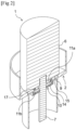
- the pump comprises a pump body 2, in which the various constituent elements of the pump described below are housed.
- the pump 1 is semi-submerged, which for the purposes of the present invention means that it is partly below the level 3 of the water in the pool, and partly above the level 3. More precisely, the pump 1 comprises a hydraulic part 4, partially submerged, and of which certain non-submerged elements can be exposed to the water in the pool for example by splashing, and a motor part 5, located above the hydraulic part 4, and of which the elements are, in normal operation, protected from the water.
- Pump 1 has a motor 6, for example an asynchronous, single-phase electric motor, powered by alternating current, with a power of the order of 200 to 1000W.
- the motor is located in the motor part 5, and is therefore above level 3, and protected from water.
- the pump 1 also comprises a shaft 7 with a vertical axis, extending below the motor 6 and configured to be driven in rotation by the motor 6.
- the shaft 7 is preferably of circular section. The lower end of the shaft 7 is located below the level 3.
- the pump 1 also comprises a wall 9 transverse to the axis of the shaft 7.
- the axis of the shaft 7 being vertical, the term "transverse” here means that the wall 9 is not vertical.
- the wall 9 is preferably horizontal, but it may have an angle with the horizontal, without departing from the scope of the invention.
- the wall 9 is integral with the pump body 2.
- the wall 9 belongs for example to the body of the motor 6, which encloses the constituent elements of the motor 6.
- the wall 9 corresponds to the lower wall of the body of the motor 6.
- integral applied to two parts means that these two parts are fixed relative to each other, without relative movement, under normal conditions of use of the pump.
- the wall 9 is crossed by the shaft 7.
- the wall 9 therefore has an opening, through which the shaft 7 passes.
- This opening is preferably circular, which makes it possible to reduce the space between the edges of the opening and the shaft 7, a seal being able to be located at the edges of the opening in order to protect the motor 6 from water.
- the pump 1 comprises, according to the invention, a sealing device 10 for preventing water and any salt crystals from accessing the upper part of the lower hydraulic part.
- the sealing device 10 is located under the motor and extends around a section of the shaft 7, so as to form a sealed chamber 11.
- the elements which are likely to be reached by splashes of water and located at the top of the hydraulic part 4 and at the bottom of the motor part 5 of the pump 1 are protected from this water. This is particularly useful when the water is slightly salty, salt being corrosive for some of these elements.
- the salt crystals progressing by capillarity with the successive splashes, exert a mechanical and chemical pressure on these elements which increases the corrosive effect of the salt.
- the sealing device 10 comprises a lower outer opening 12, preferably circular in shape, through which the shaft 7 passes.
- the inner edges of the lower outer opening 12 are in sealing contact with the shaft 7, so that water cannot rise between the shaft 7 and the edges of the lower outer opening 12.
- the sealing device 10 also comprises an upper outer opening 13, the inner edges of which are in sealing contact with the wall 9, so that water cannot pass between the wall 9 and the upper outer opening 13.
- the upper outer opening 13 is preferably circular in shape, but it can take other shapes to adapt to the geometry of the wall 9.
- the upper external opening 13 has, for example, a dimension greater than or equal to three times the surface area of the section of the shaft 7 taken at the level of the upper external opening 13, in order to properly include in the chamber 11 the elements located around the upper part of the shaft 7 which must be protected from the water in the basin.
- the height of the sealing device 10, defined as being the length of the section of the section of the shaft 7 between the wall 9 and the lower external opening 12, is for example greater than or equal to one third of the average diameter of the section of the shaft 7 measured at the level of the sealing device.
- the lower 12 and upper 13 external openings are named as such because they open onto the exterior of the sealing device 10.
- the sealing device 10 preferably comprises a deflector 14.
- the deflector 14 may be made of any material usually used for sealing gaskets, for example an elastomer such as a fluoropolymer.
- the following materials may, for example, be suitable: a fluorocarbon (FKM), a hydrogenated butadiene-acrylonitrile copolymer (HNBR), or a butadiene-acrylonitrile copolymer (HBR).
- FKM fluorocarbon
- HNBR hydrogenated butadiene-acrylonitrile copolymer
- HBR butadiene-acrylonitrile copolymer
- the Shore hardness of the elastomer is preferably between 60 and 80, for example 70.
- the deflector 14 comprises the lower external opening 12 and the upper external opening 13.
- the sealed chamber can be formed in a conventional semi-submersible pump, by the addition of a single part.
- the sealed chamber can then be delimited by the wall 9, the deflector, and the section of the shaft located at the level between the upper 13 and lower 12 external openings.
- the pump 1 has a partition 15 transverse to the axis of the shaft 7.
- the axis of the shaft 7 being vertical, we mean here by the term "transverse" that the partition 15 is not vertical.
- the partition 15 is preferably horizontal, but it can have an angle with the horizontal, without departing from the scope of the invention.
- the partition 15 is integral with the pump body 2.
- the partition 15 belongs for example to the body of the pump, also called lantern, which envelops all of the constituent elements of the pump.
- the partition 15 is crossed by the shaft 7.
- the partition 15 therefore has an opening, through which the shaft 7 passes.
- This opening is preferably circular, which makes it possible to reduce the space between the edges of the opening and the shaft 7, a seal being able to be located at the edges of the opening in order to protect the motor 6 from water.
- this seal is not necessarily useful in the context of the invention, since the opening of the partition 15 through which the shaft 7 passes is located in the chamber 11.
- the partition 15 has at least one hole 16 located outside the chamber, so that water can flow down from the motor part 5 to the hydraulic part 4. This is required in particular by electrical safety standards.
- partition 15 divides room 11 into two sub-rooms 11a, 11b.
- a first sub-chamber 11a is located between the wall 9 and the partition 15, in particular under the wall 9 and above the partition 15.
- the first sub-chamber 11a is further delimited by a section of the shaft 7 and a chamber seal 17.
- the chamber seal 17 comprises the upper external opening 13, and a lower internal opening 18 whose edges are in sealed contact with the partition 15, in particular with the upper face of the partition 15. In other words, the chamber seal 17 is interposed in sealed contact between the wall 9 and the partition 15.
- the chamber seal 17 is therefore preferably integral with these two surfaces, i.e. with the pump body 2, in order to provide a static seal.
- the chamber seal 17 is preferably an O-ring, which has the advantage of being a standard seal whose dimensions will be chosen according to the spacing between the wall 9 and the partition 15. Most known O-rings may be suitable, whether they are of flat, circular, quadrilobe section, etc. It may also be a non-O-ring seal without departing from the scope of the invention.
- the chamber seal 17 may be made of any material usually used for sealing seals, for example an elastomer such as a fluoropolymer. The following materials may, for example, be suitable: a fluorocarbon (FKM), a hydrogenated butadiene-acrylonitrile copolymer (HNBR), or a butadiene-acrylonitrile copolymer (NBR).
- FKM fluorocarbon
- HNBR hydrogenated butadiene-acrylonitrile copolymer
- NBR butadiene-acrylonitrile copolymer
- the Shore hardness of the elastomer is preferably between 60 and
- a second sub-chamber 11b is located under the partition 15.
- the second sub-chamber 11b is further delimited by a section of the shaft and the deflector 14.
- the deflector 14 comprises the lower external opening 12, and an upper internal opening 19 whose edges are in sealed contact with the partition 15, in particular with the lower face of the partition 15.
- the two sub-chambers 11a, 11b communicate at least through the opening of the partition 15 through which the shaft 7 passes, unless a seal is located between the edges of this opening and the shaft.
- the deflector 14 is in sealed contact with the wall 9, in the first embodiment, or the partition 15, in the second embodiment illustrated in Fig. 1 , and the shaft 7, by the edges of its lower external opening 12. Now the shaft 7 is in movement relative to the motor 6, and therefore it is in movement relative to the wall 9 and possibly the partition 15 which are integral with the motor 6.
- the deflector 14 is integral with the shaft 7.
- the seal between the edges of the lower outer opening 12 and the shaft 7 is therefore a static seal
- the seal between the upper outer opening 13 and the wall 9, in the first embodiment, or the upper inner opening 19 and the partition 15, in the second embodiment is a dynamic seal.
- the upper outer opening 13 or upper inner opening 19 of the deflector 14 may comprise a flexible lip whose end is capable of matching the shape of the wall 9 or the partition 15, by exerting pressure on the wall 9 or the partition 15.
- the deflector 14 is integral with the pump body 2.
- the seal between the edges of the lower external opening 12 and the shaft 7 is therefore a dynamic seal
- the seal between the upper external opening 13 and the wall 9, in the first embodiment, or the upper internal opening 19 and the partition 15, in the second embodiment is a static seal.
- the lower external opening 12 of the deflector 14 may comprise a flexible lip whose end is capable of matching the shape of the shaft 7, by exerting pressure on the shaft 7.
- the flexible lip may be made in one piece with the rest of the deflector 14, or be manufactured separately and then fixed to the rest of the deflector 14. In this case, it is possible to use a different material for the lip, for example a more flexible material than the rest of the deflector 14.
- the sealing device and in particular the deflector and/or the chamber seal, are preferably removable, so that they can be easily cleaned or replaced if necessary.
- the sealing device 10 makes it possible to provide a waterproof barrier to prevent access to water and possibly salt crystals to the upper motor part of the pump, and to the top of the lower hydraulic part.
- this sealing is not always sufficient.
- the deflectors and/or seals used do not necessarily provide perfect sealing, particularly in places where the sealing is dynamic.
- the chamber 11 is filled with a product constituting an additional sealing barrier.
- This product is, for example, a hydrophobic grease.
- the hydrophobic nature has the advantage that the product tends to remain in the chamber 11, the exterior being a humid environment.
- the greases may have kinematic viscosity levels that may be suitable for the present invention, for example, between 250 and 300 mm 2 /s at 25°C.
- the pump 1 may comprise one or more annular elements 20.
- the annular elements 20 may extend around the shaft 7, directly under the partition 15, in the vicinity of the contact between the deflector 14 and the partition 15.
- the annular elements 20 are for example placed less than 3 mm from this contact zone, preferably at a distance equal to or less than 1 mm.
- the annular elements 20 preferably have at least one flat face parallel to the axis of the shaft 7, with a dimension for example between 2 and 3 mm along the axis of the shaft 7. To do this, and as illustrated in the Fig. 1 , the section of the annular elements 20 is preferably rectangular.
- the pump may comprise a single annular element 20, preferably arranged outside the sealed chamber 11, i.e. outside the perimeter of the deflector 14.
- the pump comprises two annular elements 20, one arranged outside the sealed chamber 11, and the other arranged inside the sealed chamber 11.
- annular elements 20 are particularly relevant when the deflector 14 is integral with the shaft 7, and the seal between the partition 15 and the deflector 14 is a dynamic seal.
- the present invention also relates to a water filtration unit for a pool, in particular a swimming pool, comprising a pump 1 according to the invention, and an electrolysis cell for treating the water with salt.
- a pump 1 comprising a sealing device 10 is especially advantageous when the water in the pool is salty, and when, upon evaporation, the salt crystals attack the elements of the pump 1 located near and above the water level 3.
Landscapes
- Engineering & Computer Science (AREA)
- Mechanical Engineering (AREA)
- General Engineering & Computer Science (AREA)
- Structures Of Non-Positive Displacement Pumps (AREA)
Claims (12)
- Vertikale halbtauchende Pumpe (1) für eine Wasserfiltergruppe eines Beckens, insbesondere eines Schwimmbeckens, die ein Pumpengehäuse (2) aufweist, in dem ein Motor (6) untergebracht ist, der so angeordnet ist, dass er sich über dem Wasserspiegel (3) des Beckens befindet, wobei sich eine Welle (7) mit vertikaler Achse vom Motor (6) und unter diesem erstreckt, das untere Ende der Welle (7) mit vertikaler Achse so angeordnet ist, dass es sich unter dem Wasserspiegel (3) des Beckens befindet, die Welle (7) so angeordnet ist, dass sie von dem Motor (7) in Drehung versetzt wird, die Welle (7) durch eine Wand (9) und eine Trennwand (15), die sich unter dem Motor (6) befinden und fest mit dem Pumpengehäuse (2) verbunden sind, durchgeführt, wobei die Trennwand (15) sich unter der Wand (9) befindet,dadurch gekennzeichnet, dass die Pumpe (1) außerdem eine Dichtungsvorrichtung (19) aufweist, wobei die Dichtungsvorrichtung (10) Folgendes umfasst:- eine Ablenkeinrichtung (14) mit einer Außenöffnung (12) auf der Unterseite, durch welche die Welle (7) führt und deren innere Ränder einen dichten Kontakt mit der Welle (7) herstellen, und einer Innenöffnung (19) auf der Oberseite, durch welche die Welle (7) führt und deren Ränder einen dichten Kontakt mit der Trennwand (15) herstellen, und- eine Kammerdichtung (17) mit einer Außenöffnung (13) auf der Oberseite, deren Ränder einen dichten Kontakt zur Wand (9) herstellen, und eine Innenöffnung (18) auf der Unterseite, durch welche die Welle (7) führt und deren Ränder eine dichten Kontakt zur Trennwand (15) herstellen,wobei die Dichtungsvorrichtung (10) so angeordnet ist, dass sie eine dichte Kammer (11) bildet, die sich unter dem Motor (6) und um einen Abschnitt der Welle (7) herum erstreckt, und die Kammer (11) durch die Trennwand (15) in zwei Unterkammern (11a, 11b) unterteilt ist.
- Pumpe (1) nach Anspruch 1, die dadurch gekennzeichnet ist, dass die Ablenkeinrichtung (14) und/oder die Kammerdichtung (17) aus einem Elastomer, wie z. B. einem Fluorpolymer, hergestellt sind.
- Pumpe nach einem der Ansprüche 1 bis 2, die dadurch gekennzeichnet ist, dass die Ablenkeinrichtung (14) fest mit der Welle (7) verbunden ist.
- Pumpe nach einem der Ansprüche 1 bis 2, die dadurch gekennzeichnet ist, dass die Ablenkeinrichtung (14) fest mit dem Pumpengehäuse (2) verbunden ist.
- Pumpe nach einem der Ansprüche 1 bis 4, die dadurch gekennzeichnet ist, dass die Kammerdichtung (17) fest mit dem Pumpengehäuse (2) verbunden ist.
- Pumpe nach einem der Ansprüche 1 bis 5, die dadurch gekennzeichnet ist, dass die dichte Kammer (11) zumindest teilweise mit einem hydrophoben Fett gefüllt ist.
- Pumpe nach Anspruch 6, dadurch gekennzeichnet, dass das hydrophobe Fett eine kinematische Viskosität zwischen 250 und 300 mm2/s bei einer Temperatur von 25°C aufweist.
- Pumpe nach einem der Ansprüche 1 bis 7, die mindestens ein ringförmiges Element (20) aufweist, das um die Welle (7) herum unter der Trennwand (15) und gegen diese angeordnet ist, wobei der Abstand zwischen dem ringförmigen Element (20) und dem Kontaktbereich zwischen der Ablenkvorrichtung (14) und der Trennwand (15) unter 3 mm liegt.
- Pumpe nach Anspruch 8, bei der mindestens ein ringförmiges Element (2) außerhalb der dichten Kammer (11) angeordnet ist.
- Pumpe nach Anspruch 8, die mindestens zwei ringförmige Elemente (20) aufweist, wobei mindestens eines der ringförmigen Elemente (20) in der dichten Kammer (11) und mindestens eines der ringförmigen Elemente (20) außerhalb der dichten Kammer (11) angeordnet ist.
- Filtergruppe für Wasser eines Beckens, insbesondere eines Schwimmbeckens, mit einer vertikalen, halbtauchenden Pumpe nach einem der Ansprüche 1 bis 10 und einer Elektrolysezelle für eine Wasserbehandlung mit Salz.
- Becken, insbesondere ein Schwimmbad, das eine Filtergruppe nach Anspruch 11 umfasst, wobei das Wasser des Beckens zwischen 0,5 und 6 Gramm Liter Salz enthält.
Applications Claiming Priority (1)
| Application Number | Priority Date | Filing Date | Title |
|---|---|---|---|
| FR2303400A FR3147599A1 (fr) | 2023-04-05 | 2023-04-05 | Pompe verticale semi-immergee |
Publications (3)
| Publication Number | Publication Date |
|---|---|
| EP4443006A1 EP4443006A1 (de) | 2024-10-09 |
| EP4443006C0 EP4443006C0 (de) | 2025-06-04 |
| EP4443006B1 true EP4443006B1 (de) | 2025-06-04 |
Family
ID=86851364
Family Applications (1)
| Application Number | Title | Priority Date | Filing Date |
|---|---|---|---|
| EP23216978.9A Active EP4443006B1 (de) | 2023-04-05 | 2023-12-15 | Vertikale halbtauchpumpe |
Country Status (3)
| Country | Link |
|---|---|
| EP (1) | EP4443006B1 (de) |
| ES (1) | ES3031962T3 (de) |
| FR (1) | FR3147599A1 (de) |
Family Cites Families (2)
| Publication number | Priority date | Publication date | Assignee | Title |
|---|---|---|---|---|
| US10527052B2 (en) * | 2014-07-10 | 2020-01-07 | Dab Pumps S.P.A. | Centrifugal pump of the submersed or submersible type |
| CN114876857B (zh) * | 2022-04-20 | 2025-02-11 | 台州义民电机股份有限公司 | 新式机封布置结构及采用该结构的潜水泵 |
-
2023
- 2023-04-05 FR FR2303400A patent/FR3147599A1/fr active Pending
- 2023-12-15 EP EP23216978.9A patent/EP4443006B1/de active Active
- 2023-12-15 ES ES23216978T patent/ES3031962T3/es active Active
Also Published As
| Publication number | Publication date |
|---|---|
| EP4443006A1 (de) | 2024-10-09 |
| EP4443006C0 (de) | 2025-06-04 |
| FR3147599A1 (fr) | 2024-10-11 |
| ES3031962T3 (en) | 2025-07-14 |
Similar Documents
| Publication | Publication Date | Title |
|---|---|---|
| CH679173A5 (de) | ||
| FR3042808B1 (fr) | Appareil nettoyeur de piscine a dispositif de franchissement d'obstacle | |
| FR2517372A1 (fr) | Dispositif pour le degazage des pompes d'alimentation en carburant | |
| EP2402613B1 (de) | Trockenvakuumpumpe | |
| FR2524414A1 (fr) | Dispositif de propulsion marine a anode soluble associee au coussinet de butee | |
| FR2704617A1 (fr) | Garniture d'étanchéité pour arbre tournant. | |
| EP4443006B1 (de) | Vertikale halbtauchpumpe | |
| WO2013001015A1 (fr) | Engin sous-marin de nettoyage de surfaces immergees | |
| FR2534654A1 (fr) | Dispositif d'etancheite comportant au moins une levre coulissante | |
| EP0063062B1 (de) | Dichtung für Kreiselmaschine mit hydraulischer Flüssigkeit | |
| EP2986821B1 (de) | Drehflügelvakuumpumpe | |
| EP3414475B1 (de) | Verbesserte dichtungsvorrichtung, insbesondere im hinblick auf eine kontamination durch externe agenten | |
| EP0369878B1 (de) | Lagerkammer mit einem Ölleitschirm | |
| FR2927395A3 (fr) | Bague de protection d'un joint d'etancheite dynamique entre une piece fixe et un arbre de transmission d'un groupe motopropulseur d'un vehicule automobile et groupe motopropulseur comportant une telle bague de protection | |
| FR3038239A1 (fr) | Coalesceur rotatif | |
| EP4522889A1 (de) | Ölverteilungswanne für ein getriebe | |
| FR2492904A2 (fr) | Perfectionnements aux pompes et moteurs a fluide a engrenages | |
| FR2558539A1 (fr) | Pompe centrifuge a etages multiples perfectionnee du type a couronne mobile fermee | |
| FR2766242A1 (fr) | Pompe a engrenages | |
| EP0421900A1 (de) | Dichtungseinrichtung für ein zylindrisch hin- und hergehendes oder drehendes Teil in einem Raum | |
| FR3043149A1 (fr) | Systeme d'etancheite ameliore pour arbre tournant | |
| FR2697598A1 (fr) | Dispositif de protection contre l'entrée de particules et de polluants solides. | |
| EP0578533A1 (de) | Flügelzellenpumpe für Lebensmittel | |
| FR3012925A1 (fr) | Moteur pour pompe ou broyeur sanitaire, du type rotor-stator immerge dans de l'huile dans une carcasse etanche | |
| FR3136261A1 (fr) | Pompe à vide verticale |
Legal Events
| Date | Code | Title | Description |
|---|---|---|---|
| PUAI | Public reference made under article 153(3) epc to a published international application that has entered the european phase |
Free format text: ORIGINAL CODE: 0009012 |
|
| STAA | Information on the status of an ep patent application or granted ep patent |
Free format text: STATUS: THE APPLICATION HAS BEEN PUBLISHED |
|
| AK | Designated contracting states |
Kind code of ref document: A1 Designated state(s): AL AT BE BG CH CY CZ DE DK EE ES FI FR GB GR HR HU IE IS IT LI LT LU LV MC ME MK MT NL NO PL PT RO RS SE SI SK SM TR |
|
| STAA | Information on the status of an ep patent application or granted ep patent |
Free format text: STATUS: REQUEST FOR EXAMINATION WAS MADE |
|
| 17P | Request for examination filed |
Effective date: 20241029 |
|
| RBV | Designated contracting states (corrected) |
Designated state(s): AL AT BE BG CH CY CZ DE DK EE ES FI FR GB GR HR HU IE IS IT LI LT LU LV MC ME MK MT NL NO PL PT RO RS SE SI SK SM TR |
|
| GRAP | Despatch of communication of intention to grant a patent |
Free format text: ORIGINAL CODE: EPIDOSNIGR1 |
|
| STAA | Information on the status of an ep patent application or granted ep patent |
Free format text: STATUS: GRANT OF PATENT IS INTENDED |
|
| GRAS | Grant fee paid |
Free format text: ORIGINAL CODE: EPIDOSNIGR3 |
|
| GRAA | (expected) grant |
Free format text: ORIGINAL CODE: 0009210 |
|
| STAA | Information on the status of an ep patent application or granted ep patent |
Free format text: STATUS: THE PATENT HAS BEEN GRANTED |
|
| INTG | Intention to grant announced |
Effective date: 20250403 |
|
| AK | Designated contracting states |
Kind code of ref document: B1 Designated state(s): AL AT BE BG CH CY CZ DE DK EE ES FI FR GB GR HR HU IE IS IT LI LT LU LV MC ME MK MT NL NO PL PT RO RS SE SI SK SM TR |
|
| REG | Reference to a national code |
Ref country code: GB Ref legal event code: FG4D Free format text: NOT ENGLISH |
|
| REG | Reference to a national code |
Ref country code: CH Ref legal event code: EP |
|
| REG | Reference to a national code |
Ref country code: IE Ref legal event code: FG4D Free format text: LANGUAGE OF EP DOCUMENT: FRENCH |
|
| U01 | Request for unitary effect filed |
Effective date: 20250604 |
|
| U07 | Unitary effect registered |
Designated state(s): AT BE BG DE DK EE FI FR IT LT LU LV MT NL PT RO SE SI Effective date: 20250611 |
|
| REG | Reference to a national code |
Ref country code: ES Ref legal event code: FG2A Ref document number: 3031962 Country of ref document: ES Kind code of ref document: T3 Effective date: 20250714 |
|
| PG25 | Lapsed in a contracting state [announced via postgrant information from national office to epo] |
Ref country code: GR Free format text: LAPSE BECAUSE OF FAILURE TO SUBMIT A TRANSLATION OF THE DESCRIPTION OR TO PAY THE FEE WITHIN THE PRESCRIBED TIME-LIMIT Effective date: 20250905 Ref country code: NO Free format text: LAPSE BECAUSE OF FAILURE TO SUBMIT A TRANSLATION OF THE DESCRIPTION OR TO PAY THE FEE WITHIN THE PRESCRIBED TIME-LIMIT Effective date: 20250904 |
|
| PG25 | Lapsed in a contracting state [announced via postgrant information from national office to epo] |
Ref country code: PL Free format text: LAPSE BECAUSE OF FAILURE TO SUBMIT A TRANSLATION OF THE DESCRIPTION OR TO PAY THE FEE WITHIN THE PRESCRIBED TIME-LIMIT Effective date: 20250604 |
|
| PG25 | Lapsed in a contracting state [announced via postgrant information from national office to epo] |
Ref country code: HR Free format text: LAPSE BECAUSE OF FAILURE TO SUBMIT A TRANSLATION OF THE DESCRIPTION OR TO PAY THE FEE WITHIN THE PRESCRIBED TIME-LIMIT Effective date: 20250604 |
|
| PG25 | Lapsed in a contracting state [announced via postgrant information from national office to epo] |
Ref country code: RS Free format text: LAPSE BECAUSE OF FAILURE TO SUBMIT A TRANSLATION OF THE DESCRIPTION OR TO PAY THE FEE WITHIN THE PRESCRIBED TIME-LIMIT Effective date: 20250904 |