EP4442938A1 - Cylinder lock and door - Google Patents
Cylinder lock and door Download PDFInfo
- Publication number
- EP4442938A1 EP4442938A1 EP22901220.8A EP22901220A EP4442938A1 EP 4442938 A1 EP4442938 A1 EP 4442938A1 EP 22901220 A EP22901220 A EP 22901220A EP 4442938 A1 EP4442938 A1 EP 4442938A1
- Authority
- EP
- European Patent Office
- Prior art keywords
- cylinder
- driver pin
- outer cylinder
- inner cylinder
- diameter
- Prior art date
- Legal status (The legal status is an assumption and is not a legal conclusion. Google has not performed a legal analysis and makes no representation as to the accuracy of the status listed.)
- Pending
Links
Images




Classifications
-
- E—FIXED CONSTRUCTIONS
- E05—LOCKS; KEYS; WINDOW OR DOOR FITTINGS; SAFES
- E05B—LOCKS; ACCESSORIES THEREFOR; HANDCUFFS
- E05B27/00—Cylinder locks or other locks with tumbler pins or balls that are set by pushing the key in
- E05B27/0003—Details
- E05B27/0017—Tumblers or pins
-
- E—FIXED CONSTRUCTIONS
- E05—LOCKS; KEYS; WINDOW OR DOOR FITTINGS; SAFES
- E05B—LOCKS; ACCESSORIES THEREFOR; HANDCUFFS
- E05B19/00—Keys; Accessories therefor
- E05B19/0017—Key profiles
- E05B19/0041—Key profiles characterized by the cross-section of the key blade in a plane perpendicular to the longitudinal axis of the key
- E05B19/0047—Key profiles characterized by the cross-section of the key blade in a plane perpendicular to the longitudinal axis of the key with substantially circular or star-shape cross-section
-
- E—FIXED CONSTRUCTIONS
- E05—LOCKS; KEYS; WINDOW OR DOOR FITTINGS; SAFES
- E05B—LOCKS; ACCESSORIES THEREFOR; HANDCUFFS
- E05B27/00—Cylinder locks or other locks with tumbler pins or balls that are set by pushing the key in
- E05B27/0003—Details
- E05B2027/0025—Details having means preventing rotation of the tumbler
-
- E—FIXED CONSTRUCTIONS
- E05—LOCKS; KEYS; WINDOW OR DOOR FITTINGS; SAFES
- E05B—LOCKS; ACCESSORIES THEREFOR; HANDCUFFS
- E05B63/00—Locks or fastenings with special structural characteristics
- E05B63/0004—Additional locks added to existing lock arrangements
Definitions
- the present disclosure relates to cylinder locks and doors.
- a cylinder lock installed in residential doors and similar applications are known.
- a cylinder lock includes an outer cylinder, an inner cylinder rotatably engaging with the outer cylinder, a driver pin that restricts the rotation of the inner cylinder, and a tumbler pin.
- the unlocking key corresponding to the cylinder lock includes protrusions and indentations formed in portions contacting the tumbler pin.
- Patent Document 1 Japanese Unexamined Patent Application, Publication No. H9-170363
- the total length of the driver pin In order to downsize the cylinder lock for space-saving and cost reduction purposes, the total length of the driver pin needs to be shortened. Meanwhile, a certain clearance is provided between the driver pin and the pinhole of the outer cylinder that accommodates the driver pin. Therefore, simply shortening the total length of the driver pin may cause the driver pin to topple over inside the pinhole.
- One approach to avoiding this situation may be to narrow the clearance between the driver pin and the pinhole.
- the driver pin could not be inserted into the pinhole of the inner cylinder due to misalignment between the pinhole of the outer cylinder and the pinhole of the inner cylinder. Since the inner cylinder is rotatably fixed to the outer cylinder, it is impossible to completely eliminate the misalignment between the pinhole of the outer cylinder and the pinhole of the inner cylinder.
- the present disclosure has been made in light of the above, and aims to provide a cylinder lock that can prevent the driver pin from toppling over inside the pinhole, even when the driver pin is shortened.
- the present disclosure relates to a cylinder lock including an outer cylinder and an inner cylinder that rotatably engages with the outer cylinder, in which holes are formed in the outer and inner cylinders, the holes communicate with the keyhole, the driver pin can be inserted into the holes, and the diameter of the driver pin on the outer cylinder side is larger than the diameter of the driver pin on the inner cylinder side.
- a cylinder lock 10 is used in conjunction with an unlocking key 5 capable of locking and unlocking the cylinder lock 10 in a locking device 1.
- the cylinder lock 10 includes an inner cylinder 2, an outer cylinder 3, a decorative member 4, a driver pin 61, and a tumbler pin 62.
- the inner cylinder 2 rotatably engages with the fixed outer cylinder 3.
- the inner cylinder 2 is a substantially cylindrical member that rotatably engages with the outer cylinder 3.
- the material for the inner cylinder 2 is not particularly limited, and may be composed of metal such as brass, for example.
- An outer peripheral surface 20 being the sliding surface of the inner cylinder 2 contacts an inner peripheral surface 30 of the outer cylinder 3, and engages with the outer cylinder 3.
- a keyhole 21, into which the unlocking key 5 can be inserted, is formed in the inner cylinder 2 along the axial direction of the inner cylinder 2.
- a plurality of pinholes 22 communicating with the keyhole 21 are formed in the outer peripheral surface 20 of the inner cylinder 2. At least part of the driver pin 61 and the tumbler pin 62 can be inserted into and removed from the plurality of pinholes 22.
- Each of the pinholes 22 has a cylindrical inner peripheral surface 22a.
- a plurality of rows of pinholes 22 are formed along the axial direction of the inner cylinder 2, and a plurality of pairs of pinholes 22 are formed in the circumferential direction of the inner cylinder 2.
- a flange 23 is provided on the end face of the inner cylinder 2, on the side of inserting the unlocking key 5.
- the flange 23 may be formed integrally with the inner cylinder 2 or may be a component separate from the inner cylinder 2.
- a groove 24, with which a pair of fixing pins 7 can engage, is provided near the end face of the inner cylinder 2, opposite to the side of inserting the unlocking key 5.
- the groove 24 is provided along the circumferential direction of the inner cylinder 2.
- an indentation having a length L1 in a side view is formed between the flange 23 and the fixing pins 7 engaging with the groove 24.
- Part of the outer cylinder 3 engages with indentation, whereby the inner cylinder 2 rotatably engages with the outer cylinder 3. The state of engagement between the inner cylinder 2 and the outer cylinder 3 will be described later in detail.
- the outer cylinder 3 is a substantially cylindrical member, in which the inner cylinder 2 can engage with holes 31 formed inside the outer cylinder 3.
- the material for the outer cylinder 3 is not particularly limited, and may be composed of metal such as brass, for example, as in the case of the inner cylinder 2.
- the outer cylinder 3 is fixed and non-rotatable.
- the inner peripheral surface 30 being the sliding surface of the outer cylinder 3 contacts the outer peripheral surface 20 of the inner cylinder 2, and engages with the inner cylinder 2.
- the holes 31, with which the inner cylinder 2 can engage, are formed in the outer cylinder 3 along the axial direction of the outer cylinder 3.
- a plurality of pinholes 32 communicating with the holes 31 are formed in the outer peripheral surface of the outer cylinder 3. At least part of the driver pin 61 and the tumbler pin 62 can be inserted into and removed from the plurality of pinholes 32.
- Each of the plurality of pinholes 32 has a cylindrical inner peripheral surface 32a.
- the plurality of pinholes 22 and 32 communicate with each other such that at least part of the driver pin 61 and the tumbler pin 62 are insertable and removable when the inner cylinder 2 rotates to a predetermined position relative to the outer cylinder 3.
- a pair of holes 33 through which a pair of fixing pins 7 can be inserted, respectively, are formed in the outer peripheral surface of the outer cylinder 3.
- the holes 33 communicate with the holes 31, as in the case of the pinholes 32.
- the holes 33 are provided near the end face opposite to the end face 31a of the outer cylinder 3, as illustrated in Fig. 5 .
- the length L2 between the end face 31a and the edge of the fixing pins 7 is slightly smaller than the length L1 of the indentation, providing a clearance only by the difference between L1 and L2. Therefore, when the inner cylinder 2 engages with the outer cylinder 3, and the unlocking key 5 is inserted into and removed from the keyhole 21, the clearance may cause misalignment between the pinholes 22 and 32.
- the decorative member 4 covers and decorates the front face of the cylinder lock 10, which is the face on the keyhole 21 side of the inner cylinder 2 and the outer cylinder 3.
- the decorative member 4 includes a hole communicating with the keyhole 21.
- the material for the decorative member 4 is not particularly limited, and may be composed of metal or the like.
- a plated layer or the like for enhancing the design may be formed on the surface of the decorative member 4.
- the decorative member 4 makes the inner cylinder 2 and the outer cylinder 3 almost invisible from the outside. Instead of the decorative member 4, at least the front part of the inner cylinder 2 and the outer cylinder 3 may be decorated, for example, with a plated layer.
- the driver pins 61 and the tumbler pins 62 are members that have a substantially circular columnar shape and are slidably accommodated in the pin holes 22 and 32.
- the tumbler pin 62 is arranged on the keyhole 21 side, has a rounded tip 62b that contacts the unlocking key 5, and has an enlarged-diameter part 62a at the edge that contacts the driver pin 61, as illustrated in Fig. 6 .
- the driver pin 61 has an edge that contacts the tumbler pin 62, and another edge that contacts an urging member (not illustrated).
- driver pins 61 and tumbler pins 62 illustrates only one pair of driver pins 61 and one pair of tumbler pins 62 for simplicity, there are a plurality of pairs of driver pins 61 and tumbler pins 62, which are accommodated in the plurality of pairs of pinholes 22 and 32.
- driver pins 61 and tumbler pins 62 are arranged in the axial direction of the circular keyhole 21.
- the rows of the driver pins 61 and tumbler pins 62 arranged in the axial direction of the keyhole 21 are not limited to six rows, and can be any number of rows such as three or more rows, for example.
- the inner cylinder 2 can rotate in synchrony with the unlocking key 5.
- the top of the tapered part 61b1 and the top of the tapered part 62a1 are partially flat.
- An urging member urges the driver pin 61 towards the keyhole 21.
- the driver pin 61 is positioned between the inner cylinder 2 and the outer cylinder 3, thus restricting the rotation of the inner cylinder 2.
- the lengths of the driver pin 61 and the tumbler pin 62 are set, and the indentations and protrusions formed on the surface of the unlocking key 5 are set, such that the contact surfaces of the driver pin 61 and the tumbler pin 62 coincide with the shear line SL being the contact surfaces of the inner cylinder 2 and the outer cylinder 3.
- the inner cylinder 2 rotates in synchrony with the unlocking key 5.
- the deadbolt of the door can be pulled out or retracted, thereby enabling the locking and unlocking of the cylinder lock 10.
- the diameter L41 of the driver pin 61 near the outer cylinder 3 is larger than the diameter L5 of the driver pin 61 near the inner cylinder 2. Since the clearance between the diameter L41 and the diameter L3 of the pinhole 32 is reduced from the conventional cases, the driver pin 61 can be prevented from toppling over inside the pinhole 32, even when the total length of the driver pin 61 is shortened.
- a case is described in which the diameter of the driver pin 61 is maintained constant, and the clearance between the diameter L41 and the diameter L3 of the pinhole 32 is reduced from the conventional cases.
- the driver pin 61 can be prevented from toppling over inside the pinhole 32, the driver pin 61 accommodated in the pinhole 32 may not be insertable into the pinhole 22 due to misalignment between the pinholes 22 and 32.
- the driver pin 61 since the diameter L5 of the driver pin 61 near the inner cylinder 2 is smaller than the diameter L41 of the driver pin 61 near the outer cylinder 3, the driver pin 61 can be inserted into the pinhole 22, while achieving the effect of preventing the toppling.
- the driver pin 61 includes a posture maintaining region 61a and a communication region 61b.
- the posture maintaining region 61a is arranged on the outer cylinder 3 side, and the communication region 61b is arranged on the inner cylinder 2 side.
- the posture maintaining region 61a preferably has a substantially rectangular shape in a side view, and has a constant diameter L41 over a certain length L42 in the axial direction from the edge of the driver pin 61 on the outer cylinder 3 side. That is, a step 61c is preferably provided between the posture maintaining region 61a and the communication region 61b. As a result, the driver pin 61 can be effectively prevented from toppling over inside the pinhole 32.
- the posture maintaining region 61a may have a tapered shape, in which the driver pin 61 has the largest diameter at the edge of on the outer cylinder 3 side and gradually decreases in diameter towards the inner cylinder 2 side.
- the ratio of the axial length L42 to the diameter L41 which is the axial length/diameter ratio of the posture maintaining region 61a, is preferably 0.3 or more.
- the driver pin 61 can be prevented from toppling over inside the pinhole 32, and the total length of the driver pin 61 can be shortened.
- the axial length/diameter ratio is preferably 0.5 or more.
- the communication region 61b has a constant diameter L5 over a certain length in the axial direction from the edge of the driver pin 61 on the inner cylinder 2 side.
- the diameter L5 of the communication region 61b is smaller than the diameter L41 of the posture maintaining region 61a.
- the difference between the diameter L41 of the posture maintaining region 61a and the diameter L5 of the communication region 61b is preferably at least as large as the difference between L1 and L2, corresponding to the clearance between the inner cylinder 2 and the outer cylinder 3.
- This clearance corresponds to the maximum value of misalignment between the pinholes 22 and 32. Therefore, by setting the difference between L5 and L41 at least as large as this clearance, the communication region 61b can be inserted into the pinhole 22, even when misalignment arises between the pinholes 22 and 32.
- the posture maintaining region 61a and the communication region 61b may be formed as separate components, but are preferably formed integrally from the perspective of ensuring machining accuracy.
- the unlocking key 5 can lock and unlock the cylinder lock 10.
- the insertion part of the unlocking key 5 into the keyhole 21 has a circular columnar shape.
- Fig. 1 illustrates the unlocking key 5 as a blank key.
- a door 100 As illustrated in Fig. 7 , a door 100 according to the present embodiment is installed so as to be openable and closable, in a door opening A of a building structure.
- the door 100 On the door front side, the door 100 includes a handle 9 for opening and closing the door 100, and a pair of cylinder locks 10 arranged above and below the handle 9.
- the door 100 is used, for example, as a front door.
- the communication region 61b has the constant diameter L5 over a certain length in the axial direction from the edge of the driver pin 61 on the inner cylinder 2 side.
- the communication region 61b may have varying diameters in the axial direction, by having a tapered shape, for example.
Landscapes
- Lock And Its Accessories (AREA)
Abstract
Description
- The present disclosure relates to cylinder locks and doors.
- Conventionally, cylinder locks installed in residential doors and similar applications are known. A cylinder lock includes an outer cylinder, an inner cylinder rotatably engaging with the outer cylinder, a driver pin that restricts the rotation of the inner cylinder, and a tumbler pin. The unlocking key corresponding to the cylinder lock includes protrusions and indentations formed in portions contacting the tumbler pin. When the unlocking key is inserted into the keyhole of the cylinder lock, and the contact surfaces of the driver pin and the tumbler pin are aligned with the shear line being the outer peripheral surface of the inner cylinder, the inner cylinder becomes rotatable (for example, refer to Patent Document 1). This enables the locking and unlocking of the cylinder lock.
- Patent Document 1:
Japanese Unexamined Patent Application, Publication No. H9-170363 - In order to downsize the cylinder lock for space-saving and cost reduction purposes, the total length of the driver pin needs to be shortened. Meanwhile, a certain clearance is provided between the driver pin and the pinhole of the outer cylinder that accommodates the driver pin. Therefore, simply shortening the total length of the driver pin may cause the driver pin to topple over inside the pinhole. One approach to avoiding this situation may be to narrow the clearance between the driver pin and the pinhole. However, with this approach, the driver pin could not be inserted into the pinhole of the inner cylinder due to misalignment between the pinhole of the outer cylinder and the pinhole of the inner cylinder. Since the inner cylinder is rotatably fixed to the outer cylinder, it is impossible to completely eliminate the misalignment between the pinhole of the outer cylinder and the pinhole of the inner cylinder.
- The present disclosure has been made in light of the above, and aims to provide a cylinder lock that can prevent the driver pin from toppling over inside the pinhole, even when the driver pin is shortened.
- The present disclosure relates to a cylinder lock including an outer cylinder and an inner cylinder that rotatably engages with the outer cylinder, in which holes are formed in the outer and inner cylinders, the holes communicate with the keyhole, the driver pin can be inserted into the holes, and the diameter of the driver pin on the outer cylinder side is larger than the diameter of the driver pin on the inner cylinder side.
-
-
Fig. 1 is a perspective view illustrating a configuration of a cylinder lock according to the present embodiment; -
Fig. 2 is an exploded perspective view illustrating the configuration of the cylinder lock according to the present embodiment; -
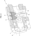
Fig. 3 is a cross-sectional perspective view illustrating the configuration of the cylinder lock according to the present embodiment; -
Fig. 4 is a side view of an inner cylinder according to the present embodiment; -
Fig. 5 is a side view of an outer cylinder according to the present embodiment; -
Fig. 6 is a front view of a driver pin and a tumbler pin according to the present embodiment; and -
Fig. 7 is a front view of a door equipped with the cylinder lock according to the present embodiment. - As illustrated in
Fig. 1 , acylinder lock 10 according to the present embodiment is used in conjunction with anunlocking key 5 capable of locking and unlocking thecylinder lock 10 in a locking device 1. As illustrated inFigs. 1 and2 , thecylinder lock 10 includes aninner cylinder 2, anouter cylinder 3, adecorative member 4, adriver pin 61, and atumbler pin 62. Theinner cylinder 2 rotatably engages with the fixedouter cylinder 3. - As illustrated in
Fig. 2 , theinner cylinder 2 is a substantially cylindrical member that rotatably engages with theouter cylinder 3. The material for theinner cylinder 2 is not particularly limited, and may be composed of metal such as brass, for example. An outerperipheral surface 20 being the sliding surface of theinner cylinder 2 contacts an innerperipheral surface 30 of theouter cylinder 3, and engages with theouter cylinder 3. Akeyhole 21, into which the unlockingkey 5 can be inserted, is formed in theinner cylinder 2 along the axial direction of theinner cylinder 2. - As illustrated in
Fig. 2 , a plurality ofpinholes 22 communicating with thekeyhole 21 are formed in the outerperipheral surface 20 of theinner cylinder 2. At least part of thedriver pin 61 and thetumbler pin 62 can be inserted into and removed from the plurality ofpinholes 22. Each of thepinholes 22 has a cylindrical innerperipheral surface 22a. In the present embodiment, a plurality of rows ofpinholes 22 are formed along the axial direction of theinner cylinder 2, and a plurality of pairs ofpinholes 22 are formed in the circumferential direction of theinner cylinder 2. - As illustrated in
Fig. 4 , aflange 23 is provided on the end face of theinner cylinder 2, on the side of inserting the unlockingkey 5. Theflange 23 may be formed integrally with theinner cylinder 2 or may be a component separate from theinner cylinder 2. Agroove 24, with which a pair of fixingpins 7 can engage, is provided near the end face of theinner cylinder 2, opposite to the side of inserting the unlockingkey 5. In the present embodiment, thegroove 24 is provided along the circumferential direction of theinner cylinder 2. As illustrated inFig. 4 , an indentation having a length L1 in a side view is formed between theflange 23 and the fixing pins 7 engaging with thegroove 24. Part of theouter cylinder 3 engages with indentation, whereby theinner cylinder 2 rotatably engages with theouter cylinder 3. The state of engagement between theinner cylinder 2 and theouter cylinder 3 will be described later in detail. - As illustrated in
Fig. 2 , theouter cylinder 3 is a substantially cylindrical member, in which theinner cylinder 2 can engage withholes 31 formed inside theouter cylinder 3. The material for theouter cylinder 3 is not particularly limited, and may be composed of metal such as brass, for example, as in the case of theinner cylinder 2. Theouter cylinder 3 is fixed and non-rotatable. The innerperipheral surface 30 being the sliding surface of theouter cylinder 3 contacts the outerperipheral surface 20 of theinner cylinder 2, and engages with theinner cylinder 2. - The
holes 31, with which theinner cylinder 2 can engage, are formed in theouter cylinder 3 along the axial direction of theouter cylinder 3. A plurality ofpinholes 32 communicating with theholes 31 are formed in the outer peripheral surface of theouter cylinder 3. At least part of thedriver pin 61 and thetumbler pin 62 can be inserted into and removed from the plurality ofpinholes 32. Each of the plurality ofpinholes 32 has a cylindrical innerperipheral surface 32a. The plurality ofpinholes driver pin 61 and thetumbler pin 62 are insertable and removable when theinner cylinder 2 rotates to a predetermined position relative to theouter cylinder 3. - As illustrated in
Fig. 5 , a pair ofholes 33, through which a pair of fixingpins 7 can be inserted, respectively, are formed in the outer peripheral surface of theouter cylinder 3. Theholes 33 communicate with theholes 31, as in the case of thepinholes 32. Theholes 33 are provided near the end face opposite to theend face 31a of theouter cylinder 3, as illustrated inFig. 5 . - The state of engagement between the
inner cylinder 2 and theouter cylinder 3 is described below. In the positional relationship illustrated inFig. 2 , when theouter cylinder 3 is inserted from the end face side of theinner cylinder 2, which is opposite to the end face including theflange 23, theend face 31a of theouter cylinder 3 illustrated inFig. 5 contacts theinner end face 23a of theflange 23. In this state, when the pair offixing pins 7 are inserted into theholes 33, the pair offixing pins 7 engage with thegroove 24 formed in theinner cylinder 2, as illustrated inFig. 4 . As a result, theinner cylinder 2 engages with theouter cylinder 3. At this time, theinner cylinder 2 needs to be rotatable relative to theouter cylinder 3. Therefore, in the state where the fixing pins 7 are inserted into theouter cylinder 3 as illustrated inFig. 5 , the length L2 between theend face 31a and the edge of the fixing pins 7 is slightly smaller than the length L1 of the indentation, providing a clearance only by the difference between L1 and L2. Therefore, when theinner cylinder 2 engages with theouter cylinder 3, and the unlockingkey 5 is inserted into and removed from thekeyhole 21, the clearance may cause misalignment between thepinholes - As illustrated in
Fig. 1 , thedecorative member 4 covers and decorates the front face of thecylinder lock 10, which is the face on thekeyhole 21 side of theinner cylinder 2 and theouter cylinder 3. Thedecorative member 4 includes a hole communicating with thekeyhole 21. The material for thedecorative member 4 is not particularly limited, and may be composed of metal or the like. A plated layer or the like for enhancing the design may be formed on the surface of thedecorative member 4. Thedecorative member 4 makes theinner cylinder 2 and theouter cylinder 3 almost invisible from the outside. Instead of thedecorative member 4, at least the front part of theinner cylinder 2 and theouter cylinder 3 may be decorated, for example, with a plated layer. - The driver pins 61 and the tumbler pins 62 are members that have a substantially circular columnar shape and are slidably accommodated in the pin holes 22 and 32. The
tumbler pin 62 is arranged on thekeyhole 21 side, has a roundedtip 62b that contacts the unlockingkey 5, and has an enlarged-diameter part 62a at the edge that contacts thedriver pin 61, as illustrated inFig. 6 . Thedriver pin 61 has an edge that contacts thetumbler pin 62, and another edge that contacts an urging member (not illustrated). AlthoughFig. 2 illustrates only one pair of driver pins 61 and one pair of tumbler pins 62 for simplicity, there are a plurality of pairs of driver pins 61 and tumbler pins 62, which are accommodated in the plurality of pairs ofpinholes - In the present embodiment, six rows of driver pins 61 and tumbler pins 62 are arranged in the axial direction of the
circular keyhole 21. The rows of the driver pins 61 and tumbler pins 62 arranged in the axial direction of thekeyhole 21 are not limited to six rows, and can be any number of rows such as three or more rows, for example. - As illustrated in
Fig. 6 , a tapered part 61b1 of thedriver pin 61 contacts a tapered part 62a1 of thetumbler pin 62, thus thedriver pin 61 contacts thetumbler pin 62. In the present embodiment, since theinner cylinder 2 and theouter cylinder 3 are substantially cylindrical, a shear line SL curves along the outerperipheral surface 20 of the inner cylinder 2 (the innerperipheral surface 30 of the outer cylinder 3). Therefore, if the contact portion between thedriver pin 61 and thetumbler pin 62 were made flat, the shape of the contact portion would not match the shape of the shear line SL, thus theinner cylinder 2 could not rotate in synchrony with the unlockingkey 5. Therefore, by providing the tapered parts at the contact portion between thedriver pin 61 and thetumbler pin 62, theinner cylinder 2 can rotate in synchrony with the unlockingkey 5. In the present embodiment, the top of the tapered part 61b1 and the top of the tapered part 62a1 are partially flat. - An urging member (not illustrated) urges the
driver pin 61 towards thekeyhole 21. As illustrated inFig. 3 , when the unlockingkey 5 is not inserted into thekeyhole 21, thedriver pin 61 is positioned between theinner cylinder 2 and theouter cylinder 3, thus restricting the rotation of theinner cylinder 2. In the state where the unlockingkey 5 is inserted into thekeyhole 21, the lengths of thedriver pin 61 and thetumbler pin 62 are set, and the indentations and protrusions formed on the surface of the unlockingkey 5 are set, such that the contact surfaces of thedriver pin 61 and thetumbler pin 62 coincide with the shear line SL being the contact surfaces of theinner cylinder 2 and theouter cylinder 3. By rotating the unlocking key 5 in the state where the contact surfaces of thedriver pin 61 and thetumbler pin 62 align with the shear line SL, theinner cylinder 2 rotates in synchrony with the unlockingkey 5. As a result, for example, the deadbolt of the door can be pulled out or retracted, thereby enabling the locking and unlocking of thecylinder lock 10. - As illustrated in
Fig. 6 , the diameter L41 of thedriver pin 61 near theouter cylinder 3 is larger than the diameter L5 of thedriver pin 61 near theinner cylinder 2. Since the clearance between the diameter L41 and the diameter L3 of thepinhole 32 is reduced from the conventional cases, thedriver pin 61 can be prevented from toppling over inside thepinhole 32, even when the total length of thedriver pin 61 is shortened. Here, a case is described in which the diameter of thedriver pin 61 is maintained constant, and the clearance between the diameter L41 and the diameter L3 of thepinhole 32 is reduced from the conventional cases. In this case, although thedriver pin 61 can be prevented from toppling over inside thepinhole 32, thedriver pin 61 accommodated in thepinhole 32 may not be insertable into thepinhole 22 due to misalignment between thepinholes driver pin 61 near theinner cylinder 2 is smaller than the diameter L41 of thedriver pin 61 near theouter cylinder 3, thedriver pin 61 can be inserted into thepinhole 22, while achieving the effect of preventing the toppling. - In the present embodiment, the
driver pin 61 includes aposture maintaining region 61a and acommunication region 61b. Theposture maintaining region 61a is arranged on theouter cylinder 3 side, and thecommunication region 61b is arranged on theinner cylinder 2 side. - As illustrated in
Fig. 6 , theposture maintaining region 61a preferably has a substantially rectangular shape in a side view, and has a constant diameter L41 over a certain length L42 in the axial direction from the edge of thedriver pin 61 on theouter cylinder 3 side. That is, astep 61c is preferably provided between theposture maintaining region 61a and thecommunication region 61b. As a result, thedriver pin 61 can be effectively prevented from toppling over inside thepinhole 32. Alternatively, theposture maintaining region 61a may have a tapered shape, in which thedriver pin 61 has the largest diameter at the edge of on theouter cylinder 3 side and gradually decreases in diameter towards theinner cylinder 2 side. - In the case in which the
posture maintaining region 61a has the constant diameter L41 over the certain length L42 in the axial direction from the edge of thedriver pin 61 on theouter cylinder 3 side, the ratio of the axial length L42 to the diameter L41, which is the axial length/diameter ratio of theposture maintaining region 61a, is preferably 0.3 or more. As a result, thedriver pin 61 can be prevented from toppling over inside thepinhole 32, and the total length of thedriver pin 61 can be shortened. From the perspective of reliably preventing thedriver pin 61 from toppling over inside thepinhole 32, the axial length/diameter ratio is preferably 0.5 or more. - The
communication region 61b has a constant diameter L5 over a certain length in the axial direction from the edge of thedriver pin 61 on theinner cylinder 2 side. The diameter L5 of thecommunication region 61b is smaller than the diameter L41 of theposture maintaining region 61a. When the unlockingkey 5 is inserted into and removed from thekeyhole 21, thecommunication region 61b enables thedriver pin 61 to be inserted into thepinhole 22, even when misalignment arises between thepinholes - When the diameter L41 of the
posture maintaining region 61a is almost equal to the diameter L3 of thepinhole 32, the difference between the diameter L41 of theposture maintaining region 61a and the diameter L5 of thecommunication region 61b is preferably at least as large as the difference between L1 and L2, corresponding to the clearance between theinner cylinder 2 and theouter cylinder 3. This clearance corresponds to the maximum value of misalignment between thepinholes communication region 61b can be inserted into thepinhole 22, even when misalignment arises between thepinholes - The
posture maintaining region 61a and thecommunication region 61b may be formed as separate components, but are preferably formed integrally from the perspective of ensuring machining accuracy. - The unlocking
key 5 can lock and unlock thecylinder lock 10. In the present embodiment, the insertion part of the unlockingkey 5 into thekeyhole 21 has a circular columnar shape.Fig. 1 illustrates the unlocking key 5 as a blank key. When the unlockingkey 5 is actually applied to thecylinder lock 10, indentations corresponding to the length and arrangement of the driver pins 61 and the tumbler pins 62 of thecylinder lock 10 are formed on the outer peripheral surface of the insertion part. - As illustrated in
Fig. 7 , adoor 100 according to the present embodiment is installed so as to be openable and closable, in a door opening A of a building structure. On the door front side, thedoor 100 includes ahandle 9 for opening and closing thedoor 100, and a pair ofcylinder locks 10 arranged above and below thehandle 9. Thedoor 100 is used, for example, as a front door. - The cylinder lock and the door according to the embodiment of the present disclosure have been described above. However, the present disclosure is not limited to the embodiments and can be modified as appropriate.
- In the embodiment described above, the
communication region 61b has the constant diameter L5 over a certain length in the axial direction from the edge of thedriver pin 61 on theinner cylinder 2 side. This is a non-limiting example. Thecommunication region 61b may have varying diameters in the axial direction, by having a tapered shape, for example.
Claims (5)
- A cylinder lock, comprising:an outer cylinder; andan inner cylinder rotatably engaging with the outer cylinder, whereina hole is formed in the outer cylinder and the inner cylinder, in which the hole communicates with a keyhole, and a driver pin can be inserted through the hole, anda diameter of the driver pin on a side of the outer cylinder is larger than a diameter of the driver pin on a side of the inner cylinder.
- The cylinder lock according to claim 1, wherein
the driver pin includes:a posture maintaining region that has a constant diameter over a certain length in an axial direction from an edge of the driver pin on the side of the outer cylinder;a communication region on the side of the inner cylinder; anda step between the posture maintaining region and the communication region. - The cylinder lock according to claim 2, wherein
an axial length/diameter ratio, which is a ratio of an axial length to a diameter of the posture maintaining region, is 0.3 or more. - The cylinder lock according to any one of claims 1 to 3, whereina length L2 of a portion where the outer cylinder engages with the inner cylinder is shorter than a length L1 of a portion where the inner cylinder engages with the outer cylinder, forming a clearance corresponding to a difference between L1 and L2, anda difference between the diameter of the driver pin on the side of the outer cylinder and the diameter of the driver pin on the side of the inner cylinder is a length of at least as long as the clearance.
- A door comprising the cylinder lock according to any one of claims 1 to 4.
Applications Claiming Priority (2)
| Application Number | Priority Date | Filing Date | Title |
|---|---|---|---|
| JP2021195253A JP7822759B2 (en) | 2021-12-01 | 2021-12-01 | Cylinder locks and doors |
| PCT/JP2022/043707 WO2023100787A1 (en) | 2021-12-01 | 2022-11-28 | Cylinder lock and door |
Publications (2)
| Publication Number | Publication Date |
|---|---|
| EP4442938A1 true EP4442938A1 (en) | 2024-10-09 |
| EP4442938A4 EP4442938A4 (en) | 2025-11-05 |
Family
ID=86612222
Family Applications (1)
| Application Number | Title | Priority Date | Filing Date |
|---|---|---|---|
| EP22901220.8A Pending EP4442938A4 (en) | 2021-12-01 | 2022-11-28 | CYLINDER LOCK AND DOOR |
Country Status (5)
| Country | Link |
|---|---|
| US (1) | US12618265B2 (en) |
| EP (1) | EP4442938A4 (en) |
| JP (2) | JP7822759B2 (en) |
| CN (1) | CN118302584A (en) |
| WO (1) | WO2023100787A1 (en) |
Family Cites Families (20)
| Publication number | Priority date | Publication date | Assignee | Title |
|---|---|---|---|---|
| US2059129A (en) * | 1933-04-22 | 1936-10-27 | Yale & Towne Mfg Co | Lock |
| US2111098A (en) * | 1937-12-29 | 1938-03-15 | Segal Samuel | Pickproof lock |
| US2283489A (en) * | 1940-06-27 | 1942-05-19 | Crousore Ralph Paul | Pin and cylinder lock |
| US2687640A (en) * | 1952-10-25 | 1954-08-31 | Mir Antonio Juan | Cylinder lock |
| US3590615A (en) * | 1970-02-16 | 1971-07-06 | Eaton Yale & Towne | Antipick lock |
| US4341102A (en) * | 1978-06-26 | 1982-07-27 | Ku Chung C | Construction for a cylinder lock and key |
| JP3283741B2 (en) * | 1995-12-20 | 2002-05-20 | 株式会社アルファ | Cylinder lock |
| JP2002256735A (en) * | 2001-03-05 | 2002-09-11 | Takigen Mfg Co Ltd | Cylinder lock device |
| JP4062656B2 (en) * | 2001-03-22 | 2008-03-19 | 美和ロック株式会社 | Multi-pin cylinder lock |
| WO2004029390A1 (en) * | 2002-09-25 | 2004-04-08 | Malachi Christopher Mckenna | Lock with different keys |
| IL159921A0 (en) * | 2004-01-18 | 2004-06-20 | Mul T Lock Technologies Ltd | Cylinder lock with extensible lock pin |
| JP2007239265A (en) * | 2006-03-07 | 2007-09-20 | Sankyo Kinzoku Kk | Cylinder lock |
| JPWO2008050464A1 (en) * | 2006-10-25 | 2010-02-25 | 株式会社エイ・エス・アイ | Anti bump key cylinder |
| JP4931569B2 (en) * | 2006-12-12 | 2012-05-16 | 株式会社ファースト・ロック | Locking mechanism |
| JP5091753B2 (en) * | 2008-04-24 | 2012-12-05 | 株式会社ファースト・ロック | Pin tumbler tablets |
| GB2453623B (en) * | 2008-09-03 | 2009-08-26 | Assa Abloy Ltd | Cylinder assemblies |
| CN102400596A (en) * | 2011-11-18 | 2012-04-04 | 钟永颂 | Tumbler lock |
| GB2506580B (en) * | 2012-08-15 | 2017-05-31 | Eric Belcher Christopher | Improvements to key-operated pin tumbler locks |
| JP6463290B2 (en) * | 2016-03-03 | 2019-01-30 | 株式会社ゴール | Construction master device |
| GB2619522B (en) * | 2022-06-07 | 2025-01-22 | Apecs Consult Ltd | Pin for pin tumbler lock |
-
2021
- 2021-12-01 JP JP2021195253A patent/JP7822759B2/en active Active
-
2022
- 2022-11-28 WO PCT/JP2022/043707 patent/WO2023100787A1/en not_active Ceased
- 2022-11-28 EP EP22901220.8A patent/EP4442938A4/en active Pending
- 2022-11-28 US US18/715,269 patent/US12618265B2/en active Active
- 2022-11-28 CN CN202280077853.8A patent/CN118302584A/en active Pending
-
2026
- 2026-02-18 JP JP2026024716A patent/JP2026069652A/en active Pending
Also Published As
| Publication number | Publication date |
|---|---|
| JP7822759B2 (en) | 2026-03-03 |
| EP4442938A4 (en) | 2025-11-05 |
| CN118302584A (en) | 2024-07-05 |
| US20250027337A1 (en) | 2025-01-23 |
| JP2026069652A (en) | 2026-04-23 |
| US12618265B2 (en) | 2026-05-05 |
| WO2023100787A1 (en) | 2023-06-08 |
| JP2023081497A (en) | 2023-06-13 |
Similar Documents
| Publication | Publication Date | Title |
|---|---|---|
| US6490898B1 (en) | Cylinder lock | |
| US8978426B2 (en) | Hidden shackle lock incorporating a “key-in-knob” (KiK) cylinder | |
| US7866194B2 (en) | Unlocking device for concealing keyhole of lock | |
| US3765199A (en) | Lock anti-pick device | |
| JP7801981B2 (en) | Locking devices and unlocking keys, and doors | |
| US5400629A (en) | Axial pin tumbler lock | |
| CA2639167C (en) | Cylinder lock assembly with a tailpiece rotationally coupled to the cylinder plug | |
| US5758526A (en) | Lock | |
| US12618265B2 (en) | Cylinder lock and door | |
| EP2865826B1 (en) | Cylinder lock arrangement | |
| EP2865825B1 (en) | Cylinder lock arrangement | |
| EP1582667A2 (en) | A locking device for a sliding shutter | |
| EP2530224A2 (en) | Anti-tamper lock | |
| EP2865827B1 (en) | Cylinder lock arrangement | |
| EP4442939A1 (en) | Cylinder lock and door | |
| GB2421540A (en) | Padlock comprising adaptor member | |
| EP2278099A1 (en) | A cylinder lock | |
| WO2020016568A1 (en) | Lock mechanism | |
| GB2358670A (en) | Key and cylinder lock | |
| WO2001038674A1 (en) | Lock cylinder, plug therefor, and method of manufacturing | |
| EP2865830B1 (en) | Cylinder lock arrangement | |
| JPH0726490B2 (en) | Locking device | |
| JP2006070554A (en) | Cylinder lock |
Legal Events
| Date | Code | Title | Description |
|---|---|---|---|
| STAA | Information on the status of an ep patent application or granted ep patent |
Free format text: STATUS: THE INTERNATIONAL PUBLICATION HAS BEEN MADE |
|
| PUAI | Public reference made under article 153(3) epc to a published international application that has entered the european phase |
Free format text: ORIGINAL CODE: 0009012 |
|
| STAA | Information on the status of an ep patent application or granted ep patent |
Free format text: STATUS: REQUEST FOR EXAMINATION WAS MADE |
|
| 17P | Request for examination filed |
Effective date: 20240612 |
|
| AK | Designated contracting states |
Kind code of ref document: A1 Designated state(s): AL AT BE BG CH CY CZ DE DK EE ES FI FR GB GR HR HU IE IS IT LI LT LU LV MC ME MK MT NL NO PL PT RO RS SE SI SK SM TR |
|
| DAV | Request for validation of the european patent (deleted) | ||
| DAX | Request for extension of the european patent (deleted) | ||
| A4 | Supplementary search report drawn up and despatched |
Effective date: 20251009 |
|
| RIC1 | Information provided on ipc code assigned before grant |
Ipc: E05B 27/06 20060101AFI20251002BHEP Ipc: E05B 27/00 20060101ALI20251002BHEP |