Cross-Reference to Related Applications
-
The entire disclosure of
Japanese Patent Application No. 2023-061958, filed on April 6, 2023 , is incorporated herein by reference in its entirety.
Background
Technological Field
-
The present invention relates to a sheet conveyance device.
Description of the Related Art
-
Conventionally, there has been known a textile-printing inkjet printer that performs textile-printing on a sheet such as a fabric cloth by ejecting ink onto the sheet. This type of inkjet recording apparatus includes a sheet conveyance device that conveys, in a predetermined conveyance direction, an elongated roll-shaped sheet or separate-type sheet supplied to the device.
-
In the sheet conveyance device, the sheet is conveyed, for example, in the following manner: a conveyance belt is circulated with the sheet being placed on the conveyance belt; or a conveyance drum is rotated around its axis with the sheet being placed on a main surface of the conveyance drum.
-
As an exemplary method of holding the sheet on the conveyance belt or the conveyance drum, there is a method of adhering the sheet to an adhesive agent layer provided on a surface of the conveyance belt or the like. For example, in a sheet conveyance device disclosed in
Japanese Laid-Open Patent Publication No. 8-175716 , a pressing roller, which is disposed to face the conveyance belt and is reciprocated with respect to a sheet conveyance direction, is pressed against the sheet placed on the conveyance belt, thereby adhering the sheet to the adhesive agent layer.
Summary
-
However, in the sheet conveyance device disclosed in the above-mentioned publication, the pressing roller is temporarily stopped with the pressing roller being pressed against the sheet at each of both ends of a trajectory on which the pressing roller is reciprocated (i.e., at positions at each of which the reciprocation is changed in direction). A portion of the sheet pressed by the pressing roller stopped is more firmly adhered to the adhesive agent layer than the other portion of the sheet. This results in unevenness in strength of adhesion of the sheet to the adhesive agent layer.
-
When such unevenness occurs, the sheet is less likely to be uniformly detached from the conveyance belt. As a result, when detaching the sheet from the conveyance belt, the sheet may be wrinkled or may be unintentionally stretched disadvantageously, with the result that it becomes difficult for the sheet conveyance device to stably convey the sheet.
-
Thus, the present invention has been made in view of the above-described point, and has an object to realize stable conveyance of a sheet in a sheet conveyance device including a pressing roller reciprocated with respect to a conveyance direction of the sheet.
-
To achieve at least one of the abovementioned objects, according to an aspect of the present invention, a sheet conveyance device reflecting a first aspect of the present invention comprises: a conveyance belt that has a front surface provided with an adhesive agent layer and a rear surface located opposite to the front surface and that conveys, in a predetermined conveyance direction, a sheet placed on the adhesive agent layer; a pressing roller disposed to face the front surface; and a contact portion in contact with the rear surface. The pressing roller is reciprocated in a forward direction and a reverse direction with respect to the conveyance direction so as to pass through an adhesion region in which the sheet placed on the adhesive agent layer is adhered to the adhesive agent layer. In the adhesion region, the pressing roller and the contact portion sandwich the sheet placed on the adhesive agent layer and the conveyance belt. When the pressing roller passes through each of a pair of end portions of the adhesion region in a reciprocation direction of the pressing roller, the pressing roller passes through each of the pair of end portions at speed to leave the adhesion region.
-
To achieve at least one of the abovementioned objects, according to an aspect of the present invention, a sheet conveyance device reflecting a second aspect of the present invention comprises: a conveyance section that has a main surface provided with an adhesive agent layer and that conveys, in a predetermined conveyance direction, a sheet placed on the adhesive agent layer; and a pressing roller disposed to face the main surface. The pressing roller is reciprocated in a forward direction and a reverse direction with respect to the conveyance direction so as to pass through an adhesion region in which the sheet placed on the adhesive agent layer is adhered to the adhesive agent layer. In the adhesion region, the pressing roller and the conveyance section sandwich the sheet placed on the adhesive agent layer. When the pressing roller passes through each of a pair of end portions of the adhesion region in a reciprocation direction of the pressing roller, the pressing roller passes through each of the pair of end portions at speed to leave the adhesion region.
-
To achieve at least one of the abovementioned objects, according to an aspect of the present invention, a sheet conveyance device reflecting a third aspect of the present invention comprises: a conveyance belt that has a front surface provided with an adhesive agent layer and a rear surface located opposite to the front surface and that conveys, in a predetermined conveyance direction, a sheet placed on the adhesive agent layer; a pressing roller disposed to face the front surface; and a contact portion in contact with the rear surface. The pressing roller is reciprocated in a forward direction and a reverse direction with respect to the conveyance direction in an adhesion region in which the sheet placed on the adhesive agent layer is adhered to the adhesive agent layer. In the adhesion region, the pressing roller and the contact portion sandwich the sheet placed on the adhesive agent layer and the conveyance belt. A region of a portion of at least one of the pressing roller and the contact portion to sandwich the sheet is constituted of a soft portion that is softer than another region of the portion to sandwich the sheet. When the pressing roller passes through each of a pair of end portions of the adhesion region in a reciprocation direction of the pressing roller, the sheet placed on the adhesive agent layer is sandwiched between the pressing roller and the contact portion with the sheet placed on the adhesive agent layer being in abutment with the soft portion.
Brief Description of the Drawings
-
The advantages and features provided by one or more embodiments of the invention will become more fully understood from the detailed description given hereinbelow and the appended drawings which are given by way of illustration only, and thus are not intended as a definition of the limits of the present invention.
- Fig. 1 is a schematic diagram illustrating an internal structure of a textile-printing inkjet printer according to a first embodiment.
- Fig. 2 is a schematic diagram illustrating a configuration of a sheet conveyance device illustrated in Fig. 1.
- Fig. 3 is a schematic cross sectional view of a conveyance belt and a sheet illustrated in Fig. 2.
- Fig. 4 is a flowchart illustrating operation states of the sheet conveyance device illustrated in Fig. 1 in time series.
- Fig. 5 is a schematic diagram for illustrating a time point of the flowchart illustrated in Fig. 4.
- Fig. 6 is a schematic diagram for illustrating a time point of the flowchart illustrated in Fig. 4.
- Fig. 7 is a schematic diagram for illustrating a time point of the flowchart illustrated in Fig. 4.
- Fig. 8 is a schematic diagram for illustrating a time point of the flowchart illustrated in Fig. 4.
- Fig. 9 is a schematic diagram for illustrating a time point of the flowchart illustrated in Fig. 4.
- Fig. 10 is a schematic diagram for illustrating a time point of the flowchart illustrated in Fig. 4.
- Fig. 11 is a schematic diagram illustrating a configuration of a sheet conveyance device according to a first modification example.
- Figs. 12A and 12B are schematic diagrams illustrating configurations of a sheet conveyance device and a pressing roller according to a second modification example.
- Figs. 13A and 13B are schematic diagrams each illustrating a configuration of a sheet conveyance device according to a third modification example.
- Figs. 14A and 14B are schematic diagrams each illustrating a configuration of a sheet conveyance device according to a second embodiment.
- Figs. 15A and 15B are schematic diagrams each illustrating a configuration of a sheet conveyance device according to a fourth modification example.
- Fig. 16 is a schematic diagram illustrating a configuration of a sheet conveyance device according to a third embodiment.
- Fig. 17 is a schematic diagram illustrating a configuration of a sheet conveyance device according to a fifth modification example.
- Fig. 18 is a schematic diagram illustrating a configuration of a sheet conveyance device according to a fourth embodiment.
- Figs. 19A and 19B are schematic diagrams each illustrating a configuration of a sheet conveyance device according to a fifth embodiment.
- Figs. 20A and 20B are schematic diagrams each illustrating a configuration of a sheet conveyance device according to a sixth modification example.
- Fig. 21 is a schematic diagram illustrating a configuration of a sheet conveyance device according to a sixth embodiment.
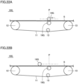
- Figs. 22A and 22B are schematic diagrams each illustrating a configuration of a sheet conveyance device according to a seventh embodiment.
Detailed Description of Embodiments
-
Hereinafter, one or more embodiments of the present invention will be described with reference to the drawings. However, the scope of the invention is not limited to the disclosed embodiments.
-
Hereinafter, embodiments of the present invention will be described in detail with reference to figures. It should be noted that in the embodiments described below, the same or common portions are denoted by the same reference signs in the figures and will not be described repeatedly.
(First Embodiment)
-
Fig. 1 is a schematic diagram illustrating an internal structure of a textile-printing inkjet printer according to a first embodiment. First, a schematic configuration of a textile-printing inkjet printer 1A according to the present embodiment will be described with reference to Fig. 1.
-
As illustrated in Fig. 1, the textile-printing inkjet printer 1A includes a sheet conveyance device 10A, a carriage 20, a plurality of conveyance rollers 30, and a controller 40.
-
The sheet conveyance device 10A conveys, in a predetermined conveyance direction, a sheet S supplied thereto. A configuration of the sheet conveyance device 10A will be described in detail later.
-
Examples of the sheet S usable herein include: a fabric cloth; a resin film such as a PET film, a PP film, or a PE film; plain paper; and the like. In the present embodiment, an elongated roll-shaped fabric cloth is used as the sheet S. The sheet S is wound around an unwinding roller (not illustrated) in the form of a roll, and is wound by a winding roller (not illustrated). It should be noted that the sheet S is not particularly limited to the elongated roll-shaped sheet, and may be an elongated folded sheet.
-
The carriage 20 is movable in a direction orthogonal to the conveyance direction in which the sheet S is conveyed by a below-described conveyance belt 11 of the sheet conveyance device 10A. The carriage 20 is disposed to face the conveyance belt 11. Inside the carriage 20, a plurality of inkjet heads 21 are provided.
-
The plurality of inkjet heads 21 perform textile-printing onto the sheet S by ejecting ink onto the sheet S conveyed by the below-described conveyance belt 11 of the sheet conveyance device 10A. The plurality of inkjet heads 21 are provided in the carriage 20 so as to be disposed to face the conveyance belt 11. Thus, the plurality of inkjet heads 21 can scan the sheet S in the direction orthogonal to the conveyance direction in which the sheet S is conveyed by the conveyance belt 11. In the present embodiment, four inkjet heads 21 are disposed side by side along the conveyance direction in which the sheet S is conveyed by the conveyance belt 11. The four inkjet heads 21 eject yellow (Y) ink, magenta (M) ink, cyan (C) ink, and black (K) ink, respectively.
-
The plurality of conveyance rollers 30 and the sheet conveyance device 10A convey the sheet S. In the present embodiment, two conveyance rollers 30 are disposed at predetermined positions. Each of two conveyance rollers 30 is rotated around its axis.
-
The controller 40 controls driving of a below-described driving roller 12, reciprocation of a below-described pressing roller 14, and the like of the sheet conveyance device 10A.
-
The controller 40 has, as main constituent elements, a central processing unit (CPU) that executes a program, a read only memory (ROM)/random access memory (RAM), an arithmetic section that performs various arithmetic operations based on input information, and the like. The ROM/RAM includes a ROM that stores data in a nonvolatile manner and a RAM that stores, in a volatile manner, data generated by the execution of the program by the CPU. The constituent elements of the controller 40 are connected to one another by a data bus.
-
Processing in the CPU is implemented by each hardware and software executed by the CPU. Such software is stored in the ROM/RAM in advance.
-
Power is supplied to the controller 40 by an internal power supply (not illustrated) or an external power supply (not illustrated). For connection to the external power supply, for example, an AC adapter (not illustrated) or the like is used.
-
Fig. 2 is a schematic diagram illustrating a configuration of the sheet conveyance device illustrated in Fig. 1. Fig. 3 is a schematic cross sectional view of the conveyance belt and the sheet along a line III-III illustrated in Fig. 2. Next, referring to Figs. 2 and 3, the following describes a configuration of the sheet conveyance device 10A included in the textile-printing inkjet printer 1A according to the present embodiment.
-
As illustrated in Figs. 2 and 3, the sheet conveyance device 10A includes the conveyance belt 11, the driving roller 12, two driven rollers 13, the pressing roller 14, and a contact portion 15.
-
The conveyance belt 11 has a front surface 11a and a rear surface 11b located opposite to the front surface 11a. The front surface 11a is provided with an adhesive agent layer 17. The conveyance belt 11 conveys, in the predetermined conveyance direction (i.e., in the leftward direction in Fig. 2), the sheet S placed on the adhesive agent layer 17.
-
A material of the conveyance belt 11 is not particularly limited, and various materials such as a metal, a rubber, and a resin can be used therefor. The adhesive agent layer 17 can be formed by, for example, applying a pressure-sensitive type adhesive agent or a heat-sensitive type adhesive agent to the front surface 11a of the conveyance belt 11. The pressure-sensitive type adhesive agent is an adhesive agent that adheres a target object by pressing the target object thereagainst. The heat-sensitive type adhesive agent is an adhesive agent that adheres it by heating, to an appropriate temperature using a belt heater or the like (not illustrated), the conveyance belt 11 having the heat-sensitive type adhesive agent applied thereon.
-
The conveyance belt 11 is held by: the driving roller 12 that drives the conveyance belt 11; and the two driven rollers 13 that are each rotated according to the rotation of the driving roller 12. The conveyance belt 11 is driven to circulate by the driving roller 12 being driven. The driving roller 12 is driven to rotate by a motor or the like (not illustrated). The driving of the driving roller 12 is controlled by the controller 40.
-
The pressing roller 14 is disposed to face the front surface 11a of the conveyance belt 11. The pressing roller 14 is configured to be reciprocated in a forward direction and a reverse direction with respect to the conveyance direction of the sheet S. The pressing roller 14 is rotatably supported by a bearing (not illustrated). In Fig. 2, a trajectory on which the pressing roller 14 is reciprocated is indicated by an imaginary line (alternate long and short dash line) (the same applies to Figs. 5 to 20B described below).
-
It should be noted that hereinafter, the trajectory of the pressing roller 14 moving in the forward direction (i.e., the leftward direction in Fig. 2) with respect to the conveyance direction of the sheet S is referred to as an outbound path of the pressing roller 14. Similarly, the trajectory of the pressing roller 14 moving in the reverse direction (i.e., the rightward direction in Fig. 2) with respect to the conveyance direction of the sheet S is referred to as a return path of the pressing roller 14. Further, the trajectory of the pressing roller 14 has a pair of end portions, which are referred to as follows: an upstream end of the trajectory, which is an end portion located on the upstream side in the conveyance direction (i.e., the right end in Fig. 2); and a downstream end of the trajectory, which is an end portion located on the downstream side in the conveyance direction (i.e., the left end in Fig. 2).
-
The contact portion 15 is in contact with the rear surface 11b of the conveyance belt 11. More specifically, the contact portion 15 is provided along the conveyance belt 11 in contact with the rear surface 11b of the conveyance belt 11 at a portion corresponding to the trajectory on which the pressing roller 14 is reciprocated. In the present embodiment, a plate-shaped object is used as the contact portion 15. A material of the contact portion 15 is not particularly limited, and various materials such as a metal and a resin can be used therefor.
-
The pressing roller 14 is reciprocated in the forward direction and the reverse direction with respect to the conveyance direction so as to pass through an adhesion region P (see Fig. 2) in which the sheet S placed on the adhesive agent layer 17 is adhered to the adhesive agent layer 17. In the adhesion region P, the pressing roller 14 and the contact portion 15 sandwich the sheet S placed on the adhesive agent layer 17 and the conveyance belt 11.
-
Here, the pressing roller 14 is moved in a direction away from the conveyance belt 11 at each of predetermined positions (see a position L1 and a position L2 in Fig. 2) on the outbound path and the return path in the reciprocation direction. By moving the pressing roller 14 in this way, the sandwiching of the sheet S by the pressing roller 14 and the contact portion 15 is released. Therefore, the pair of end portions of the adhesion region P are defined by the predetermined positions.
-
When the pressing roller 14 passes through each of the pair of end portions of the adhesion region P in the reciprocation direction, the pressing roller 14 passes through each of the pair of end portions at speed to leave the adhesion region P. With such a configuration, stable conveyance of the sheet S can be realized in the sheet conveyance device 10A, and this point will be described in detail later.
-
Further, as described above, the pressing roller 14 is rotatably supported by the bearing. The pressing roller 14 thus configured is rotated with the pressing roller 14 pressing the sheet S when passing through the adhesion region P. Thus, it is possible to effectively suppress occurrence of a scratch or damage on the sheet S.
-
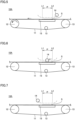
Fig. 4 is a flowchart illustrating operation states of the sheet conveyance device illustrated in Fig. 1 in time series. Each of Figs. 5 to 10 is a schematic diagram for illustrating a time point of the flowchart illustrated in Fig. 4. Next, the operation of the sheet conveyance device 10A according to the present embodiment will be described with reference to Figs. 4 to 10. It should be noted that in Figs. 5 to 10, for ease of understanding, a solid line represents only a portion to be adhered to the adhesive agent layer 17 by a series of operations by the pressing roller 14 in the sheet S continuously extending from the above-described unwinding roller to the winding roller, and a broken line represents the other portion thereof.
-
First, as illustrated in Figs. 4 and 5, at a time point T1, the conveyance belt 11 starts to be driven.
-
More specifically, first, the controller 40 starts to drive the driving roller 12. Thus, the conveyance belt 11 is driven at a predetermined speed to circulate, with the result that the sheet S is conveyed in the conveyance direction by a predetermined distance. It should be noted that at the time point T1, the pressing roller 14 is located at the upstream end of the trajectory.
-
Next, as illustrated in Fig. 4, at a time point T2, the driving of the conveyance belt 11 is stopped. More specifically, the controller 40 stops the driving of the driving roller 12. Thus, the conveyance of the sheet S by the conveyance belt 11 is stopped.
-
Next, as illustrated in Figs. 4 and 6, at a time point T3, the movement of the pressing roller 14 on the outbound path is started.
-
More specifically, the controller 40 starts reciprocation of the pressing roller 14. Thus, the pressing roller 14 is moved in the forward direction with respect to the conveyance direction in which the sheet S is conveyed by the conveyance belt 11 and passes through the adhesion region P. During this passing, the sheet S placed on the adhesive agent layer 17 and the conveyance belt 11 are sandwiched by the pressing roller 14 and the contact portion 15. Thus, the sheet S is adhered to the adhesive agent layer 17.
-
At the position L1 of the outbound path, the pressing roller 14 is moved in the direction away from the conveyance belt 11. Thus, the pressing roller 14 passes, at speed, through one of the pair of end portions of the adhesion region P defined by the position L1, to leave the adhesion region P.
-
Next, as illustrated in Figs. 4 and 7, at a time point T4, the movement of the pressing roller 14 on the outbound path is completed. More specifically, when the pressing roller 14 reaches the downstream end of the trajectory, the movement of the pressing roller 14 on the outbound path is completed.
-
Next, as illustrated in Figs. 4 and 8, at a time point T5, the movement of the pressing roller 14 on the return path is started.
-
More specifically, the pressing roller 14 is moved in the reverse direction with respect to the conveyance direction in which the sheet S is conveyed by the conveyance belt 11 and passes through the adhesion region P. During this passing, the sheet S placed on the adhesive agent layer 17 and the conveyance belt 11 are sandwiched again by the pressing roller 14 and the contact portion 15. Thus, the sheet S adhered to the adhesive agent layer 17 by the pressing roller 14 and the contact portion 15 during the movement of the pressing roller 14 on the outbound path is more firmly adhered to the portion of the adhesive agent layer 17.
-
At the position L2 of the return path, the pressing roller 14 is moved in the direction away from the conveyance belt 11. Thus, the pressing roller 14 passes, at speed, through the other of the pair of end portions of the adhesion region P defined by the position L2, to leave the adhesion region P.
-
Next, as illustrated in Figs. 4 and 9, the movement of the pressing roller 14 on the return path is completed at a time point T6. More specifically, when the pressing roller 14 reaches the upstream end of the trajectory, the movement of the pressing roller 14 on the return path is completed.
-
Next, as illustrated in Figs. 4 and 10, returning to the time point T1, the driving of the conveyance belt 11 is started. Thus, the portion of the sheet S adhered to the adhesive agent layer 17 at the time points T3 to T6 is conveyed by a predetermined length in the conveyance direction. By repeating the operations at the time points T1 to T6 in this way, portions of the elongated roll-shaped sheet S sent out to the conveyance belt 11 can be sequentially adhered to the adhesive agent layer 17.
-
With the above-described configuration, stable conveyance of the sheet S can be realized in each of the sheet conveyance device 10A including the pressing roller 14 reciprocated with respect to the conveyance direction of the sheet S and the textile-printing inkjet printer 1A including the sheet conveyance device 10A.
-
That is, in the sheet conveyance device 10A according to the present embodiment, as described above, when the pressing roller 14 passes through each of the pair of end portions of the adhesion region P in the reciprocation direction of the pressing roller 14, the pressing roller 14 passes through each of the pair of end portions at speed to leave the adhesion region P.
-
With the above-described configuration, it is possible to avoid the pressing roller 14 from being stopped with the pressing roller 14 being pressed against the sheet S at each of the both ends of the trajectory of the reciprocation. Therefore, it is possible to effectively suppress occurrence of unevenness in the strength of adhesion of the sheet S to the adhesive agent layer 17, with the result that when detaching the sheet S from the conveyance belt 11, a wrinkle can be prevented in advance from being formed in the sheet S or the sheet S can be prevented in advance from being unintentionally stretched.
-
Therefore, with such a configuration, it is possible to realize stable conveyance of the sheet in each of the sheet conveyance device including the pressing roller reciprocated with respect to the conveyance direction of the sheet and the textile-printing inkjet printer including the sheet conveyance device.
-
Further, if ink is ejected onto the sheet by an inkjet head in a state involving the unevenness in the strength of adhesion of the sheet to the adhesive agent layer, there is such a concern that a streak resulting from the unevenness is formed on the sheet; however, in the textile-printing inkjet printer 1A including the sheet conveyance device 10A according to the present embodiment, it is possible to effectively suppress formation of such a streak on the sheet S.
-
It should be noted that in the sheet conveyance device 10A according to the present embodiment, it has been illustratively described that the pressing roller 14 is reciprocated once to adhere the sheet S to the adhesive agent layer 17; however, the pressing roller 14 may be reciprocated a plurality of times to adhere the sheet S to the adhesive agent layer 17.
-
Further, in the sheet conveyance device 10A according to the present embodiment, it has been illustratively described that the start position of the reciprocation of the pressing roller 14 is the upstream end of the trajectory; however, the start position of the reciprocation may be the downstream end of the trajectory.
-
Further, in the sheet conveyance device 10A according to the present embodiment, it has been illustratively described that the sheet S is an elongated roll-shaped sheet on the conveyance belt 11; however, the sheet S may be a plurality of separate-type sheets or may be a folded elongated sheet.
-
Furthermore, in the sheet conveyance device 10A according to the present embodiment, it has been illustratively described that the driving or the like of the driving roller 12 is controlled by the controller 40 included in the textile-printing inkjet printer 1A; however, the controller that controls the driving or the like of the driving roller 12 may be provided in the sheet conveyance device 10A.
(First Modification Example)
-
Fig. 11 is a schematic diagram illustrating a configuration of a sheet conveyance device according to a first modification example. Referring to Fig. 11, the following describes a textile-printing inkjet printer and a sheet conveyance device 10A1 included therein according to the first modification example that is based on the first embodiment.
-
As illustrated in Fig. 11, the sheet conveyance device 10A1 according to the first modification example is different from the sheet conveyance device 10A according to the first embodiment in terms of a trajectory of a pressing roller 14A1 and a configuration of a contact portion 15A1.
-
The pressing roller 14A1 according to the first modification example is not moved in the direction away from the conveyance belt 11. That is, the pressing roller 14A1 is movable only along a direction substantially parallel to the conveyance direction in which the sheet S is conveyed by the conveyance belt 11.
-
The contact portion 15A1 according to the first modification example includes: an abutment surface 15a in abutment with the conveyance belt 11; and a pair of retraction surfaces 15b that sandwich the abutment surface 15a in the conveyance direction. The pair of retraction surfaces 15b are inclined to be farther away from the conveyance belt 11 in a direction away from the abutment surface 15a such that each of the pair of retraction surfaces 15b is located at a distance from the conveyance belt 11.
-
When the pressing roller 14A1 is located on the conveyance belt 11 at a portion corresponding to each of the retraction surfaces 15b thus configured, the sandwiching of the sheet S by the pressing roller 14A1 and the contact portion 15A1 is released. Thus, each of the pair of end portions of the adhesion region P is defined by a boundary portion between the abutment surface 15a and a corresponding one of the pair of retraction surfaces 15b (see a boundary portion B1 and a boundary portion B2 in Fig. 11).
-
In the sheet conveyance device 10A1 configured as described above, when the pressing roller 14A1 passes through each of the pair of end portions of the adhesion region P in the reciprocation direction of the pressing roller 14A1, the pressing roller 14A1 passes through each of the pair of end portions at speed to leave the adhesion region P.
-
Also with the such a configuration, an effect comparable to the effect described in the first embodiment can be obtained, with the result that stable conveyance of the sheet can be realized in each of the sheet conveyance device including the pressing roller reciprocated with respect to the conveyance direction of the sheet and the textile-printing inkjet printer including the sheet conveyance device.
-
Further, with such a configuration, it is not necessary to move the pressing roller 14A1 in the direction away from the conveyance belt 11. Therefore, as compared with the sheet conveyance device 10A according to the first embodiment, it is possible to attain a reduced size of the device in the height direction (i.e., the upward/downward direction in Fig. 11), thereby reducing manufacturing cost of the device.
(Second Modification Example)
-
Figs. 12A and 12B are schematic diagrams illustrating configurations of a sheet conveyance device and a pressing roller according to a second modification example. Referring to Figs. 12A and 12B, the following describes a textile-printing inkjet printer and a sheet conveyance device 10A2 included therein according to the second modification example that is based on the first embodiment.
-
As illustrated in Figs. 12A and 12B, the sheet conveyance device 10A2 according to the second modification example is different from the sheet conveyance device 10A according to the first embodiment in terms of trajectory and configuration of a pressing roller 14A2.
-
The pressing roller 14A2 according to the second modification example is not moved in the direction away from the conveyance belt 11. That is, the pressing roller 14A2 is movable only along a direction substantially parallel to the conveyance direction in which the sheet S is conveyed by the conveyance belt 11.
-
An outer peripheral surface of the pressing roller 14A2 is provided with one cutout portion 14a in the form of a recess. Thus, a distance between the cutout portion 14a and the center of axis of the pressing roller 14A2 is shorter than a distance between an outer peripheral surface of a portion other than the cutout portion 14a and the center of axis. A peripheral length p (see Fig. 12B) of the portion of the pressing roller 14A2 other than the cutout portion 14a coincides with the length of the adhesion region P.
-
Since the pressing roller 14A2 is thus configured, as the pressing roller 14A2 is rotated, the cutout portion 14a faces the conveyance belt 11 at each of predetermined positions (see a position L3 and a position L4 in Fig. 12A) on the outbound path and the return path in the reciprocation direction. Since the cutout portion 14a thus faces the conveyance belt 11, the sandwiching of the sheet S by the pressing roller 14A2 and the contact portion 15 is released. Therefore, the pair of end portions of the adhesion region P are defined by the predetermined positions.
-
In the sheet conveyance device 10A2 configured as described above, when the pressing roller 14A2 passes through each of the pair of end portions of the adhesion region P in the reciprocation direction of the pressing roller 14A2, the pressing roller 14A2 passes through each of the pair of end portions at speed to leave the adhesion region P.
-
Also with such a configuration, an effect comparable to the effect described in the first embodiment can be obtained, with the result that stable conveyance of the sheet can be realized in each of the sheet conveyance device including the pressing roller reciprocated with respect to the conveyance direction of the sheet and the textile-printing inkjet printer including the sheet conveyance device.
-
Furthermore, with such a configuration, it is not necessary to move the pressing roller 14A2 in the direction away from the conveyance belt 11. Therefore, as compared with the sheet conveyance device 10A according to the first embodiment, it is possible to attain a reduced size of the device in the height direction, thereby reducing manufacturing cost of the device.
(Third Modification Example)
-
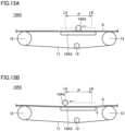
Figs. 13A and 13B are schematic diagrams each illustrating a configuration of a sheet conveyance device according to a third modification example. Referring to Figs. 13A and 13B, the following describes a textile-printing inkjet printer and a sheet conveyance device 10A3 included therein according to the third modification example that is based on the first embodiment.
-
As illustrated in Figs. 13A and 13B, a sheet conveyance device 10A3 according to the third modification example is different from the sheet conveyance device 10A according to the first embodiment in terms of a trajectory of a pressing roller 14A3 and a configuration of a contact portion 15A3.
-
The pressing roller 14A3 according to the third modification example is not moved in the direction away from the conveyance belt 11. That is, the pressing roller 14A3 is movable only along the direction substantially parallel to the conveyance direction in which the sheet S is conveyed by the conveyance belt 11.
-
The contact portion 15A3 according to the third modification example is movable along the normal direction of the rear surface 11b of the conveyance belt 11.
-
More specifically, the contact portion 15A3 is moved away from the conveyance belt 11 at a time point at which the pressing roller 14 has reached each of predetermined positions (see a position L5 and a position L6 in Figs. 13A and 13B) on the outbound path and the return path in the reciprocation direction. As the contact portion 15A3 is thus moved, the sandwiching of the sheet S by the pressing roller 14A3 and the contact portion 15A3 is released. Therefore, the pair of end portions of the adhesion region P are defined by the predetermined positions.
-
In the sheet conveyance device 10A3 configured as described above, when the pressing roller 14A3 passes through each of the pair of end portions of the adhesion region P in the reciprocation direction of the pressing roller 14A3, the pressing roller 14A3 passes through each of the pair of end portions at speed to leave the adhesion region P.
-
Also with such a configuration, an effect comparable to the effect described in the first embodiment can be obtained, with the result that stable conveyance of the sheet can be realized in each of the sheet conveyance device including the pressing roller reciprocated with respect to the conveyance direction of the sheet and the textile-printing inkjet printer including the sheet conveyance device.
-
Furthermore, with such a configuration, it is not necessary to move the pressing roller 14A3 in the direction away from the conveyance belt 11. Therefore, as compared with the sheet conveyance device 10A according to the first embodiment, it is possible to attain a reduced size of the device in the height direction, thereby reducing the manufacturing cost of the device.
-
Furthermore, with such a configuration, the above-described effect can be exhibited by moving the contact portion 15A3 that has been in contact with the rear surface 11b of the conveyance belt 11, the contact portion 15A3 being a member disposed at a position that cannot be reached by a hand of a user of the device. Therefore, in the sheet conveyance device 10A3, safety of the user is taken into consideration.
(Second Embodiment)
-
Figs. 14A and 14B are schematic diagrams each illustrating a configuration of a sheet conveyance device according to a second embodiment. Referring to Figs. 14A and 14B, the following describes a textile-printing inkjet printer and a sheet conveyance device 10B included therein according to the second embodiment. It should be noted that the operation of the sheet conveyance device 10B is basically the same as the operation of the sheet conveyance device 10A according to the first embodiment (see Fig. 4 and the like), and therefore will not be described repeatedly.
-
As illustrated in Figs. 14A and 14B, the sheet conveyance device 10B according to the present embodiment is different from the sheet conveyance device 10A according to the first embodiment in that a conveyance section 18 is included instead of the conveyance belt 11, the driving roller 12, the two driven rollers 13, and the contact portion 15. It should be noted that in the present embodiment, a separate-type sheet is used as the sheet S.
-
In the present embodiment, a conveyance drum having a substantially cylindrical shape is used as the conveyance section 18. The conveyance section 18 is driven to rotate around its axis by a rotational drive section such as a motor (not illustrated). An adhesive agent layer 17 is provided on a main surface 18a of the conveyance section 18. The material of the conveyance section 18 is not particularly limited, and various materials such as a metal, a rubber, and a resin can be used therefor. In the present embodiment, a conveyance section 18 composed of a metal is used.
-
The conveyance section 18 conveys the sheet S placed on the adhesive agent layer 17 in a predetermined conveyance direction (i.e., counterclockwise in Fig. 14B).
-
The pressing roller 14B is reciprocated in the forward direction and the reverse direction with respect to the conveyance direction in which the sheet S is conveyed by the conveyance section 18, so as to pass through the adhesion region P in which the sheet S placed on the adhesive agent layer 17 is adhered to the adhesive agent layer 17. In the adhesion region P, the pressing roller 14B and the conveyance section 18 sandwich the sheet S placed on the adhesive agent layer 17.
-
The pressing roller 14B is moved in the direction away from the conveyance section 18 at predetermined positions (see a position L7 and a position L8 in Figs. 14A and 14B) on each of the outbound path and the return path in the reciprocation direction. As the pressing roller 14B is thus moved, the sandwiching of the sheet S by the pressing roller 14B and the conveyance section 18 is released. Therefore, the pair of end portions of the adhesion region P are defined by the predetermined positions.
-
In the sheet conveyance device 10B configured as described above, when the pressing roller 14B passes through each of the pair of end portions of the adhesion region P in the reciprocation direction of the pressing roller 14B, the pressing roller 14B passes through each of the pair of end portions at speed to leave the adhesion region P.
-
Also with such a configuration, an effect comparable to the effect described in the first embodiment can be obtained, with the result that stable conveyance of the sheet can be realized in each of the sheet conveyance device including the pressing roller reciprocated in the conveyance direction of the sheet and the textile-printing inkjet printer including the sheet conveyance device.
-
It should be noted that in the sheet conveyance device 10B according to the present embodiment, it has been illustratively described that the sandwiching of the sheet S between the pressing roller 14B and the conveyance section 18 is released by the pressing roller 14B being moved in the direction away from the conveyance section 18 at each of the predetermined positions; however, the configuration for releasing the sandwiching of the sheet S by the pressing roller 14B and the conveyance section 18 is not limited thereto.
-
For example, the configuration employed in the sheet conveyance device 10A1 according to the first modification example that is based on the first embodiment may be applied to the sheet conveyance device 10B. In this case, the main surface 18a of the conveyance section 18 may include portions corresponding to the abutment surface 15a and the pair of retraction surfaces 15b of the contact portion 15A1 in the first modification example.
-
Further, the configuration employed in the sheet conveyance device 10A2 according to the second modification example that is based on the first embodiment may be applied to the sheet conveyance device 10B. In this case, the outer peripheral surface of the pressing roller 14B may be provided with a portion corresponding to the cutout portion 14a of the pressing roller 14A2 in the second modification example.
(Fourth Modification Example)
-
Figs. 15A and 15B are schematic diagrams each illustrating a configuration of a sheet conveyance device according to a fourth modification example. Referring to Figs. 15A and 15B, the following describes a textile-printing inkjet printer and a sheet conveyance device 10B1 included therein according to a fourth modification example that is based on the second embodiment.
-
As illustrated in Figs. 15A and 15B, the sheet conveyance device 10B1 according to the fourth modification example is different from the sheet conveyance device 10B according to the second embodiment in terms of a configuration of a conveyance section 18B1.
-
In the fourth modification example, a conveyance plate having a substantially flat-plate shape is used as the conveyance section 18B1. The conveyance section 18B1 is movable in a predetermined direction with the sheet S being placed on the adhesive agent layer 17 provided on the main surface 18a thereof. The pressing roller 14B1 is disposed to face the main surface 18a with the conveyance section 18B1 being disposed at a predetermined position.
-
Also with such a configuration, an effect comparable to the effect described in the second embodiment can be obtained, with the result that stable conveyance of the sheet can be realized in each of the sheet conveyance device including the pressing roller reciprocated with respect to the conveyance direction of the sheet and the textile-printing inkjet printer including the sheet conveyance device.
(Third Embodiment)
-
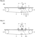
Fig. 16 is a schematic diagram illustrating a configuration of a sheet conveyance device according to a third embodiment. Referring to Fig. 16, the following describes a textile-printing inkjet printer and a sheet conveyance device 10C included therein according to a third embodiment. It should be noted that the operation of the sheet conveyance device 10C is basically the same as the operation of the sheet conveyance device 10A according to the first embodiment (see Fig. 4 and the like), and therefore will not be described repeatedly.
-
As illustrated in Fig. 16, the sheet conveyance device 10C according to the present embodiment is different from the sheet conveyance device 10A according to the first embodiment in terms of a trajectory of a pressing roller 14C and a configuration of a contact portion 15C.
-
The pressing roller 14C according to the present embodiment is not moved in a direction away from the conveyance belt 11. That is, the pressing roller 14C is movable only along the direction substantially parallel to the conveyance direction in which the sheet S is conveyed by the conveyance belt 11.
-
In the contact portion 15C according to the present embodiment, regions R1 of a portion of the contact portion 15C to sandwich the sheet S are each constituted of a soft portion that is softer than the other region R2 of the portion of the contact portion 15C to sandwich the sheet S. The soft portion is constituted of a member having a Shore hardness of 10 A or more and 50 A or less.
-
The regions R1 are provided in the contact portion 15C at portions corresponding to the pair of end portions of the adhesion region P. That is, the contact portion 15C is provided with the pair of regions R1. The region R2 is located between the pair of regions R1. It should be noted that in Fig. 16, each region R1 and the region R2 are provided with different markings for ease of understanding.
-
In the sheet conveyance device 10C thus configured, when the pressing roller 14C passes through each of the pair of end portions of the adhesion region P in the reciprocation direction of the pressing roller 14C, the sheet S placed on the adhesive agent layer 17 is sandwiched between the pressing roller 14C and the contact portion 15C with the sheet S being in abutment with the soft portion.
-
With the above-described configuration, stable conveyance of the sheet S can be realized in each of the sheet conveyance device 10C including the pressing roller 14C reciprocated with respect to the conveyance direction of the sheet S and the textile-printing inkjet printer including the sheet conveyance device 10C.
-
That is, the pressing roller is temporarily stopped with the pressing roller being pressed against the sheet at each of the both ends of the trajectory of the reciprocation. If no measure is taken for this, the portion of the sheet pressed by the stopped pressing roller is more firmly adhered to the adhesive agent layer than the other portion of the sheet. As a result, unevenness occurs in the strength of adhesion of the sheet to the adhesive agent layer.
-
Regarding this point, in the sheet conveyance device 10C according to the present embodiment, when the pressing roller 14C passes through each of the pair of end portions of the adhesion region P, the sheet S is sandwiched between the pressing roller 14C and the contact portion 15C with the sheet S being in abutment with the soft portion (i.e., the region R1) as described above.
-
With such a configuration, pressing force applied to the sheet S by the pressing roller 14C and the contact portion 15C at each of the both ends on the trajectory on which the pressing roller 14C is reciprocated can be reduced as compared with pressing force applied to the sheet S by the pressing roller 14C and the contact portion 15C at the other portion on the trajectory. Therefore, it is possible to effectively suppress occurrence of unevenness in the strength of adhesion of the sheet S to the adhesive agent layer 17.
-
Therefore, also with such a configuration, an effect comparable to the effect described in the first embodiment can be obtained, with the result that stable conveyance of the sheet can be realized in each of the sheet conveyance device including the pressing roller reciprocated with respect to the conveyance direction of the sheet and the textile-printing inkjet printer including the sheet conveyance device.
-
Further, with such a configuration, it is not necessary to move the pressing roller 14C in the direction away from the conveyance belt 11. Therefore, as compared with the sheet conveyance device 10A according to the first embodiment, it is possible to attain a reduced size of the device in the height direction, thereby reducing the manufacturing cost of the device.
-
Further, with such a configuration, the pressing force applied to the sheet S by the pressing roller 14C and the contact portion 15C can be readily adjusted by appropriately changing the hardness of the soft portion of the contact portion 15C.
(Fifth Modification Example)
-
Fig. 17 is a schematic diagram illustrating a configuration of a sheet conveyance device according to a fifth modification example. Referring to Fig. 17, the following describes a textile-printing inkjet printer and a sheet conveyance device 10C1 included therein according to a fifth modification example that is based on the third embodiment.
-
As illustrated in Fig. 17, the sheet conveyance device 10C1 according to the fifth modification example is different from the sheet conveyance device 10C according to the third embodiment in terms of configurations of a pressing roller 14C1 and a contact portion 15C1.
-
In the fifth modification example, a region R3 of a portion of the pressing roller 14C1 to sandwich the sheet S is constituted of a soft portion that is softer than the other region R4 of the portion of the pressing roller 14C1 to sandwich the sheet S. The soft portion is constituted of a member having a Shore hardness of 10 A or more and 50 A or less.
-
As the pressing roller 14C1 is rotated, the region R3 faces the conveyance belt 11 at each of the pair of end portions of the adhesion region P. It should be noted that in Fig. 17, the region R3 and the region R4 are provided with different markings for ease of understanding.
-
On the other hand, the contact portion 15C1 is different from the contact portion 15C according to the third embodiment in that no soft portion is included.
-
Also with such a configuration, an effect comparable to the effect described in the third embodiment can be obtained, with the result that stable conveyance of the sheet can be realized in each of the sheet conveyance device including the pressing roller reciprocated with respect to the conveyance direction of the sheet and the textile-printing inkjet printer including the sheet conveyance device.
-
Also with such a configuration, pressing force applied to the sheet S by the pressing roller 14C1 and the contact portion 15C1 can be readily adjusted by appropriately changing the hardness of the soft portion of the pressing roller 14C1.
-
It should be noted that in the sheet conveyance device 10C1 according to the fifth modification example, it has been illustratively described that the contact portion 15C1 includes no soft portion; however, the contact portion 15C1 may include the soft portion as with the contact portion 15C according to the third embodiment.
(Fourth Embodiment)
-
Fig. 18 is a schematic diagram illustrating a configuration of a sheet conveyance device according to a fourth embodiment. Referring to Fig. 18, the following describes a textile-printing inkjet printer and a sheet conveyance device 10D included therein according to the fourth embodiment. It should be noted that the operation of the sheet conveyance device 10D is basically the same as the operation of the sheet conveyance device 10C according to the third embodiment, and therefore will not be described repeatedly.
-
As illustrated in Fig. 18, the sheet conveyance device 10D according to the present embodiment is different from the sheet conveyance device 10C according to the third embodiment in that a conveyance section 18D is included instead of the conveyance belt 11, the driving roller 12, the two driven rollers 13, and the contact portion 15C. It should be noted that a separate-type sheet is used as the sheet S in the present embodiment.
-
In the present embodiment, a conveyance drum having a substantially cylindrical shape is used as the conveyance section 18D. The configuration of the conveyance section 18D is basically the same as the configuration of the conveyance section 18 (see Figs. 14A and 14B) according to the second embodiment, and therefore portions having the same configurations will not be described repeatedly.
-
A region R5 of a portion of the conveyance section 18D to sandwich the sheet S is constituted of a soft portion that is softer than the other region R6 of the portion of the conveyance section 18D to sandwich the sheet S. The soft portion is constituted of a member having a Shore hardness of 10 A or more and 50 A or less.
-
The region R5 is provided in the conveyance section 18D at a portion corresponding to each of the pair of end portions of the adhesion region P. It should be noted that in Fig. 18, the region R5 and the region R6 are provided with different markings for ease of understanding.
-
In the sheet conveyance device 10D thus configured, when the pressing roller 14D passes through each of the pair of end portions of the adhesion region P in the reciprocation direction of the pressing roller 14D, the sheet S placed on the adhesive agent layer 17 is sandwiched between the pressing roller 14D and the conveyance section 18D with the sheet S being in abutment with the soft portion.
-
Also with such a configuration, an effect comparable to the effect described in the third embodiment can be obtained, with the result that stable conveyance of the sheet can be realized in each of the sheet conveyance device including the pressing roller reciprocated with respect to the conveyance direction of the sheet and the textile-printing inkjet printer including the sheet conveyance device.
-
It should be noted that in the sheet conveyance device 10D according to the present embodiment, it has been illustratively described that the conveyance drum is used as the conveyance section 18D; however, as the conveyance section 18D, a conveyance plate provided with a soft portion such as the conveyance section 18B1 according to the fourth modification example that is based on the second embodiment may be used.
-
Furthermore, in the sheet conveyance device 10D according to the present embodiment, it has been illustratively described that no soft portion is provided in the pressing roller 14D; however, a pressing roller 14D having a portion provided with a soft portion may be used. As the configuration of the pressing roller 14D in this case, for example, basically the same configuration as the configuration of the pressing roller 14C1 according to the fifth modification example that is based on the third embodiment can be employed.
(Fifth Embodiment)
-
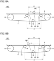
Figs. 19A and 19B are schematic diagrams each illustrating a configuration of a sheet conveyance device according to a fifth embodiment. Referring to Figs. 19A and 19B, the following describes a textile-printing inkjet printer and a sheet conveyance device 10E included therein according to the fifth embodiment. It should be noted that in Figs. 19A and 19B, a first point S1, a second point S2, and a third point S3, which will be described later, are illustrated as imaginary points (the same applies to Figs. 20A and 20B, which will be described later). Further, the operation of the sheet conveyance device 10E is basically the same as the operation of the sheet conveyance device 10A according to the first embodiment (see Fig. 4 and the like), and therefore will not be described repeatedly.
-
As illustrated in Figs. 19A and 19B, the sheet conveyance device 10E according to the present embodiment is firstly different from the sheet conveyance device 10A according to the first embodiment in terms of a trajectory of a pressing roller 14E and is secondly different therefrom in that a pair of contact rollers 19 are provided instead of the contact portion 15.
-
The pressing roller 14E is not moved in the direction away from the conveyance belt 11. That is, the pressing roller 14E is movable only along the direction substantially parallel to the conveyance direction in which the sheet S is conveyed by the conveyance belt 11.
-
The pair of contact rollers 19 are in contact with the rear surface 11b of the conveyance belt 11. The pair of contact rollers 19 are located at a distance therebetween in the conveyance direction in which the sheet S is conveyed by the conveyance belt 11.
-
More specifically, one of the pair of contact rollers 19 is located on an outer side with respect to one of the pair of end portions of the adhesion region P. Also, the other of the pair of contact rollers 19 is located on the outer side with respect to the other of the pair of end portions of the adhesion region P.
-
Each of the pair of contact rollers 19 is movable to change a distance d between the pair of contact rollers 19 in conjunction with the reciprocation of the pressing roller 14E. The following describes the operation of each of the pair of contact rollers 19 when one turning point and the other turning point on the trajectory of the reciprocation of the pressing roller 14E are respectively defined as the first point S1 and the second point S2 and a central point on the trajectory of the reciprocation of the pressing roller 14E is defined as the third point S3.
-
Each of the pair of contact rollers 19 is moved to decrease the distance d between the pair of contact rollers 19 as the pressing roller 14E is moved from the first point S1 toward the third point S3. Since the distance d is decreased, tension of the portion of the conveyance belt 11 between the pair of contact rollers 19 is increased.
-
Each of the pair of contact rollers 19 is moved to increase the distance d as the pressing roller 14E is moved from the third point S3 toward the second point S2 (see Fig. 19A). Since the distance d is increased, the tension of the portion of the conveyance belt 11 between the pair of contact rollers 19 is decreased.
-
Similarly, each of the pair of contact rollers 19 is moved to decrease the distance d as the pressing roller 14E is moved from the second point S2 toward the third point S3 (see Fig. 19B).
-
Each of the pair of contact rollers 19 is moved to increase the distance d as the pressing roller 14E is moved from the third point S3 toward the first point S1.
-
With such a configuration, the tension of the conveyance belt 11 when the pressing roller 14E is located at each of the both ends on the trajectory of the reciprocation can be smaller than the tension of the conveyance belt 11 when the pressing roller 14E is located at the other portion on the trajectory.
-
Therefore, pressing force applied to the sheet S by the pressing roller 14E when the pressing roller 14E is located at each of the both ends on the trajectory can be reduced as compared with pressing force applied to the sheet S by the pressing roller 14E when the pressing roller 14E is located at the other portion on the trajectory. As a result, it is possible to effectively suppress occurrence of unevenness in the strength of adhesion of the sheet S to the adhesive agent layer 17.
-
Therefore, also with such a configuration, an effect comparable to the effect described in the first embodiment can be obtained, with the result that stable conveyance of the sheet can be realized in each of the sheet conveyance device including the pressing roller reciprocated with respect to the conveyance direction of the sheet and the textile-printing inkjet printer including the sheet conveyance device.
-
Further, also with such a configuration, the tension of the conveyance belt 11 can be adjusted by appropriately changing the distance d between the pair of contact rollers 19, and therefore the pressing force applied to the sheet S by the pressing roller 14E can be adjusted.
(Sixth Modification Example)
-
Figs. 20A and 20B are schematic views each illustrating a configuration of a sheet conveyance device according to a sixth modification example that is based on the fifth embodiment. Referring to Figs. 20A and 20B, the following describes a textile-printing inkjet printer and a sheet conveyance device 10E1 included therein according to the sixth modification example.
-
As illustrated in Figs. 20A and 20B, the sheet conveyance device 10E1 according to the sixth modification example is different from the sheet conveyance device 10E according to the fifth embodiment only in terms of an operation of each of a pair of contact rollers 19E1.
-
More specifically, the pair of the contact rollers 19E1 are moved according to movement of a pressing roller 14E1 so as to sandwich the pressing roller 14E1 in the conveyance direction in which the sheet S is conveyed by the conveyance belt 11.
-
Each of the pair of contact rollers 19E1 is moved to decrease the distance d between the pair of contact rollers 19E1 as the pressing roller 14E1 is moved from the first point S1 toward the third point S3. Further, each of the pair of contact rollers 19E1 is moved to increase the distance d as pressing roller 14E1 is moved from the third point S3 toward the second point S2 (see Fig. 20A).
-
Similarly, each of the pair of contact rollers 19E1 is moved to decrease the distance d as the pressing roller 14E1 is moved from the second point S2 toward the third point S3. Further, each of the pair of contact rollers 19E1 is moved to increase the distance d as the pressing roller 14E1 is moved from the third point S3 toward the first point S1 (see Fig. 20B).
-
Also with such a configuration, the tension of the conveyance belt 11 when the pressing roller 14E1 is located at each of the both ends on the trajectory of the reciprocation can be smaller than the tension of the conveyance belt 11 when the pressing roller 14E1 is located at the central portion on the trajectory.
-
Also with such a configuration, an effect comparable to the effect described in the fifth embodiment can be obtained, with the result that stable conveyance of the sheet can be realized in each of the sheet conveyance device including the pressing roller reciprocated with respect to the conveyance direction of the sheet and the textile-printing inkjet printer including the sheet conveyance device.
-
Further, with such a configuration, the tension of the conveyance belt 11 can be adjusted by appropriately changing the distance d between the pair of contact rollers 19E1, and therefore the pressing force applied to the sheet S by the pressing roller 14E1 can be adjusted.
(Sixth Embodiment)
-
Fig. 21 is a schematic diagram illustrating a configuration of a sheet conveyance device according to a sixth embodiment. Referring to Fig. 21, the following describes a textile-printing inkjet printer and a sheet conveyance device 10F included therein according to the sixth embodiment. Further, the operation of the sheet conveyance device 10F is basically the same as the operation of the sheet conveyance device 10A according to the first embodiment (see Fig. 4 and the like), and therefore will not be described repeatedly.
-
As illustrated in Fig. 21, the sheet conveyance device 10F according to the sixth embodiment is different from the sheet conveyance device 10A according to the first embodiment in that a pair of contact rollers 19F are included instead of the contact portion 15.
-
The pair of contact rollers 19F are in contact with the rear surface 11b of the conveyance belt 11. The pair of contact rollers 19F are located at a distance therebetween in the conveyance direction in which the sheet S is conveyed by the conveyance belt 11.
-
More specifically, one of the pair of contact rollers 19F is located on the outer side with respect to one of the pair of end portions of the adhesion region P in the reciprocation direction of the pressing roller 14. The other of the pair of contact rollers 19F is located on the outer side with respect to the other of the pair of end portions of the adhesion region P. The pair of contact rollers 19F are fixed to be unmovable from the respective positions.
-
Also with such a configuration, an effect comparable to the effect described in the first embodiment can be obtained, with the result that stable conveyance of the sheet can be realized in each of the sheet conveyance device including the pressing roller reciprocated with respect to the conveyance direction of the sheet and the textile-printing inkjet printer including the sheet conveyance device.
(Seventh Embodiment)
-
Figs. 22A and 22B are schematic diagrams each illustrating a configuration of a sheet conveyance device according to a seventh embodiment. Referring to Figs. 22A and 22B, the following describes a textile-printing inkjet printer and a sheet conveyance device 10G included therein according to the seventh embodiment. Further, the operation of the sheet conveyance device 10G is basically the same as the operation of the sheet conveyance device 10A according to the first embodiment (see Fig. 4 and the like), and therefore will not be described repeatedly.
-
As illustrated in Figs. 22A and 22B, the sheet conveyance device 10G according to the seventh embodiment is different from the sheet conveyance device 10A according to the first embodiment in terms of a trajectory of a pressing roller 14G and is different therefrom in that a single contact roller 19G is included instead of the contact portion 15.
-
The pressing roller 14G is not moved in the direction away from the conveyance belt 11. That is, the pressing roller 14G is movable only along the direction substantially parallel to the conveyance direction in which the sheet S is conveyed by the conveyance belt 11.
-
The single contact roller 19G is in contact with the rear surface 11b of the conveyance belt 11 at a portion corresponding to a predetermined position between the both ends on the trajectory on which the pressing roller 14G is reciprocated. The single contact roller 19G is unmovable from the position in the conveyance direction. In the present embodiment, the single contact roller 19G is in contact with the rear surface 11b at a portion corresponding to the central portion on the trajectory.
-
In the present embodiment, the adhesion region P corresponds to a nip portion (see Fig. 22A) formed by the pressing roller 14G and the single contact roller 19G.
-
It should be noted that the adhering of the sheet S to the adhesive agent layer 17 by the pressing roller 14G being pressed against the sheet S is performed in a region corresponding to the trajectory of the reciprocation of the pressing roller 14G.
-
In the sheet conveyance device 10G configured as described above, when the pressing roller 14G passes through the adhesion region P in the reciprocation direction of the pressing roller 14G, the pressing roller 14G passes through the adhesion region P at speed to leave the adhesion region P.
-
Also with such a configuration, an effect comparable to the effect described in the first embodiment can be obtained, with the result that stable conveyance of the sheet can be realized in each of the sheet conveyance device including the pressing roller reciprocated with respect to the conveyance direction of the sheet and the textile-printing inkjet printer including the sheet conveyance device.
-
Further, with such a configuration, the tension of the conveyance belt 11 when the pressing roller 14G is located at each of the both ends on the trajectory of the reciprocation can be smaller than the tension of the conveyance belt 11 when the pressing roller 14G is located at other portion on the trajectory.
-
Therefore, pressing force applied to the sheet S by the pressing roller 14G when the pressing roller 14G is located at each of the both ends on the trajectory can be reduced as compared with pressing force applied to the sheet S by the pressing roller 14G at the position at which the pressing roller 14G and the single contact roller 19G form the nip portion. As a result, it is possible to effectively suppress occurrence of unevenness in the strength of adhesion of the sheet S to the adhesive agent layer 17.
(Supplementary Notes)
-
The characteristic configurations of the sheet conveyance device and the textile-printing inkjet printer as disclosed in the embodiments and the modification examples thereof are summarized as follows.
[Supplementary Note 1]
-
A sheet conveyance device comprising:
- a conveyance belt that has a front surface provided with an adhesive agent layer and a rear surface located opposite to the front surface and that conveys, in a predetermined conveyance direction, a sheet placed on the adhesive agent layer;
- a pressing roller disposed to face the front surface; and
- a contact portion in contact with the rear surface, wherein
- the pressing roller is reciprocated in a forward direction and a reverse direction with respect to the conveyance direction so as to pass through an adhesion region in which the sheet placed on the adhesive agent layer is adhered to the adhesive agent layer,
- in the adhesion region, the pressing roller and the contact portion sandwich the sheet placed on the adhesive agent layer and the conveyance belt, and
- when the pressing roller passes through each of a pair of end portions of the adhesion region in a reciprocation direction of the pressing roller, the pressing roller passes through each of the pair of end portions at speed to leave the adhesion region.
[Supplementary Note 2]
-
The sheet conveyance device according to supplementary note 1, wherein each of the pair of end portions of the adhesion region is defined by the pressing roller being moved in a direction away from the conveyance belt at a predetermined position on a corresponding one of an outbound path and a return path in the reciprocation direction.
[Supplementary Note 3]
-
The sheet conveyance device according to supplementary note 1, wherein
- the contact portion includes an abutment surface in abutment with the conveyance belt and a pair of retraction surfaces that sandwich the abutment surface in the conveyance direction and that are each located at a distance from the conveyance belt, and
- each of the pair of end portions of the adhesion region is defined by a boundary portion between the abutment surface and a corresponding one of the pair of retraction surfaces.
[Supplementary Note 4]
-
The sheet conveyance device according to supplementary note 1, wherein
- a cutout portion is provided in an outer peripheral surface of the pressing roller, and
- each of the pair of end portions of the adhesion region is defined by the cutout portion facing the conveyance belt at a predetermined position on a corresponding one of an outbound path and a return path in the reciprocation direction as the pressing roller is rotated.
[Supplementary Note 5]
-
The sheet conveyance device according to supplementary note 1, wherein
- the contact portion is movable along a normal direction of the rear surface, and
- each of the pair of end portions of the adhesion region is defined by the contact portion being moved away from the conveyance belt at a time point at which the pressing roller has reached a predetermined position on a corresponding one of an outbound path and a return path in the reciprocation direction.
[Supplementary Note 6]
-
A sheet conveyance device comprising:
- a conveyance section that has a main surface provided with an adhesive agent layer and that conveys, in a predetermined conveyance direction, a sheet placed on the adhesive agent layer; and
- a pressing roller disposed to face the main surface, wherein
- the pressing roller is reciprocated in a forward direction and a reverse direction with respect to the conveyance direction so as to pass through an adhesion region in which the sheet placed on the adhesive agent layer is adhered to the adhesive agent layer,
- in the adhesion region, the pressing roller and the conveyance section sandwich the sheet placed on the adhesive agent layer, and
- when the pressing roller passes through each of a pair of end portions of the adhesion region in a reciprocation direction of the pressing roller, the pressing roller passes through each of the pair of end portions at speed to leave the adhesion region.
[Supplementary Note 7]
-
The sheet conveyance device according to supplementary note 6, wherein each of the pair of end portions of the adhesion region is defined by the pressing roller being moved in a direction away from the conveyance section at a predetermined position on a corresponding one of an outbound path and a return path in the reciprocation direction.
[Supplementary Note 8]
-
The sheet conveyance device according to supplementary note 6, wherein
- the main surface includes a first region in which a portion of the adhesive agent layer on which the sheet is placed is provided, and a pair of second regions that sandwich the first region in the conveyance direction and that are located to be retracted with respect to the first region, and
- each of the pair of end portions of the adhesion region is defined by a boundary portion between the first region and a corresponding one of the pair of second regions.
[Supplementary Note 9]
-
The sheet conveyance device according to supplementary note 6, wherein
- a cutout portion is provided in an outer peripheral surface of the pressing roller, and
- each of the pair of end portions of the adhesion region is defined by the cutout portion facing the conveyance section at a predetermined position on a corresponding one of an outbound path and a return path in the reciprocation direction as the pressing roller is rotated.
[Supplementary Note 10]
-
The sheet conveyance device according to any one of supplementary notes 6 to 9, wherein the conveyance section is constituted of one of a conveyance plate and a conveyance drum.
[Supplementary Note 11]
-
A sheet conveyance device comprising:
- a conveyance belt that has a front surface provided with an adhesive agent layer and a rear surface located opposite to the front surface and that conveys, in a predetermined conveyance direction, a sheet placed on the adhesive agent layer;
- a pressing roller disposed to face the front surface; and
- a contact portion in contact with the rear surface, wherein
- the pressing roller is reciprocated in a forward direction and a reverse direction with respect to the conveyance direction in an adhesion region in which the sheet placed on the adhesive agent layer is adhered to the adhesive agent layer,
- in the adhesion region, the pressing roller and the contact portion sandwich the sheet placed on the adhesive agent layer and the conveyance belt,
- a region of a portion of at least one of the pressing roller and the contact portion to sandwich the sheet is constituted of a soft portion that is softer than another region of the portion to sandwich the sheet, and
- when the pressing roller passes through each of a pair of end portions of the adhesion region in a reciprocation direction of the pressing roller, the sheet placed on the adhesive agent layer is sandwiched between the pressing roller and the contact portion with the sheet being in abutment with the soft portion.
[Supplementary Note 12]
-
The sheet conveyance device according to supplementary note 11, wherein
- the soft portion is provided in the contact portion, and
- the soft portion is constituted of a member having a Shore hardness of 10 A or more and 50 A or less.
[Supplementary Note 13]
-
The sheet conveyance device according to supplementary note 11, wherein
- the soft portion is provided in the pressing roller, and
- the soft portion is constituted of a member having a Shore hardness of 10 A or more and 50 A or less.
[Supplementary Note 14]
-
A sheet conveyance device comprising:
- a conveyance section that has a main surface provided with an adhesive agent layer and that conveys, in a predetermined conveyance direction, a sheet placed on the adhesive agent layer; and
- a pressing roller disposed to face the main surface, wherein
- the pressing roller is reciprocated in a forward direction and a reverse direction with respect to the conveyance direction in an adhesion region in which the sheet placed on the adhesive agent layer is adhered to the adhesive agent layer,
- in the adhesion region, the pressing roller and the conveyance section sandwich the sheet placed on the adhesive agent layer,
- a region of a portion of at least one of the pressing roller and the conveyance section to sandwich the sheet is constituted of a soft portion that is softer than another region of the portion to sandwich the sheet, and
- when the pressing roller passes through each of a pair of end portions of the adhesion region in a reciprocation direction of the pressing roller, the sheet placed on the adhesive agent layer is sandwiched between the pressing roller and the conveyance section with the sheet being in abutment with the soft portion.
[Supplementary Note 15]
-
The sheet conveyance device according to supplementary note 14, wherein
- the soft portion is provided in the conveyance section, and
- the soft portion is constituted of a member having a Shore hardness of 10 A or more and 50 A or less.
[Supplementary Note 16]
-
The sheet conveyance device according to supplementary note 14, wherein
- the soft portion is provided in the pressing roller, and
- the soft portion is constituted of a member having a Shore hardness of 10 A or more and 50 A or less.
[Supplementary Note 17]
-
The sheet conveyance device according to any one of supplementary notes 14 to 16, wherein the conveyance section is constituted of one of a conveyance plate and a conveyance drum.
[Supplementary Note 18]
-
A sheet conveyance device comprising:
- a conveyance belt that has a front surface provided with an adhesive agent layer and a rear surface located opposite to the front surface and that conveys, in a predetermined conveyance direction, a sheet placed on the adhesive agent layer;
- a pressing roller disposed to face the front surface; and
- a pair of contact rollers in contact with the rear surface, wherein
- the pair of contact rollers are located at a distance between the pair of contact rollers in the conveyance direction,
- the pressing roller is reciprocated in a forward direction and a reverse direction with respect to the conveyance direction in an adhesion region in which the sheet placed on the adhesive agent layer is adhered to the adhesive agent layer,
- in the adhesion region, the pressing roller is pressed against the sheet placed on the adhesive agent layer,
- each of the pair of contact rollers is movable to change the distance between the pair of contact rollers in conjunction with reciprocation of the pressing roller,
- when one turning point and the other turning point on a trajectory of the reciprocation of the pressing roller are respectively defined as a first point and a second point and a central point on the trajectory of the reciprocation of the pressing roller is defined as a third point, each of the pair of contact rollers is moved to decrease the distance between the pair of contact rollers as the pressing roller is moved from the first point toward the third point and is moved from the second point toward the third point, and each of the pair of contact rollers is moved to increase the distance between the pair of contact rollers as the pressing roller is moved from the third point toward the first point and is moved from the third point to the second point.
[Supplementary Note 19]
-
A sheet conveyance device comprising:
- a conveyance belt that has a front surface provided with an adhesive agent layer and a rear surface located opposite to the front surface and that conveys, in a predetermined conveyance direction, a sheet placed on the adhesive agent layer;
- a pressing roller disposed to face the front surface; and
- a pair of contact rollers in contact with the rear surface, wherein
- the pair of contact rollers are located at a distance between the pair of contact rollers in the conveyance direction,
- the pressing roller is reciprocated in a forward direction and a reverse direction with respect to the conveyance direction in an adhesion region in which the sheet placed on the adhesive agent layer is adhered to the adhesive agent layer,
- one of the pair of contact rollers is located on an outer side with respect to one of a pair of end portions of the adhesion region in a reciprocation direction of the pressing roller, and the other of the pair of contact rollers is located on the outer side with respect to the other of the pair of end portions of the adhesion region,
- the pair of contact rollers are unmovable in the conveyance direction,
- in the adhesion region, the pressing roller is pressed against the sheet placed on the adhesive agent layer,
- each of the pair of end portions of the adhesion region is defined by the pressing roller being moved in a direction away from the conveyance belt at a predetermined position on a corresponding one of an outbound path and a return path in the reciprocation direction, and
- when the pressing roller passes through each of the pair of end portions of the adhesion region in the reciprocation direction, the pressing roller passes through each of the pair of end portions at speed to leave the adhesion region.
[Supplementary Note 20]
-
A sheet conveyance device comprising:
- a conveyance belt that has a front surface provided with an adhesive agent layer and a rear surface located opposite to the front surface and that conveys, in a predetermined conveyance direction, a sheet placed on the adhesive agent layer;
- a pressing roller disposed to face the front surface; and
- a single contact roller in contact with the rear surface, wherein
- the pressing roller is reciprocated in a forward direction and a reverse direction with respect to the conveyance direction so as to pass through an adhesion region in which the sheet placed on the adhesive agent layer is adhered to the adhesive agent layer,
- the single contact roller is unmovable in the conveyance direction,
- in the adhesion region, the pressing roller and the contact roller sandwich the sheet placed on the adhesive agent layer and the conveyance belt, and
- when the pressing roller passes through the adhesion region in a reciprocation direction of the pressing roller, the pressing roller passes through the adhesion region at speed to leave the adhesion region.
[Supplementary Note 21]
-
A textile-printing inkjet printer comprising:
- the sheet conveyance device according to any one of supplementary notes 1 to 20; and
- an inkjet head that ejects ink onto a sheet.
(Other Embodiments, etc.)
-
In each of the embodiment of the present invention and the modification examples thereof, it has been illustratively described that the sheet conveyance device is used in the textile-printing inkjet printer; however, the sheet conveyance device is not particularly limited to the one used in the textile-printing inkjet printer.
-
Furthermore, various changes can be made in the shape, configuration, size, number, material and the like of each of the portions illustrated in the embodiments of the present invention and the modification examples thereof without departing from the gist of the present invention.
-
Furthermore, the characteristic configurations described in the embodiments of the present invention and the modification examples thereof can be surely combined without departing from the gist of the present invention.
-
Although the embodiments of the present invention have been described and illustrated in detail, it is clearly understood that the same is by way of illustration and example only and is not to be taken by way of limitation. The scope of the present invention is defined by the terms of the claims, and is intended to include any modifications within the scope and meaning equivalent to the terms of the claims.