EP4442303A2 - Respiratory support system and blower for respiratory support system - Google Patents
Respiratory support system and blower for respiratory support system Download PDFInfo
- Publication number
- EP4442303A2 EP4442303A2 EP24195504.6A EP24195504A EP4442303A2 EP 4442303 A2 EP4442303 A2 EP 4442303A2 EP 24195504 A EP24195504 A EP 24195504A EP 4442303 A2 EP4442303 A2 EP 4442303A2
- Authority
- EP
- European Patent Office
- Prior art keywords
- impeller
- flow
- outlet
- blower
- gases
- Prior art date
- Legal status (The legal status is an assumption and is not a legal conclusion. Google has not performed a legal analysis and makes no representation as to the accuracy of the status listed.)
- Granted
Links
Images











Classifications
-
- A—HUMAN NECESSITIES
- A61—MEDICAL OR VETERINARY SCIENCE; HYGIENE
- A61M—DEVICES FOR INTRODUCING MEDIA INTO, OR ONTO, THE BODY; DEVICES FOR TRANSDUCING BODY MEDIA OR FOR TAKING MEDIA FROM THE BODY; DEVICES FOR PRODUCING OR ENDING SLEEP OR STUPOR
- A61M16/00—Devices for influencing the respiratory system of patients by gas treatment, e.g. ventilators; Tracheal tubes
- A61M16/0057—Pumps therefor
- A61M16/0066—Blowers or centrifugal pumps
-
- A—HUMAN NECESSITIES
- A61—MEDICAL OR VETERINARY SCIENCE; HYGIENE
- A61M—DEVICES FOR INTRODUCING MEDIA INTO, OR ONTO, THE BODY; DEVICES FOR TRANSDUCING BODY MEDIA OR FOR TAKING MEDIA FROM THE BODY; DEVICES FOR PRODUCING OR ENDING SLEEP OR STUPOR
- A61M16/00—Devices for influencing the respiratory system of patients by gas treatment, e.g. ventilators; Tracheal tubes
- A61M16/0057—Pumps therefor
- A61M16/0066—Blowers or centrifugal pumps
- A61M16/0069—Blowers or centrifugal pumps the speed thereof being controlled by respiratory parameters, e.g. by inhalation
-
- A—HUMAN NECESSITIES
- A61—MEDICAL OR VETERINARY SCIENCE; HYGIENE
- A61M—DEVICES FOR INTRODUCING MEDIA INTO, OR ONTO, THE BODY; DEVICES FOR TRANSDUCING BODY MEDIA OR FOR TAKING MEDIA FROM THE BODY; DEVICES FOR PRODUCING OR ENDING SLEEP OR STUPOR
- A61M16/00—Devices for influencing the respiratory system of patients by gas treatment, e.g. ventilators; Tracheal tubes
- A61M16/021—Devices for influencing the respiratory system of patients by gas treatment, e.g. ventilators; Tracheal tubes operated by electrical means
- A61M16/022—Control means therefor
-
- A—HUMAN NECESSITIES
- A61—MEDICAL OR VETERINARY SCIENCE; HYGIENE
- A61M—DEVICES FOR INTRODUCING MEDIA INTO, OR ONTO, THE BODY; DEVICES FOR TRANSDUCING BODY MEDIA OR FOR TAKING MEDIA FROM THE BODY; DEVICES FOR PRODUCING OR ENDING SLEEP OR STUPOR
- A61M16/00—Devices for influencing the respiratory system of patients by gas treatment, e.g. ventilators; Tracheal tubes
- A61M16/021—Devices for influencing the respiratory system of patients by gas treatment, e.g. ventilators; Tracheal tubes operated by electrical means
- A61M16/022—Control means therefor
- A61M16/024—Control means therefor including calculation means, e.g. using a processor
-
- A—HUMAN NECESSITIES
- A61—MEDICAL OR VETERINARY SCIENCE; HYGIENE
- A61M—DEVICES FOR INTRODUCING MEDIA INTO, OR ONTO, THE BODY; DEVICES FOR TRANSDUCING BODY MEDIA OR FOR TAKING MEDIA FROM THE BODY; DEVICES FOR PRODUCING OR ENDING SLEEP OR STUPOR
- A61M16/00—Devices for influencing the respiratory system of patients by gas treatment, e.g. ventilators; Tracheal tubes
- A61M16/06—Respiratory or anaesthetic masks
- A61M16/0666—Nasal cannulas or tubing
-
- A—HUMAN NECESSITIES
- A61—MEDICAL OR VETERINARY SCIENCE; HYGIENE
- A61M—DEVICES FOR INTRODUCING MEDIA INTO, OR ONTO, THE BODY; DEVICES FOR TRANSDUCING BODY MEDIA OR FOR TAKING MEDIA FROM THE BODY; DEVICES FOR PRODUCING OR ENDING SLEEP OR STUPOR
- A61M16/00—Devices for influencing the respiratory system of patients by gas treatment, e.g. ventilators; Tracheal tubes
- A61M16/10—Preparation of respiratory gases or vapours
- A61M16/1075—Preparation of respiratory gases or vapours by influencing the temperature
- A61M16/109—Preparation of respiratory gases or vapours by influencing the temperature the humidifying liquid or the beneficial agent
-
- A—HUMAN NECESSITIES
- A61—MEDICAL OR VETERINARY SCIENCE; HYGIENE
- A61M—DEVICES FOR INTRODUCING MEDIA INTO, OR ONTO, THE BODY; DEVICES FOR TRANSDUCING BODY MEDIA OR FOR TAKING MEDIA FROM THE BODY; DEVICES FOR PRODUCING OR ENDING SLEEP OR STUPOR
- A61M16/00—Devices for influencing the respiratory system of patients by gas treatment, e.g. ventilators; Tracheal tubes
- A61M16/10—Preparation of respiratory gases or vapours
- A61M16/14—Preparation of respiratory gases or vapours by mixing different fluids, one of them being in a liquid phase
- A61M16/16—Devices to humidify the respiration air
-
- F—MECHANICAL ENGINEERING; LIGHTING; HEATING; WEAPONS; BLASTING
- F04—POSITIVE - DISPLACEMENT MACHINES FOR LIQUIDS; PUMPS FOR LIQUIDS OR ELASTIC FLUIDS
- F04D—NON-POSITIVE-DISPLACEMENT PUMPS
- F04D17/00—Radial-flow pumps, e.g. centrifugal pumps; Helico-centrifugal pumps
- F04D17/08—Centrifugal pumps
- F04D17/16—Centrifugal pumps for displacing without appreciable compression
-
- F—MECHANICAL ENGINEERING; LIGHTING; HEATING; WEAPONS; BLASTING
- F04—POSITIVE - DISPLACEMENT MACHINES FOR LIQUIDS; PUMPS FOR LIQUIDS OR ELASTIC FLUIDS
- F04D—NON-POSITIVE-DISPLACEMENT PUMPS
- F04D27/00—Control, e.g. regulation, of pumps, pumping installations or pumping systems specially adapted for elastic fluids
- F04D27/001—Testing thereof; Determination or simulation of flow characteristics; Stall or surge detection, e.g. condition monitoring
-
- F—MECHANICAL ENGINEERING; LIGHTING; HEATING; WEAPONS; BLASTING
- F04—POSITIVE - DISPLACEMENT MACHINES FOR LIQUIDS; PUMPS FOR LIQUIDS OR ELASTIC FLUIDS
- F04D—NON-POSITIVE-DISPLACEMENT PUMPS
- F04D29/00—Details, component parts, or accessories
- F04D29/40—Casings; Connections of working fluid
- F04D29/42—Casings; Connections of working fluid for radial or helico-centrifugal pumps
- F04D29/4206—Casings; Connections of working fluid for radial or helico-centrifugal pumps especially adapted for elastic fluid pumps
- F04D29/4226—Fan casings
- F04D29/4246—Fan casings comprising more than one outlet
-
- A—HUMAN NECESSITIES
- A61—MEDICAL OR VETERINARY SCIENCE; HYGIENE
- A61M—DEVICES FOR INTRODUCING MEDIA INTO, OR ONTO, THE BODY; DEVICES FOR TRANSDUCING BODY MEDIA OR FOR TAKING MEDIA FROM THE BODY; DEVICES FOR PRODUCING OR ENDING SLEEP OR STUPOR
- A61M16/00—Devices for influencing the respiratory system of patients by gas treatment, e.g. ventilators; Tracheal tubes
- A61M16/0003—Accessories therefor, e.g. sensors, vibrators, negative pressure
- A61M2016/0027—Accessories therefor, e.g. sensors, vibrators, negative pressure pressure meter
-
- A—HUMAN NECESSITIES
- A61—MEDICAL OR VETERINARY SCIENCE; HYGIENE
- A61M—DEVICES FOR INTRODUCING MEDIA INTO, OR ONTO, THE BODY; DEVICES FOR TRANSDUCING BODY MEDIA OR FOR TAKING MEDIA FROM THE BODY; DEVICES FOR PRODUCING OR ENDING SLEEP OR STUPOR
- A61M16/00—Devices for influencing the respiratory system of patients by gas treatment, e.g. ventilators; Tracheal tubes
- A61M16/0003—Accessories therefor, e.g. sensors, vibrators, negative pressure
- A61M2016/003—Accessories therefor, e.g. sensors, vibrators, negative pressure with a flowmeter
- A61M2016/0033—Accessories therefor, e.g. sensors, vibrators, negative pressure with a flowmeter electrical
- A61M2016/0036—Accessories therefor, e.g. sensors, vibrators, negative pressure with a flowmeter electrical in the breathing tube and used in both inspiratory and expiratory phase
-
- A—HUMAN NECESSITIES
- A61—MEDICAL OR VETERINARY SCIENCE; HYGIENE
- A61M—DEVICES FOR INTRODUCING MEDIA INTO, OR ONTO, THE BODY; DEVICES FOR TRANSDUCING BODY MEDIA OR FOR TAKING MEDIA FROM THE BODY; DEVICES FOR PRODUCING OR ENDING SLEEP OR STUPOR
- A61M16/00—Devices for influencing the respiratory system of patients by gas treatment, e.g. ventilators; Tracheal tubes
- A61M16/0003—Accessories therefor, e.g. sensors, vibrators, negative pressure
- A61M2016/003—Accessories therefor, e.g. sensors, vibrators, negative pressure with a flowmeter
- A61M2016/0033—Accessories therefor, e.g. sensors, vibrators, negative pressure with a flowmeter electrical
- A61M2016/0039—Accessories therefor, e.g. sensors, vibrators, negative pressure with a flowmeter electrical in the inspiratory circuit
-
- A—HUMAN NECESSITIES
- A61—MEDICAL OR VETERINARY SCIENCE; HYGIENE
- A61M—DEVICES FOR INTRODUCING MEDIA INTO, OR ONTO, THE BODY; DEVICES FOR TRANSDUCING BODY MEDIA OR FOR TAKING MEDIA FROM THE BODY; DEVICES FOR PRODUCING OR ENDING SLEEP OR STUPOR
- A61M2205/00—General characteristics of the apparatus
- A61M2205/15—Detection of leaks
-
- A—HUMAN NECESSITIES
- A61—MEDICAL OR VETERINARY SCIENCE; HYGIENE
- A61M—DEVICES FOR INTRODUCING MEDIA INTO, OR ONTO, THE BODY; DEVICES FOR TRANSDUCING BODY MEDIA OR FOR TAKING MEDIA FROM THE BODY; DEVICES FOR PRODUCING OR ENDING SLEEP OR STUPOR
- A61M2205/00—General characteristics of the apparatus
- A61M2205/33—Controlling, regulating or measuring
- A61M2205/3365—Rotational speed
-
- A—HUMAN NECESSITIES
- A61—MEDICAL OR VETERINARY SCIENCE; HYGIENE
- A61M—DEVICES FOR INTRODUCING MEDIA INTO, OR ONTO, THE BODY; DEVICES FOR TRANSDUCING BODY MEDIA OR FOR TAKING MEDIA FROM THE BODY; DEVICES FOR PRODUCING OR ENDING SLEEP OR STUPOR
- A61M2230/00—Measuring parameters of the user
- A61M2230/40—Respiratory characteristics
- A61M2230/46—Resistance or compliance of the lungs
Definitions
- the present disclosure relates to a respiratory support system comprising a blower for providing a flow of respiratory gases to a patient or user, and a blower for a respiratory support system.
- a blower gases supply unit
- continuous positive airway pressure devices and/or systems for treating sleep apnea comprise a blower for providing a flow of positive pressure air to support a user's airways.
- a blower is used together with a humidifier to provide a flow of humidified gases to a user.
- a respiratory system may include an integrated gases supply device which comprises both a humidifier and a blower.
- a prior art integrated gases supply device is described in international patent publication WO2013/009193 .
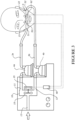
- FIG. 1 A schematic representation of a modular respiratory system is provided in Figure 1 .
- the system comprises a blower 2 in fluid communication with a humidifier 4 via a conduit.
- a further conduit 3 provides a flow of gases generated by blower 2 and humidified by the humidifier to a user 1 via a patient interface 5.
- a further schematic representation is provided in Figure 2 , representing an integrated blower and humidification unit 6 that comprises a blower 2 and humidifier 4 in a single integrated unit.
- the patient interface 5 may be a full face mask that provides a flow of gases to the user's airways via the user's mouth and nose, or may be an oral interface or a nasal interface.
- a nasal interface may seal against the users face around the nose, or may engage with the user's nares, in either a sealing or non-sealing way.
- a nasal cannula may provide a pair of prongs to engage with the user's nares without forming an air tight seal.
- a nasal interface may comprise a pair of nasal pillows that sealingly engage the nares of a user.
- a blower for providing a flow or respiratory gases comprises a respiratory (support) system comprising a dual outlet blower, wherein one of a first and a second outlet of the blower provides a flow of gases to one of a pair of nasal outlets of a nasal interface and the other one of the first and second outlets provides a flow of gases to the other one of the pair of nasal outlets of the nasal interface, or wherein one of the first and second outlets provides a flow of gases to a nasal outlet of a oro-nasal interface and the other one of the first and second outlets provides a flow of gases to an oral outlet of the oro-nasal interface.
- the blower comprises:
- a flow of gases from the first outlet is greater than a flow of gases from the second outlet
- a flow of gases from the second outlet is greater than a flow of gases from the first outlet
- rotation of the impeller in a first direction of rotation generates a first flow of gases from the first outlet and a second flow of gases from the second outlet
- the flowrate of the first flow of gases is substantially the same as the flowrate of the third flow of gases.
- the blower comprises a motor for driving rotation of the impeller
- the housing comprises the impeller chamber and a motor chamber for supporting the motor within the housing.
- the blower comprises a first impeller and a second impeller
- the housing comprises a first impeller chamber in which the first impeller rotates and a second impeller chamber in which the second impeller rotates, and wherein the first and second impellers are rotationally coupled to rotate together, the first impeller for generating a flow of gases from the first outlet when the first and second impellers rotate in the first direction of rotation, and the second impeller for generating a flow of gases from the second outlet when the first and second impellers rotate in the second direction of rotation.
- the blower comprises a motor for driving rotation of the first and second impellers, the motor comprising a rotor and a stator, wherein the first and second impellers are rotationally coupled to the rotor.
- the rotor is positioned axially between the first and second impellers, and wherein the housing comprises a motor chamber for the motor located axially between the first and second impeller chambers.
- the impeller is a centrifugal impeller.
- the housing comprises a volute chamber receiving a flow of gases from the impeller chamber.
- the first outlet extends substantially tangentially from the housing with respect to a first direction of rotation of the impeller
- the second outlet extends substantially tangentially from the housing with respect to an opposite second direction of rotation of the impeller.
- the volute chamber receives a flow of gases from the first and second impeller chambers.
- the housing comprises:
- the first and second outlets are axial outlets
- the first outlet is an axial outlet at a first side of the blower and the second outlet is an axial outlet at a second side of the blower.
- the housing comprises a first stator ring and a second stator ring, each stator ring comprising a plurality of volute paths, the first axial outlet comprising the volute paths of the first stator ring, and the second axial outlet comprising the volute paths of the second stator ring.
- each stator ring comprises a plurality of curved vanes, each said volute path separated from an adjacent volute path in the stator ring by a said curved vane.
- each stator ring comprises the plurality of curved vanes spaced circumferentially apart radially outside of or adjacent to or at the radial outer perimeter of the impeller or a respective one of a first impeller and a second impeller.
- the blower comprises:
- the blower comprises:
- the system comprises the nasal interface, the interface comprising a first nasal outlet for providing a flow of respiratory gases to a user via one of the user's nares, and a second nasal outlet for providing a flow of respiratory gases to the user via the other one of the user's nares, wherein the first outlet of the blower is in fluid communication with the first nasal outlet of the nasal interface, and the second outlet of the blower is in fluid communication with the second nasal outlet of the nasal interface, wherein rotation of an impeller of the blower in a first direction of rotation generates a flow of gases to the first nasal outlet of the nasal interface, and rotation of the impeller in a second direction of rotation generates a flow of gases to the second nasal outlet of the nasal interface.
- the system comprises a sensing arrangement to determine occlusion of one of the nares of the user and a controller to control the direction of rotation of the impeller in response, wherein if the sensing arrangement detects one of the user's nares is at least partially occluded, the sensing arrangement causes the impeller to rotate in one of the first and second directions of rotation to generate a flow to the other one of the user's nares, and vice versa.
- the sensing arrangement comprises a pressure or flow sensor to detect a pressure or flow to or at the user's nares to determine if one or other of the user's nares is at least partially occluded.
- the sensing arrangement comprises:
- the system comprises the oro-nasal interface comprising the nasal outlet for providing a flow of respiratory gases to a user via at least one of the user's nares, and the oral outlet for providing a flow of respiratory gases to the user via the user's mouth, and
- the system comprises a controller configured to control the direction of rotation of the impeller based on at least one of a user input, a measured condition, or a predetermined condition.
- a dual axial outlet blower comprises:
- rotation of the impeller in a first direction of rotation generates a first flow of gases from the first outlet and a second flow of gases from the second outlet
- the blower comprises a motor for driving rotation of the impeller
- the housing comprises the impeller chamber and a motor chamber for supporting the motor within the housing.
- the impeller is a centrifugal impeller.
- the first outlet is an axial outlet at a first side of the blower and the second outlet is an axial outlet at a second side of the blower.
- the blower comprises a first impeller and a second impeller
- the housing comprises a first impeller chamber in which the first impeller rotates and a second impeller chamber in which the second impeller rotates, and wherein the first and second impellers are rotationally coupled to rotate together, the first impeller generating a flow of gases from the first outlet when the first and second impellers rotate in the first direction of rotation, and the second impeller generating a flow of gases from the second outlet when the first and second impellers rotate in the second direction of rotation.
- the blower comprises a motor for driving rotation of the first and second impellers, the motor comprising a rotor and a stator, wherein the first and second impellers are rotationally coupled to the rotor.
- the rotor is positioned axially between the first and second impellers, and wherein the housing comprises a motor chamber for the motor located axially between the first and second impeller chambers.
- the housing comprises a first stator ring and a second stator ring, each stator ring comprising a plurality of volute paths, the first axial outlet comprising the volute paths of the first stator ring, and the second axial outlet comprising the volute paths of the second stator ring.
- the blower is without a volute chamber other than the volute paths of the stator rings.
- each stator ring comprises a plurality of curved vanes, each said volute path separated from an adjacent volute path in the stator ring by a said curved vane.
- each stator ring comprises the plurality of curved vanes spaced circumferentially apart radially outside of or adjacent to or at the radial outer perimeter of the impeller or a respective one of a first impeller and a second impeller.
- a dual axial outlet blower comprises:
- the impeller is a centrifugal impeller.
- the first outlet is an axial outlet at a first side of the blower and the second outlet is an axial outlet at a second side of the blower.
- the blower comprises a first impeller and a second impeller
- the housing comprises a first impeller chamber in which the first impeller rotates and a second impeller chamber in which the second impeller rotates, and wherein the first and second impellers are rotationally coupled to rotate together, the first impeller generating a flow of gases from the first outlet when the first and second impellers rotate in the first direction of rotation, and the second impeller generating a flow of gases from the second outlet when the first and second impellers rotate in the second direction of rotation.
- the housing comprises a first stator ring and a second stator ring, each stator ring comprising a plurality of volute paths, the first axial outlet comprising the volute paths of the first stator ring, and the second axial outlet comprising the volute paths of the second stator ring.
- the blower is without a volute chamber other than the volute paths of the stator rings.
- each stator ring comprises a plurality of curved vanes, each said volute path separated from an adjacent volute path in the stator ring by a said curved vane.
- each stator ring comprises the plurality of curved vanes spaced circumferentially apart radially outside of or adjacent to or at the radial outer perimeter of the impeller or a respective one of a first impeller and a second impeller.
- This present disclosure relates to an improved blower or respiratory system for providing a flow of respiratory gases to a user.
- the gases are provided to the user via a nasal interface that engages the user's nares.
- the nasal interface may be a non-sealing or a sealing interface.
- the nasal interface may be a nasal cannula, or alternatively a nasal interface with nasal pillows that seal against respective nares of the user.
- the nasal interface comprises two outlets, each outlet for providing a flow of gases to a corresponding one of the user's two nares.
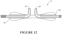
- An example nasal interface comprising two outlets is shown in Figure 12 .
- One of the nares of a user or patient receiving a flow of respiratory gases from a blower may become occluded or partially occluded, for example by a buildup of mucus in one of the nasal passages of the user.
- respiratory gases therapy provided by the respiratory system may be less effective than it otherwise would be if both nares of the user were not so blocked or partially blocked.
- a user may prefer to breath via the mouth, and in such circumstances it may be beneficial to flush the user's nasal passages with air, or to switch from providing a flow of gases between the user's nares and mouth, for example periodically.
- a system comprises a dual outlet blower 10, wherein each outlet 11, 12 provides a flow of gases to one of a pair of nasal outlets 21, 22 of a nasal interface 5.
- the dual outlet blower 10 comprises an impeller 15 and a housing comprising a first outlet 11 and a second outlet 12.
- the first outlet 11 is arranged to direct a flow of gases from the housing when the impeller rotates in a first direction of rotation
- the second outlet 12 is arranged to direct a flow of gases from the housing when the impeller rotates in an opposite second direction of rotation.
- the dual outlet blower 10 provides a means to direct a flow of gases to one of the nares of a user or the other one of the nares of a user by simply selecting a direction of rotation of the blower impeller. Where one of the nares of a user becomes blocked or partially blocked, flow may be provided to the other one of the user's nares by selecting a corresponding direction of rotation of the impeller.
- Rotation of the impeller is driven by a motor 25.
- the motor is adapted to rotate the impeller in both of a first direction of rotation and an opposite second direction of rotation. Energizing the motor to rotate the impeller in a first direction of rotation generates a flow of gases to exit the first outlet of the housing. This flow may be directed to a first nasal outlet of a nasal interface. Energizing the motor to rotate the impeller in an opposite second direction of rotation generates a flow of gases to exit the second outlet of the housing. This flow may be directed to a second nasal outlet of the nasal interface.
- a system comprises a first respiratory system between the first blower outlet 11 and a first outlet 21 of the nasal interface 5, and a second respiratory system between the second blower outlet 12 and a second outlet 22 of the nasal interface 5, wherein the first and second respiratory systems are pneumatically separate.
- the first and second respiratory systems may each comprise a conduit 3a, 3b extending between the corresponding blower outlet 11, 12 and the corresponding nasal interface outlet 21, 22.
- the nasal interface comprises a first inlet 51 in pneumatic communication with the first outlet 21 of the nasal interface via a first lumen, and a second inlet 52 in pneumatic communication with the second outlet 22 of the nasal interface via a second lumen, wherein the first and second lumens are pneumatically separate.
- a first conduit 3a may extend between the first outlet 11 of the blower and the first inlet 51 of the nasal interface
- a second conduit 3b may extend between the second outlet 12 of the blower and the second inlet 52 of the nasal interface.
- the system may comprise dual humidifiers.
- the first respiratory system between the first blower outlet 12 and the first outlet 21 of the nasal interface may comprise a first humidifier 4a
- the second respiratory system between the second blower outlet 12 and the second outlet 22 of the nasal interface may comprise a second humidifier 4b, as illustrated by the schematic of Figure 3 .
- the system may be without humidification to provide a flow of un-humidified gases to the user.
- a single humidifier may be provided upstream of the blower, to humidify a flow of gases entering the blower via the blower inlet 13.
- the respiratory system comprises a sensing arrangement to determine occlusion or partial occlusion of one of the nares of the user and control the direction of rotation of the impeller in response. If the sensing arrangement detects one of the user's nares is at least partially occluded, the sensing arrangement may cause the impeller to rotate in one of the first and second directions of rotation to generate a flow to the other one of the user's nares, and vice versa.
- the sensing arrangement may comprise a pressure or flow sensor to detect a pressure or flow to or at the user's nares to determine if one or other of the user's nares is at least partially occluded.
- the sensing arrangement may comprise a first pressure or flow sensor 61 to detect a pressure or flow to or at one of the user's nares to determine if the one of the user's nares is at least partially occluded, and a second pressure or flow sensor 62 to detect a pressure or flow to or at the other one of the user's nares to determine if the other one of the user's nares is at least partially occluded.
- a controller 40 may be provided to receive signals from the sensing arrangement to energise the motor 25 to rotate the impeller in the first or second direction depending on whether one or other of the user's nasal passages is occluded or partially occluded.
- a pressure or flow sensor may provide a signal to the controller that compares the signal to a threshold, and where the signal indicates the pressure or flow at one of the user's nares is more than or less than a predetermined threshold indicative of one nare being at least partially occluded, the controller may energise the motor to rotate the impeller in one of the first and second rotational directions to cause a flow of gases to be provided to the one of the user's nares that is not occluded.
- the sensors 61, 62 are indicated as being located at the patient interface, however the sensors may be located elsewhere in the system, for example at the outlets 11, 12 of the blower or between the blower outlets and the outlets of the nasal interface.
- a respirator system comprises a dual outlet blower 10, wherein one of the first and second outlets 11, 12 provides a flow of gases to at least one of the user's nares and the other one of the first and second outlets 11, 12 provides a flow of gases to the user's mouth.
- the respiratory support system comprises an oro-nasal interface.
- the oro-nasal mask comprises at least one nasal outlet for providing a flow of respiratory gases to a user via at least one of the user's nares, and an oral outlet for providing a flow of respiratory gases to the user via the user's mouth.
- the first outlet of the blower housing is in fluid communication with the nasal outlet of the oro-nasal interface
- the second outlet of the blower housing is in fluid communication with the oral outlet of the oro-nasal interface.
- Rotation of the impeller in a first direction of rotation generates a flow of gases to the nasal outlet
- rotation of the impeller in a second direction of rotation generates a flow of gases to the oral outlet.
- a system may comprise a controller configured to control the direction of rotation of the impeller based on at least one of a user input, a measured condition, or a predetermined condition.
- the controller may control the impeller to rotate in a direction to provide a flow to the user's mouth and to control the impeller to rotate in an opposite direction periodically to provide a flow to the user's nares, to periodically flush the user's nasal passages.
- the first blower may provide a flow of gases to one of a pair of nasal outlets of a nasal interface
- a second blower may provide a flow of gases to the other one of the pair of nasal outlets of the nasal interface.
- the first blower may provide a flow of gases to one of a nasal outlet and an oral outlet of an oro-nasal interface
- the second blower may provide a flow of gases to the other one of the nasal outlet and the oral outlet of the oro-nasal interface.
- Figure 4 illustrates a housing 70 of the blower 10.
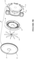
- Figures 5a and 5b show an exploded view of the blower 10, but with a motor of the blower omitted.
- a motor that may be suitable for driving the impeller is described in international patent publication WO2013/009193 , the contents of which are incorporated herein by reference.
- the blower 10 comprises the impeller 15, and the housing 70.
- the housing comprises an impeller chamber 20 ( Figure 7 ) in which the impeller rotates to generate a pressurised flow of gases, and a first outlet 11 and a second outlet 12.
- the first outlet 11 is arranged to direct a flow of gases from the housing 70 when the impeller rotates in a first direction of rotation illustrated as direction A in figure 6
- the second outlet 12 is arranged to direct a flow of gases from the housing 70 when the impeller rotates in an opposite second direction of rotation, illustrated as direction B in figure 6 .
- the housing may comprise two or more parts assembled together.
- the housing comprises a first or main housing part 71 and a second housing part or cap 72 that assembles to the first housing part 71.
- the first housing part 71 may comprise the first and second outlets, and the second housing part or cap 72 may comprise the blower inlet 13.
- the first and second inlets 11, 12 each comprise a conduit extending from a volute chamber 30 of the housing 70.
- a 'volute chamber' in a pump is a curved funnel that increases in area towards an outlet of the pump.
- the term 'volute chamber' should be interpreted broadly to mean a housing or chamber that receives air pumped by the impeller from the impeller chamber and in which the velocity of the air flow decreases to cause a relatively higher pressure.
- the volute chamber of a blower according to embodiments described herein is not necessarily volute-shaped.
- the inlet 13 is preferably located centrally with respect to a rotational axis of the impeller.
- the impeller draws air into the impeller chamber from the inlet and forces air from the impeller chamber into the volute chamber via a passage 19 between the impeller chamber 20 and the volute chamber 30.
- the air collecting in the volute chamber passes from the volute chamber via the first outlet 11 or the second outlet 12, depending on the rotational direction of the impeller.
- the impeller is illustrated as an asymmetric impeller, which is an impeller that is configured to generate more flow when rotating in one direction compared to the opposite direction.
- the impeller blades 16 may be angled from the hub 17 of the impeller and/or may be curved or otherwise shaped for the impeller to be preferentially rotated in one direction.
- the impeller may be a symmetrical impeller, for example configured with radially extending blades that are straight or otherwise shaped to give a given flow rate for a given rotational speed regardless of rotational direction.
- the impeller chamber 20 and the volute chamber 30 are separated by a dividing wall.
- the impeller chamber is separated from the volute chamber by a dividing wall 35 of the housing 70.
- the passage 19 between the impeller chamber 20 and the volute chamber 30 is an aperture in the dividing wall.
- the dividing wall does not extend fully to a side wall 36 of the volute chamber, and the passage is a gap 19 between an edge 37 of the dividing wall 35 and the side wall 36.
- the side wall may be a circumferential side wall of the blower housing.
- the passage 19 is crescent shaped.
- the gap 19 between the dividing wall and the side wall is crescent shaped.
- the gap 19 is crescent shaped, tapering on either side of a widest point 19w of the passage to a narrow point or narrow points 19n either side of the widest point.
- the widest point 19w is located midway between the first and second outlets 11, 12, as shown in Figure 6 .
- the passage 19 between the impeller chamber and the volute chamber is radially outside the blower inlet 13.
- the passage 19 is an aperture in the wall 35, preferably the aperture is adjacent to a side wall of the housing. Further, preferably the aperture is midway between the first and second outlets.
- the first and second outlets 11, 12 extend tangentially or substantially tangentially from the volute chamber.
- the outlets may extend from the housing at an angle of less than 30 degrees, or less than 20 degrees, or less than 10 degrees from a tangent to the rotational axis of the impeller.
- the first outlet 11 extends substantially tangentially from the housing with respect to a first direction of rotation of the impeller
- the second outlet 12 extends substantially tangentially from the housing with respect to an opposite second direction of rotation of the impeller.
- the first and second outlets are positioned to be mirror images of one another on a centreline of the housing or a line extending through the rotational axis of the impeller, such that the outlets are parallel and with both extending in a single lateral direction.
- the first and second outlets 11, 12 may extend from the housing to be at a right angle or 90degrees to one another.
- the outlets may be in-line and extending in opposite lateral directions.
- the first outlet 11 may extend downwards and the second outlet 12 may extend upwards and in line with the first outlet.
- the impeller is a centrifugal impeller.
- a centrifugal impeller generates a flow velocity that may be resolved into a tangential component of velocity and a radial component of velocity.
- the first outlet is arranged to extend from the housing to receive at least a substantial portion of a tangential component of velocity of air flow generated by the impeller when rotating in a first direction of rotation
- the second outlet is arranged to extend from the housing to receive at least a substantial portion of a tangential component of velocity of air flow generated by the impeller when rotating in a second direction of rotation.
- blower arrangement is configured to provide flow to a selected outlet and therefore a selected one of the nares of a user or a selected one of the user's nose and mouth, by motor direction control and without the requirement for other devices such as valves and valve actuation devices.
- rotation of the impeller in a first direction of rotation generates a first flow of gases from the first outlet and a second flow of gases from the second outlet, wherein the first flow of gases is greater than the second flow of gases.
- rotation of the impeller in the opposite second direction of rotation generates the first flow of gases from the second outlet and the second flow of gases from the first outlet.
- rotation of the impeller in a first direction of rotation generates a first flow of gases from the first outlet and a second flow of gases from the second outlet
- rotation of the impeller in an opposite second direction of rotation generates a third flow of gases from the second outlet and a fourth flow of gases from the first outlet
- the flow rate of the first flow of gases is greater than the flow rate of the second flow of gases
- the flow rate of the third flow of gases is greater than the flow rate of the fourth flow of gases.
- the third flow rate is substantially equal to the first flow rate
- the fourth flow rate is substantially equal to the second flow rate.
- the housing 10 provides a motor chamber 60, for housing the motor within the housing of the blower.
- the volute chamber 30 extends around the motor chamber 60.
- the motor is located radially inside of the annular volute chamber 30.
- the motor is located radially inside of the annular volute chamber.
- An aperture is provided between the motor chamber and the impeller chamber so that a shaft of the motor or impeller can extend between the impeller and the motor to rotationally couple the impeller to the motor. Positioning the motor radially inside of the annular volute achieves a flat (small axial length) blower configuration.
- the blower may comprise one or more electronic circuit boards, for example the blower may include motor control electronics.
- the electronics may be provided remotely from the blower.
- a cable to the blower may provide communications and motor control current and/or voltage from a remote motor controller to the motor.
- Blocked flow indicates pressure generated at the blower outlets 11, 12 with the outlets blocked.
- Bias resistance flow is the flow that vents from the patient interface (e.g. nasal cannula 5 in Figure 3 ) when the outlets from the interface are blocked. For example, there is a leak at the interface with a resistance that vents approximately 30 to 40 lpm at 10cmH 2 O. Bias flow is the minimum leak in the respiratory system independent of inhalation and exhalation by the patient.
- Open flow is the flow rate that is achieved at the outlets 11, 12 with no downstream flow resistance.
- the flow rate from one outlet is about 20% of the flow from the other outlet.
- this significant difference in flow from the two outlets is not experienced in practice.
- the flow rate from one outlet is about 80% of the flow from the other outlet.
- the blower provides a flow in the range of between blocked flow (no flow) and bias flow, and during inspiration the peak flow provided by the blower including bias flow may be approximately 80lpm at 10K rpm.
- the flow rate from one outlet may be approximately one third of the flow from the other outlet.
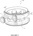
- FIG. 9 An alternative blower 110 is described with reference to Figures 9 to 11 .
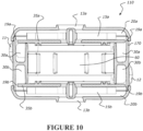
- An alternative housing 170 is illustrated in Figure 9 , and a cross section of the blower 110 with motor omitted is shown in Figure 10 .
- a blower comprising the housing of Figure 9 comprises two impellers 15a and 15b, as illustrated in Figure 10 .
- the two impellers are axially spaced apart.
- the housing 170 comprises a first impeller chamber 20a for receiving a first impeller 15a, and a second impeller chamber 20b for receiving a second impeller 15b.
- a first dividing wall 35a separates the first impeller chamber 20a from a first volute chamber 30a.
- a second dividing wall 35b separates the second impeller chamber 20b from a second volute chamber 30b.
- the housing 170 may comprise a single volute chamber that receives a flow of gases from both of the first and second impeller chambers. Each impeller chamber communicates with the volute chambers or chamber via an aperture or gap 19a, 19b as described with reference to the embodiment of Figures 4 to 8 .
- the housing comprises a single motor chamber 60.
- a motor comprising a stator and rotor is located in the motor chamber. The motor chamber and motor are located axially between the first impeller chamber and the second impeller chamber. The rotor is coupled to the first and second impellers 15a and 15b, so that the rotor and the first and second impellers rotate together.
- first impeller In a first direction of rotation the first impeller generates a flow of gases to exit the first volute chamber or the volute chamber via the first outlet 11. In a second direction of rotation the second impeller generates a flow of gases to exit the second volute chamber or the volute chamber via the second outlet 12.
- the motor 25 comprises a rotor 26 coupled to the first and second impellers 15a, 15b by a shaft 28.
- the rotor is positioned inside stator 27 and supported by bearing elements 29 to rotate relative to the stator 27.
- the bearing elements are supported by bearing mounts 31.
- the bearing mounts may be resilient, for example formed from an elastomer.
- the bearing elements are supported by the bearing mounts 31 located between the stator and the bearing elements, with the bearing elements located on the shaft.
- the stator is supported in the motor chamber 60 of the blower housing 170.
- a resilient mount may be provided to mount the stator within the motor chamber 60.
- a similar motor and impeller arrangement may be utilized in the blower 10 described with reference to Figures 4 to 8 , but with a single impeller coupled to a shaft 27 extending from one end of the motor.
- blowers illustrated in Figures 4 to 8 and in Figures 9 and 10 are centrifugal blowers, comprising a centrifugal impeller (or impellers) with a housing to generate tangential air flows.
- a dual outlet blower may comprise an impeller or impellers and a housing to generate axial air flows.
- a blower comprising an impeller comprises a first axial outlet at a first side of the blower and a second axial outlet at a second side of the blower. In a first direction of rotation the impeller generates a flow of gases to exit the first axial outlet of the housing. In a second direction of rotation the impeller generates a flow of gases to exit the second axial outlet of the housing.
- the blower comprises a housing with a first impeller chamber for receiving a first impeller, and a second impeller chamber for receiving a second impeller, and a first axial outlet associated with the first impeller chamber and a second axial outlet associated with the second impeller chamber.
- the housing may also comprise a single motor chamber.
- a motor comprising a stator and rotor is located in the motor chamber.
- the motor chamber and motor may be located axially between the first impeller chamber and the second impeller chamber.
- the axial blower may comprise a dual impeller and rotor configuration like the configuration shown in Figure 12 , wherein the rotor is coupled to the first and second impellers, so that the rotor and the first and second impellers rotate together.
- first impeller In a first direction of rotation the first impeller generates a flow of gases to exit the first axial outlet of the housing. In a second direction of rotation the second impeller generates a flow of gases to exit the second axial outlet of the housing.
- the impeller or impellers may be centrifugal impellers.
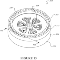
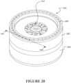
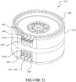
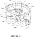
- the blower 210 comprises a housing 270.
- the housing may comprise a first housing part 271 and a second housing part 272.
- the housing comprises a first wall 273 and a second wall 274 axially spaced apart by a circumferential wall 275.
- the first and second walls and the circumferential wall combine to form an impeller chamber 20 for receiving the impeller 215.
- the first and second walls are preferably planar and perpendicular to a rotational axis of an impeller of the blower. In the illustrated embodiment the first and second walls are annular.
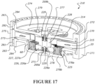
- the housing further comprises a first central hub 276 and a second central hub 277.
- the first central hub 276 is connected via radial ribs 278 to an inner perimeter of the first annular wall 273.
- the second central hub 277 is connected via ribs 279 to an inner perimeter of the second annular wall 274.
- the ribs connecting each hub to the respective annular wall extend radially between the hub and annular wall.
- the radial ribs 278 extending between the first annular wall 273 and the first central hub 276 comprise an axial extending portion 278a and a radial extending portion 278b, so that the first central hub 276 is axially spaced from the first annular wall 273 and axially away from the impeller chamber 20.
- the recessed region forms a motor chamber 60 for receiving a motor 225 comprising a stator 227 and rotor 226.
- the first hub 276 acts as a support for the stator, and at least a partial support for a first bearing 229, which in turn provides support for the rotor 226 and an impeller 215 assembly. Apertures or gaps 213 between ribs 278 provide a first axial inlet 213. This provides motor cooling also.
- the second central hub 277 provides at least a partial support for a second bearing, which in turn also provides support for the rotor 226 and an impeller 215 assembly.
- apertures or gaps 214 between ribs 279 provide a second axial inlet 214.
- the motor 225 comprises the stator 227 and rotor 226.
- the stator is supported by the radial ribs 278 and is located radially by the axial portions 278a of the ribs and axially by the radial portions 278b of the ribs.
- the stator 227 comprises an annular stacked laminated core 227a with a toroidal winding 227b.
- the rotor comprises an annular or toroidal magnet 226a coupled to a shaft 228.
- the lower end of the shaft has an annular rebate 228a with an external diameter commensurate with the inner diameter of the annular magnet 226a for receiving the annular magnet.
- the shaft 228 may be a cylindrical tube in the form of a bearing tube.
- a bearing e.g.
- Each bearing may comprise an outer annular bearing race/housing, an inner annular bearing race/housing and ball or roller bearings movable therebetween.
- the bearings can have an outside diameter of about 4mm to 8mm, an inside diameter of about 1.5mm to 3mm and a thickness of about 2mm to 4mm.
- the outer bearing race rotates relative to the inner bearing race.
- the inner bearing race can remain stationary. In alternatives, a plane bearing or bushing could be used instead.
- the shaft 228 is supported between the first and second central hubs.
- Both the first and second housing parts comprise stub axles 269a, 269b extending from the central hub in the form of compliant and/or resilient protrusions that extend into and couple to the respective bearing at each end of the shaft.
- the protrusions extend into and couple to the bearing race of the respective bearing.
- the stub axles are formed from an elastomer (e.g. silicone) or other compliant and/or resilient material, and have a friction fit within the respective bearing races.
- the stub axles could be solid and/or rigid and are over-moulded with a resilient and/or flexible material.
- the stub axles could be solid.
- the stub axle/bearing arrangement enables the shaft to be rotatably supported/coupled in a simply supported manner to the first and second hubs.
- the outer diameter of the outer bearing race could be about 4mm, for example.
- the hollow shaft could have a commensurate diameter of about 4mm to allow for a snug fit of the bearing race.
- the outer shaft size in the rebate 228a could be about 5mm.
- the impeller 215 can be coupled onto (e.g. press fit) or integrally formed with the shaft 228.
- the shaft can be of similar diameter to the shaft in traditional topologies, which allows for robust mechanical coupling of the impeller. Because the bearings are fitted on the inside of the shaft, the diameter of the shaft is not dictated by the inner diameter of the bearings.
- the outer diameter of the shaft can then be a suitable size to allow for a robust impeller coupling, e.g. about 5mm, or alternatively from about 3mm to about 5mm.
- a larger diameter shaft can still be used without dictating the bearing diameter size (leading to undesirably high bearing speeds), because the bearings are internal to the shaft, the size of the bearing (e.g. the diameter size) can be selected based on acceptable bearing speed.
- the magnet/rotor 226a/226 is pressed into the shaft. Similar advantages apply here, where the shaft can be a suitable size to allow for robust coupling.
- the impeller 215 comprises a hub portion 217 and (full-length) blades (sometimes called “vanes") 216, which radially extend from and connect to the hub portion.
- the blades extend radially from the hub, but other arrangements may be possible, for example the blades may be angled forward in relation to a direction of rotation of the impeller.
- the blades may be flat or straight, or the blades may be curved.
- An annular rib/ring 218 extends between the full length blades to provide rigidity towards the perimeter of the blades.
- the ring may taper in thickness towards outer and inner radial edges, as shown in Figure 17 .
- a plurality of short stub (partial-length) blades 216b that extend part-way to the hub are interspaced between the full length blades 216.
- the annular rib 218 also extends between the stub blades 216b, thus supporting them from the full length blades.
- the stub blades provide additional pressure normally achieved with additional blades, without the requirement for material to extend to the hub which reduces air space at the hub. Reducing airspace at hub reduces the maximum flow capability of the blower 210. If the number of blades is too high (and therefore there is too little air space at the hub due to too many blades), inlet flow is occluded, which restricts the outlet airflow of the blower.
- Hz rotation rate
- Human hearing is sensitive to tonal inputs between 300 Hz and 15 kHz and if not melodious, it is classified as noise.
- High frequency sound waves are easier to attenuate than low frequency noise.
- Typical CPAP blowers have rotational speeds of around 180 revolutions per second. It is therefore advantageous to increase the blade count to improve attenuation characteristics.
- Unequal, dissimilar and prime numbers like 7, 11, 13, 17, 19 and 23 help to reduce common fraction interactions between rotor and stator.
- decelerating a fluid by increasing the flow area rapidly can result in boundary layer separation, flow reversals and turbulent losses.
- Pressure loss recovery via diffusion mechanisms dictate that the angle between blades should not exceed 12 degrees. Dividing the full circumference (360 degrees) by the sum of the blade thickness angle and the flow channel angle, a minimum blade number for optimal diffusion can be calculated. Adding more blades than optimal reduces the flow channel size with an increase in pressure drop.
- splitter blades To minimise occlusion closer to the hub some blades may be truncated, referred to as splitter blades. Splitter blades could be placed on a support disc or shrouds to transfer their part of the load to the hub. But, blisks (bladed disks) and shrouded impellers have much higher rotational inertia. The present inventors have avoided this by supporting the splitter blades on a rib 218 as described, which reduces inertia over a shroud or disc, and also minimises occlusion.
- the housing comprises a first stator ring 281 that encircles the first wall 273, and a second stator ring 282 that encircles the second wall 274.
- Each stator ring comprises an outer circumferential wall 283 and an inner circumferential wall 284.
- the outer circumferential wall of the first and/or second stator ring extends axially from the stator ring to form the circumferential wall 275 of the impeller chamber 20.
- the circumferential wall 275 of the impeller chamber is integrally formed with and extends axially from the outer circumferential wall 283 of the first stator ring.
- the outer circumferential wall 284 of the second stator ring 282 of the second housing part 272 abuts the circumferential wall 275 of the impeller housing 20 of the first housing part 271.
- the first and second housing parts 271, 272 may be held together by way of bayonets, bumps, snap fits, glue, ultrasonic or friction welding, or any other suitable means.
- a stator ring is a stationary ring of flow paths.
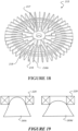
- each of the first and second stator rings 281, 282 curved channels e.g. 285, 286 (see Figure 16 ) are formed between the inner and outer circumferential walls 283, 284 for receiving and slowing airflow from the impeller 215 to create pressure.
- each of the first and second stator rings 281, 282 provide a ring of small volute chambers or volute paths 285, 286 spaced apart circumferentially in a ring.
- the volute paths 285, 286 are located radially outside of the impeller 215 or are located adjacent to or at the radial outer perimeter of the impeller blades 216, 216b of the impeller.
- the first and second stator rings 281, 282 provide first and second axial outlets 285, 286.
- the volute paths 285, 286 of the first and second stator rings 281, 282 provide the first and second axial outlets.
- each of the first and second axial outlets comprises a plurality of outlet paths, each outlet path being a volute path.
- a volute path has an increasing area perpendicular to the air flow direction at least part way through the volute path so that the speed of the air flow decreases along the volute path to increase pressure of the flow.
- the circumferential or radial width or both may increase in dimension from the impeller chamber end of the volute path to the outlet end of the volute path.
- the volute paths 285 of the first stator ring 281 are arranged to receive a larger portion of a tangential component of velocity of air flow from the impeller 215 when rotating in a first direction of rotation, compared to the volute paths 286 of the second stator ring 282. And with the impeller rotating in a second opposite direction of rotation, the volute paths 286 of the second stator ring 282 are arranged to receive a larger portion of a tangential component of velocity of air flow from the impeller 215, compared to the volute paths 285 of the first stator ring 281.
- volute paths 285 of the first stator ring 281 extend from the impeller chamber 20 to receive at least a substantial portion of a tangential component of velocity of air flow generated by the impeller 215 when rotating in a first direction of rotation
- volute paths 286 of the second stator ring 282 extend from the impeller chamber 20 to receive at least a substantial portion of a tangential component of velocity of air flow generated by the impeller 215 when rotating in a second direction of rotation.
- the impeller 215 is a symmetric impeller and the first and second stator rings 281, 282 are identical but for one stator ring being inverted by 180 degrees on the rotational axis of the impeller relative to the other stator ring, such that rotation of the impeller in a first direction of rotation generates a first flow of gases from the first outlet and a second flow of gases from the second outlet, and rotation of the impeller in the opposite second direction of rotation generates the first flow of gases from the second outlet and the second flow of gases from the first outlet.
- the first flow of gases is greater than the second flow of gases.
- impeller and/or stator rings may be arranged to provide different flows from the first and second axial outlets for a given speed in the first and second rotational directions.
- volute paths 285 in the first stator ring curve 281 from the impeller chamber 20 from a tangential direction of the impeller 215 rotating in the first direction of rotation and towards a first axial direction I of the blower.
- the volute paths 286 in the second stator ring 282 curve from the impeller chamber 20 from an opposite tangential direction of the impeller rotating in the second opposite direction of rotation and towards a second axial direction II of the blower.
- volute paths 285 of the first stator ring curve from the first axial direction I towards a tangential direction of the impeller rotating in the second rotational direction
- volute paths 286 of the second stator ring 282 curve from the second axial direction II towards an opposite tangential direction of the impeller rotating in the first rotational direction.
- each volute path 285, 286 is separated from an adjacent volute path by a curved rib or vane 287.
- each curved rib 287 has a width extending in the circumferential direction of the stator ring that increases along the axial length of the rib from the impeller chamber towards the axial outlet end of the rib.
- the circumferential width of the curved rib 287 tapers to a point at the impeller chamber end of the rib.
- the motor 225 is controlled using a power supply and a controller to rotate the impeller to create the desired output air flow (both pressure and/or flow rate). Air is drawn through the apertures 213, 214 forming the axial inlets by rotation of the impeller, including over the motor to provide cooling, and directed to the first and second stator rings 281, 282 via the impeller blades. In a first direction of rotation more of a tangential velocity component of the air flow generated by the impeller is received by the first stator ring 281 than the second stator ring 282 so that a larger pressure/flow is generated at the first axial outlet 285 than at the second axial outlet 286.
- a second direction of rotation In a second direction of rotation more of a tangential velocity component of the air flow generated by the impeller is received by the second stator ring 282 than the first stator ring 281 so that a larger pressure/flow is generated at the second axial outlet 286 than at the first axial outlet 285.
- rotation of the impeller in a first direction of rotation generates a first flow of gases from the first outlet 285 and a second flow of gases from the second outlet 286, wherein the first flow of gases is greater than the second flow of gases.
- Each stator ring slows the flow to create pressure, and the flow is directed axially out the stator ring/axial outlet of the blower.
- the blower may comprise a single axial inlet only.
- the blower may comprise the first axial inlet 213 only, comprising the gaps or apertures 213 between the ribs 278 supporting the first hub 276 from the first annular wall 273.
- the second wall 274 may be a disk or plate or continuous cover extending within the circumferential wall 275 of the housing 270, with the second central hub 277 formed at a centre of the second wall 274 and without ribs and corresponding apertures around the second central hub.
- the blower may comprise the second axial inlet 214 only, comprising the gaps or apertures 214 between the ribs 279 supporting the second hub 277 from the second annular wall 274.
- the first wall 273 may comprise an annular wall section and a recessed wall section radially within the annular section for receiving the motor 225, with the first central hub 276 formed at a centre of the recessed section and without ribs and corresponding apertures around the first central hub.
- each stub axle might not extend through the bearings. Rather each stub axle might only partially extend into (e.g. see stub axle 269c), or just contact (e.g. see stub axle 269d) the bearing. These arrangements still provide sufficient support and allow for rotation.
- motors are possible, and those described are exemplary only.
- a brushed or brushless DC motor, AC motor, inductance motor or variable reluctance motor could be used.
- the rotor and stator could take other forms to that described.
- the dual axial embodiment described has a number of advantages. It provides a reduced footprint blower, both in profile and/or plan. A smaller foot print allows for a smaller housing. One reason for the smaller foot print is that the stator rings allow for a volute chamber or chambers to be omitted, reducing overall diameter and/or height of the blower, and also increases the ratio of blade length to housing diameter (that is, the space for blade length is not reduced due to the presence of a volute chamber allowing the blade length to use more of the available footprint diameter than a housing with a volute chamber).
- the embodiment also allows for the use of a smaller impeller (that is, smaller in diameter, thickness and/or weight). This in turn leads to a smaller/lighter blower and/or a blower with a lower inertia.
- a smaller/lighter topology enables the blower to be used in portable, miniaturised and/or head or mask mounted CPAP, high flow therapy or other breathing apparatus.
- the impeller might have a diameter of about 47mm inside an about 48mm diameter ring providing a ratio of blade length to housing diameter of 98%.
- Another example is about 18mm blades in an about 20mm radius housing for a 90% ration.
- the embodiment of Figure 13 may overcome one or more of these issues and allow for the use of a smaller impeller in a single-stage blower.
- the shaft that is used is hollow, or at least partially hollow. Bearings are fitted to the inside of the shaft. This allows for two things. First it allows for the shaft diameter to be of the same or similar size as previously, so that an impeller and/or rotor (or magnet) can be integrated into or fitted to a shaft in the usual manner; and second because the bearings are disposed internally, it allows for smaller diameter bearings (while still having the same is diameter shaft) to be used. This then allows the impeller to be spun at higher speeds to create the required flow rate and/or pressure with a smaller diameter impeller.
- the stub axles therefore allow for connection to the internal races of the bearings, and the compliance/resilience of the stub axles allow for compliance when the shaft spins.
- the arrangement also reduces or eliminates eddy currents in the shaft and/or bearings. The eddy currents can degrade the bearings.
- the stub blades and increased air inlet numbers and/or size allow for more pressure to be generated from a smaller blade length.
- the axial outlet eliminates the need for a tangential outlet duct, which can increase the blower footprint.
- the arrangement also allows for a single stage (dual) axial input/dual axial output blower, which provides for a reduced footprint or lower (low) profile.
- the embodiment described does not have a volute chamber which reduces the size also.
- the stator rings create static pressure.
- the axial airflow inlet allows for cooling of the motor stator.
- a dual axial outlet blower 310 may comprise two impellers 315a and 315b, as illustrated in Figure 23 .
- the two impellers are axially spaced apart.
- the housing 370 comprises a first impeller chamber 20a for receiving a first impeller 315a, and a second impeller chamber 20b for receiving a second impeller 315b.
- the housing comprises a first wall 373a and a second wall 374a axially spaced apart by a circumferential wall 375a.
- the first and second walls and the circumferential wall combine to form the first impeller chamber 20a for receiving the first impeller 315a, as described above in relation to the earlier single impeller embodiment.
- the housing 370 comprises a third wall 373b and a fourth wall 374b axially spaced apart by a second circumferential wall 375b.
- the third and fourth walls and the second circumferential wall combine to form the second impeller chamber 20b for receiving the second impeller 315b.
- the first, second, third and fourth walls are annular.
- the first and second impeller chambers 20a, 20b may be identical but for one impeller chamber being inverted by 180 degrees on the rotational axis of the impellers relative to the other impeller chamber.
- the housing further comprises a first central hub 376 and a second central hub 377.
- the first central hub is connected via radial ribs 378 to an inner perimeter of the first annular wall 373a.
- the second central hub 377 is connected via ribs 379 to an inner perimeter of the third annular wall 373b.
- the ribs connecting each hub to the respective annular wall extend radially between the hub and annular wall.
- the first hub 376 provides at least a partial support for a first bearing 229, which in turn provides support for a rotor 226 and dual impeller 315a, 315b assembly. Apertures or gaps 313 between ribs 378 provide a first axial inlet.
- the second central hub 377 provides at least a partial support for a second bearing 229, which in turn also provides support for the rotor 226 and dual impeller 315a, 315b assembly. In some embodiments, apertures or gaps 314 between ribs provide a second axial inlet.
- the housing 370 comprises a single motor chamber 60.
- a motor comprising a stator 227 and rotor 226 is located in the motor chamber.
- the motor chamber and motor are located axially between the first impeller chamber 20a and the second impeller chamber 20b.
- the motor chamber 60 may be provided by a circumferential wall extending between the second and fourth walls of the housing 370.
- the rotor 226 is coupled to the first and second impellers 315a and 315b, so that the rotor and the first and second impellers rotate together.
- FIG. 24 An example rotor and dual impeller configuration for use in the blower 310 is shown in Figure 24 .
- the rotor and impeller arrangement may be similar or the same as that described above with reference to Figure 17 , but with a shaft 328 of sufficient length to support the rotor magnet 226a midway along the shaft 328 and with the first and second impellers 315a, 315b located at respective ends of the shaft or on the shaft on either axial side of the rotor magnet.
- the shaft may be formed in two parts press fit or otherwise secured together within or to the rotor. Each part of the shaft may be press fit or otherwise connected to or integrally formed with a respective one of the two impellers.
- the rotor is positioned inside stator 227 and supported by bearing elements on stub axles 269a, 269b at the first and second hubs 376, 377 as described for the earlier embodiment of Figure 13 comprising a single impeller.
- a resilient mount may be provided to mount the stator within the motor chamber 60.
- the first and second impellers 315a, 315b may be identical, but with one impeller being inverted by 180 degrees on the rotational axis of the impeller relative to the other impeller.
- An exemplary first and second impeller is shown in Figures 23 in more detail (wherein the first and second impellers are identical).
- the impeller 315a, 315b comprises a hub portion 317 and flat forward swept (full-length) blades (sometimes called "vanes") 316, which radially extend from and connect to the hub portion. (Alternatively, the blades could be backward swept or radial). Each blade comprises a vertical (parallel to the rotational axis) flat portion extending from the hub 317.
- An annular rib/ring 318 is formed into the blades 316 and extends between them to provide rigidity at the perimeter of the blades.
- the ring curves towards the respective stator ring outlet 381, 382 to provide rigidity to the blades and also direct airflow through the corresponding stator ring.
- a plurality of short stub (partial-length) blades 316b (also termed "splitter blades") that extend part-way to the hub are interspaced between the full length blades 316. In the illustrated exemplary embodiment, there are three stub blades in-between each pair of adjacent full length blades.
- the annular rib 318 is also formed into and extends between the stub blades 316b, thus supporting them.
- the stub blades provide additional pressure normally achieved with additional blades, without the requirement for material to extend to the hub which reduces air space at the hub. Reducing airspace at hub reduces the maximum flow capability of the blower 310. If the number of blades is too high (and therefore there is too little air space at the hub due to too many blades), inlet flow is occluded, which restricts the outlet airflow of the blower.
- the impeller of Figure 23 has the same associated benefits as described above in relation to the single impeller dual axial outlet blower described above with reference to Figures 13 to 19 , however is further optimised with forwardly curved blades with respect to a rotational direction to preferentially generate pressure dependent on the direction of rotation.
- the housing comprises a first stator ring 281 that encircles the first annular wall 373, and a second stator ring 282 that encircles the third annular wall 373b.
- the stator rings 281, 282 are as described above in relation to the single impeller embodiment of Figure 13 .
- the first impeller 315a is arranged so that the ring 318 of the impeller curves to the volute paths 285 of the first stator ring 281, and the second impeller 315b is arranged so that the ring 318 of the impeller curves to the volute paths 286 of the second stator ring 282.
- the first impeller When the rotor 226 and first and second impeller 315a, 315b assembly rotates, the first impeller generates a pressure and flow at the first stator ring 281 and the second impeller generates a pressure and flow at the second stator ring 282.
- the blades of the first impeller 315a are swept or curved forwards and the blades of the second impeller 315b are swept or curved backwards. Due to the opposite curvature of the blades of the first and second impellers, when rotating in a first direction of rotation the first impeller generates a greater pressure at the first stator ring 281 than the second impeller generates at the second stator ring 282.
- the volute paths of the first stator ring are arranged to receive a larger portion of a tangential component of velocity of air flow from the first impeller when rotating in the first direction of rotation compared to when rotating in the second direction of rotation.
- the volute paths of the second stator ring are arranged to receive a larger portion of a tangential component of velocity of air flow from the second impeller when rotating in the second direction of rotation compared to when rotating in the first direction of rotation.
- rotation of the impeller in a first direction of rotation generates a first flow of gases from the first outlet 285 and a second flow of gases from the second outlet 286, wherein the first flow of gases is greater than the second flow of gases.
- volute paths 285 of the first stator ring 281 extend from the first impeller chamber 20a to receive at least a substantial portion of a tangential component of velocity of air flow generated by the first impeller when rotating in a first direction of rotation
- volute paths 286 of the second stator ring 282 extend from the second impeller chamber 20b to receive at least a substantial portion of a tangential component of velocity of air flow generated by the second impeller when rotating in a second direction of rotation.
- the first impeller 315a and the first stator ring 281 are identical to the second impeller 315b and the second stator ring 282 but for one impeller and stator ring being inverted by 180 degrees on the rotational axis of the impeller relative to the other impeller and stator ring, such that rotation of the impeller and rotor assembly in a first direction of rotation generates a first flow of gases from the first outlet and a second flow of gases from the second outlet, and rotation of the impeller in the opposite second direction of rotation generates the first flow of gases from the second outlet and the second flow of gases from the first outlet.
- the first flow of gases is greater than the second flow of gases.
- impeller and/or stator rings may be arranged to provide different flows from the first and second axial outlets for a given speed in the first and second rotational directions.
- the motor is controlled using a power supply and a controller to rotate the impeller to create the desired output air flow (both pressure and/or flow rate).
- Air is drawn through the apertures of the axial inlets by rotation of the rotor and dual impeller assembly, and directed to the first and second stator rings via the first and second impellers.
- Each stator ring slows the flow to create pressure, and the flow is directed axially out the stator ring/axial outlet of the blower.
- the axial outlet blowers described above may also comprise a first outlet manifold and a second outlet manifold.
- the first outlet manifold may comprise an inlet to receive flow from the outlets 282 of the first stator ring, and direct the flow from the first stator ring to an outlet of the first outlet manifold.
- the second outlet manifold may comprise an inlet to receive flow from the outlets 282 of the second stator ring, and direct the flow from the second stator ring to an outlet of the second outlet manifold.
- the outlet of each of the first and second outlet manifolds may be a single outlet, and may be an axial outlet.
Landscapes
- Health & Medical Sciences (AREA)
- Engineering & Computer Science (AREA)
- Pulmonology (AREA)
- Hematology (AREA)
- Animal Behavior & Ethology (AREA)
- Veterinary Medicine (AREA)
- Emergency Medicine (AREA)
- Anesthesiology (AREA)
- Biomedical Technology (AREA)
- Heart & Thoracic Surgery (AREA)
- Public Health (AREA)
- Life Sciences & Earth Sciences (AREA)
- General Health & Medical Sciences (AREA)
- Mechanical Engineering (AREA)
- General Engineering & Computer Science (AREA)
- Otolaryngology (AREA)
- Structures Of Non-Positive Displacement Pumps (AREA)
- Respiratory Apparatuses And Protective Means (AREA)
- Measuring Volume Flow (AREA)
- Medicinal Preparation (AREA)
Abstract
Description
- The present disclosure relates to a respiratory support system comprising a blower for providing a flow of respiratory gases to a patient or user, and a blower for a respiratory support system.
- A blower (gases supply unit) is used to generate a flow of respiratory gases to be provided to a patient or user for the treatment of respiratory health issues. For example, continuous positive airway pressure devices and/or systems for treating sleep apnea comprise a blower for providing a flow of positive pressure air to support a user's airways. In many cases, a blower is used together with a humidifier to provide a flow of humidified gases to a user. A respiratory system may include an integrated gases supply device which comprises both a humidifier and a blower. A prior art integrated gases supply device is described in international patent publication
WO2013/009193 . - A schematic representation of a modular respiratory system is provided in
Figure 1 . The system comprises ablower 2 in fluid communication with ahumidifier 4 via a conduit. Afurther conduit 3 provides a flow of gases generated byblower 2 and humidified by the humidifier to auser 1 via apatient interface 5. A further schematic representation is provided inFigure 2 , representing an integrated blower and humidification unit 6 that comprises ablower 2 andhumidifier 4 in a single integrated unit. - In the systems of
Figures 1 and2 , thepatient interface 5 may be a full face mask that provides a flow of gases to the user's airways via the user's mouth and nose, or may be an oral interface or a nasal interface. A nasal interface may seal against the users face around the nose, or may engage with the user's nares, in either a sealing or non-sealing way. For example a nasal cannula may provide a pair of prongs to engage with the user's nares without forming an air tight seal. Alternatively a nasal interface may comprise a pair of nasal pillows that sealingly engage the nares of a user. - In this specification where reference has been made to patent specifications, other external documents, or other sources of information, this is generally for the purpose of providing a context for discussing the features of the invention. Unless specifically stated otherwise, reference to such external documents is not to be construed as an admission that such documents, or such sources of information, in any jurisdiction, are prior art, or form part of the common general knowledge in the art.
- It is an object of the present invention to provide an improved blower or respiratory support system, or to at least provide the industry or public with a useful choice.
- In accordance with at least one of the embodiments disclosed herein, a blower for providing a flow or respiratory gases comprises a respiratory (support) system comprising a dual outlet blower, wherein one of a first and a second outlet of the blower provides a flow of gases to one of a pair of nasal outlets of a nasal interface and the other one of the first and second outlets provides a flow of gases to the other one of the pair of nasal outlets of the nasal interface, or wherein one of the first and second outlets provides a flow of gases to a nasal outlet of a oro-nasal interface and the other one of the first and second outlets provides a flow of gases to an oral outlet of the oro-nasal interface.
- In some embodiments, the blower comprises:
- an impeller, and
- a housing comprising an impeller chamber in which the impeller rotates and the first outlet and the second outlet, the first outlet arranged to direct a flow of gases from the housing when the impeller rotates in a first direction of rotation, and the second outlet arranged to direct a flow of gases from the housing when the impeller rotates in an opposite second direction of rotation.
- In some embodiments, with rotation of the impeller in the first direction of rotation, a flow of gases from the first outlet is greater than a flow of gases from the second outlet, and
with rotation of the impeller in the second direction of rotation, a flow of gases from the second outlet is greater than a flow of gases from the first outlet. - In some embodiments, rotation of the impeller in a first direction of rotation generates a first flow of gases from the first outlet and a second flow of gases from the second outlet, and
- rotation of the impeller in an opposite second direction of rotation generates the first flow of gases or a third flow of gases from the second outlet and the second flow of gases or a fourth flow of gases from the first outlet, and
- the flow rate of the first flow of gases is greater than the flow rate of the second flow of gases, and the flow rate of the third flow of gases is greater than the flow rate of the fourth flow of gases.
- In some embodiments, the flowrate of the first flow of gases is substantially the same as the flowrate of the third flow of gases.
- In some embodiments, the blower comprises a motor for driving rotation of the impeller, and the housing comprises the impeller chamber and a motor chamber for supporting the motor within the housing.
- In some embodiments, the blower comprises a first impeller and a second impeller, and the housing comprises a first impeller chamber in which the first impeller rotates and a second impeller chamber in which the second impeller rotates, and
wherein the first and second impellers are rotationally coupled to rotate together, the first impeller for generating a flow of gases from the first outlet when the first and second impellers rotate in the first direction of rotation, and the second impeller for generating a flow of gases from the second outlet when the first and second impellers rotate in the second direction of rotation. - In some embodiments, the blower comprises a motor for driving rotation of the first and second impellers, the motor comprising a rotor and a stator, wherein the first and second impellers are rotationally coupled to the rotor.
- In some embodiments, the rotor is positioned axially between the first and second impellers, and
wherein the housing comprises a motor chamber for the motor located axially between the first and second impeller chambers. - In some embodiments, the impeller is a centrifugal impeller.
- In some embodiments, the housing comprises a volute chamber receiving a flow of gases from the impeller chamber.
- In some embodiments, the first outlet extends substantially tangentially from the housing with respect to a first direction of rotation of the impeller, and the second outlet extends substantially tangentially from the housing with respect to an opposite second direction of rotation of the impeller.
- In some embodiments, the volute chamber receives a flow of gases from the first and second impeller chambers.
- In some embodiments, the housing comprises:
- a first volute chamber to receive a flow of gases from the first impeller chamber, the first outlet arranged to direct the first flow of gases from the first volute chamber, and
- a second volute chamber to receive a flow of gases from the second impeller chamber, the second outlet arranged to direct the second flow of gases from the second volute chamber.
- In some embodiments, the first and second outlets are axial outlets
- In some embodiments, the first outlet is an axial outlet at a first side of the blower and the second outlet is an axial outlet at a second side of the blower.
- In some embodiments, the housing comprises a first stator ring and a second stator ring, each stator ring comprising a plurality of volute paths, the first axial outlet comprising the volute paths of the first stator ring, and the second axial outlet comprising the volute paths of the second stator ring.
- In some embodiments, each stator ring comprises a plurality of curved vanes, each said volute path separated from an adjacent volute path in the stator ring by a said curved vane.
- In some embodiments, each stator ring comprises the plurality of curved vanes spaced circumferentially apart radially outside of or adjacent to or at the radial outer perimeter of the impeller or a respective one of a first impeller and a second impeller.
- In some embodiments, the blower comprises:
- an impeller, and
- a housing comprising an impeller chamber in which the impeller rotates and the first outlet and the second outlet, wherein:
- rotation of the impeller in a first direction of rotation generates a first flow of gases from the first outlet and a second flow of gases from the second outlet, and
- rotation of the impeller in an opposite second direction of rotation generates the first flow of gases or a third flow of gases from the second outlet and the second flow of gases or a fourth flow of gases from the first outlet, and
- the flow rate of the first flow of gases is greater than the flow rate of the second flow of gases, and the flow rate of the third flow of gases is greater than the flow rate of the fourth flow of gases.
- In some embodiments, the blower comprises:
- an impeller, and
- an impeller housing comprising the first outlet and the second outlet, the first outlet extending substantially tangentially from the housing with respect to a first direction of rotation of the impeller, and the second outlet extending substantially tangentially from the housing with respect to an opposite second direction of rotation of the impeller.
- In some embodiments, the system comprises the nasal interface, the interface comprising a first nasal outlet for providing a flow of respiratory gases to a user via one of the user's nares, and a second nasal outlet for providing a flow of respiratory gases to the user via the other one of the user's nares, wherein the first outlet of the blower is in fluid communication with the first nasal outlet of the nasal interface, and the second outlet of the blower is in fluid communication with the second nasal outlet of the nasal interface,
wherein rotation of an impeller of the blower in a first direction of rotation generates a flow of gases to the first nasal outlet of the nasal interface, and rotation of the impeller in a second direction of rotation generates a flow of gases to the second nasal outlet of the nasal interface. - In some embodiments, the system comprises a sensing arrangement to determine occlusion of one of the nares of the user and a controller to control the direction of rotation of the impeller in response,
wherein if the sensing arrangement detects one of the user's nares is at least partially occluded, the sensing arrangement causes the impeller to rotate in one of the first and second directions of rotation to generate a flow to the other one of the user's nares, and vice versa. - In some embodiments, the sensing arrangement comprises a pressure or flow sensor to detect a pressure or flow to or at the user's nares to determine if one or other of the user's nares is at least partially occluded.
- In some embodiments, the sensing arrangement comprises:
- a first pressure or flow sensor to detect a pressure or flow to or at one of the user's nares to determine if the one of the user's nares is at least partially occluded, and
- a second pressure or flow sensor to detect a pressure or flow to or at the other one of the user's nares to determine if the other one of the user's nares is at least partially occluded.
- In some embodiments, the system comprises the oro-nasal interface comprising the nasal outlet for providing a flow of respiratory gases to a user via at least one of the user's nares, and the oral outlet for providing a flow of respiratory gases to the user via the user's mouth, and
- wherein the first outlet of the blower housing is in fluid communication with the nasal outlet of the oro-nasal interface, and the second outlet of the blower housing is in fluid communication with the oral outlet of the oro-nasal interface,
- wherein rotation of an impeller of the blower in a first direction of rotation generates a flow of gases to the nasal outlet, and rotation of the impeller in a second direction of rotation generates a flow of gases to the oral outlet.
- In some embodiments, the system comprises a controller configured to control the direction of rotation of the impeller based on at least one of a user input, a measured condition, or a predetermined condition.
- In accordance with at least one of the embodiments disclosed herein, a dual axial outlet blower comprises:
- an impeller, and
- a housing comprising an impeller chamber in which the impeller rotates, an axial inlet, and a first axial outlet and a second axial outlet,
- wherein, with rotation of the impeller in the first direction of rotation, a flow of gases from the first outlet is greater than a flow of gases from the second outlet, and
- with rotation of the impeller in the second direction of rotation, a flow of gases from the second outlet is greater than a flow of gases from the first outlet.
- In some embodiments, rotation of the impeller in a first direction of rotation generates a first flow of gases from the first outlet and a second flow of gases from the second outlet, and
- rotation of the impeller in an opposite second direction of rotation generates the first flow of gases from the second outlet and the second flow of gases from the first outlet, and
- the flow rate of the first flow of gases is greater than the flow rate of the second flow of gases.
- In some embodiments, the blower comprises a motor for driving rotation of the impeller, and the housing comprises the impeller chamber and a motor chamber for supporting the motor within the housing.
- In some embodiments, the impeller is a centrifugal impeller.
- In some embodiments, the first outlet is an axial outlet at a first side of the blower and the second outlet is an axial outlet at a second side of the blower.
- In some embodiments, the blower comprises a first impeller and a second impeller, and the housing comprises a first impeller chamber in which the first impeller rotates and a second impeller chamber in which the second impeller rotates, and
wherein the first and second impellers are rotationally coupled to rotate together, the first impeller generating a flow of gases from the first outlet when the first and second impellers rotate in the first direction of rotation, and the second impeller generating a flow of gases from the second outlet when the first and second impellers rotate in the second direction of rotation. - In some embodiments, the blower comprises a motor for driving rotation of the first and second impellers, the motor comprising a rotor and a stator, wherein the first and second impellers are rotationally coupled to the rotor.
- In some embodiments, the rotor is positioned axially between the first and second impellers, and
wherein the housing comprises a motor chamber for the motor located axially between the first and second impeller chambers. - In some embodiments, the housing comprises a first stator ring and a second stator ring, each stator ring comprising a plurality of volute paths, the first axial outlet comprising the volute paths of the first stator ring, and the second axial outlet comprising the volute paths of the second stator ring.
- In some embodiments, the blower is without a volute chamber other than the volute paths of the stator rings.
- In some embodiments, each stator ring comprises a plurality of curved vanes, each said volute path separated from an adjacent volute path in the stator ring by a said curved vane.
- In some embodiments, each stator ring comprises the plurality of curved vanes spaced circumferentially apart radially outside of or adjacent to or at the radial outer perimeter of the impeller or a respective one of a first impeller and a second impeller.
- In accordance with at least one of the embodiments disclosed herein, a dual axial outlet blower comprises:
- an impeller, and
- a housing comprising:
- an impeller chamber in which the impeller rotates, and
- a first axial outlet and a second axial outlet, the first outlet arranged to direct a flow of gases from the housing when the impeller rotates in a first direction of rotation, and the second outlet arranged to direct a flow of gases from the housing when the impeller rotates in an opposite second direction of rotation.
- In some embodiments, the impeller is a centrifugal impeller.
- In some embodiments, the first outlet is an axial outlet at a first side of the blower and the second outlet is an axial outlet at a second side of the blower.
- In some embodiments, the blower comprises a first impeller and a second impeller, and the housing comprises a first impeller chamber in which the first impeller rotates and a second impeller chamber in which the second impeller rotates, and
wherein the first and second impellers are rotationally coupled to rotate together, the first impeller generating a flow of gases from the first outlet when the first and second impellers rotate in the first direction of rotation, and the second impeller generating a flow of gases from the second outlet when the first and second impellers rotate in the second direction of rotation. - In some embodiments, the housing comprises a first stator ring and a second stator ring, each stator ring comprising a plurality of volute paths, the first axial outlet comprising the volute paths of the first stator ring, and the second axial outlet comprising the volute paths of the second stator ring.
- In some embodiments, the blower is without a volute chamber other than the volute paths of the stator rings.
- In some embodiments, each stator ring comprises a plurality of curved vanes, each said volute path separated from an adjacent volute path in the stator ring by a said curved vane.
- In some embodiments, each stator ring comprises the plurality of curved vanes spaced circumferentially apart radially outside of or adjacent to or at the radial outer perimeter of the impeller or a respective one of a first impeller and a second impeller.
- The term "comprising" as used in this specification and claims means "consisting at least in part of". When interpreting each statement in this specification and claims that includes the term "comprising", features other than that or those prefaced by the term may also be present. Related terms such as "comprise" and "comprises" are to be interpreted in the same manner.
- It is intended that reference to a range of numbers disclosed herein (for example, 1 to 10) also incorporates reference to all rational numbers within that range (for example, 1, 1.1, 2, 3, 3.9, 4, 5, 6, 6.5, 7, 8, 9 and 10) and also any range of rational numbers within that range (for example, 2 to 8, 1.5 to 5.5 and 3.1 to 4.7) and, therefore, all sub-ranges of all ranges expressly disclosed herein are hereby expressly disclosed. These are only examples of what is specifically intended and all possible combinations of numerical values between the lowest value and the highest value enumerated are to be considered to be expressly stated in this application in a similar manner.
- As used herein the term "and/or" means "and" or "or", or both.
- As used herein "(s)" following a noun means the plural and/or singular forms of the noun.
- To those skilled in the art to which the invention relates, many changes in construction and widely differing embodiments and applications of the invention will suggest themselves without departing from the scope of the invention as defined in the appended claims. The disclosures and the descriptions herein are purely illustrative and are not intended to be in any sense limiting.
- The invention consists in the foregoing and also envisages constructions of which the following gives examples only.
- Preferred embodiments of the invention will be described by way of example only and with reference to the drawings, in which:
-
Figure 1 is a schematic representation of a prior art respiratory system. -
Figure 2 is a schematic representation of another prior art respiratory system. -
Figure 3 is a schematic representation of a respiratory system in accordance with at least one of the embodiments disclosed herein. -
Figure 4 shows a blower housing for a blower in accordance with at least one of the embodiments disclosed herein. -
Figures 5A and5B are exploded views of a blower in accordance with at least one of the embodiments disclosed herein, comprising the housing offigure 4 but and with a motor omitted from the figure. -
Figure 6 is shows the blower offigures 5A and5B with part of the housing removed to show an end view of an impeller of the blower. -
Figure 7 shows a cross section of the blower offigures 5A and5B on line IIX-IIX infigure 6 . -
Figure 8 shows a cross sectional view of the blower housing offigure 4 showing a volute chamber and motor chamber of the housing. -
Figure 9 shows an alternative blower housing for a blower in accordance with at least one of the embodiments disclosed herein. -
Figure 10 shows a cross section of a blower in accordance with at least one of the embodiments disclosed herein comprising the housing offigure 9 , the cross section on line X-X infigure 9 . -
Figure 11 shows a cross section of a motor configuration suitable for use in the blower offigure 10 . -
Figure 12 shows a cross section of a typical cannula that may be used in the respiratory system ofFigure 3 . -
Figure 13 shows an axial outlet blower in accordance with at least one of the embodiments disclosed herein. -
Figures 14 and15 show exploded views of the blower ofFigure 13 , shown from a side and from each end of the blower. -
Figure 16 shows a sectional view of the blower ofFigure 13 with a section cut on line XVI-XVI shown inFigure 13 which is on a plane adjacent an outer dimeter of an impeller of the blower to show volute paths providing first and second axial outlets of the blower. -
Figure 17 shows a section view of the blower ofFigure 13 with a section plane through a centre of the blower. -
Figure 18 shows an impeller of the blower ofFigure 13 . -
Figure 19 shows alternative bearing support configurations for a blower shaft and impeller. -
Figure 20 shows an axial outlet blower in accordance with at least one of the embodiments disclosed herein. -
Figure 21 shows a sectional view of the blower ofFigure 20 with a section cut on line XXI-XXI shown inFigure 20 which is on a plane adjacent an outer dimeter of a first and a second impeller of the blower to display volute paths providing first and second axial outlets of the blower. -
Figure 22 shows a section view of the blower ofFigure 20 with a section plane through a centre of the blower. -
Figure 23 shows an impeller of the blower ofFigure 20 , viewed from one side and each end of the impeller. -
Figure 24 shows a dual impeller and rotor assembly of the blower ofFigure 20 . - Various embodiments are described with reference to the Figures. The same reference numerals are used throughout to designate the same or similar components in various embodiments described.
- This present disclosure relates to an improved blower or respiratory system for providing a flow of respiratory gases to a user. In some embodiments the gases are provided to the user via a nasal interface that engages the user's nares. The nasal interface may be a non-sealing or a sealing interface. In some embodiments the nasal interface may be a nasal cannula, or alternatively a nasal interface with nasal pillows that seal against respective nares of the user. In each example, the nasal interface comprises two outlets, each outlet for providing a flow of gases to a corresponding one of the user's two nares. An example nasal interface comprising two outlets is shown in
Figure 12 . - One of the nares of a user or patient receiving a flow of respiratory gases from a blower may become occluded or partially occluded, for example by a buildup of mucus in one of the nasal passages of the user. Where one of a patient's nares is blocked or partially blocked, respiratory gases therapy provided by the respiratory system may be less effective than it otherwise would be if both nares of the user were not so blocked or partially blocked. Alternatively, in some instances a user may prefer to breath via the mouth, and in such circumstances it may be beneficial to flush the user's nasal passages with air, or to switch from providing a flow of gases between the user's nares and mouth, for example periodically.
- With reference to the schematic of
Figure 3 , a system according to some embodiments comprises adual outlet blower 10, wherein eachoutlet nasal outlets nasal interface 5. - According to embodiments described herein, the
dual outlet blower 10 comprises animpeller 15 and a housing comprising afirst outlet 11 and asecond outlet 12. Thefirst outlet 11 is arranged to direct a flow of gases from the housing when the impeller rotates in a first direction of rotation, and thesecond outlet 12 is arranged to direct a flow of gases from the housing when the impeller rotates in an opposite second direction of rotation. Thedual outlet blower 10 provides a means to direct a flow of gases to one of the nares of a user or the other one of the nares of a user by simply selecting a direction of rotation of the blower impeller. Where one of the nares of a user becomes blocked or partially blocked, flow may be provided to the other one of the user's nares by selecting a corresponding direction of rotation of the impeller. - Rotation of the impeller is driven by a
motor 25. The motor is adapted to rotate the impeller in both of a first direction of rotation and an opposite second direction of rotation. Energizing the motor to rotate the impeller in a first direction of rotation generates a flow of gases to exit the first outlet of the housing. This flow may be directed to a first nasal outlet of a nasal interface. Energizing the motor to rotate the impeller in an opposite second direction of rotation generates a flow of gases to exit the second outlet of the housing. This flow may be directed to a second nasal outlet of the nasal interface. - A system according to embodiments herein comprises a first respiratory system between the
first blower outlet 11 and afirst outlet 21 of thenasal interface 5, and a second respiratory system between thesecond blower outlet 12 and asecond outlet 22 of thenasal interface 5, wherein the first and second respiratory systems are pneumatically separate. The first and second respiratory systems may each comprise aconduit corresponding blower outlet nasal interface outlet first inlet 51 in pneumatic communication with thefirst outlet 21 of the nasal interface via a first lumen, and asecond inlet 52 in pneumatic communication with thesecond outlet 22 of the nasal interface via a second lumen, wherein the first and second lumens are pneumatically separate. Afirst conduit 3a may extend between thefirst outlet 11 of the blower and thefirst inlet 51 of the nasal interface, and asecond conduit 3b may extend between thesecond outlet 12 of the blower and thesecond inlet 52 of the nasal interface. - In some embodiments, the system may comprise dual humidifiers. For example the first respiratory system between the
first blower outlet 12 and thefirst outlet 21 of the nasal interface may comprise afirst humidifier 4a, and the second respiratory system between thesecond blower outlet 12 and thesecond outlet 22 of the nasal interface may comprise asecond humidifier 4b, as illustrated by the schematic ofFigure 3 . Alternatively the system may be without humidification to provide a flow of un-humidified gases to the user. In a further alternative embodiment, a single humidifier may be provided upstream of the blower, to humidify a flow of gases entering the blower via theblower inlet 13. - In some embodiments the respiratory system comprises a sensing arrangement to determine occlusion or partial occlusion of one of the nares of the user and control the direction of rotation of the impeller in response. If the sensing arrangement detects one of the user's nares is at least partially occluded, the sensing arrangement may cause the impeller to rotate in one of the first and second directions of rotation to generate a flow to the other one of the user's nares, and vice versa.
- In some embodiments, the sensing arrangement may comprise a pressure or flow sensor to detect a pressure or flow to or at the user's nares to determine if one or other of the user's nares is at least partially occluded. For example, the sensing arrangement may comprise a first pressure or flow
sensor 61 to detect a pressure or flow to or at one of the user's nares to determine if the one of the user's nares is at least partially occluded, and a second pressure or flowsensor 62 to detect a pressure or flow to or at the other one of the user's nares to determine if the other one of the user's nares is at least partially occluded. Acontroller 40 may be provided to receive signals from the sensing arrangement to energise themotor 25 to rotate the impeller in the first or second direction depending on whether one or other of the user's nasal passages is occluded or partially occluded. For example, a pressure or flow sensor may provide a signal to the controller that compares the signal to a threshold, and where the signal indicates the pressure or flow at one of the user's nares is more than or less than a predetermined threshold indicative of one nare being at least partially occluded, the controller may energise the motor to rotate the impeller in one of the first and second rotational directions to cause a flow of gases to be provided to the one of the user's nares that is not occluded. Infigure 3 thesensors outlets - In some embodiments, a respirator system comprises a
dual outlet blower 10, wherein one of the first andsecond outlets second outlets - It is also possible to provide a system comprising a first blower and a separate second blower. In one configuration, the first blower may provide a flow of gases to one of a pair of nasal outlets of a nasal interface, and a second blower may provide a flow of gases to the other one of the pair of nasal outlets of the nasal interface. In another configuration, the first blower may provide a flow of gases to one of a nasal outlet and an oral outlet of an oro-nasal interface, and the second blower may provide a flow of gases to the other one of the nasal outlet and the oral outlet of the oro-nasal interface.
- An example of a dual outlet blower suitable for implementation in a system such as those described above is now described with reference to
Figures 4 to 8 . Further alternatives are also described, including a blower described with reference toFigures 9 to 11 . -
Figure 4 illustrates ahousing 70 of theblower 10.Figures 5a and5b show an exploded view of theblower 10, but with a motor of the blower omitted. A motor that may be suitable for driving the impeller is described in international patent publicationWO2013/009193 , the contents of which are incorporated herein by reference. - As shown, the
blower 10 comprises theimpeller 15, and thehousing 70. The housing comprises an impeller chamber 20 (Figure 7 ) in which the impeller rotates to generate a pressurised flow of gases, and afirst outlet 11 and asecond outlet 12. Thefirst outlet 11 is arranged to direct a flow of gases from thehousing 70 when the impeller rotates in a first direction of rotation illustrated as direction A infigure 6 , and thesecond outlet 12 is arranged to direct a flow of gases from thehousing 70 when the impeller rotates in an opposite second direction of rotation, illustrated as direction B infigure 6 . - As shown in
Figures 5a and5b , in some embodiments the housing may comprise two or more parts assembled together. In the illustrated embodiment, the housing comprises a first ormain housing part 71 and a second housing part or cap 72 that assembles to thefirst housing part 71. Thefirst housing part 71 may comprise the first and second outlets, and the second housing part or cap 72 may comprise theblower inlet 13. - The first and
second inlets volute chamber 30 of thehousing 70. Typically a 'volute chamber' in a pump is a curved funnel that increases in area towards an outlet of the pump. However, in this specification and claims, the term 'volute chamber' should be interpreted broadly to mean a housing or chamber that receives air pumped by the impeller from the impeller chamber and in which the velocity of the air flow decreases to cause a relatively higher pressure. Thus the volute chamber of a blower according to embodiments described herein is not necessarily volute-shaped. - Rotation of the impeller within the impeller chamber draws air into the
impeller chamber 30 via theinlet 13 of the blower. Theinlet 13 is preferably located centrally with respect to a rotational axis of the impeller. - As the impeller rotates in the impeller chamber, the impeller draws air into the impeller chamber from the inlet and forces air from the impeller chamber into the volute chamber via a
passage 19 between theimpeller chamber 20 and thevolute chamber 30. The air collecting in the volute chamber passes from the volute chamber via thefirst outlet 11 or thesecond outlet 12, depending on the rotational direction of the impeller. - In the figures the impeller is illustrated as an asymmetric impeller, which is an impeller that is configured to generate more flow when rotating in one direction compared to the opposite direction. For example, in an asymmetric impeller the
impeller blades 16 may be angled from thehub 17 of the impeller and/or may be curved or otherwise shaped for the impeller to be preferentially rotated in one direction. However, in other embodiments the impeller may be a symmetrical impeller, for example configured with radially extending blades that are straight or otherwise shaped to give a given flow rate for a given rotational speed regardless of rotational direction. - In some embodiments the
impeller chamber 20 and thevolute chamber 30 are separated by a dividing wall. In some embodiments the impeller chamber is separated from the volute chamber by a dividingwall 35 of thehousing 70. In some embodiments thepassage 19 between theimpeller chamber 20 and thevolute chamber 30 is an aperture in the dividing wall. As shown, in some embodiments the dividing wall does not extend fully to aside wall 36 of the volute chamber, and the passage is agap 19 between anedge 37 of the dividingwall 35 and theside wall 36. The side wall may be a circumferential side wall of the blower housing. In some embodiments thepassage 19 is crescent shaped. In some embodiments, thegap 19 between the dividing wall and the side wall is crescent shaped. For example, as best shown inFigure 6 , thegap 19 is crescent shaped, tapering on either side of awidest point 19w of the passage to a narrow point ornarrow points 19n either side of the widest point. Preferably thewidest point 19w is located midway between the first andsecond outlets Figure 6 . Thepassage 19 between the impeller chamber and the volute chamber is radially outside theblower inlet 13. In an embodiment wherein thepassage 19 is an aperture in thewall 35, preferably the aperture is adjacent to a side wall of the housing. Further, preferably the aperture is midway between the first and second outlets. - In some embodiments, the first and
second outlets first outlet 11 extends substantially tangentially from the housing with respect to a first direction of rotation of the impeller, and thesecond outlet 12 extends substantially tangentially from the housing with respect to an opposite second direction of rotation of the impeller. For example, as shown inFigure 6 , the first and second outlets are positioned to be mirror images of one another on a centreline of the housing or a line extending through the rotational axis of the impeller, such that the outlets are parallel and with both extending in a single lateral direction. Other arrangements are possible, for example the first andsecond outlets Figure 6 in which the first andsecond outlets first outlet 11 may extend downwards and thesecond outlet 12 may extend upwards and in line with the first outlet. As illustrated in the Figures, the impeller is a centrifugal impeller. A centrifugal impeller generates a flow velocity that may be resolved into a tangential component of velocity and a radial component of velocity. In some embodiments, the first outlet is arranged to extend from the housing to receive at least a substantial portion of a tangential component of velocity of air flow generated by the impeller when rotating in a first direction of rotation, and the second outlet is arranged to extend from the housing to receive at least a substantial portion of a tangential component of velocity of air flow generated by the impeller when rotating in a second direction of rotation. Thus, by simply changing direction of rotation of the impeller by changing direction of the motor rotation, air flow may be directed predominantly from either the first outlet or the second outlet of the housing. The blower arrangement is configured to provide flow to a selected outlet and therefore a selected one of the nares of a user or a selected one of the user's nose and mouth, by motor direction control and without the requirement for other devices such as valves and valve actuation devices. - In some embodiments, rotation of the impeller in a first direction of rotation generates a first flow of gases from the first outlet and a second flow of gases from the second outlet, wherein the first flow of gases is greater than the second flow of gases. In an embodiment where the flow paths from the impeller to the first and second outlets are equivalent and the impeller is symmetrical, rotation of the impeller in the opposite second direction of rotation generates the first flow of gases from the second outlet and the second flow of gases from the first outlet. In other words, in the first direction of rotation a particular flow rate is provided via the first outlet, and in the second direction of rotation the same flow rate is provided by the second outlet, for a given impeller speed. Alternatively, for example where the impeller is asymmetrical, rotation of the impeller in a first direction of rotation generates a first flow of gases from the first outlet and a second flow of gases from the second outlet, and rotation of the impeller in an opposite second direction of rotation generates a third flow of gases from the second outlet and a fourth flow of gases from the first outlet, wherein the flow rate of the first flow of gases is greater than the flow rate of the second flow of gases, and the flow rate of the third flow of gases is greater than the flow rate of the fourth flow of gases. For a symmetrical blower configuration the third flow rate is substantially equal to the first flow rate, and the fourth flow rate is substantially equal to the second flow rate.
- In some embodiments the
housing 10 provides amotor chamber 60, for housing the motor within the housing of the blower. In some embodiments thevolute chamber 30 extends around themotor chamber 60. In other words, the motor is located radially inside of theannular volute chamber 30. In some embodiments the motor is located radially inside of the annular volute chamber. An aperture is provided between the motor chamber and the impeller chamber so that a shaft of the motor or impeller can extend between the impeller and the motor to rotationally couple the impeller to the motor. Positioning the motor radially inside of the annular volute achieves a flat (small axial length) blower configuration. - In some embodiments the blower may comprise one or more electronic circuit boards, for example the blower may include motor control electronics. In some embodiments, the electronics may be provided remotely from the blower. In such an embodiment, a cable to the blower may provide communications and motor control current and/or voltage from a remote motor controller to the motor.
- A table of flow performance data for the blower illustrated in
Figure 4 is provided below. Blocked flow indicates pressure generated at theblower outlets nasal cannula 5 inFigure 3 ) when the outlets from the interface are blocked. For example, there is a leak at the interface with a resistance that vents approximately 30 to 40 lpm at 10cmH2O. Bias flow is the minimum leak in the respiratory system independent of inhalation and exhalation by the patient. Open flow is the flow rate that is achieved at theoutlets Impeller speed (rpm) Pressure 1 (cmH2O) Pressure 2 (cmH2O) Flow 1 (Ipm) Flow 2 (Ipm) Blocked flow 10K 12 11 0 0 Bias resistance 10K 10 7 33 27 Open flow 10K 2.6 0.1 130 26 Blocked flow 20K 25 23 0 0 Bias resistance 20K 20 14 47 38 Open flow 20K 4.6 0.2 190 36 - As shown in the table, for open flow with the impeller rotating in one direction, the flow rate from one outlet is about 20% of the flow from the other outlet. However, this significant difference in flow from the two outlets is not experienced in practice. For bias flow, the flow rate from one outlet is about 80% of the flow from the other outlet. In normal operation, during exhalation the blower provides a flow in the range of between blocked flow (no flow) and bias flow, and during inspiration the peak flow provided by the blower including bias flow may be approximately 80lpm at 10K rpm. Thus in normal operation during inspiration, the flow rate from one outlet may be approximately one third of the flow from the other outlet.
- An
alternative blower 110 is described with reference toFigures 9 to 11 . Analternative housing 170 is illustrated inFigure 9 , and a cross section of theblower 110 with motor omitted is shown inFigure 10 . A blower comprising the housing ofFigure 9 comprises twoimpellers Figure 10 . The two impellers are axially spaced apart. Thehousing 170 comprises afirst impeller chamber 20a for receiving afirst impeller 15a, and asecond impeller chamber 20b for receiving asecond impeller 15b. Afirst dividing wall 35a separates thefirst impeller chamber 20a from afirst volute chamber 30a. Asecond dividing wall 35b separates thesecond impeller chamber 20b from asecond volute chamber 30b. In some embodiments thehousing 170 may comprise a single volute chamber that receives a flow of gases from both of the first and second impeller chambers. Each impeller chamber communicates with the volute chambers or chamber via an aperture orgap Figures 4 to 8 . In the embodiment ofFigures 9 and10 , the housing comprises asingle motor chamber 60. A motor comprising a stator and rotor is located in the motor chamber. The motor chamber and motor are located axially between the first impeller chamber and the second impeller chamber. The rotor is coupled to the first andsecond impellers first outlet 11. In a second direction of rotation the second impeller generates a flow of gases to exit the second volute chamber or the volute chamber via thesecond outlet 12. - An example rotor and dual impeller configuration for use in the
blower 110 is shown inFigure 11 . Themotor 25 comprises arotor 26 coupled to the first andsecond impellers shaft 28. The rotor is positioned insidestator 27 and supported by bearingelements 29 to rotate relative to thestator 27. The bearing elements are supported by bearing mounts 31. The bearing mounts may be resilient, for example formed from an elastomer. In the illustrated embodiment the bearing elements are supported by the bearing mounts 31 located between the stator and the bearing elements, with the bearing elements located on the shaft. The stator is supported in themotor chamber 60 of theblower housing 170. A resilient mount may be provided to mount the stator within themotor chamber 60. A similar motor and impeller arrangement may be utilized in theblower 10 described with reference toFigures 4 to 8 , but with a single impeller coupled to ashaft 27 extending from one end of the motor. - The blowers illustrated in
Figures 4 to 8 and inFigures 9 and10 are centrifugal blowers, comprising a centrifugal impeller (or impellers) with a housing to generate tangential air flows. However, in other embodiments, a dual outlet blower may comprise an impeller or impellers and a housing to generate axial air flows. In some embodiments, a blower comprising an impeller comprises a first axial outlet at a first side of the blower and a second axial outlet at a second side of the blower. In a first direction of rotation the impeller generates a flow of gases to exit the first axial outlet of the housing. In a second direction of rotation the impeller generates a flow of gases to exit the second axial outlet of the housing. In some embodiments the blower comprises a housing with a first impeller chamber for receiving a first impeller, and a second impeller chamber for receiving a second impeller, and a first axial outlet associated with the first impeller chamber and a second axial outlet associated with the second impeller chamber. The housing may also comprise a single motor chamber. A motor comprising a stator and rotor is located in the motor chamber. The motor chamber and motor may be located axially between the first impeller chamber and the second impeller chamber. The axial blower may comprise a dual impeller and rotor configuration like the configuration shown inFigure 12 , wherein the rotor is coupled to the first and second impellers, so that the rotor and the first and second impellers rotate together. In a first direction of rotation the first impeller generates a flow of gases to exit the first axial outlet of the housing. In a second direction of rotation the second impeller generates a flow of gases to exit the second axial outlet of the housing. The impeller or impellers may be centrifugal impellers. - An example dual axial outlet blower is described with reference to
Figures 13 to 19 . Theblower 210 comprises ahousing 270. The housing may comprise afirst housing part 271 and asecond housing part 272. The housing comprises afirst wall 273 and asecond wall 274 axially spaced apart by acircumferential wall 275. The first and second walls and the circumferential wall combine to form animpeller chamber 20 for receiving theimpeller 215. The first and second walls are preferably planar and perpendicular to a rotational axis of an impeller of the blower. In the illustrated embodiment the first and second walls are annular. - The housing further comprises a first
central hub 276 and a secondcentral hub 277. In some embodiments, the firstcentral hub 276 is connected viaradial ribs 278 to an inner perimeter of the firstannular wall 273. In some embodiments, the secondcentral hub 277 is connected viaribs 279 to an inner perimeter of the secondannular wall 274. Preferably the ribs connecting each hub to the respective annular wall extend radially between the hub and annular wall. - In some embodiments, the
radial ribs 278 extending between the firstannular wall 273 and the firstcentral hub 276 comprise an axial extendingportion 278a and aradial extending portion 278b, so that the firstcentral hub 276 is axially spaced from the firstannular wall 273 and axially away from theimpeller chamber 20. This forms a recessed region defined by the firstcentral hub 276 and theribs 278 extending between the first central hub and the first annular wall. The recessed region forms amotor chamber 60 for receiving amotor 225 comprising astator 227 androtor 226. Thefirst hub 276 acts as a support for the stator, and at least a partial support for afirst bearing 229, which in turn provides support for therotor 226 and animpeller 215 assembly. Apertures orgaps 213 betweenribs 278 provide a firstaxial inlet 213. This provides motor cooling also. - The second
central hub 277 provides at least a partial support for a second bearing, which in turn also provides support for therotor 226 and animpeller 215 assembly. In some embodiments, apertures orgaps 214 betweenribs 279 provide a secondaxial inlet 214. - The
motor 225 comprises thestator 227 androtor 226. The stator is supported by theradial ribs 278 and is located radially by theaxial portions 278a of the ribs and axially by theradial portions 278b of the ribs. Thestator 227 comprises an annular stacked laminated core 227a with a toroidal winding 227b. The rotor comprises an annular ortoroidal magnet 226a coupled to ashaft 228. The lower end of the shaft has anannular rebate 228a with an external diameter commensurate with the inner diameter of theannular magnet 226a for receiving the annular magnet. Theshaft 228 may be a cylindrical tube in the form of a bearing tube. A bearing e.g. 229 is disposed in the bearing tube at each end. Each bearing may comprise an outer annular bearing race/housing, an inner annular bearing race/housing and ball or roller bearings movable therebetween. As one non-limiting example, the bearings can have an outside diameter of about 4mm to 8mm, an inside diameter of about 1.5mm to 3mm and a thickness of about 2mm to 4mm. - The outer bearing race rotates relative to the inner bearing race. The inner bearing race can remain stationary. In alternatives, a plane bearing or bushing could be used instead. The
shaft 228 is supported between the first and second central hubs. Both the first and second housing parts comprisestub axles - The outer diameter of the outer bearing race could be about 4mm, for example. The hollow shaft could have a commensurate diameter of about 4mm to allow for a snug fit of the bearing race. The outer shaft size in the
rebate 228a could be about 5mm. - The
impeller 215 can be coupled onto (e.g. press fit) or integrally formed with theshaft 228. The shaft can be of similar diameter to the shaft in traditional topologies, which allows for robust mechanical coupling of the impeller. Because the bearings are fitted on the inside of the shaft, the diameter of the shaft is not dictated by the inner diameter of the bearings. The outer diameter of the shaft can then be a suitable size to allow for a robust impeller coupling, e.g. about 5mm, or alternatively from about 3mm to about 5mm. A larger diameter shaft can still be used without dictating the bearing diameter size (leading to undesirably high bearing speeds), because the bearings are internal to the shaft, the size of the bearing (e.g. the diameter size) can be selected based on acceptable bearing speed. - Similarly, the magnet/
rotor 226a/226 is pressed into the shaft. Similar advantages apply here, where the shaft can be a suitable size to allow for robust coupling. - The
impeller 215 comprises ahub portion 217 and (full-length) blades (sometimes called "vanes") 216, which radially extend from and connect to the hub portion. In the illustrated embodiment the blades extend radially from the hub, but other arrangements may be possible, for example the blades may be angled forward in relation to a direction of rotation of the impeller. The blades may be flat or straight, or the blades may be curved. An annular rib/ring 218 extends between the full length blades to provide rigidity towards the perimeter of the blades. The ring may taper in thickness towards outer and inner radial edges, as shown inFigure 17 . A plurality of short stub (partial-length)blades 216b (also termed "splitter blades") that extend part-way to the hub are interspaced between thefull length blades 216. Theannular rib 218 also extends between thestub blades 216b, thus supporting them from the full length blades. The stub blades provide additional pressure normally achieved with additional blades, without the requirement for material to extend to the hub which reduces air space at the hub. Reducing airspace at hub reduces the maximum flow capability of theblower 210. If the number of blades is too high (and therefore there is too little air space at the hub due to too many blades), inlet flow is occluded, which restricts the outlet airflow of the blower. - Material properties and construction techniques dictate that it is advantageous to increase the blade count when pumping liquids because of their higher density. For example, the rotation rate (Hz) is multiplied by the number of blades to determine the blade pass frequency. Human hearing is sensitive to tonal inputs between 300 Hz and 15 kHz and if not melodious, it is classified as noise. High frequency sound waves are easier to attenuate than low frequency noise. Typical CPAP blowers have rotational speeds of around 180 revolutions per second. It is therefore advantageous to increase the blade count to improve attenuation characteristics. Unequal, dissimilar and prime numbers like 7, 11, 13, 17, 19 and 23 help to reduce common fraction interactions between rotor and stator. As another example, decelerating a fluid by increasing the flow area rapidly can result in boundary layer separation, flow reversals and turbulent losses. Pressure loss recovery via diffusion mechanisms dictate that the angle between blades should not exceed 12 degrees. Dividing the full circumference (360 degrees) by the sum of the blade thickness angle and the flow channel angle, a minimum blade number for optimal diffusion can be calculated. Adding more blades than optimal reduces the flow channel size with an increase in pressure drop.
- But, increasing the blade count to distribute the force that a single blade has to support and to aid noise reduction decreases the size of the flow channel through the impeller, which is disadvantageous. The present inventors have overcome this issue by using stub/splitter blades. To minimise occlusion closer to the hub some blades may be truncated, referred to as splitter blades. Splitter blades could be placed on a support disc or shrouds to transfer their part of the load to the hub. But, blisks (bladed disks) and shrouded impellers have much higher rotational inertia. The present inventors have avoided this by supporting the splitter blades on a
rib 218 as described, which reduces inertia over a shroud or disc, and also minimises occlusion. - The housing comprises a
first stator ring 281 that encircles thefirst wall 273, and asecond stator ring 282 that encircles thesecond wall 274. Each stator ring comprises an outercircumferential wall 283 and an innercircumferential wall 284. As shown in the Figures, in some embodiments the outer circumferential wall of the first and/or second stator ring extends axially from the stator ring to form thecircumferential wall 275 of theimpeller chamber 20. In the illustrated embodiment, thecircumferential wall 275 of the impeller chamber is integrally formed with and extends axially from the outercircumferential wall 283 of the first stator ring. The outercircumferential wall 284 of thesecond stator ring 282 of thesecond housing part 272 abuts thecircumferential wall 275 of theimpeller housing 20 of thefirst housing part 271. The first andsecond housing parts - In each of the first and second stator rings 281, 282, curved channels e.g. 285, 286 (see
Figure 16 ) are formed between the inner and outercircumferential walls impeller 215 to create pressure. Thus, rather than a volute chamber like in the earlier described embodiments, in the axial outlet embodiment ofFigures 13 to 19 , each of the first and second stator rings 281, 282 provide a ring of small volute chambers orvolute paths 285, 286 spaced apart circumferentially in a ring. Thevolute paths 285, 286 are located radially outside of theimpeller 215 or are located adjacent to or at the radial outer perimeter of theimpeller blades - The first and second stator rings 281, 282 provide first and second
axial outlets 285, 286. Thevolute paths 285, 286 of the first and second stator rings 281, 282 provide the first and second axial outlets. Thus each of the first and second axial outlets comprises a plurality of outlet paths, each outlet path being a volute path. A volute path has an increasing area perpendicular to the air flow direction at least part way through the volute path so that the speed of the air flow decreases along the volute path to increase pressure of the flow. For example, the circumferential or radial width or both may increase in dimension from the impeller chamber end of the volute path to the outlet end of the volute path. - The volute paths 285 of the
first stator ring 281 are arranged to receive a larger portion of a tangential component of velocity of air flow from theimpeller 215 when rotating in a first direction of rotation, compared to thevolute paths 286 of thesecond stator ring 282. And with the impeller rotating in a second opposite direction of rotation, thevolute paths 286 of thesecond stator ring 282 are arranged to receive a larger portion of a tangential component of velocity of air flow from theimpeller 215, compared to the volute paths 285 of thefirst stator ring 281. In some embodiments, the volute paths 285 of thefirst stator ring 281 extend from theimpeller chamber 20 to receive at least a substantial portion of a tangential component of velocity of air flow generated by theimpeller 215 when rotating in a first direction of rotation, and thevolute paths 286 of thesecond stator ring 282 extend from theimpeller chamber 20 to receive at least a substantial portion of a tangential component of velocity of air flow generated by theimpeller 215 when rotating in a second direction of rotation. Thus, by simply changing direction of rotation of theimpeller 215 by changing direction of themotor 225 rotation, air flow may be directed predominantly from either the first axial outlet 285 or the secondaxial outlet 286 of the housing. In a preferred embodiment, theimpeller 215 is a symmetric impeller and the first and second stator rings 281, 282 are identical but for one stator ring being inverted by 180 degrees on the rotational axis of the impeller relative to the other stator ring, such that rotation of the impeller in a first direction of rotation generates a first flow of gases from the first outlet and a second flow of gases from the second outlet, and rotation of the impeller in the opposite second direction of rotation generates the first flow of gases from the second outlet and the second flow of gases from the first outlet. The first flow of gases is greater than the second flow of gases. In other words, in the first direction of rotation a particular flow rate is provided via the first outlet 285, and in the second direction of rotation the same flow rate is provided by thesecond outlet 286, for a given impeller speed. However, in alternative embodiments the impeller and/or stator rings may be arranged to provide different flows from the first and second axial outlets for a given speed in the first and second rotational directions. - As best shown in
figure 16 , the volute paths 285 in the firststator ring curve 281 from theimpeller chamber 20 from a tangential direction of theimpeller 215 rotating in the first direction of rotation and towards a first axial direction I of the blower. Thevolute paths 286 in thesecond stator ring 282 curve from theimpeller chamber 20 from an opposite tangential direction of the impeller rotating in the second opposite direction of rotation and towards a second axial direction II of the blower. In other words, the volute paths 285 of the first stator ring curve from the first axial direction I towards a tangential direction of the impeller rotating in the second rotational direction, and thevolute paths 286 of thesecond stator ring 282 curve from the second axial direction II towards an opposite tangential direction of the impeller rotating in the first rotational direction. - Also as best shown in
Figure 16 , in eachstator ring volute path 285, 286 is separated from an adjacent volute path by a curved rib orvane 287. In some embodiments, eachcurved rib 287 has a width extending in the circumferential direction of the stator ring that increases along the axial length of the rib from the impeller chamber towards the axial outlet end of the rib. In some embodiments, the circumferential width of thecurved rib 287 tapers to a point at the impeller chamber end of the rib. - The
motor 225 is controlled using a power supply and a controller to rotate the impeller to create the desired output air flow (both pressure and/or flow rate). Air is drawn through theapertures first stator ring 281 than thesecond stator ring 282 so that a larger pressure/flow is generated at the first axial outlet 285 than at the secondaxial outlet 286. In a second direction of rotation more of a tangential velocity component of the air flow generated by the impeller is received by thesecond stator ring 282 than thefirst stator ring 281 so that a larger pressure/flow is generated at the secondaxial outlet 286 than at the first axial outlet 285. Thus, in some embodiments, rotation of the impeller in a first direction of rotation generates a first flow of gases from the first outlet 285 and a second flow of gases from thesecond outlet 286, wherein the first flow of gases is greater than the second flow of gases. Each stator ring slows the flow to create pressure, and the flow is directed axially out the stator ring/axial outlet of the blower. - In some embodiments the blower may comprise a single axial inlet only. For example, the blower may comprise the first
axial inlet 213 only, comprising the gaps orapertures 213 between theribs 278 supporting thefirst hub 276 from the firstannular wall 273. Thesecond wall 274 may be a disk or plate or continuous cover extending within thecircumferential wall 275 of thehousing 270, with the secondcentral hub 277 formed at a centre of thesecond wall 274 and without ribs and corresponding apertures around the second central hub. Alternatively, the blower may comprise the secondaxial inlet 214 only, comprising the gaps orapertures 214 between theribs 279 supporting thesecond hub 277 from the secondannular wall 274. Thefirst wall 273 may comprise an annular wall section and a recessed wall section radially within the annular section for receiving themotor 225, with the firstcentral hub 276 formed at a centre of the recessed section and without ribs and corresponding apertures around the first central hub. - Referring to
Figure 19 , in another alternative, the stub axles might not extend through the bearings. Rather each stub axle might only partially extend into (e.g. seestub axle 269c), or just contact (e.g. seestub axle 269d) the bearing. These arrangements still provide sufficient support and allow for rotation. - Other topologies of motors are possible, and those described are exemplary only. For example, a brushed or brushless DC motor, AC motor, inductance motor or variable reluctance motor could be used. The rotor and stator could take other forms to that described.
- The dual axial embodiment described has a number of advantages. It provides a reduced footprint blower, both in profile and/or plan. A smaller foot print allows for a smaller housing. One reason for the smaller foot print is that the stator rings allow for a volute chamber or chambers to be omitted, reducing overall diameter and/or height of the blower, and also increases the ratio of blade length to housing diameter (that is, the space for blade length is not reduced due to the presence of a volute chamber allowing the blade length to use more of the available footprint diameter than a housing with a volute chamber).
- The embodiment also allows for the use of a smaller impeller (that is, smaller in diameter, thickness and/or weight). This in turn leads to a smaller/lighter blower and/or a blower with a lower inertia. A smaller/lighter topology enables the blower to be used in portable, miniaturised and/or head or mask mounted CPAP, high flow therapy or other breathing apparatus.
- As an example, the impeller might have a diameter of about 47mm inside an about 48mm diameter ring providing a ratio of blade length to housing diameter of 98%. Another example is about 18mm blades in an about 20mm radius housing for a 90% ration. These are just illustrative examples and other diameters are possible. A typical envelope/footprint of the blower could be:
- Diameter: <= about 52mm
- Height: <= about 20mm
- Weight: <= about 50g (for example 27g)
- Small impellers of these dimensions have not been suitable for use in the applications described above. This is because, when operated at the usual speeds (revolutions per minute), the air flow characteristics are insufficient to provide required therapy (for example, the flow rate and/or pressure generated by smaller impellers of this nature are not sufficient). Further, it has not been possible to run these impellers at high speeds to create the required flow rates and/or pressures, because those speeds create a number of disadvantages. For example, with increased speed, the bearings operate at a higher speed and/or temperature. This requires the use of special bearings, such as ceramic, air or fluid bearings, which are more expensive. Smaller diameter bearing races and bearings need to be used to reduce the speed of the bearings. This leads to a necessary drop in the shaft diameter, so that the shaft can still go through the centre of the bearing race. When using a smaller diameter shaft, it is much more difficult to attach the impeller and/or rotor magnet, for example through integral design or a friction fit. The manufacturing tolerances are too precise for this to be done in a viable manner. Therefore, accommodating a smaller impeller up to now has been impracticable. Another alternative is to use a blower with multiple impeller stages, however that is more expensive, larger and is more difficult to manufacture.
- The embodiment of
Figure 13 may overcome one or more of these issues and allow for the use of a smaller impeller in a single-stage blower. The shaft that is used is hollow, or at least partially hollow. Bearings are fitted to the inside of the shaft. This allows for two things. First it allows for the shaft diameter to be of the same or similar size as previously, so that an impeller and/or rotor (or magnet) can be integrated into or fitted to a shaft in the usual manner; and second because the bearings are disposed internally, it allows for smaller diameter bearings (while still having the same is diameter shaft) to be used. This then allows the impeller to be spun at higher speeds to create the required flow rate and/or pressure with a smaller diameter impeller. But, despite the impeller/shaft being run at higher speeds, the smaller diameter bearings run at a lower speed than would larger diameter bearings traditionally used, which avoids the problems with higher speeds mentioned above. The stub axles therefore allow for connection to the internal races of the bearings, and the compliance/resilience of the stub axles allow for compliance when the shaft spins. The arrangement also reduces or eliminates eddy currents in the shaft and/or bearings. The eddy currents can degrade the bearings. - In addition, the stub blades and increased air inlet numbers and/or size allow for more pressure to be generated from a smaller blade length.
- The axial outlet eliminates the need for a tangential outlet duct, which can increase the blower footprint.
- The arrangement also allows for a single stage (dual) axial input/dual axial output blower, which provides for a reduced footprint or lower (low) profile. The embodiment described does not have a volute chamber which reduces the size also. The stator rings create static pressure. In some embodiments the axial airflow inlet allows for cooling of the motor stator.
- In a further embodiment now described with reference to
Figures 20 to 24 , a dualaxial outlet blower 310 may comprise twoimpellers Figure 23 . The two impellers are axially spaced apart. Thehousing 370 comprises afirst impeller chamber 20a for receiving afirst impeller 315a, and asecond impeller chamber 20b for receiving asecond impeller 315b. - The housing comprises a
first wall 373a and asecond wall 374a axially spaced apart by acircumferential wall 375a. The first and second walls and the circumferential wall combine to form thefirst impeller chamber 20a for receiving thefirst impeller 315a, as described above in relation to the earlier single impeller embodiment. - Additionally, the
housing 370 comprises athird wall 373b and afourth wall 374b axially spaced apart by a second circumferential wall 375b. The third and fourth walls and the second circumferential wall combine to form thesecond impeller chamber 20b for receiving thesecond impeller 315b. In the illustrated embodiment the first, second, third and fourth walls are annular. The first andsecond impeller chambers - The housing further comprises a first
central hub 376 and a secondcentral hub 377. In some embodiments, the first central hub is connected viaradial ribs 378 to an inner perimeter of the firstannular wall 373a. In some embodiments, the secondcentral hub 377 is connected viaribs 379 to an inner perimeter of the thirdannular wall 373b. Preferably the ribs connecting each hub to the respective annular wall extend radially between the hub and annular wall. - The
first hub 376 provides at least a partial support for afirst bearing 229, which in turn provides support for arotor 226 anddual impeller gaps 313 betweenribs 378 provide a first axial inlet. The secondcentral hub 377 provides at least a partial support for asecond bearing 229, which in turn also provides support for therotor 226 anddual impeller gaps 314 between ribs provide a second axial inlet. - In the embodiment of
Figure 20 , thehousing 370 comprises asingle motor chamber 60. A motor comprising astator 227 androtor 226 is located in the motor chamber. The motor chamber and motor are located axially between thefirst impeller chamber 20a and thesecond impeller chamber 20b. By example and as illustrated, themotor chamber 60 may be provided by a circumferential wall extending between the second and fourth walls of thehousing 370. Therotor 226 is coupled to the first andsecond impellers - An example rotor and dual impeller configuration for use in the
blower 310 is shown inFigure 24 . The rotor and impeller arrangement may be similar or the same as that described above with reference toFigure 17 , but with ashaft 328 of sufficient length to support therotor magnet 226a midway along theshaft 328 and with the first andsecond impellers stator 227 and supported by bearing elements onstub axles second hubs Figure 13 comprising a single impeller. A resilient mount may be provided to mount the stator within themotor chamber 60. - The first and
second impellers Figures 23 in more detail (wherein the first and second impellers are identical). Theimpeller hub portion 317 and flat forward swept (full-length) blades (sometimes called "vanes") 316, which radially extend from and connect to the hub portion. (Alternatively, the blades could be backward swept or radial). Each blade comprises a vertical (parallel to the rotational axis) flat portion extending from thehub 317. An annular rib/ring 318 is formed into theblades 316 and extends between them to provide rigidity at the perimeter of the blades. The ring curves towards the respective stator ring outlet 381, 382 to provide rigidity to the blades and also direct airflow through the corresponding stator ring. A plurality of short stub (partial-length)blades 316b (also termed "splitter blades") that extend part-way to the hub are interspaced between thefull length blades 316. In the illustrated exemplary embodiment, there are three stub blades in-between each pair of adjacent full length blades. Theannular rib 318 is also formed into and extends between thestub blades 316b, thus supporting them. The stub blades provide additional pressure normally achieved with additional blades, without the requirement for material to extend to the hub which reduces air space at the hub. Reducing airspace at hub reduces the maximum flow capability of theblower 310. If the number of blades is too high (and therefore there is too little air space at the hub due to too many blades), inlet flow is occluded, which restricts the outlet airflow of the blower. Thus the impeller ofFigure 23 has the same associated benefits as described above in relation to the single impeller dual axial outlet blower described above with reference toFigures 13 to 19 , however is further optimised with forwardly curved blades with respect to a rotational direction to preferentially generate pressure dependent on the direction of rotation. - The housing comprises a
first stator ring 281 that encircles the first annular wall 373, and asecond stator ring 282 that encircles the thirdannular wall 373b. The stator rings 281, 282 are as described above in relation to the single impeller embodiment ofFigure 13 . Thefirst impeller 315a is arranged so that thering 318 of the impeller curves to the volute paths 285 of thefirst stator ring 281, and thesecond impeller 315b is arranged so that thering 318 of the impeller curves to thevolute paths 286 of thesecond stator ring 282. - When the
rotor 226 and first andsecond impeller first stator ring 281 and the second impeller generates a pressure and flow at thesecond stator ring 282. However with respect to a first direction of rotation, the blades of thefirst impeller 315a are swept or curved forwards and the blades of thesecond impeller 315b are swept or curved backwards. Due to the opposite curvature of the blades of the first and second impellers, when rotating in a first direction of rotation the first impeller generates a greater pressure at thefirst stator ring 281 than the second impeller generates at thesecond stator ring 282. And, when rotating in a second direction of rotation the second impeller generates a greater pressure at thesecond stator ring 282 than the first impeller generates at thefirst stator ring 281. Furthermore, the volute paths of the first stator ring are arranged to receive a larger portion of a tangential component of velocity of air flow from the first impeller when rotating in the first direction of rotation compared to when rotating in the second direction of rotation. And the volute paths of the second stator ring are arranged to receive a larger portion of a tangential component of velocity of air flow from the second impeller when rotating in the second direction of rotation compared to when rotating in the first direction of rotation. Thus when the rotor and first and second impeller assembly is rotating in the first direction of rotation, a larger pressure and/or flow is generated from the first axial outlet compared to the second axial outlet. And when the rotor and first and second impeller assembly is rotating in the second direction of rotation, a larger pressure and/or flow is generated from the second axial outlet compared to the first axial outlet. Thus, in some embodiments, rotation of the impeller in a first direction of rotation generates a first flow of gases from the first outlet 285 and a second flow of gases from thesecond outlet 286, wherein the first flow of gases is greater than the second flow of gases. - In some embodiments, the volute paths 285 of the
first stator ring 281 extend from thefirst impeller chamber 20a to receive at least a substantial portion of a tangential component of velocity of air flow generated by the first impeller when rotating in a first direction of rotation, and thevolute paths 286 of thesecond stator ring 282 extend from thesecond impeller chamber 20b to receive at least a substantial portion of a tangential component of velocity of air flow generated by the second impeller when rotating in a second direction of rotation. Thus, by simply changing direction of rotation of the rotor and first and second impeller assembly by changing direction of the motor rotation, air flow may be directed predominantly from either the first axial outlet or the second axial outlet of the housing. In a preferred embodiment, thefirst impeller 315a and thefirst stator ring 281 are identical to thesecond impeller 315b and thesecond stator ring 282 but for one impeller and stator ring being inverted by 180 degrees on the rotational axis of the impeller relative to the other impeller and stator ring, such that rotation of the impeller and rotor assembly in a first direction of rotation generates a first flow of gases from the first outlet and a second flow of gases from the second outlet, and rotation of the impeller in the opposite second direction of rotation generates the first flow of gases from the second outlet and the second flow of gases from the first outlet. The first flow of gases is greater than the second flow of gases. In other words, in the first direction of rotation a particular flow rate is provided via the first outlet, and in the second direction of rotation the same flow rate is provided by the second outlet, for a given impeller speed. However, in alternative embodiments the impeller and/or stator rings may be arranged to provide different flows from the first and second axial outlets for a given speed in the first and second rotational directions. - The motor is controlled using a power supply and a controller to rotate the impeller to create the desired output air flow (both pressure and/or flow rate). Air is drawn through the apertures of the axial inlets by rotation of the rotor and dual impeller assembly, and directed to the first and second stator rings via the first and second impellers. Each stator ring slows the flow to create pressure, and the flow is directed axially out the stator ring/axial outlet of the blower.
- The axial outlet blowers described above may also comprise a first outlet manifold and a second outlet manifold. The first outlet manifold may comprise an inlet to receive flow from the
outlets 282 of the first stator ring, and direct the flow from the first stator ring to an outlet of the first outlet manifold. Similarly, the second outlet manifold may comprise an inlet to receive flow from theoutlets 282 of the second stator ring, and direct the flow from the second stator ring to an outlet of the second outlet manifold. The outlet of each of the first and second outlet manifolds may be a single outlet, and may be an axial outlet. - Where, in the foregoing description reference has been made to integers or components having known equivalents thereof, those integers are herein incorporated as if individually set forth.
- The foregoing description of the invention includes preferred forms thereof. Modifications may be made thereto without departing from the scope of the invention as defined by the accompanying claims.
-
- 1. A respiratory system comprising a dual outlet blower, wherein one of a first and a second outlet of the blower provides a flow of gases to one of a pair of nasal outlets of a nasal interface and the other one of the first and second outlets provides a flow of gases to the other one of the pair of nasal outlets of the nasal interface, or wherein one of the first and second outlets provides a flow of gases to a nasal outlet of an oro-nasal interface and the other one of the first and second outlets provides a flow of gases to an oral outlet of the oro-nasal interface.
- 2. The respiratory system of
clause 1, wherein the blower comprises:- an impeller, and
- a housing comprising an impeller chamber in which the impeller rotates and the first outlet and the second outlet, the first outlet arranged to direct a flow of gases from the housing when the impeller rotates in a first direction of rotation, and the second outlet arranged to direct a flow of gases from the housing when the impeller rotates in an opposite second direction of rotation.
- 3. The respiratory system of
clause 1, wherein the blower comprises an impeller, and- a housing comprising an impeller chamber in which the impeller rotates, and
- with rotation of the impeller in the first direction of rotation, a flow of gases from the first outlet is greater than a flow of gases from the second outlet, and
- with rotation of the impeller in the second direction of rotation, a flow of gases from the second outlet is greater than a flow of gases from the first outlet.
- 4. The respiratory system of
clause - rotation of the impeller in a first direction of rotation generates a first flow of gases from the first outlet and a second flow of gases from the second outlet, and
- rotation of the impeller in an opposite second direction of rotation generates the first flow of gases or a third flow of gases from the second outlet and the second flow of gases or a fourth flow of gases from the first outlet, and
- the flow rate of the first flow of gases is greater than the flow rate of the second flow of gases, and the flow rate of the third flow of gases is greater than the flow rate of the fourth flow of gases.
- 5. The respiratory system of
clause 4, wherein the flowrate of the first flow of gases is substantially the same as the flowrate of the third flow of gases. - 6. The respiratory system of any one of
clauses 2 to 5, wherein the blower comprises a motor for driving rotation of the impeller, and the housing comprises the impeller chamber and a motor chamber for supporting the motor within the housing. - 7. The respiratory system of any one of
clauses 2 to 6, wherein the blower comprises a first impeller and a second impeller, and the housing comprises a first impeller chamber in which the first impeller rotates and a second impeller chamber in which the second impeller rotates, and
wherein the first and second impellers are rotationally coupled to rotate together, the first impeller for generating a flow of gases from the first outlet when the first and second impellers rotate in the first direction of rotation, and the second impeller for generating a flow of gases from the second outlet when the first and second impellers rotate in the second direction of rotation. - 8. The respiratory system of clause 7, wherein the blower comprises a motor for driving rotation of the first and second impellers, the motor comprising a rotor and a stator, wherein the first and second impellers are rotationally coupled to the rotor.
- 9. The respiratory system of clause 8, wherein the rotor is positioned axially between the first and second impellers, and
wherein the housing comprises a motor chamber for the motor located axially between the first and second impeller chambers. - 10. The respiratory system of any one of
clauses 2 to 9, wherein the impeller is a centrifugal impeller. - 11. The respiratory system of
clause 10, wherein the housing comprises a volute chamber receiving a flow of gases from the impeller chamber. - 12. The respiratory system of any one of the preceding clauses, wherein the first outlet extends substantially tangentially from the housing with respect to a first direction of rotation of the impeller, and the second outlet extends substantially tangentially from the housing with respect to an opposite second direction of rotation of the impeller.
- 13. The respiratory system of any one of
clauses 10 to 12 when dependent on clause 7, wherein the volute chamber receives a flow of gases from the first and second impeller chambers. - 14. The respiratory system of any one of
clauses 10 to 12 when dependent on clause 7, wherein the housing comprises:- a first volute chamber to receive a flow of gases from the first impeller chamber, the first outlet arranged to direct the first flow of gases from the first volute chamber, and
- a second volute chamber to receive a flow of gases from the second impeller chamber, the second outlet arranged to direct the second flow of gases from the second volute chamber.
- 15. The respiratory system of
clause 10, wherein the first and second outlets are axial outlets. - 16. The respiratory system of
clause 15, wherein the first outlet is an axial outlet at a first side of the blower and the second outlet is an axial outlet at a second side of the blower. - 17. The respiratory system of
clause - 18. The respiratory system of
clause 17, wherein each stator ring comprises a plurality of curved vanes, each said volute path separated from an adjacent volute path in the stator ring by a said curved vane. - 19. The respiratory system of clause 18, wherein each stator ring comprises the plurality of curved vanes spaced circumferentially apart radially outside of or adjacent to or at the radial outer perimeter of the impeller or a respective one of a first impeller and a second impeller.
- 20. The respiratory system of
clause 1, wherein the blower comprises:- an impeller, and
- a housing comprising an impeller chamber in which the impeller rotates and the first outlet and the second outlet, wherein:
- rotation of the impeller in a first direction of rotation generates a first flow of gases from the first outlet and a second flow of gases from the second outlet, and
- rotation of the impeller in an opposite second direction of rotation generates the first flow of gases or a third flow of gases from the second outlet and the second flow of gases or a fourth flow of gases from the first outlet, and
- the flow rate of the first flow of gases is greater than the flow rate of the second flow of gases, and the flow rate of the third flow of gases is greater than the flow rate of the fourth flow of gases.
- 21. The respiratory system of
clause 1, wherein the blower comprises:- an impeller, and
- an impeller housing comprising the first outlet and the second outlet, the first outlet extending substantially tangentially from the housing with respect to a first direction of rotation of the impeller, and the second outlet extending substantially tangentially from the housing with respect to an opposite second direction of rotation of the impeller.
- 22. The respiratory system of any one of
clauses 1 to 21, comprising:- the nasal interface comprising a first nasal outlet for providing a flow of respiratory gases to a user via one of the user's nares, and a second nasal outlet for providing a flow of respiratory gases to the user via the other one of the user's nares, wherein the first outlet of the blower is in fluid communication with the first nasal outlet of the nasal interface, and the second outlet of the blower is in fluid communication with the second nasal outlet of the nasal interface,
- wherein rotation of an impeller of the blower in a first direction of rotation generates a flow of gases to the first nasal outlet of the nasal interface, and rotation of the impeller in a second direction of rotation generates a flow of gases to the second nasal outlet of the nasal interface.
- 23. The respiratory system of
clause 22, comprising a sensing arrangement to determine occlusion of one of the nares of the user and a controller to control the direction of rotation of the impeller in response,- wherein if the sensing arrangement detects one of the user's nares is at least partially occluded, the sensing arrangement causes the impeller to rotate in one of the first and second directions of rotation to generate a flow to the other one of the user's nares, and vice versa.
- 24. The respiratory system of clause 23 wherein the sensing arrangement comprises a pressure or flow sensor to detect a pressure or flow to or at the user's nares to determine if one or other of the user's nares is at least partially occluded.
- 25. The respiratory system of clause 24, wherein the sensing arrangement comprises:
- a first pressure or flow sensor to detect a pressure or flow to or at one of the user's nares to determine if the one of the user's nares is at least partially occluded, and
- a second pressure or flow sensor to detect a pressure or flow to or at the other one of the user's nares to determine if the other one of the user's nares is at least partially occluded.
- 26. The respiratory system of any one of
clauses 1 to 21, comprising:- the oro-nasal interface comprising the nasal outlet for providing a flow of respiratory gases to a user via at least one of the user's nares, and the oral outlet for providing a flow of respiratory gases to the user via the user's mouth, and
- wherein the first outlet of the blower housing is in fluid communication with the nasal outlet of the oro-nasal interface, and the second outlet of the blower housing is in fluid communication with the oral outlet of the oro-nasal interface,
- wherein rotation of an impeller of the blower in a first direction of rotation generates a flow of gases to the nasal outlet, and rotation of the impeller in a second direction of rotation generates a flow of gases to the oral outlet.
- 27. The respiratory system of
clause 26, comprising a controller configured to control the direction of rotation of the impeller based on at least one of a user input, a measured condition, or a predetermined condition. - 28. A dual axial outlet blower comprising:
- an impeller, and
- a housing comprising an impeller chamber in which the impeller rotates, an axial inlet, and a first axial outlet and a second axial outlet,
- wherein, with rotation of the impeller in the first direction of rotation, a flow of gases from the first outlet is greater than a flow of gases from the second outlet, and
- with rotation of the impeller in the second direction of rotation, a flow of gases from the second outlet is greater than a flow of gases from the first outlet.
- 29. The blower of
clause 28, wherein:- rotation of the impeller in a first direction of rotation generates a first flow of gases from the first outlet and a second flow of gases from the second outlet, and
- rotation of the impeller in an opposite second direction of rotation generates the first flow of gases from the second outlet and the second flow of gases from the first outlet, and
- the flow rate of the first flow of gases is greater than the flow rate of the second flow of gases.
- 30. The blower of
clause - 31. The blower of any one of
clauses 28 to 30, wherein the impeller is a centrifugal impeller. - 32. The blower of any one of
clauses 28 to 31, wherein the first outlet is an axial outlet at a first side of the blower and the second outlet is an axial outlet at a second side of the blower. - 33. The blower of any one of
clauses 28 to 32, wherein the blower comprises a first impeller and a second impeller, and the housing comprises a first impeller chamber in which the first impeller rotates and a second impeller chamber in which the second impeller rotates, and
wherein the first and second impellers are rotationally coupled to rotate together, the first impeller generating a flow of gases from the first outlet when the first and second impellers rotate in the first direction of rotation, and the second impeller generating a flow of gases from the second outlet when the first and second impellers rotate in the second direction of rotation. - 34. The blower of clause 33, wherein the blower comprises a motor for driving rotation of the first and second impellers, the motor comprising a rotor and a stator, wherein the first and second impellers are rotationally coupled to the rotor.
- 35. The blower of clause 34, wherein the rotor is positioned axially between the first and second impellers, and
wherein the housing comprises a motor chamber for the motor located axially between the first and second impeller chambers. - 36. The blower of any one of
clauses 28 to 35, wherein the housing comprises a first stator ring and a second stator ring, each stator ring comprising a plurality of volute paths, the first axial outlet comprising the volute paths of the first stator ring, and the second axial outlet comprising the volute paths of the second stator ring. - 37. The blower of
clause 36, wherein the blower is without a volute chamber other than the volute paths of the stator rings. - 38. The blower of
clause - 39. The blower of clause 38, wherein each stator ring comprises the plurality of curved vanes spaced circumferentially apart radially outside of or adjacent to or at the radial outer perimeter of the impeller or a respective one of a first impeller and a second impeller.
- This divisional application is divided from
EP17792568.2
Claims (15)
- A dual axial outlet blower comprising:an impeller, anda housing comprising an impeller chamber in which the impeller rotates, an axial inlet, and a first axial outlet and a second axial outlet,wherein, with rotation of the impeller in a first direction of rotation, a flow of gases from the first outlet is greater than a flow of gases from the second outlet, andwith rotation of the impeller in a second direction of rotation, a flow of gases from the second outlet is greater than a flow of gases from the first outlet.
- A blower as claimed in claim 1, wherein:rotation of the impeller in the first direction of rotation generates a first flow of gases from the first outlet and a second flow of gases from the second outlet, androtation of the impeller in the second direction of rotation generates the first flow of gases or a third flow of gases from the second outlet and the second flow of gases or a fourth flow of gases from the first outlet, andthe flow rate of the first flow of gases is greater than the flow rate of the second flow of gases, and the flow rate of the third flow of gases is greater than the flow rate of the fourth flow of gases.
- A blower as claimed in claim 1 or 2 wherein the impeller is symmetric and the impeller blades are radially extending blades that are straight or otherwise shaped to give a given flow rate for a given rotational speed regardless of rotational direction.
- A blower as claimed in claim 1 or 2 wherein the impeller is asymmetric and the impeller blades are angled, curved and/or otherwise shaped for the impeller to be preferentially rotated in one direction.
- A blower as claimed in any one of claims 1 or 4, wherein the blower comprises a motor for driving rotation of the impeller, and the housing comprises the impeller chamber and a motor chamber for supporting the motor within the housing.
- A blower as claimed in any one of claims 1 to 5, wherein the impeller is a centrifugal impeller.
- A blower as claimed in any one of claims 1 to 6, wherein the first axial outlet is at a first side of the blower and the second axial outlet is at a second side of the blower.
- A blower as claimed in any one of claims 1 to 7, wherein the blower comprises a first impeller and a second impeller, and the housing comprises a first impeller chamber in which the first impeller rotates and a second impeller chamber in which the second impeller rotates, and
wherein the first and second impellers are rotationally coupled to rotate together, the first impeller generating a flow of gases from the first outlet when the first and second impellers rotate in the first direction of rotation, and the second impeller generating a flow of gases from the second outlet when the first and second impellers rotate in the second direction of rotation. - A blower as claimed in claim 8, wherein the blower comprises a motor for driving rotation of the first and second impellers, the motor comprising a rotor and a stator, wherein the first and second impellers are rotationally coupled to the rotor.
- A blower as claimed in claim 9, wherein the rotor is positioned axially between the first and second impellers, and
wherein the housing comprises a motor chamber for the motor located axially between the first and second impeller chambers. - A blower as claimed in any one of claims 1 to 10, wherein the housing comprises a first stator ring and a second stator ring, each stator ring comprising a plurality of volute paths, the first axial outlet comprising the volute paths of the first stator ring, and the second axial outlet comprising the volute paths of the second stator ring.
- A blower as claimed in claim 11, wherein each stator ring comprises a plurality of curved vanes, each said volute path separated from an adjacent volute path in the stator ring by a said curved vane.
- A blower as claimed in claim 12, wherein each stator ring comprises the plurality of curved vanes spaced circumferentially apart radially outside of or adjacent to or at the radial outer perimeter of the impeller or a respective one of a first impeller and a second impeller.
- A blower as claimed in any one of claims 11 to 13 wherein each volute path has an increasing area perpendicular to the air flow direction at least part way through the volute path so that the speed of the air flow decreases along the volute path to increase pressure of the flow.
- A blower as claimed in claim 14 wherein the increasing area perpendicular to the air flow direction is provided by a circumferential and/or radial width that increases in dimension from the impeller chamber end of the volute path to the outlet end of the volute path.
Applications Claiming Priority (4)
| Application Number | Priority Date | Filing Date | Title |
|---|---|---|---|
| US201662331750P | 2016-05-04 | 2016-05-04 | |
| US201662350093P | 2016-06-14 | 2016-06-14 | |
| PCT/IB2017/052427 WO2017191534A1 (en) | 2016-05-04 | 2017-04-27 | Respiratory support system and blower for respiratory support system |
| EP17792568.2A EP3452155B1 (en) | 2016-05-04 | 2017-04-27 | Respiratory support system and blower for respiratory support system |
Related Parent Applications (2)
| Application Number | Title | Priority Date | Filing Date |
|---|---|---|---|
| EP17792568.2A Division EP3452155B1 (en) | 2016-05-04 | 2017-04-27 | Respiratory support system and blower for respiratory support system |
| EP17792568.2A Division-Into EP3452155B1 (en) | 2016-05-04 | 2017-04-27 | Respiratory support system and blower for respiratory support system |
Publications (3)
| Publication Number | Publication Date |
|---|---|
| EP4442303A2 true EP4442303A2 (en) | 2024-10-09 |
| EP4442303A3 EP4442303A3 (en) | 2024-11-27 |
| EP4442303B1 EP4442303B1 (en) | 2026-06-03 |
Family
ID=60202820
Family Applications (2)
| Application Number | Title | Priority Date | Filing Date |
|---|---|---|---|
| EP24195504.6A Active EP4442303B1 (en) | 2016-05-04 | 2017-04-27 | Respiratory support system and blower for respiratory support system |
| EP17792568.2A Active EP3452155B1 (en) | 2016-05-04 | 2017-04-27 | Respiratory support system and blower for respiratory support system |
Family Applications After (1)
| Application Number | Title | Priority Date | Filing Date |
|---|---|---|---|
| EP17792568.2A Active EP3452155B1 (en) | 2016-05-04 | 2017-04-27 | Respiratory support system and blower for respiratory support system |
Country Status (8)
| Country | Link |
|---|---|
| US (3) | US11173263B2 (en) |
| EP (2) | EP4442303B1 (en) |
| JP (3) | JP6966476B2 (en) |
| CN (2) | CN109414554B (en) |
| AU (2) | AU2017260744B2 (en) |
| CA (2) | CA3022511C (en) |
| SG (2) | SG11201809523TA (en) |
| WO (1) | WO2017191534A1 (en) |
Families Citing this family (13)
| Publication number | Priority date | Publication date | Assignee | Title |
|---|---|---|---|---|
| US11173263B2 (en) | 2016-05-04 | 2021-11-16 | Fisher & Paykel Healthcare Limited | Respiratory support system and blower for respiratory support system |
| CN109922856B (en) | 2016-07-25 | 2021-12-07 | 瑞思迈私人有限公司 | Respiratory pressure therapy system |
| CN112384273B (en) | 2018-06-29 | 2024-09-03 | 皇家飞利浦有限公司 | Compact fluid moving assembly and device using the same |
| CN114340704B (en) | 2019-08-31 | 2026-01-30 | 瑞思迈私人有限公司 | Dual-chamber patient interface with airflow regulation |
| US12109358B2 (en) * | 2020-02-26 | 2024-10-08 | Aut Ventures Limited | System and method for stimulating airways |
| EP4008909A1 (en) * | 2020-12-01 | 2022-06-08 | Micronel AG | Turbomachine |
| US20220381216A1 (en) * | 2021-05-27 | 2022-12-01 | Robert Bado | Hydroelectric turbine for generating electricity by converting energy of ocean waves |
| CN119585007A (en) * | 2022-06-22 | 2025-03-07 | 费雪派克医疗保健有限公司 | Respiratory support equipment |
| GB2622049A (en) * | 2022-08-31 | 2024-03-06 | Dyson Technology Ltd | A compressor and air purifier |
| AU2024266594A1 (en) * | 2023-05-01 | 2025-11-13 | Resmed Motor Technologies Inc. | Blower for portable rpt device |
| WO2025216090A1 (en) * | 2024-04-08 | 2025-10-16 | 株式会社ソニー・インタラクティブエンタテインメント | Cooling fan and electronic device |
| TWI893765B (en) * | 2024-04-15 | 2025-08-11 | 雃博股份有限公司 | Portable breathing system |
| US20260218713A1 (en) * | 2025-01-24 | 2026-07-30 | Wallenberg Union Llc | Blower with a gas pressurization system |
Citations (1)
| Publication number | Priority date | Publication date | Assignee | Title |
|---|---|---|---|---|
| WO2013009193A1 (en) | 2011-07-13 | 2013-01-17 | Fisher & Paykel Healthcare Limited | Impeller and motor assembly |
Family Cites Families (56)
| Publication number | Priority date | Publication date | Assignee | Title |
|---|---|---|---|---|
| JPS62113898A (en) | 1985-11-11 | 1987-05-25 | Matsushita Electric Ind Co Ltd | Centrifugal type blower |
| JP2664558B2 (en) | 1991-06-24 | 1997-10-15 | 三洋電機株式会社 | Digital signal recording medium playback device |
| US5584339A (en) * | 1995-09-08 | 1996-12-17 | Hong; Chen F. | Heat sink assembly for the central processor of computer |
| JPH09105395A (en) | 1995-10-09 | 1997-04-22 | Fujita Corp | Method and device for rotationally driving blade body and method and device for extracting kinetic energy of fluid |
| JPH10227292A (en) * | 1997-02-14 | 1998-08-25 | Jidosha Denki Kogyo Co Ltd | Washer pump |
| US6349724B1 (en) * | 2000-07-05 | 2002-02-26 | Compumedics Sleep Pty. Ltd. | Dual-pressure blower for positive air pressure device |
| US6575165B1 (en) | 2000-08-03 | 2003-06-10 | 3M Innovative Properties Company | Apparatus and method for breathing apparatus component coupling |
| US20020119044A1 (en) * | 2001-02-26 | 2002-08-29 | O'connor, John F. | Centrifugal blower with partitioned scroll diffuser |
| JP2003214398A (en) * | 2002-01-23 | 2003-07-30 | Sharp Corp | Blower and heating cooker provided with the same |
| US7086399B2 (en) * | 2002-05-29 | 2006-08-08 | Fisher & Paykel Healthcare Limited | Apparatus for delivery of humidified gases therapy, associated methods and analysis tools |
| US6789999B2 (en) * | 2002-06-11 | 2004-09-14 | Valeo Climate Control Corp | Center console dual centrifugal fan blower |
| US6896478B2 (en) * | 2002-12-16 | 2005-05-24 | Visteon Global Technologies, Inc. | Dual fan blower with axial expansion |
| US7114497B2 (en) * | 2003-07-18 | 2006-10-03 | Acoba, Llc | Method and system of individually controlling airway pressure of a patient's nares |
| CN1826151A (en) * | 2003-07-18 | 2006-08-30 | 阿科巴有限责任公司 | Method and system of individually controlling airway pressure of a patient's nares |
| TWI262991B (en) | 2004-08-02 | 2006-10-01 | Sunonwealth Electr Mach Ind Co | Centrifugal blower having auxiliary radial inlets |
| US20060174885A1 (en) * | 2005-02-08 | 2006-08-10 | Acoba, Llc | Method and related system to control applied pressure in CPAP systems |
| CN2773356Y (en) * | 2005-03-02 | 2006-04-19 | 巫新财 | Air transferring device with adjustable air transferring mouth |
| NZ577485A (en) * | 2006-05-24 | 2011-01-28 | Resmed Ltd | Compact low noise efficient blower for CPAP devices with a shield to prevent a line-of-sight path within |
| WO2008077003A1 (en) | 2006-12-19 | 2008-06-26 | Acoba, L.L.C. | Single blower positive airway pressure device and related method |
| TWI326333B (en) * | 2006-12-26 | 2010-06-21 | Sunonwealth Electr Mach Ind Co | Low air-noise fan housing structure |
| NZ585029A (en) * | 2008-01-31 | 2011-07-29 | Resmed Ltd | Respiratory apparatus with the flow generator casing mounted on the wearer's head |
| EP2113274B1 (en) | 2008-04-30 | 2016-04-27 | ResMed R&D Germany GmbH | Apparatus for controlled delivery of a breathing gas to the respiratory tracts of a user |
| US20100044468A1 (en) * | 2008-06-26 | 2010-02-25 | Momentum Industries, Llc | Device for distributing volatile fluids in air |
| US8011878B2 (en) * | 2008-12-07 | 2011-09-06 | Furui Precise Component (Kunshan) Co., Ltd. | Centrifugal fan and electronic device using same |
| US9089248B2 (en) * | 2009-02-16 | 2015-07-28 | Samsung Electronics Co., Ltd. | Fan motor apparatus having diffuser unit for vacuum cleaner |
| EP2414019B1 (en) * | 2009-04-02 | 2017-12-06 | Breathe Technologies, Inc. | Methods, systems and devices for non-invasive open ventilation with gas delivery nozzles in free space |
| CN201448263U (en) * | 2009-07-31 | 2010-05-05 | 佛山市顺德区新生源电器有限公司 | Blower |
| CN106075683B (en) * | 2009-08-28 | 2019-02-19 | 瑞思迈有限公司 | PAP system |
| TWI365254B (en) | 2009-09-08 | 2012-06-01 | Sunonwealth Electr Mach Ind Co | Dissipating fan comprises a frame, a stator, a fan |
| EP2317150B1 (en) | 2009-10-29 | 2019-12-18 | ResMed Pty Ltd | Patient ventilation device and components thereof |
| US20120157794A1 (en) * | 2010-12-20 | 2012-06-21 | Robert Goodwin | System and method for an airflow system |
| CN202031849U (en) | 2011-03-07 | 2011-11-09 | 傅清河 | Bidirectional centrifugal ventilator |
| US9084859B2 (en) * | 2011-03-14 | 2015-07-21 | Sleepnea Llc | Energy-harvesting respiratory method and device |
| EP4269806A3 (en) | 2011-04-18 | 2024-01-17 | ResMed Motor Technologies Inc. | Pap system blower |
| EP2739857B1 (en) | 2011-08-05 | 2017-04-26 | ResMed Motor Technologies Inc. | Blower |
| US9140270B2 (en) * | 2011-09-14 | 2015-09-22 | Brose Fahrzeugteile GmbH & Co. Kommanditgesellschaft, Würzburg | Centrifugal fan assembly |
| US9574568B2 (en) * | 2011-10-20 | 2017-02-21 | Henkel IP & Holding GmbH | Double inlet centrifugal blower with a solid center plate |
| CN202468462U (en) | 2011-11-02 | 2012-10-03 | 江门市地尔汉宇电器股份有限公司 | Improved two-way pump |
| JP6220349B2 (en) | 2012-02-02 | 2017-10-25 | フィッシャー アンド ペイケル ヘルスケア リミテッド | Respiratory device |
| WO2014042862A1 (en) * | 2012-09-12 | 2014-03-20 | Silverbow Development Llc | Nasal interface apparatus and systems for use with a respiratory assist device |
| US9334879B2 (en) * | 2012-10-04 | 2016-05-10 | Cisco Technology, Inc. | Fan tray perforation pattern |
| TW201424547A (en) * | 2012-12-03 | 2014-06-16 | Hon Hai Prec Ind Co Ltd | Electronic device assembly |
| JP5358773B1 (en) * | 2013-02-21 | 2013-12-04 | 株式会社メトラン | Respiratory device |
| CN104074774A (en) * | 2013-03-28 | 2014-10-01 | 联想(北京)有限公司 | Fan and electronic device |
| CA2933015C (en) * | 2013-12-23 | 2022-08-16 | Fisher & Paykel Healthcare Limited | Blower for breathing apparatus |
| US10436217B2 (en) * | 2014-03-14 | 2019-10-08 | Apple Inc. | Method to reduce entrance losses to increase fan inlet flow and reduce acoustic noise |
| CN204628024U (en) * | 2014-04-18 | 2015-09-09 | 许铭海 | Fan with cooling device |
| US20160369819A1 (en) * | 2014-07-31 | 2016-12-22 | Gentherm Incorporated | Air mover inlet interface and cover |
| US20160076555A1 (en) * | 2014-09-12 | 2016-03-17 | Caterpillar Inc. | Remanufactured Center Housing and Method |
| US10603452B2 (en) | 2014-10-03 | 2020-03-31 | Auckland University Of Technology | Method and apparatus for the controlled delivery of gases |
| JP5832052B1 (en) | 2015-04-24 | 2015-12-16 | 山洋電気株式会社 | Bidirectional axial fan device |
| US20180298914A1 (en) * | 2015-04-28 | 2018-10-18 | Denso Corporation | Blower |
| US10539150B2 (en) * | 2015-06-16 | 2020-01-21 | Delta Electronics, Inc. | Centrifugal fan with dual outlets in the same direction and fan frame thereof |
| DE102015226575C5 (en) * | 2015-12-22 | 2024-05-29 | Nicotra Gebhardt GmbH | Fan device |
| AU2017257444B2 (en) | 2016-04-29 | 2022-05-12 | Fisher & Paykel Healthcare Limited | Blower for breathing apparatus |
| US11173263B2 (en) * | 2016-05-04 | 2021-11-16 | Fisher & Paykel Healthcare Limited | Respiratory support system and blower for respiratory support system |
-
2017
- 2017-04-27 US US16/097,575 patent/US11173263B2/en active Active
- 2017-04-27 WO PCT/IB2017/052427 patent/WO2017191534A1/en not_active Ceased
- 2017-04-27 SG SG11201809523TA patent/SG11201809523TA/en unknown
- 2017-04-27 EP EP24195504.6A patent/EP4442303B1/en active Active
- 2017-04-27 AU AU2017260744A patent/AU2017260744B2/en active Active
- 2017-04-27 JP JP2018558215A patent/JP6966476B2/en active Active
- 2017-04-27 EP EP17792568.2A patent/EP3452155B1/en active Active
- 2017-04-27 CA CA3022511A patent/CA3022511C/en active Active
- 2017-04-27 CN CN201780035083.XA patent/CN109414554B/en active Active
- 2017-04-27 CA CA3289300A patent/CA3289300A1/en active Pending
- 2017-04-27 SG SG10202010903WA patent/SG10202010903WA/en unknown
- 2017-04-27 CN CN202210595836.5A patent/CN114796763B/en active Active
-
2021
- 2021-10-11 US US17/450,526 patent/US12343474B2/en active Active
- 2021-10-21 JP JP2021172311A patent/JP7389779B2/en active Active
-
2022
- 2022-06-22 AU AU2022204387A patent/AU2022204387B2/en active Active
-
2023
- 2023-08-31 JP JP2023140775A patent/JP2023165725A/en active Pending
-
2025
- 2025-06-06 US US19/231,142 patent/US20250295874A1/en active Pending
Patent Citations (1)
| Publication number | Priority date | Publication date | Assignee | Title |
|---|---|---|---|---|
| WO2013009193A1 (en) | 2011-07-13 | 2013-01-17 | Fisher & Paykel Healthcare Limited | Impeller and motor assembly |
Also Published As
| Publication number | Publication date |
|---|---|
| JP2019514594A (en) | 2019-06-06 |
| CN114796763B (en) | 2026-02-27 |
| US20250295874A1 (en) | 2025-09-25 |
| EP3452155A1 (en) | 2019-03-13 |
| CN109414554A (en) | 2019-03-01 |
| EP3452155A4 (en) | 2019-12-25 |
| AU2017260744B2 (en) | 2022-04-21 |
| CN114796763A (en) | 2022-07-29 |
| EP4442303A3 (en) | 2024-11-27 |
| AU2022204387B2 (en) | 2024-10-24 |
| JP7389779B2 (en) | 2023-11-30 |
| JP2022009347A (en) | 2022-01-14 |
| JP2023165725A (en) | 2023-11-17 |
| US12343474B2 (en) | 2025-07-01 |
| EP4442303B1 (en) | 2026-06-03 |
| JP6966476B2 (en) | 2021-11-17 |
| CA3022511C (en) | 2026-03-17 |
| AU2017260744A1 (en) | 2018-11-22 |
| SG11201809523TA (en) | 2018-11-29 |
| US11173263B2 (en) | 2021-11-16 |
| EP3452155B1 (en) | 2024-10-02 |
| US20190160240A1 (en) | 2019-05-30 |
| AU2022204387A1 (en) | 2022-07-14 |
| WO2017191534A1 (en) | 2017-11-09 |
| US20220143339A1 (en) | 2022-05-12 |
| CN109414554B (en) | 2022-06-14 |
| CA3289300A1 (en) | 2025-11-29 |
| SG10202010903WA (en) | 2020-12-30 |
| CA3022511A1 (en) | 2017-11-09 |
Similar Documents
| Publication | Publication Date | Title |
|---|---|---|
| AU2022204387B2 (en) | Respiratory support system and blower for respiratory support system | |
| CN103687638B (en) | Impeller and motor assembly | |
| CN101449064B (en) | Compact low-noise high-efficiency blower for CPAP devices | |
| AU2022204437B2 (en) | Blower for breathing apparatus | |
| EP2501439B1 (en) | Blower | |
| AU2021201727B2 (en) | A fan unit with improved surge characteristics |
Legal Events
| Date | Code | Title | Description |
|---|---|---|---|
| PUAI | Public reference made under article 153(3) epc to a published international application that has entered the european phase |
Free format text: ORIGINAL CODE: 0009012 |
|
| STAA | Information on the status of an ep patent application or granted ep patent |
Free format text: STATUS: THE APPLICATION HAS BEEN PUBLISHED |
|
| AC | Divisional application: reference to earlier application |
Ref document number: 3452155 Country of ref document: EP Kind code of ref document: P |
|
| AK | Designated contracting states |
Kind code of ref document: A2 Designated state(s): AL AT BE BG CH CY CZ DE DK EE ES FI FR GB GR HR HU IE IS IT LI LT LU LV MC MK MT NL NO PL PT RO RS SE SI SK SM TR |
|
| REG | Reference to a national code |
Ref country code: DE Ref legal event code: R079 Free format text: PREVIOUS MAIN CLASS: A61M0016060000 Ipc: F04D0029420000 Ref country code: DE Ref legal event code: R079 Ref document number: 602017095544 Country of ref document: DE Free format text: PREVIOUS MAIN CLASS: A61M0016060000 Ipc: F04D0029420000 |
|
| PUAL | Search report despatched |
Free format text: ORIGINAL CODE: 0009013 |
|
| AK | Designated contracting states |
Kind code of ref document: A3 Designated state(s): AL AT BE BG CH CY CZ DE DK EE ES FI FR GB GR HR HU IE IS IT LI LT LU LV MC MK MT NL NO PL PT RO RS SE SI SK SM TR |
|
| RIC1 | Information provided on ipc code assigned before grant |
Ipc: A61M 16/16 20060101ALI20241024BHEP Ipc: A61M 16/10 20060101ALI20241024BHEP Ipc: A61M 16/06 20060101ALI20241024BHEP Ipc: A61M 16/00 20060101ALI20241024BHEP Ipc: F04D 29/42 20060101AFI20241024BHEP |
|
| STAA | Information on the status of an ep patent application or granted ep patent |
Free format text: STATUS: REQUEST FOR EXAMINATION WAS MADE |
|
| 17P | Request for examination filed |
Effective date: 20250527 |
|
| GRAP | Despatch of communication of intention to grant a patent |
Free format text: ORIGINAL CODE: EPIDOSNIGR1 |
|
| STAA | Information on the status of an ep patent application or granted ep patent |
Free format text: STATUS: GRANT OF PATENT IS INTENDED |
|
| RIC1 | Information provided on ipc code assigned before grant |
Ipc: F04D 29/42 20060101AFI20250829BHEP Ipc: A61M 16/00 20060101ALI20250829BHEP Ipc: A61M 16/06 20060101ALI20250829BHEP Ipc: A61M 16/10 20060101ALI20250829BHEP Ipc: A61M 16/16 20060101ALI20250829BHEP |
|
| INTG | Intention to grant announced |
Effective date: 20250912 |
|
| GRAJ | Information related to disapproval of communication of intention to grant by the applicant or resumption of examination proceedings by the epo deleted |
Free format text: ORIGINAL CODE: EPIDOSDIGR1 |
|
| STAA | Information on the status of an ep patent application or granted ep patent |
Free format text: STATUS: REQUEST FOR EXAMINATION WAS MADE |
|
| GRAP | Despatch of communication of intention to grant a patent |
Free format text: ORIGINAL CODE: EPIDOSNIGR1 |
|
| STAA | Information on the status of an ep patent application or granted ep patent |
Free format text: STATUS: GRANT OF PATENT IS INTENDED |
|
| INTC | Intention to grant announced (deleted) | ||
| INTG | Intention to grant announced |
Effective date: 20260105 |
|
| GRAS | Grant fee paid |
Free format text: ORIGINAL CODE: EPIDOSNIGR3 |
|
| GRAA | (expected) grant |
Free format text: ORIGINAL CODE: 0009210 |
|
| STAA | Information on the status of an ep patent application or granted ep patent |
Free format text: STATUS: THE PATENT HAS BEEN GRANTED |
|
| AC | Divisional application: reference to earlier application |
Ref document number: 3452155 Country of ref document: EP Kind code of ref document: P |
|
| AK | Designated contracting states |
Kind code of ref document: B1 Designated state(s): AL AT BE BG CH CY CZ DE DK EE ES FI FR GB GR HR HU IE IS IT LI LT LU LV MC MK MT NL NO PL PT RO RS SE SI SK SM TR |
|
| REG | Reference to a national code |
Ref country code: CH Ref legal event code: F10 Free format text: ST27 STATUS EVENT CODE: U-0-0-F10-F00 (AS PROVIDED BY THE NATIONAL OFFICE) Effective date: 20260603 Ref country code: GB Ref legal event code: FG4D |
|
| REG | Reference to a national code |
Ref country code: DE Ref legal event code: R096 Ref document number: 602017095544 Country of ref document: DE |
|
| REG | Reference to a national code |
Ref country code: IE Ref legal event code: FG4D |
|
| P01 | Opt-out of the competence of the unified patent court (upc) registered |
Free format text: CASE NUMBER: UPC_APP_0019227_4442303/2026 Effective date: 20260622 |