EP4442183A2 - Dishwasher - Google Patents
Dishwasher Download PDFInfo
- Publication number
- EP4442183A2 EP4442183A2 EP24195614.3A EP24195614A EP4442183A2 EP 4442183 A2 EP4442183 A2 EP 4442183A2 EP 24195614 A EP24195614 A EP 24195614A EP 4442183 A2 EP4442183 A2 EP 4442183A2
- Authority
- EP
- European Patent Office
- Prior art keywords
- tub
- frame
- opening
- strip
- edge
- Prior art date
- Legal status (The legal status is an assumption and is not a legal conclusion. Google has not performed a legal analysis and makes no representation as to the accuracy of the status listed.)
- Granted
Links
Images



Classifications
-
- A—HUMAN NECESSITIES
- A47—FURNITURE; DOMESTIC ARTICLES OR APPLIANCES; COFFEE MILLS; SPICE MILLS; SUCTION CLEANERS IN GENERAL
- A47L—DOMESTIC WASHING OR CLEANING; SUCTION CLEANERS IN GENERAL
- A47L15/00—Washing or rinsing machines for crockery or tableware
- A47L15/42—Details
- A47L15/4251—Details of the casing
- A47L15/4257—Details of the loading door
- A47L15/4263—Door sealing arrangements
-
- A—HUMAN NECESSITIES
- A47—FURNITURE; DOMESTIC ARTICLES OR APPLIANCES; COFFEE MILLS; SPICE MILLS; SUCTION CLEANERS IN GENERAL
- A47L—DOMESTIC WASHING OR CLEANING; SUCTION CLEANERS IN GENERAL
- A47L15/00—Washing or rinsing machines for crockery or tableware
- A47L15/42—Details
- A47L15/4251—Details of the casing
Definitions
- the present disclosure relates to the field of kitchen appliance technologies, and in particular, to a dishwasher.
- Dishwashers are kitchen appliances for automatically cleaning tableware with ever-growing need for more and more ordinary families.
- a door body and a tub of a dishwasher are sealed and engaged by a sealing structure.
- the sealing structure around an opening of the tub is formed by bending an edge of the opening of the tub, which complicates the tub in shape, results in high processing difficulty, and lowers production efficiency.
- the main object of the present disclosure is to provide a dishwasher, which aims to solve a technical problem on how to simplify a tub structure.
- the dishwasher includes: a tub, a frame, and a door body.
- the tub has an accommodation cavity, and the accommodation cavity has an opening facing forward.
- the frame is connected to an outer surface of the tub and arranged along an edge of the opening of the accommodation cavity.
- a sealing groove is defined in the frame, or the sealing groove is enclosed by the frame and the edge of the opening of the tub.
- a sealing strip is disposed in the sealing groove.
- a door body is configured to expose or expose the opening of the accommodation cavity. The door body abuts against the sealing strip in response to the opening of the accommodation cavity being covered by the door body.
- the frame includes: a supporting frame strip abutting against the outer surface of the tub; and a fitting frame strip connected to a front side wall of the supporting frame strip and spaced apart from the outer surface of the tub.
- the edge of the opening of the tub protrudes from the front side wall of the supporting frame strip.
- the sealing groove is located between the matching frame strip and the edge of the opening of the tub.
- the door body includes an outer door, and an inner door facing towards an inner surface of the outer door.
- the inner door abuts against the sealing strip in response to the opening of the accommodation cavity being covered by the door body.
- a periphery of the inner door abuts against the sealing strip.
- a front side wall of the matching frame strip protrudes from the edge of the opening of the tub.
- an abutting rib is disposed on and protrudes from an end, facing away from the sealing groove, of a front side wall of the matching frame strip, a front end of the abutting rib being bent outwards to form a locating edge.
- the dishwasher further includes a casing with an opening facing forward. The tub is arranged in the casing. An edge of the opening of the casing abuts against the locating edge.
- the frame is detachably connected to the tub.
- a side wall of the tub has a through hole.
- the supporting frame strip has a fixing hole corresponding to the through hole.
- the through hole and the fixing hole are connected to each other by a fastener.
- the edge of the opening of the tub is bent backwards to form a reinforcement flange.
- the frame has a lock configured to lock or unlock the door body.
- the frame is configured as a plastic frame.
- the frame is arranged at the edge of the opening of the tub to form the sealing groove by the frame or form the sealing groove by enclosing the frame and the side walls of the tub.
- the sealing strip is disposed in the sealing groove. Therefore, in response to the opening of the accommodation cavity being covered by the door body, the door body can abut against the sealing strip to realize the sealing fitting between the door body and the tub.
- the sealing groove is formed by the frame or is formed by enclosing the frame and the tub. Therefore, the structure of the tub can be effectively simplified to reduce production difficulty and improve processing efficiency.
- the present disclosure provides a dishwasher.
- the dishwasher includes: a tub 10, a frame 20, and a door body 30.
- the tub 10 has an accommodation cavity, and the accommodation cavity has an opening facing forward.
- the frame 20 is connected to an outer surface of the tub 10, and arranged along an edge of the opening of the accommodation cavity.
- a sealing groove 21 is defined in the frame 20, or the sealing groove 21 is enclosed by the frame 20 and the edge of the opening of the tub 10.
- a sealing strip is disposed in the sealing groove 21.
- the door body 30 is configured to expose or cover the opening of the accommodation cavity. The door body 30 abuts against the sealing strip in response to the opening of the accommodation cavity being covered by the door body 30.
- a bowl basket may be disposed in the accommodation cavity, and is configured to carry tableware.
- a spray arm may also be disposed in the accommodation cavity to spray a fluid towards the bowl basket for cleaning the tableware.
- the spray arm may be disposed at both an upper part and a lower part of the bowl basket to spray the fluid in several directions.
- the opening of the accommodation cavity faces forward.
- the door body 30 is disposed on a front side of the tub 10. It should be noted that the terms “front” and “rear” refers to a relative direction, and a side where the opening of the tub 10 is located is defined as the front side.
- the door body 30 and the tub 10 may be rotatably connected to each other. For example, a bottom of the door body 30 is rotatably connected to the tub 10.
- other connection manners may also be adopted between the door body 30 and the tub 10, which is not limited in the embodiments of the present disclosure.
- the frame 20 may be connected to an inner surface or the outer surface of the tub 10, which is not limited herein.
- the frame 20 is located adjacent to the edge of the opening and extends in a length direction adjacent to the edge of the opening.
- the opening is enclosed by three side walls.
- the door body 30 is rotatably connected to an edge of a bottom side wall.
- the frame 20 extends along edges of the three side walls.
- a specific structure of the frame 20 is not limited herein, as long as the sealing groove 21 can be defined in the frame 20.
- the sealing groove 21 may be formed by the frame 20 itself, or may be enclosed by the frame 20 and side walls of the tub 10, which is not limited herein, as long as the sealing groove 21 is opened forwards.
- the sealing groove 21 is directly defined in the frame 20 and extends in a length direction of the frame 20.
- the sealing strip is embedded in the sealing groove 21.
- the sealing strip may be made of a foaming material to improve sealing performance when fitting with the sealing groove 21 and sealing performance when abutting against the door body 30.
- a front end of the sealing strip may protrude from the opening of the sealing groove 21 to ensure that the door body 30 is in effective contact with the sealing strip. After the door body 30 abuts against the sealing strip, a sealing fitting between the door body 30 and the tub 10 may be achieved to avoid fluid or air leakage during an operation of the dishwasher.
- the frame 20 may be configured as a plastic frame, which may be formed by injection molding. In this way, it is possible to improve production efficiency and reduce production costs.
- a structure of the tub 10 can be simplified through forming the sealing groove 21 by the frame 20 to improve production and processing efficiency of the dishwasher.
- the frame 20 is arranged at the edge of the opening of the tub 10 to form the sealing groove 21 by the frame 20 or form the sealing groove 21 by enclosing the frame 20 and the side walls of the tub 10. Further, the sealing strip is disposed in the sealing groove 21. Therefore, in response to the opening of the accommodation cavity being covered by the door body 30, the door body 30 can abut against the sealing strip to realize the sealing fitting between the door body 30 and the tub 10.
- the sealing groove 21 is formed by the frame 20 or is formed by enclosing the frame 20 and the tub 10. Therefore, the structure of the tub 10 can be effectively simplified to reduce production difficulty and improve processing efficiency.
- directional indication (such as upper, lower, left, right, front, and back, ...) related to the embodiments of the present disclosure is only intended to interpret a relative positional relationship and a motion situation between each component in a certain specific attitude (as illustrated in FIG. 1 ). When the specific attitude changes, the directional indication also changes accordingly.
- the frame 20 includes a supporting frame strip 22 abutting against the outer surface of the tub 10, and a fitting frame strip 23 connected to a front side wall of the supporting frame strip 22.
- the fitting frame strip 23 is spaced apart from the outer surface of the tub 10.
- the edge of the opening of the tub 10 protrudes from the front side wall of the supporting frame strip 22.
- the sealing groove 21 is located between the fitting frame strip 23 and the edge of the opening of the tub 10.
- the frame 20 is connected to the outer surface of the tub 10, which can reduce occupation of a space of the accommodation cavity.
- a bottom wall of the supporting frame strip 22 protrudes from a bottom wall of the fitting frame strip 23, and abuts against the tub 10.
- the edge of the opening protrudes forwardly from the front side wall of the supporting frame strip 22 to enclose together with the bottom wall of the fitting frame strip 23 to form the sealing groove 21.
- the sealing groove 21 is configured to be formed by enclosing the frame 20 and the outer surface of the tub 10, which enables a sealing portion to be closer to the tub 10 after the sealing strip is disposed within the sealing groove 21. Therefore, it is possible to prevent the fluid sprayed to the door body 30 from flowing to the frame 20 to further improve the sealing performance.
- the door body 30 includes an outer door 31, and an inner door 32 facing towards an inner surface of the outer door 31.
- the inner door 32 abuts against the sealing strip in response to the opening of the accommodation cavity is covered by the door body 30.
- the inner door 32 may have a frame shape. Three sides of the frame of the inner door 32 are adjacent to a top side and two vertical side of the outer door 31, respectively. That is, the inner door 32 protrudes from a middle part of the door body 30. Therefore, it is possible to prevent the door body 30 from being normally closed when too much tableware protrudes out of the opening of the accommodation cavity. Meanwhile, it is also ensured that the inner door 32 can effectively abut against the sealing strip to increase sealing stability.
- a periphery of the inner door 32 abuts against the sealing strip.
- a front side wall of the fitting frame strip 23 protrudes from the edge of the opening of the tub 10.
- a part of the fitting frame strip 23 protruding from the opening of the tub 10 is arranged around a peripheral side of the inner door 32.
- an abutting rib 231 is disposed on, and protrudes from an end, facing away from the sealing groove 21, of a front side wall of the fitting frame strip 23.
- a front end of the abutting rib 231 is bent outwards to form a locating edge 232.
- the dishwasher further includes a casing 40.
- the casing 40 has an opening facing forward.
- the tub 10 is arranged in the casing 40.
- An edge of the opening of the casing 40 abuts against the locating edge 232.
- the supporting frame strip 22 and the fitting frame strip 23 are located between the tub 10 and the casing 40, which can provide supporting for the casing 40, and maintain stable shapes of the openings of the casing 40 and the tub 10 to prevent collapse occurred at the openings.
- the abutting rib 231 and the locating edge 232 both extend in a length direction of the fitting frame strip 23.
- An inner surface of the casing 40 abuts against an outer surface of the abutting rib 231, and a front end of the opening of the casing 40 abuts against a rear surface of the locating edge 232.
- an outer edge of the locating edge 232 may be flush with an outer surface of the casing 40. Therefore, it is possible to enhance the fitting strength of the casing 40 and the frame 20, and improve integrity of the dishwasher.
- the frame 20 is detachably connected to the tub 10.
- the frame 20 is connected to the tub 10 by the supporting frame strip 22, and the specific connection manner is not limited herein, as long as the frame 20 can be detachably connected to the tub 10.
- the frame 20 may be snapped to the tub 10.
- detachably connecting the frame 20 to the tub 10 detachment and replacement of the frame 20 are facilitated.
- a through hole 11 is defined on a side wall of the tub 10.
- the supporting frame strip 22 has a fixing hole 221 corresponding to the through hole 11.
- the through hole 11 and the fixing hole 221 are connected to each other by a fastener.
- the tub 10 and the frame 20 may be locked by a screw to realize the detachable connection.
- the fastener may be detached from or mounted to the accommodation cavity of the tub 10. Therefore, the frame 20 and the tub 10 may be detached or mounted more simply and conveniently.
- the edge of the opening of the tub 10 is bent backwards to form a reinforcement flange 12.
- the reinforcement flange 12 it is possible to improve the structural strength of the opening of the tub 10, and maintain the stable shape of the opening to avoid collapse. Further, it is also possible to prevent use's hand from being scrapped to improve user experience.
- the frame 20 has a lock 50 configured to lock or unlock the door body 30.
- the lock 50 may be in a wax motor form. When the door body 30 is required to be opened, the wax motor is powered and heated to push the door body 30 to open the door body 30.
- the frame 20 may be provided with a limiting groove.
- the limiting groove may be a groove having a continuous and complete groove wall, or may be formed by enclosing a plurality of limiting ribs arranged at intervals.
- the lock 50 is at least partially disposed in the limiting groove. A part of the lock 50 disposed in the limiting groove is limited by the frame 20.
- the frame 20 abuts against and the lock 50 and limits the door body 50 in several directions to prevent separation of the lock 50 from the tub 10.
- the lock 50 may be located above a top wall of the tub 10 to push a top of the door body 30 to open the door body 30. Therefore, torque can be increased to enable the lock 50 to lock or unlock the door body 30 more smoothly and conveniently.
Landscapes
- Washing And Drying Of Tableware (AREA)
Abstract
Description
- This application claims priority to
Chinese Patent Application No. 202020610489.5 filed on April 21, 2020 - The present disclosure relates to the field of kitchen appliance technologies, and in particular, to a dishwasher.
- Dishwashers are kitchen appliances for automatically cleaning tableware with ever-growing need for more and more ordinary families. Generally, a door body and a tub of a dishwasher are sealed and engaged by a sealing structure. For a traditional dishwasher, the sealing structure around an opening of the tub is formed by bending an edge of the opening of the tub, which complicates the tub in shape, results in high processing difficulty, and lowers production efficiency.
- The main object of the present disclosure is to provide a dishwasher, which aims to solve a technical problem on how to simplify a tub structure.
- In order to realize the above purpose, the dishwasher according to the present disclosure includes: a tub, a frame, and a door body. The tub has an accommodation cavity, and the accommodation cavity has an opening facing forward. The frame is connected to an outer surface of the tub and arranged along an edge of the opening of the accommodation cavity. A sealing groove is defined in the frame, or the sealing groove is enclosed by the frame and the edge of the opening of the tub. A sealing strip is disposed in the sealing groove. A door body is configured to expose or expose the opening of the accommodation cavity. The door body abuts against the sealing strip in response to the opening of the accommodation cavity being covered by the door body.
- In one embodiment, the frame includes: a supporting frame strip abutting against the outer surface of the tub; and a fitting frame strip connected to a front side wall of the supporting frame strip and spaced apart from the outer surface of the tub. The edge of the opening of the tub protrudes from the front side wall of the supporting frame strip. The sealing groove is located between the matching frame strip and the edge of the opening of the tub.
- In one embodiment, the door body includes an outer door, and an inner door facing towards an inner surface of the outer door. The inner door abuts against the sealing strip in response to the opening of the accommodation cavity being covered by the door body.
- In one embodiment, a periphery of the inner door abuts against the sealing strip. A front side wall of the matching frame strip protrudes from the edge of the opening of the tub.
- In one embodiment, an abutting rib is disposed on and protrudes from an end, facing away from the sealing groove, of a front side wall of the matching frame strip, a front end of the abutting rib being bent outwards to form a locating edge. The dishwasher further includes a casing with an opening facing forward. The tub is arranged in the casing. An edge of the opening of the casing abuts against the locating edge.
- In one embodiment, the frame is detachably connected to the tub.
- In one embodiment, a side wall of the tub has a through hole. The supporting frame strip has a fixing hole corresponding to the through hole. The through hole and the fixing hole are connected to each other by a fastener.
- In one embodiment, the edge of the opening of the tub is bent backwards to form a reinforcement flange.
- In one embodiment, the frame has a lock configured to lock or unlock the door body.
- In one embodiment, the frame is configured as a plastic frame.
- According to the dishwasher of the present disclosure, the frame is arranged at the edge of the opening of the tub to form the sealing groove by the frame or form the sealing groove by enclosing the frame and the side walls of the tub. Further, the sealing strip is disposed in the sealing groove. Therefore, in response to the opening of the accommodation cavity being covered by the door body, the door body can abut against the sealing strip to realize the sealing fitting between the door body and the tub. The sealing groove is formed by the frame or is formed by enclosing the frame and the tub. Therefore, the structure of the tub can be effectively simplified to reduce production difficulty and improve processing efficiency.
- In order to clearly explain technical solutions of the embodiments of the present disclosure or in the related art, accompanying drawings used in the description of the embodiments or the related art are briefly described below. Obviously, the accompanying drawings as described below are merely some embodiments of the present disclosure. Based on structures illustrated in these drawings, other accompanying drawings may be obtained by those of ordinary skill in the art without creative effort.
-
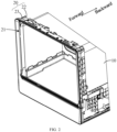
FIG. 1 is a schematic structural view of an embodiment of a dishwasher according to the present disclosure; -
FIG. 2 is a partial schematic view of an embodiment of a tub and a frame according to the present disclosure; -
FIG. 3 is a schematic cross-sectional view of an embodiment of a dishwasher according to the present disclosure; -
FIG. 4 is a partial enlarged view at A inFIG. 3 ; -
FIG. 5 is a schematic view of a door body in a closed state inFIG. 4 ; and -
FIG. 6 is a schematic structural view of another embodiment of a dishwasher of the present disclosure. -
Table one Numerals Name Numerals Name Numerals Name 10 tub 20 frame 21 sealing groove 30 door body 22 supporting frame strip 23 fitting frame strip 31 outer door 32 inner door 231 abutting rib 232 locating edge 11 through hole 221 fixing hole 12 reinforcement flange 40 casing 50 lock - The implementation, functional characteristics, and advantages of the present disclosure will be further described with reference to the drawings.
- Reference will be made clearly and completely technical solutions in the embodiments of the present disclosure with accompanying drawings. Obviously, the embodiments described here are only part, rather than all, of the embodiments of the present disclosure. Based on the embodiments of the present disclosure, other embodiments obtained by those of ordinary skill in the art without creative labor are within the scope of the present disclosure.
- It should be noted that the technical solutions between the various embodiments may be combined with each other, but must be based on those of ordinary skill in the art being capable of realizing it. When the combination of the technical solutions is contradictory or cannot be implemented, it should be considered that the combination of the technical solutions does not exist, nor is within the scope of the present disclosure.
- The present disclosure provides a dishwasher.
- According to the embodiments of the present disclosure, as illustrated in
FIG. 1 to FIG. 5 , the dishwasher includes: atub 10, aframe 20, and adoor body 30. Thetub 10 has an accommodation cavity, and the accommodation cavity has an opening facing forward. Theframe 20 is connected to an outer surface of thetub 10, and arranged along an edge of the opening of the accommodation cavity. In addition, asealing groove 21 is defined in theframe 20, or thesealing groove 21 is enclosed by theframe 20 and the edge of the opening of thetub 10. A sealing strip is disposed in the sealinggroove 21. Thedoor body 30 is configured to expose or cover the opening of the accommodation cavity. Thedoor body 30 abuts against the sealing strip in response to the opening of the accommodation cavity being covered by thedoor body 30. - In the embodiment, a bowl basket may be disposed in the accommodation cavity, and is configured to carry tableware. In addition, a spray arm may also be disposed in the accommodation cavity to spray a fluid towards the bowl basket for cleaning the tableware. The spray arm may be disposed at both an upper part and a lower part of the bowl basket to spray the fluid in several directions. The opening of the accommodation cavity faces forward. The
door body 30 is disposed on a front side of thetub 10. It should be noted that the terms "front" and "rear" refers to a relative direction, and a side where the opening of thetub 10 is located is defined as the front side. Thedoor body 30 and thetub 10 may be rotatably connected to each other. For example, a bottom of thedoor body 30 is rotatably connected to thetub 10. In addition, in other embodiments, other connection manners may also be adopted between thedoor body 30 and thetub 10, which is not limited in the embodiments of the present disclosure. - The
frame 20 may be connected to an inner surface or the outer surface of thetub 10, which is not limited herein. Theframe 20 is located adjacent to the edge of the opening and extends in a length direction adjacent to the edge of the opening. For example, the opening is enclosed by three side walls. Thedoor body 30 is rotatably connected to an edge of a bottom side wall. Theframe 20 extends along edges of the three side walls. A specific structure of theframe 20 is not limited herein, as long as the sealinggroove 21 can be defined in theframe 20. The sealinggroove 21 may be formed by theframe 20 itself, or may be enclosed by theframe 20 and side walls of thetub 10, which is not limited herein, as long as the sealinggroove 21 is opened forwards. For example, the sealinggroove 21 is directly defined in theframe 20 and extends in a length direction of theframe 20. - The sealing strip is embedded in the sealing
groove 21. The sealing strip may be made of a foaming material to improve sealing performance when fitting with the sealinggroove 21 and sealing performance when abutting against thedoor body 30. A front end of the sealing strip may protrude from the opening of the sealinggroove 21 to ensure that thedoor body 30 is in effective contact with the sealing strip. After thedoor body 30 abuts against the sealing strip, a sealing fitting between thedoor body 30 and thetub 10 may be achieved to avoid fluid or air leakage during an operation of the dishwasher. Theframe 20 may be configured as a plastic frame, which may be formed by injection molding. In this way, it is possible to improve production efficiency and reduce production costs. Compared with directly bending the edge of the opening of the tub to form the groove structure, production and processing of theframe 20 is simpler and more convenient. Thus, a structure of thetub 10 can be simplified through forming the sealinggroove 21 by theframe 20 to improve production and processing efficiency of the dishwasher. - According to the dishwasher of the present disclosure, the
frame 20 is arranged at the edge of the opening of thetub 10 to form the sealinggroove 21 by theframe 20 or form the sealinggroove 21 by enclosing theframe 20 and the side walls of thetub 10. Further, the sealing strip is disposed in the sealinggroove 21. Therefore, in response to the opening of the accommodation cavity being covered by thedoor body 30, thedoor body 30 can abut against the sealing strip to realize the sealing fitting between thedoor body 30 and thetub 10. The sealinggroove 21 is formed by theframe 20 or is formed by enclosing theframe 20 and thetub 10. Therefore, the structure of thetub 10 can be effectively simplified to reduce production difficulty and improve processing efficiency. - It should be noted that, directional indication (such as upper, lower, left, right, front, and back, ...) related to the embodiments of the present disclosure is only intended to interpret a relative positional relationship and a motion situation between each component in a certain specific attitude (as illustrated in
FIG. 1 ). When the specific attitude changes, the directional indication also changes accordingly. - In some embodiments, as illustrated in
FIG. 4 andFIG. 5 , theframe 20 includes a supportingframe strip 22 abutting against the outer surface of thetub 10, and afitting frame strip 23 connected to a front side wall of the supportingframe strip 22. Thefitting frame strip 23 is spaced apart from the outer surface of thetub 10. The edge of the opening of thetub 10 protrudes from the front side wall of the supportingframe strip 22. The sealinggroove 21 is located between thefitting frame strip 23 and the edge of the opening of thetub 10. In the embodiment, theframe 20 is connected to the outer surface of thetub 10, which can reduce occupation of a space of the accommodation cavity. When a frame strip is located on a top wall of thetub 10, a bottom wall of the supportingframe strip 22 protrudes from a bottom wall of thefitting frame strip 23, and abuts against thetub 10. The edge of the opening protrudes forwardly from the front side wall of the supportingframe strip 22 to enclose together with the bottom wall of thefitting frame strip 23 to form the sealinggroove 21. The sealinggroove 21 is configured to be formed by enclosing theframe 20 and the outer surface of thetub 10, which enables a sealing portion to be closer to thetub 10 after the sealing strip is disposed within the sealinggroove 21. Therefore, it is possible to prevent the fluid sprayed to thedoor body 30 from flowing to theframe 20 to further improve the sealing performance. - In practical application, as illustrated in
FIG. 1 ,FIG. 4 andFIG. 5 , thedoor body 30 includes anouter door 31, and aninner door 32 facing towards an inner surface of theouter door 31. Theinner door 32 abuts against the sealing strip in response to the opening of the accommodation cavity is covered by thedoor body 30. In the embodiment, theinner door 32 may have a frame shape. Three sides of the frame of theinner door 32 are adjacent to a top side and two vertical side of theouter door 31, respectively. That is, theinner door 32 protrudes from a middle part of thedoor body 30. Therefore, it is possible to prevent thedoor body 30 from being normally closed when too much tableware protrudes out of the opening of the accommodation cavity. Meanwhile, it is also ensured that theinner door 32 can effectively abut against the sealing strip to increase sealing stability. - In addition, as illustrated in
FIG.4 andFIG. 5 , a periphery of theinner door 32 abuts against the sealing strip. A front side wall of thefitting frame strip 23 protrudes from the edge of the opening of thetub 10. In the embodiment, when theinner door 32 abuts against the sealing strip, a part of thefitting frame strip 23 protruding from the opening of thetub 10 is arranged around a peripheral side of theinner door 32. Thus, it is possible to provide a hidden and protection for an abutting position between theinner door 32 and the sealing strip, and thus the sealing stability is improved. - In one embodiment, as illustrated in
FIG. 4 , anabutting rib 231 is disposed on, and protrudes from an end, facing away from the sealinggroove 21, of a front side wall of thefitting frame strip 23. A front end of theabutting rib 231 is bent outwards to form a locatingedge 232. The dishwasher further includes acasing 40. Thecasing 40 has an opening facing forward. Thetub 10 is arranged in thecasing 40. An edge of the opening of thecasing 40 abuts against the locatingedge 232. In the embodiment, the supportingframe strip 22 and thefitting frame strip 23 are located between thetub 10 and thecasing 40, which can provide supporting for thecasing 40, and maintain stable shapes of the openings of thecasing 40 and thetub 10 to prevent collapse occurred at the openings. Theabutting rib 231 and the locatingedge 232 both extend in a length direction of thefitting frame strip 23. An inner surface of thecasing 40 abuts against an outer surface of theabutting rib 231, and a front end of the opening of thecasing 40 abuts against a rear surface of the locatingedge 232. In addition, an outer edge of the locatingedge 232 may be flush with an outer surface of thecasing 40. Therefore, it is possible to enhance the fitting strength of thecasing 40 and theframe 20, and improve integrity of the dishwasher. - In one embodiment, the
frame 20 is detachably connected to thetub 10. In the embodiment, theframe 20 is connected to thetub 10 by the supportingframe strip 22, and the specific connection manner is not limited herein, as long as theframe 20 can be detachably connected to thetub 10. For example, theframe 20 may be snapped to thetub 10. By detachably connecting theframe 20 to thetub 10, detachment and replacement of theframe 20 are facilitated. In some embodiments, as illustrated inFIG. 4 , a throughhole 11 is defined on a side wall of thetub 10. The supportingframe strip 22 has a fixinghole 221 corresponding to the throughhole 11. The throughhole 11 and the fixinghole 221 are connected to each other by a fastener. In the embodiment, thetub 10 and theframe 20 may be locked by a screw to realize the detachable connection. When detaching or mounting theframe 20, the fastener may be detached from or mounted to the accommodation cavity of thetub 10. Therefore, theframe 20 and thetub 10 may be detached or mounted more simply and conveniently. - In the practical application, as illustrated in
FIG. 4 , the edge of the opening of thetub 10 is bent backwards to form areinforcement flange 12. In the embodiment, by thereinforcement flange 12, it is possible to improve the structural strength of the opening of thetub 10, and maintain the stable shape of the opening to avoid collapse. Further, it is also possible to prevent use's hand from being scrapped to improve user experience. - In one embodiment, as illustrated in
FIG. 6 , theframe 20 has alock 50 configured to lock or unlock thedoor body 30. In the embodiment, thelock 50 may be in a wax motor form. When thedoor body 30 is required to be opened, the wax motor is powered and heated to push thedoor body 30 to open thedoor body 30. Theframe 20 may be provided with a limiting groove. The limiting groove may be a groove having a continuous and complete groove wall, or may be formed by enclosing a plurality of limiting ribs arranged at intervals. Thelock 50 is at least partially disposed in the limiting groove. A part of thelock 50 disposed in the limiting groove is limited by theframe 20. Theframe 20 abuts against and thelock 50 and limits thedoor body 50 in several directions to prevent separation of thelock 50 from thetub 10. In some embodiments, when the bottom of thedoor body 30 is rotatably connected to thetub 10, thelock 50 may be located above a top wall of thetub 10 to push a top of thedoor body 30 to open thedoor body 30. Therefore, torque can be increased to enable thelock 50 to lock or unlock thedoor body 30 more smoothly and conveniently. - The above illustrates merely preferable embodiments of the present disclosure, rather than being intended to limit the scope of the present disclosure. According to the inventive concept of the present disclosure, any equivalent structural modification made by using the description and accompanying drawings of the present disclosure, or directly/indirectly application in other related art, are both included within the scope of the present disclosure.
- Alternative embodiments are set out in the following clauses.
- 1. A dishwasher, comprising:
- a tub having an accommodation cavity, the accommodation cavity having an opening facing forward;
- a frame connected to an outer surface of the tub and arranged along an edge of the opening of the accommodation cavity, wherein a sealing groove is defined in the frame, or the sealing groove is enclosed by the frame and the edge of the opening of the tub, and wherein a sealing strip is disposed in the sealing groove; and
- a door body configured to expose or cover the opening of the accommodation cavity, wherein the door body abuts against the sealing strip in response to the opening of the accommodation cavity being covered by the door body.
- 2. The dishwasher according to clause 1, wherein the frame comprises:
- a supporting frame strip abutting against the outer surface of the tub; and
- a fitting frame strip connected to a front side wall of the supporting frame strip and spaced apart from the outer surface of the tub, wherein:
- the edge of the opening of the tub protrudes from the front side wall of the supporting frame strip; and
- the sealing groove is located between the matching frame strip and the edge of the opening of the tub.
- 3. The dishwasher according to clause 2, wherein:
- the door body comprises an outer door, and an inner door facing towards an inner surface of the outer door;
- the inner door abuts against the sealing strip in response to the opening of the accommodation cavity being covered by the door body.
- 4. The dishwasher according to clause 3, wherein:
- a periphery of the inner door abuts against the sealing strip; and
- a front side wall of the matching frame strip protrudes from the edge of the opening of the tub.
- 5. The dishwasher according to clause 2, wherein:
- an abutting rib is disposed on and protrudes from an end, facing away from the sealing groove, of a front side wall of the matching frame strip, a front end of the abutting rib being bent outwards to form a locating edge;
- the dishwasher further comprises a casing with an opening facing forward;
- the tub is arranged in the casing; and
- an edge of the opening of the casing abuts against the locating edge.
- 6. The dishwasher according to clause 2, wherein the frame is detachably connected to the tub.
- 7. The dishwasher according to clause 6, wherein:
- a side wall of the tub has a through hole;
- the supporting frame strip has a fixing hole corresponding to the through hole; and
- the through hole and the fixing hole are connected to each other by a fastener.
- 8. The dishwasher according to clause 1, wherein the edge of the opening of the tub is bent backwards to form a reinforcement flange.
- 9. The dishwasher according to clause 1, wherein the frame has a lock configured to lock or unlock the door body.
- 10. The dishwasher according to any one of clauses 1 to 9, wherein the frame is configured as a plastic frame.
Claims (15)
- A dishwasher, comprising:a tub (10) having an accommodation cavity, the accommodation cavity having an opening facing forward;a frame (20) connected to an outer surface of the tub (10) and arranged along an edge of the opening of the accommodation cavity, wherein a sealing groove (21) is defined in the frame (20), or the sealing groove (21) is enclosed by the frame (20) and the edge of the opening of the tub (10), and wherein a sealing strip is disposed in the sealing groove (21); anda door body (30) configured to expose or cover the opening of the accommodation cavity, wherein the door body (30) abuts against the sealing strip in response to the opening of the accommodation cavity being covered by the door body (30).
- The dishwasher according to claim 1, wherein the sealing groove (21) is directly defined in the frame (20) and extends in a length direction of the frame (20).
- The dishwasher according to claim 1 or 2, wherein a front end of the sealing strip protrudes from the opening of the sealing groove (21) to ensure that the door body (30) is in effective contact with the sealing strip.
- The dishwasher according to any one of claims 1 to 3, wherein the sealing strip is embedded in the sealing groove (21).
- The dishwasher according to any one of claims 1 to 4, wherein the sealing strip is made of a foaming material.
- The dishwasher according to claim 1, wherein the frame (20) comprises:a supporting frame strip (22) abutting against the outer surface of the tub (10); anda fitting frame strip (23) connected to a front side wall of the supporting frame strip (22) and spaced apart from the outer surface of the tub (10), wherein:the edge of the opening of the tub (10) protrudes from the front side wall of the supporting frame strip (22); andthe sealing groove (21) is located between the matching frame strip and the edge of the opening of the tub (10).
- The dishwasher according to claim 6, wherein:the door body (30) comprises an outer door (31), and an inner door (32) facing towards an inner surface of the outer door (31);the inner door (32) abuts against the sealing strip in response to the opening of the accommodation cavity being covered by the door body (30).
- The dishwasher according to claim 7, wherein:a periphery of the inner door (32) abuts against the sealing strip; anda front side wall of the matching frame strip protrudes from the edge of the opening of the tub (10).
- The dishwasher according to claim 8, wherein when the inner door (32) abuts against the sealing strip, a part of the fitting frame strip (23) protruding from the opening of the tub (10) is arranged around a peripheral side of the inner door (32).
- The dishwasher according to claim 6, wherein:an abutting rib (231) is disposed on and protrudes from an end, facing away from the sealing groove (21), of a front side wall of the matching frame strip, a front end of the abutting rib (231) being bent outwards to form a locating edge (232);the dishwasher further comprises a casing (40) with an opening facing forward;the tub (10) is arranged in the casing (40); andan edge of the opening of the casing (40) abuts against the locating edge (232).
- The dishwasher according to claim 6, wherein the frame (20) is detachably connected to the tub (10).
- The dishwasher according to claim 10, wherein:a side wall of the tub (10) has a through hole (11);the supporting frame strip (22) has a fixing hole (221) corresponding to the through hole (11); andthe through hole (11) and the fixing hole (221) are connected to each other by a fastener.
- The dishwasher according to claim 1, wherein the edge of the opening of the tub (10) is bent backwards to form a reinforcement flange (12).
- The dishwasher according to claim 1, wherein the frame (20) has a lock (50) configured to lock or unlock the door body (30).
- The dishwasher according to any one of claims 1 to 14, wherein the frame (20) is configured as a plastic frame.
Applications Claiming Priority (3)
| Application Number | Priority Date | Filing Date | Title |
|---|---|---|---|
| CN202020610489.5U CN212307758U (en) | 2020-04-21 | 2020-04-21 | dishwasher |
| EP21792659.1A EP4140384B1 (en) | 2020-04-21 | 2021-04-01 | Dishwasher |
| PCT/CN2021/085092 WO2021213173A1 (en) | 2020-04-21 | 2021-04-01 | Dishwasher |
Related Parent Applications (2)
| Application Number | Title | Priority Date | Filing Date |
|---|---|---|---|
| EP21792659.1A Division EP4140384B1 (en) | 2020-04-21 | 2021-04-01 | Dishwasher |
| EP21792659.1A Division-Into EP4140384B1 (en) | 2020-04-21 | 2021-04-01 | Dishwasher |
Publications (4)
| Publication Number | Publication Date |
|---|---|
| EP4442183A2 true EP4442183A2 (en) | 2024-10-09 |
| EP4442183A3 EP4442183A3 (en) | 2025-01-15 |
| EP4442183C0 EP4442183C0 (en) | 2026-01-21 |
| EP4442183B1 EP4442183B1 (en) | 2026-01-21 |
Family
ID=74032624
Family Applications (2)
| Application Number | Title | Priority Date | Filing Date |
|---|---|---|---|
| EP21792659.1A Active EP4140384B1 (en) | 2020-04-21 | 2021-04-01 | Dishwasher |
| EP24195614.3A Active EP4442183B1 (en) | 2020-04-21 | 2021-04-01 | Dishwasher |
Family Applications Before (1)
| Application Number | Title | Priority Date | Filing Date |
|---|---|---|---|
| EP21792659.1A Active EP4140384B1 (en) | 2020-04-21 | 2021-04-01 | Dishwasher |
Country Status (8)
| Country | Link |
|---|---|
| US (2) | US12102280B2 (en) |
| EP (2) | EP4140384B1 (en) |
| JP (1) | JP7403002B2 (en) |
| KR (2) | KR102698226B1 (en) |
| CN (1) | CN212307758U (en) |
| ES (1) | ES2990018T3 (en) |
| PL (1) | PL4140384T3 (en) |
| WO (1) | WO2021213173A1 (en) |
Families Citing this family (5)
| Publication number | Priority date | Publication date | Assignee | Title |
|---|---|---|---|---|
| CN212307758U (en) | 2020-04-21 | 2021-01-08 | 佛山市顺德区美的洗涤电器制造有限公司 | dishwasher |
| CN112826415B (en) * | 2021-01-22 | 2022-05-17 | 佛山市顺德区美的洗涤电器制造有限公司 | dishwasher |
| KR20230018765A (en) * | 2021-07-30 | 2023-02-07 | 삼성전자주식회사 | Dish washer |
| CN116687304A (en) * | 2022-02-25 | 2023-09-05 | 佛山市顺德区美的洗涤电器制造有限公司 | Household appliance |
| JP7827378B2 (en) * | 2022-08-18 | 2026-03-10 | 蕪湖美的智能厨電制造有限公司 | Door locks and dishwashers |
Family Cites Families (15)
| Publication number | Priority date | Publication date | Assignee | Title |
|---|---|---|---|---|
| US3443719A (en) * | 1968-03-25 | 1969-05-13 | Design & Mfg Corp | Gasket for front opening dishwashing machines |
| CA1333987C (en) * | 1989-02-08 | 1995-01-17 | Jean Archambault | Gasketless door for dishwashers |
| KR100234102B1 (en) * | 1997-12-08 | 1999-12-15 | 윤종용 | Dishwasher with gasket |
| DE102005028449B4 (en) * | 2005-06-17 | 2007-03-08 | Miele & Cie. Kg | Dishwasher with a washing container, which can be closed by a door, and method for performing a washing program in such a dishwasher |
| JP4544344B2 (en) * | 2008-05-19 | 2010-09-15 | パナソニック株式会社 | dishwasher |
| US8118947B2 (en) | 2008-05-20 | 2012-02-21 | Electrolux Home Products, Inc. | Sealing device for a dishwasher, and associated apparatus and method |
| JP4893785B2 (en) * | 2009-07-08 | 2012-03-07 | パナソニック株式会社 | dishwasher |
| DE102011003821B4 (en) * | 2011-02-08 | 2016-06-09 | BSH Hausgeräte GmbH | Dishwasher, in particular household dishwasher |
| WO2017171215A1 (en) * | 2016-03-28 | 2017-10-05 | Lg Electronics Inc. | Lock and home appliance having the same |
| CN209331980U (en) | 2018-08-31 | 2019-09-03 | 杭州小月亮科技有限公司 | A kind of dish-washing machine of good airproof performance |
| CN209074491U (en) | 2018-10-11 | 2019-07-09 | 佛山市云米电器科技有限公司 | A kind of door sealing structure and the dish-washing machine using it |
| CN109171586A (en) | 2018-10-11 | 2019-01-11 | 佛山市云米电器科技有限公司 | A kind of dish-washing machine easy to clean |
| KR102766431B1 (en) * | 2019-08-29 | 2025-02-12 | 삼성전자주식회사 | Dishwasher |
| CN212307758U (en) * | 2020-04-21 | 2021-01-08 | 佛山市顺德区美的洗涤电器制造有限公司 | dishwasher |
| CN212307768U (en) * | 2020-04-21 | 2021-01-08 | 佛山市顺德区美的洗涤电器制造有限公司 | dishwasher |
-
2020
- 2020-04-21 CN CN202020610489.5U patent/CN212307758U/en active Active
-
2021
- 2021-04-01 EP EP21792659.1A patent/EP4140384B1/en active Active
- 2021-04-01 EP EP24195614.3A patent/EP4442183B1/en active Active
- 2021-04-01 PL PL21792659.1T patent/PL4140384T3/en unknown
- 2021-04-01 JP JP2022564639A patent/JP7403002B2/en active Active
- 2021-04-01 ES ES21792659T patent/ES2990018T3/en active Active
- 2021-04-01 KR KR1020227040671A patent/KR102698226B1/en active Active
- 2021-04-01 KR KR1020247027639A patent/KR20240131456A/en active Pending
- 2021-04-01 WO PCT/CN2021/085092 patent/WO2021213173A1/en not_active Ceased
-
2022
- 2022-10-21 US US17/970,985 patent/US12102280B2/en active Active
-
2024
- 2024-08-29 US US18/820,080 patent/US20240415365A1/en active Pending
Also Published As
| Publication number | Publication date |
|---|---|
| PL4140384T3 (en) | 2025-02-10 |
| JP7403002B2 (en) | 2023-12-21 |
| EP4140384A4 (en) | 2023-10-18 |
| US20230078420A1 (en) | 2023-03-16 |
| CN212307758U (en) | 2021-01-08 |
| EP4140384A1 (en) | 2023-03-01 |
| KR102698226B1 (en) | 2024-08-22 |
| EP4442183C0 (en) | 2026-01-21 |
| EP4140384C0 (en) | 2024-09-25 |
| EP4442183B1 (en) | 2026-01-21 |
| KR20240131456A (en) | 2024-08-30 |
| JP2023523049A (en) | 2023-06-01 |
| KR20230002931A (en) | 2023-01-05 |
| US20240415365A1 (en) | 2024-12-19 |
| US12102280B2 (en) | 2024-10-01 |
| EP4140384B1 (en) | 2024-09-25 |
| WO2021213173A1 (en) | 2021-10-28 |
| ES2990018T3 (en) | 2024-11-28 |
| EP4442183A3 (en) | 2025-01-15 |
Similar Documents
| Publication | Publication Date | Title |
|---|---|---|
| EP4140384B1 (en) | Dishwasher | |
| CN106133231A (en) | Washing machine | |
| CN108742430A (en) | Liner component and dish-washing machine | |
| CN108742411A (en) | Liner component and dish-washing machine | |
| CN212307768U (en) | dishwasher | |
| CN211834275U (en) | Door body sealing structure of water tank dish washing machine | |
| CN216308349U (en) | Box clamping structure | |
| CN216823357U (en) | Handle device and dish-washing machine | |
| CN214033053U (en) | Washing machine | |
| CN115404664B (en) | A wall-mounted clothing handling device and its front sealing assembly | |
| CN111839411B (en) | Dishwasher door baffle structure and dishwasher | |
| CN108577732A (en) | Dish washer display control panel and door plant cooperation structure and dish washer thereof | |
| CN221533648U (en) | Door body structure of dish washer and dish washer | |
| CN108670161B (en) | Control panel box and dishwasher | |
| CN209048064U (en) | Dish-washing machine | |
| CN218606525U (en) | Dish washing machine | |
| CN201719216U (en) | Inner container bead and embedded dish washer with same | |
| CN209122125U (en) | Electrically-controlled component and dish-washing machine for dish-washing machine | |
| CN222210427U (en) | Kitchen steaming and baking integrated machine | |
| CN222885352U (en) | Dish washer | |
| CN217338491U (en) | Dish washer door body group spare and dish washer | |
| CN209437189U (en) | A kind of drawer dishwasher liner | |
| CN110269571A (en) | A kind of door body assembly and dish-washing machine | |
| CN213113982U (en) | Plastic observation window outer frame convenient for hinge installation for washing machine | |
| CN210446950U (en) | Inner container and dish washing machine |
Legal Events
| Date | Code | Title | Description |
|---|---|---|---|
| PUAI | Public reference made under article 153(3) epc to a published international application that has entered the european phase |
Free format text: ORIGINAL CODE: 0009012 |
|
| STAA | Information on the status of an ep patent application or granted ep patent |
Free format text: STATUS: THE APPLICATION HAS BEEN PUBLISHED |
|
| AC | Divisional application: reference to earlier application |
Ref document number: 4140384 Country of ref document: EP Kind code of ref document: P |
|
| AK | Designated contracting states |
Kind code of ref document: A2 Designated state(s): AL AT BE BG CH CY CZ DE DK EE ES FI FR GB GR HR HU IE IS IT LI LT LU LV MC MK MT NL NO PL PT RO RS SE SI SK SM TR |
|
| REG | Reference to a national code |
Ref country code: DE Ref legal event code: R079 Free format text: PREVIOUS MAIN CLASS: A47L0015420000 Ipc: A47L0015140000 Ref document number: 602021046576 Country of ref document: DE |
|
| PUAL | Search report despatched |
Free format text: ORIGINAL CODE: 0009013 |
|
| AK | Designated contracting states |
Kind code of ref document: A3 Designated state(s): AL AT BE BG CH CY CZ DE DK EE ES FI FR GB GR HR HU IE IS IT LI LT LU LV MC MK MT NL NO PL PT RO RS SE SI SK SM TR |
|
| RIC1 | Information provided on ipc code assigned before grant |
Ipc: A47L 15/42 20060101ALI20241210BHEP Ipc: A47L 15/14 20060101AFI20241210BHEP |
|
| STAA | Information on the status of an ep patent application or granted ep patent |
Free format text: STATUS: REQUEST FOR EXAMINATION WAS MADE |
|
| 17P | Request for examination filed |
Effective date: 20250423 |
|
| GRAP | Despatch of communication of intention to grant a patent |
Free format text: ORIGINAL CODE: EPIDOSNIGR1 |
|
| STAA | Information on the status of an ep patent application or granted ep patent |
Free format text: STATUS: GRANT OF PATENT IS INTENDED |
|
| INTG | Intention to grant announced |
Effective date: 20251016 |
|
| GRAS | Grant fee paid |
Free format text: ORIGINAL CODE: EPIDOSNIGR3 |
|
| GRAA | (expected) grant |
Free format text: ORIGINAL CODE: 0009210 |
|
| STAA | Information on the status of an ep patent application or granted ep patent |
Free format text: STATUS: THE PATENT HAS BEEN GRANTED |
|
| AC | Divisional application: reference to earlier application |
Ref document number: 4140384 Country of ref document: EP Kind code of ref document: P |
|
| AK | Designated contracting states |
Kind code of ref document: B1 Designated state(s): AL AT BE BG CH CY CZ DE DK EE ES FI FR GB GR HR HU IE IS IT LI LT LU LV MC MK MT NL NO PL PT RO RS SE SI SK SM TR |
|
| REG | Reference to a national code |
Ref country code: CH Ref legal event code: F10 Free format text: ST27 STATUS EVENT CODE: U-0-0-F10-F00 (AS PROVIDED BY THE NATIONAL OFFICE) Effective date: 20260121 |
|
| REG | Reference to a national code |
Ref country code: DE Ref legal event code: R096 Ref document number: 602021046576 Country of ref document: DE |
|
| REG | Reference to a national code |
Ref country code: IE Ref legal event code: FG4D |
|
| U01 | Request for unitary effect filed |
Effective date: 20260203 |
|
| U07 | Unitary effect registered |
Designated state(s): AT BE BG DE DK EE FI FR IT LT LU LV MT NL PT RO SE SI Effective date: 20260209 |
|
| U20 | Renewal fee for the european patent with unitary effect paid |
Year of fee payment: 6 Effective date: 20260218 |
|
| PGFP | Annual fee paid to national office [announced via postgrant information from national office to epo] |
Ref country code: GB Payment date: 20260218 Year of fee payment: 6 |
|
| U1N | Appointed representative for the unitary patent procedure changed after the registration of the unitary effect |
Representative=s name: TREEBY, PHILIP DAVID WILLIAM; GB |
|
| PG25 | Lapsed in a contracting state [announced via postgrant information from national office to epo] |
Ref country code: RS Free format text: LAPSE BECAUSE OF FAILURE TO SUBMIT A TRANSLATION OF THE DESCRIPTION OR TO PAY THE FEE WITHIN THE PRESCRIBED TIME-LIMIT Effective date: 20260421 |
|
| PG25 | Lapsed in a contracting state [announced via postgrant information from national office to epo] |
Ref country code: ES Free format text: LAPSE BECAUSE OF FAILURE TO SUBMIT A TRANSLATION OF THE DESCRIPTION OR TO PAY THE FEE WITHIN THE PRESCRIBED TIME-LIMIT Effective date: 20260121 |
|
| PG25 | Lapsed in a contracting state [announced via postgrant information from national office to epo] |
Ref country code: PL Free format text: LAPSE BECAUSE OF FAILURE TO SUBMIT A TRANSLATION OF THE DESCRIPTION OR TO PAY THE FEE WITHIN THE PRESCRIBED TIME-LIMIT Effective date: 20260121 |
|
| PG25 | Lapsed in a contracting state [announced via postgrant information from national office to epo] |
Ref country code: GR Free format text: LAPSE BECAUSE OF FAILURE TO SUBMIT A TRANSLATION OF THE DESCRIPTION OR TO PAY THE FEE WITHIN THE PRESCRIBED TIME-LIMIT Effective date: 20260422 |
|
| PG25 | Lapsed in a contracting state [announced via postgrant information from national office to epo] |
Ref country code: NO Free format text: LAPSE BECAUSE OF FAILURE TO SUBMIT A TRANSLATION OF THE DESCRIPTION OR TO PAY THE FEE WITHIN THE PRESCRIBED TIME-LIMIT Effective date: 20260421 |
|
| PG25 | Lapsed in a contracting state [announced via postgrant information from national office to epo] |
Ref country code: HR Free format text: LAPSE BECAUSE OF FAILURE TO SUBMIT A TRANSLATION OF THE DESCRIPTION OR TO PAY THE FEE WITHIN THE PRESCRIBED TIME-LIMIT Effective date: 20260121 |
|
| PG25 | Lapsed in a contracting state [announced via postgrant information from national office to epo] |
Ref country code: IS Free format text: LAPSE BECAUSE OF FAILURE TO SUBMIT A TRANSLATION OF THE DESCRIPTION OR TO PAY THE FEE WITHIN THE PRESCRIBED TIME-LIMIT Effective date: 20260521 |