EP4442131A1 - Seam inspection device and seam inspection method for cigarette filter - Google Patents
Seam inspection device and seam inspection method for cigarette filter Download PDFInfo
- Publication number
- EP4442131A1 EP4442131A1 EP21966308.5A EP21966308A EP4442131A1 EP 4442131 A1 EP4442131 A1 EP 4442131A1 EP 21966308 A EP21966308 A EP 21966308A EP 4442131 A1 EP4442131 A1 EP 4442131A1
- Authority
- EP
- European Patent Office
- Prior art keywords
- filter
- seam
- rod
- manufacturing device
- unit
- Prior art date
- Legal status (The legal status is an assumption and is not a legal conclusion. Google has not performed a legal analysis and makes no representation as to the accuracy of the status listed.)
- Pending
Links
Images


Classifications
-
- A—HUMAN NECESSITIES
- A24—TOBACCO; CIGARS; CIGARETTES; SIMULATED SMOKING DEVICES; SMOKERS' REQUISITES
- A24D—CIGARS; CIGARETTES; TOBACCO SMOKE FILTERS; MOUTHPIECES OF CIGARS OR CIGARETTES; MANUFACTURE OF TOBACCO SMOKE FILTERS OR MOUTHPIECES
- A24D3/00—Tobacco smoke filters, e.g. filter tips or filtering inserts; Filters specially adapted for simulated smoking devices; Mouthpieces of cigars or cigarettes
- A24D3/02—Manufacture of tobacco smoke filters
-
- A—HUMAN NECESSITIES
- A24—TOBACCO; CIGARS; CIGARETTES; SIMULATED SMOKING DEVICES; SMOKERS' REQUISITES
- A24C—MACHINES FOR MAKING CIGARS OR CIGARETTES
- A24C5/00—Making cigarettes; Making tipping materials for, or attaching filters or mouthpieces to, cigars or cigarettes
- A24C5/32—Separating, ordering, counting or examining cigarettes; Regulating the feeding of tobacco according to rod or cigarette condition
- A24C5/34—Examining cigarettes or the rod, e.g. for regulating the feeding of tobacco; Removing defective cigarettes
- A24C5/3412—Examining cigarettes or the rod, e.g. for regulating the feeding of tobacco; Removing defective cigarettes by means of light, radiation or electrostatic fields
-
- A—HUMAN NECESSITIES
- A24—TOBACCO; CIGARS; CIGARETTES; SIMULATED SMOKING DEVICES; SMOKERS' REQUISITES
- A24D—CIGARS; CIGARETTES; TOBACCO SMOKE FILTERS; MOUTHPIECES OF CIGARS OR CIGARETTES; MANUFACTURE OF TOBACCO SMOKE FILTERS OR MOUTHPIECES
- A24D3/00—Tobacco smoke filters, e.g. filter tips or filtering inserts; Filters specially adapted for simulated smoking devices; Mouthpieces of cigars or cigarettes
- A24D3/02—Manufacture of tobacco smoke filters
- A24D3/0295—Process control means
Definitions
- the present invention relates to a seam inspection device and a seam inspection method for a tobacco filter.
- a tobacco filter (a filter rod) formed by a filter manufacturing device includes a rod member formed by a filter material, and a paper web (rolling paper) enveloping the rod member. More specifically, the filter rod is formed by forming a filter rod continuum by wrapping the paper web around the rod member and gluing an overlapped part of the paper web, and then, cutting the filter rod continuum into a predetermined length.
- the paper web here has a finite length.
- a plurality (such as two) of paper webs having a finite length are installed on the filter manufacturing device in a state of being wound around bobbins, and a terminal end of the paper web on one bobbin and a start end of the paper web on the other bobbin are spliced with a seal or the like by a rolling paper supply unit such that the paper web is continuously supplied.
- the filter rod may be continuously manufactured.
- a filter inspection device performs defect inspection on the filter rod that is cut into a predetermined length. More specifically, inspection is performed with respect to a segment length of the filter rod, presence/absence of damage, and the like, and a filter rod that is determined to be defective is removed by a removing unit.
- a filter rod including a seam of the paper webs is desirably appropriately removed by the removing unit so that the filter rod including the seam does not flow to processes at a later stage.
- a conventional filter inspection device removes a filter rod by a removing unit with seam detection at a rolling paper supply unit as a trigger. More specifically, a sensor for detecting a seam of paper webs is provided near the rolling paper supply unit, and the sensor outputs a seam detection signal when detecting a seam of paper webs that are supplied by the rolling paper supply unit. The removing unit removes a bundle of filter rods in a predetermined range including the seam of the paper webs according to the seam detection signal, at a timing when the filter rods pass the removing unit.
- the filter rod including the seam of the paper webs is possibly not appropriately removed due to erroneous operation of the removing unit or the like.
- the removing unit does not include a function of stopping the filter manufacturing device. Accordingly, an operator has to visually check whether the removed filter rod includes the seam of the paper webs, and the operator has to stop the filter manufacturing device as necessary.
- a knife mechanism of the filter manufacturing device for cutting a filter rod continuum into a predetermined length is not synchronized with the seam detection signal. Accordingly, for example, when a filter rod continuum is cut at the seam of the paper webs, if the length of the seam is 19 mm, a filter rod including 18 mm of seam and a filter rod including 1 mm of seam are possibly cut. In such a case, it is difficult for the operator to check whether the filter rod including 1 mm of seam is removed or not.
- an inspection system for determining, during a manufacturing process of the filter rod, whether a filter rod continuum is cut at a desired position or not, and for adjusting a position of a cutting device in a case where it is determined that cutting is performed too early or too late (for example, see PTL 1).
- the inspection system of PTL 1 is for determining, in the manufacturing process of the filter rod, whether a filter rod continuum is cut at a desired position or not, and is not capable of detecting whether a removed filter rod includes a seam of paper webs or not. Moreover, in the case where the position of the cutting device is adjusted, a length of filter rods that are formed may be varied, thereby affecting processes at a later stage.
- the present invention has been made to at least partially solve the problems as described above, and is aimed at achieving a seam inspection device and a seam inspection method for a tobacco filter, with which whether a filter rod including a seam of paper webs is appropriately removed or not can be inspected by detecting whether a removed filter rod includes the seam or not.
- the filter rod removed from the conveying unit by the removing unit is housed in the container, the image capturing unit captures an image of the filter rod housed in the container, and the analysis unit analyzes the image data of the captured filter rod, and the seam of the paper webs is thereby detected. Accordingly, whether a filter rod including the seam of the paper webs is appropriately removed may be inspected by detecting whether a removed filter rod includes the seam.
- a second mode of the present invention according to the first mode further includes a notification unit for outputting a stop signal to the filter manufacturing device in a case where the seam of the paper webs is not detected by the analysis unit.
- the analysis unit detects the seam of the paper webs by performing edge detection on the image data of the filter rod.
- the analysis unit performs edge detection, the seam of the paper webs may be detected with higher accuracy.
- structures for inspecting the filter rod received from the filter manufacturing device may be used for detection of the seam of the paper webs, and thus, structures necessary for detecting the seam of the paper webs may be reduced, and the configuration of the seam inspection device for a tobacco filter may be simplified.
- the seam inspection method for a tobacco filter is a seam inspection method for a tobacco filter that is applied to a filter inspection device for inspecting a filter rod manufactured by a filter manufacturing device, where the filter manufacturing device is for forming filter rods by cutting, into a predetermined length, a filter rod continuum that is formed by wrapping a paper web around a rod member formed by a filter material, where the filter manufacturing device continuously supplies the paper web through successive splicing, the filter inspection device removes a bundle of the filter rods in a predetermined range including a seam of the paper webs by a removing unit based on a seam detection signal input from the filter manufacturing device, from a conveying unit for conveying the filter rod received from the filter manufacturing device, and the seam inspection method includes a housing step for housing, in a container, the filter rod that is removed from the conveying unit, an image capturing step for capturing, by an image capturing unit, an image of the filter rod
- a filter rod removed from the conveying unit by the removing unit is housed in the container in the housing step, the filter rod housed in the container is captured in the image capturing step, and the image data of the captured filter rod is analyzed in the analysis step, and the seam of the paper webs is thereby detected. Accordingly, whether a filter rod including the seam of the paper webs is appropriately removed may be inspected by detecting whether a removed filter rod includes the seam.
- a sixth mode of the present invention according to the fifth mode further includes a notification step for outputting a stop signal to the filter manufacturing device in a case where the seam of the paper webs is not detected in the analysis step.
- the stop signal is output to the filter manufacturing device in the notification step, and the filter manufacturing device may thus be stopped and a filter rod including the seam of the paper webs may be prevented from flowing to processes at a later stage.
- Fig. 1 is a configuration diagram showing a filter manufacturing device according to an embodiment of the present invention.
- a filter manufacturing device 100 roughly includes a tow processing section 10, a forming section 20, a wrapping section 30, a cutting section 40, and a control unit 50.
- the tow processing section 10 includes a bale 11 containing a filter material of cellulose acetate fiber, or in other words, a tow T, and a tow path 12 extends from the bale 11.
- the tow path 12 includes a primary banding jet 13, a guide roller 14, a pair of pre-tensioning rollers 15, a pair of blooming rollers 16, and a secondary banding jet 17 that are sequentially disposed from the bale 11 side, and the secondary banding jet 17 is positioned at a terminal end of the tow path 12.
- the primary banding jet 13 ejects compressed air from the bale 11 side toward the tow T.
- the ejected compressed air opens, or in other words, loosens, the tow T, and moderately stretches crimp of the tow T.
- the guide roller 14 directs a supply direction of the tow T to the pair of pre-tensioning rollers 15, and the tow T passes between the pair of pre-tensioning rollers 15.
- the pair of pre-tensioning rollers 15 presses the opened tow T, applies a predetermined tensile force to the tow T in cooperation with the pair of blooming rollers 16, and further stretches the crimp of the tow T.
- the pair of blooming rollers 16 divides the opened tow T into a plurality of bundles, and supplies the bundles to the secondary banding jet 17.
- the secondary banding jet 17 ejects compressed air toward the divided bundle, and the compressed air opens the divided bundle.
- the divided bundle spreads in a width direction of the tow path 12, and forms a flat filter web WF.
- the filter web WF is fed to the forming section 20.
- the filter web WF fed to the forming section 20 is conveyed toward a trumpet guide 21, and passes through the trumpet guide 21. At this time, the filter web WF is squeezed into a rod shape by the trumpet guide 21, and is formed into a rod member WR. That is, a width of the flat filter web WF is gradually reduced as the filter web WF is conveyed toward the trumpet guide 21. Then, the rod member WR is fed to the wrapping section 30.
- the wrapping section 30 includes an endless garniture tape 31, and the garniture tape 31 travels on a horizontal forming bed, not shown, in a conveying direction of the rod member WR.
- a paper web WP is supplied onto the garniture tape 31 by a rolling paper supply unit 32.
- the rolling paper supply unit 32 includes a plurality (such as two) of bobbins 33 on which the paper web WP with a finite length is wound, and the paper web WP is supplied from the bobbin 33. Furthermore, when a terminal end of the paper web WP wound around one bobbin 33 is neared, the rolling paper supply unit 32 splices the terminal end of the paper web WP on the one bobbin 33 to a start end of the paper web WP on the other bobbin 33 with a seal or the like. An empty bobbin 33 is replaced by an operator. An empty bobbin 33 is sequentially replaced with a new bobbin 33, and the rolling paper supply unit 32 thus continuously supplies the paper web WP.
- the paper web WP supplied from the rolling paper supply unit 32 is guided to the garniture tape 31 via a spray gun 35.
- the spray gun 35 applies an adhesive called rail glue to a center of the paper web WP in a width direction.
- the rod member WR supplied from the trumpet guide 21 is laid on the paper web WP at the inlet position. At this time, the rod member WR and the paper web WP are stuck together by the rail glue.
- the tongue 36 operates in conjunction with the forming bed, and further compresses the rod member WR through the garniture tape 31 and the paper web WP. At this time, a cross-section of the rod member WR is formed into a round shape, and the paper web WP and the garniture tape 31 are bent into a U-shape in cross-section. At this time, a lower half of the rod member WR is covered with the paper web WP.
- the other side edge portion of the paper web WP is laid on the rod member WR in the same manner through the garniture tape 31, and is caused to overlap the one side edge portion of the paper web WP via the seam glue.
- both side edge portions of the paper web WP are stuck together by the seam glue, and the rod member WR is completely wrapped in the paper web WP, and a filter rod continuum RS is formed.
- the seam glue is dried when the filter rod continuum RS formed by the wrapping former 37 passes through the heater 38, and the seam glue is cooled when the filter rod continuum RS passes through the cooler 39.
- the cutting section 40 includes a rotary knife 41, and the rotary knife 41 cuts the filter rod continuum RS conveyed from the wrapping section 30 into a predetermined length, and forms separate filter rods FR.
- the control unit 50 controls operation of the filter manufacturing device 100. More specifically, the control unit 50 controls operation of each drive part of the filter manufacturing device 100, and stops driving of the filter manufacturing device 100 when there is occurrence of abnormality. Moreover, the control unit 50 is connected to the filter inspection device 200. The control unit 50 outputs the seam detection signal from the sensor 34 to the control unit 240 of the filter inspection device 200, and stops driving of the filter manufacturing device 100 when a stop signal is input from the control unit 240.
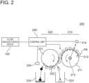
- Fig. 2 is a configuration diagram showing the filter inspection device according to an embodiment of the present invention.
- the filter inspection device 200 includes an inspection section 210, a removal section 220, a camera (image capturing unit) 230, and the control unit (analysis unit, notification unit) 240.
- the inspection section 210 includes an inspection drum (conveying unit) 211, suction grooves 212, a light emitter 213, and a light receiver 214. After the filter rod continuum RS conveyed in a length direction is cut into separate filter rods FR at the filter manufacturing device 100, the filter rods FR are transferred to the inspection drum 211 by a pickup mechanism not shown.
- the inspection drum 211 sucks the filter rods FR by the suction grooves 212 that are arranged at intervals on an outer periphery of the inspection drum 211, and rotates counterclockwise. A conveying direction of the filter rods FR is thereby converted from the length direction to a circumferential direction.
- the light emitter 213 is disposed at a center of the inspection drum 211, for example, and radiates detection light on the filter rod FR that is sucked by the suction groove 212.
- the light receiver 214 is disposed on an extension line connecting the light emitter 213 and the filter rod FR that is irradiated with the inspection light, and receives the detection light that is transmitted through the filter rod FR.
- the control unit 240 performs defect inspection on the filter rod FR by inspecting a segment length of the filter rod FR, presence/absence of damage, and the like based on an amount of detection light received by the light receiver 214. In the case where the filter rod FR is determined to be defective, the control unit 240 controls the removal section 220 to remove the filter rod FR.
- the light emitter 213 and the light receiver 214 may be replaced with a reflective light sensor.
- the control unit 240 may perform defect inspection on the filter rod FR by detecting a reflection amount of light reflected by the filter rod FR.
- the removal section 220 includes a removal drum (conveying unit) 221, suction grooves (removing units) 222, a first container 223, and a second container 224.
- the filter rod FR conveyed by the inspection drum 211 is transferred to the removal drum 221 at a part where the inspection drum 211 and the removal drum 221 face each other.
- the removal drum 221 sucks the filter rods FR by the suction grooves 222 that are arranged at intervals on an outer periphery of the removal drum 221, and rotates clockwise.
- a seam inspection device for a tobacco filter according to the present invention includes the control unit 240, the camera 230, and the second container 224.
- the first container 223 and the second container 224 are disposed below the removal drum 221.
- the control unit 240 stops suction by the suction groove 222 at a time when the filter rod FR is conveyed to above the first container 223, and removes the filter rod FR into the first container 223.
- the control unit 240 stops suction by the suction groove 222 when a filter rod FR in a predetermined range including the seam of the paper webs WP is conveyed to above the second container 224, and removes a bundle of filter rods FR into the second container 224.
- the camera 230 is disposed above the second container 224, and captures an image of the bundle of filter rods FR removed into the second container 224.
- a pattern of the seam of the paper webs WP that is captured by the camera 230 patterns as shown in Figs. 3 and 4 are conceivable.
- Fig. 3 shows a pattern where a seal at the seam is at a middle portion of a filter rod FR, or in other words, a pattern where the filter rods FR are cut at a part other than the seam of the paper webs WP.
- Fig. 4 shows a pattern where the seal at the seam is at end portions of filter rods FR, or in other words, a pattern where the filter rods FR are cut at a seam part of the paper webs WP.
- the control unit 240 analyzes image data of the filter rods FR captured by the camera 230, and detects the seam of the paper webs WP. More specifically, the control unit 240 performs edge detection on the image data of the filter rods FR, and determines whether there are edges on both sides of the seal at the seam. Additionally, the control unit 240 may perform negative-positive reversal on the image data at the time of edge detection.
- the control unit 240 determines that the filter rods FR are cut at a part other than the seam part of the paper webs WP, and when the edge is present only on one side of the seal at the seam, the control unit 240 determines that the filter rods FR are cut at the seam part of the paper webs WP.
- the control unit 240 measures a length of the seal at the seam, and if the length is equal to or greater than a predetermined threshold, the control unit 240 determines that the filter rod FR including the seam of the paper webs WP is appropriately removed. Furthermore, in the case where the edge is present only on one side of the seal at the seam, the control unit 240 detects the number of seals at the seam, and if there are two or more, the control unit 240 determines that the filter rods FR including the seam of the paper webs WP are appropriately removed.
- control unit 240 determines that the filter rod FR including the seam of the paper webs WP is not appropriately removed. In the case of determining that the filter rod FR including the seam of the paper webs WP is not appropriately removed, the control unit 240 outputs the stop signal for the filter manufacturing device 100 to the control unit 50 of the filter manufacturing device 100.
- the suction grooves 222 remove a bundle of filter rods FR in a predetermined range including the seam of the paper webs WP from the removal drum 221 based on the seam detection signal input from the filter manufacturing device 100, the camera 230 captures an image of the removed filter rods FR, and the control unit 240 analyzes the image data of the captured filter rods FR, and the seam of the paper webs WP is thus detected. Accordingly, by detecting whether the removed filter rod FR includes the seam of the paper webs WP, whether the filter rod FR including the seam is appropriately removed may be inspected.
- control unit 240 outputs the stop signal to the filter manufacturing device 100, and the filter manufacturing device 100 may thus be stopped, and the filter rod FR including the seam of the paper webs WP may be prevented from flowing to processes at a later stage.
- control unit 240 performs edge detection, the seam of the paper webs WP may be detected with high accuracy.
- structures for inspecting the filter rod FR received from the filter manufacturing device 100 may be used also for detection of the seam of the paper webs WP, and thus, structures necessary for detecting the seam of the paper webs WP may be reduced, and the configuration of the seam inspection device for a tobacco filter may be simplified.
Landscapes
- Health & Medical Sciences (AREA)
- General Health & Medical Sciences (AREA)
- Toxicology (AREA)
- Cigarettes, Filters, And Manufacturing Of Filters (AREA)
Abstract
Description
- The present invention relates to a seam inspection device and a seam inspection method for a tobacco filter.
- A tobacco filter (a filter rod) formed by a filter manufacturing device includes a rod member formed by a filter material, and a paper web (rolling paper) enveloping the rod member. More specifically, the filter rod is formed by forming a filter rod continuum by wrapping the paper web around the rod member and gluing an overlapped part of the paper web, and then, cutting the filter rod continuum into a predetermined length.
- The paper web here has a finite length. A plurality (such as two) of paper webs having a finite length are installed on the filter manufacturing device in a state of being wound around bobbins, and a terminal end of the paper web on one bobbin and a start end of the paper web on the other bobbin are spliced with a seal or the like by a rolling paper supply unit such that the paper web is continuously supplied. By successively replacing an empty bobbin with a new bobbin, the filter rod may be continuously manufactured.
- A filter inspection device performs defect inspection on the filter rod that is cut into a predetermined length. More specifically, inspection is performed with respect to a segment length of the filter rod, presence/absence of damage, and the like, and a filter rod that is determined to be defective is removed by a removing unit.
- Additionally, when a seam of the paper webs is formed on the filter rod, the filter rod is treated as a defective item due to having a different rolling paper thickness or color compared to a non-defective item. Accordingly, a filter rod including a seam of the paper webs is desirably appropriately removed by the removing unit so that the filter rod including the seam does not flow to processes at a later stage.
- A conventional filter inspection device removes a filter rod by a removing unit with seam detection at a rolling paper supply unit as a trigger. More specifically, a sensor for detecting a seam of paper webs is provided near the rolling paper supply unit, and the sensor outputs a seam detection signal when detecting a seam of paper webs that are supplied by the rolling paper supply unit. The removing unit removes a bundle of filter rods in a predetermined range including the seam of the paper webs according to the seam detection signal, at a timing when the filter rods pass the removing unit.
- At this time, the filter rod including the seam of the paper webs is possibly not appropriately removed due to erroneous operation of the removing unit or the like. Moreover, the removing unit does not include a function of stopping the filter manufacturing device. Accordingly, an operator has to visually check whether the removed filter rod includes the seam of the paper webs, and the operator has to stop the filter manufacturing device as necessary.
- Furthermore, a knife mechanism of the filter manufacturing device for cutting a filter rod continuum into a predetermined length is not synchronized with the seam detection signal. Accordingly, for example, when a filter rod continuum is cut at the seam of the paper webs, if the length of the seam is 19 mm, a filter rod including 18 mm of seam and a filter rod including 1 mm of seam are possibly cut. In such a case, it is difficult for the operator to check whether the filter rod including 1 mm of seam is removed or not.
- Moreover, these days, a paper web having a greater thickness than a conventional item is sometimes used by the filter manufacturing device, and in such a case, exchange of the bobbin is reduced to once every three minutes from a conventional case of once every 15 minutes, for example. Accordingly, it is even more difficult for the operator to check whether a filter rod including the seam of the paper webs is removed or not.
- In other words, simply removing a filter rod with seam detection at the rolling paper supply unit as the trigger does not mean that a filter rod including the seam is appropriately removed, and a filter rod including the seam possibly flows to processes at a later stage.
- In relation to inspection of the filter rod, there is known an inspection system for determining, during a manufacturing process of the filter rod, whether a filter rod continuum is cut at a desired position or not, and for adjusting a position of a cutting device in a case where it is determined that cutting is performed too early or too late (for example, see PTL 1).
- PTL 1:
Japanese Translation of PCT International Application Publication No. 2003-505061 - However, the inspection system of PTL 1 is for determining, in the manufacturing process of the filter rod, whether a filter rod continuum is cut at a desired position or not, and is not capable of detecting whether a removed filter rod includes a seam of paper webs or not. Moreover, in the case where the position of the cutting device is adjusted, a length of filter rods that are formed may be varied, thereby affecting processes at a later stage.
- The present invention has been made to at least partially solve the problems as described above, and is aimed at achieving a seam inspection device and a seam inspection method for a tobacco filter, with which whether a filter rod including a seam of paper webs is appropriately removed or not can be inspected by detecting whether a removed filter rod includes the seam or not.
- In a first mode of the present invention, there is provided a seam inspection device for a tobacco filter. The seam inspection device for a tobacco filter is applied to a filter inspection device for inspecting a filter rod manufactured by a filter manufacturing device, where the filter manufacturing device is for forming filter rods by cutting, into a predetermined length, a filter rod continuum that is formed by wrapping a paper web around a rod member formed by a filter material, where the filter manufacturing device continuously supplies the paper web through successive splicing, the filter inspection device removes a bundle of the filter rods in a predetermined range including a seam of the paper webs by a removing unit based on a seam detection signal input from the filter manufacturing device, from a conveying unit for conveying the filter rod received from the filter manufacturing device, and the seam inspection device includes a container for housing the filter rod that is removed from the conveying unit, an image capturing unit for capturing an image of the filter rod housed in the container, and an analysis unit for analyzing image data of the filter rod captured by the image capturing unit, and detecting the seam of the paper webs.
- According to the first mode of the present invention, the filter rod removed from the conveying unit by the removing unit is housed in the container, the image capturing unit captures an image of the filter rod housed in the container, and the analysis unit analyzes the image data of the captured filter rod, and the seam of the paper webs is thereby detected. Accordingly, whether a filter rod including the seam of the paper webs is appropriately removed may be inspected by detecting whether a removed filter rod includes the seam.
- A second mode of the present invention according to the first mode further includes a notification unit for outputting a stop signal to the filter manufacturing device in a case where the seam of the paper webs is not detected by the analysis unit.
- According to the second mode of the present invention, in a case where the seam of the paper webs is not detected by the analysis unit, the notification unit outputs the stop signal to the filter manufacturing device, and the filter manufacturing device may thus be stopped and a filter rod including the seam of the paper webs may be prevented from flowing to processes at a later stage.
- In a third mode of the present invention according to the first or second mode, the analysis unit detects the seam of the paper webs by performing edge detection on the image data of the filter rod.
- According to the third mode of the present invention, because the analysis unit performs edge detection, the seam of the paper webs may be detected with higher accuracy.
- In a fourth mode of the present invention according to any one of the first to third modes, the conveying unit is a drum used for inspection of the filter rod received from the filter manufacturing device, and the removing unit sucks and holds the filter rod at an outer periphery of the drum.
- According to the fourth mode of the present invention, structures for inspecting the filter rod received from the filter manufacturing device may be used for detection of the seam of the paper webs, and thus, structures necessary for detecting the seam of the paper webs may be reduced, and the configuration of the seam inspection device for a tobacco filter may be simplified.
- In a fifth mode of the present invention, there is provided a seam inspection method for a tobacco filter. The seam inspection method for a tobacco filter is a seam inspection method for a tobacco filter that is applied to a filter inspection device for inspecting a filter rod manufactured by a filter manufacturing device, where the filter manufacturing device is for forming filter rods by cutting, into a predetermined length, a filter rod continuum that is formed by wrapping a paper web around a rod member formed by a filter material, where the filter manufacturing device continuously supplies the paper web through successive splicing, the filter inspection device removes a bundle of the filter rods in a predetermined range including a seam of the paper webs by a removing unit based on a seam detection signal input from the filter manufacturing device, from a conveying unit for conveying the filter rod received from the filter manufacturing device, and the seam inspection method includes a housing step for housing, in a container, the filter rod that is removed from the conveying unit, an image capturing step for capturing, by an image capturing unit, an image of the filter rod housed in the housing step, and an analysis step for analyzing, by an analysis unit, image data of the filter rod captured in the image capturing step, and detecting the seam of the paper webs.
- According to the fifth mode of the present invention, a filter rod removed from the conveying unit by the removing unit is housed in the container in the housing step, the filter rod housed in the container is captured in the image capturing step, and the image data of the captured filter rod is analyzed in the analysis step, and the seam of the paper webs is thereby detected. Accordingly, whether a filter rod including the seam of the paper webs is appropriately removed may be inspected by detecting whether a removed filter rod includes the seam.
- A sixth mode of the present invention according to the fifth mode further includes a notification step for outputting a stop signal to the filter manufacturing device in a case where the seam of the paper webs is not detected in the analysis step.
- According to the sixth mode of the present invention, in a case where the seam of the paper webs is not detected in the analysis step, the stop signal is output to the filter manufacturing device in the notification step, and the filter manufacturing device may thus be stopped and a filter rod including the seam of the paper webs may be prevented from flowing to processes at a later stage.
-
- [
Fig. 1] Fig. 1 is a configuration diagram showing a filter manufacturing device according to an embodiment of the present invention. - [
Fig. 2] Fig. 2 is a configuration diagram showing a filter inspection device according to an embodiment of the present invention. - [
Fig. 3] Fig. 3 is a schematic diagram showing filter rods in a second container shown inFig. 2 . - [
Fig. 4] Fig. 4 is a schematic diagram showing filter rods in the second container shown inFig. 2 . - Hereinafter, an embodiment of the present invention will be described with reference to the drawings. In the drawings described below, the same or corresponding structural elements are denoted with the same reference sign, and redundant description is omitted.
- First, a filter manufacturing device for manufacturing a filter rod will be described with reference to
Fig. 1. Fig. 1 is a configuration diagram showing a filter manufacturing device according to an embodiment of the present invention. As shown inFig. 1 , afilter manufacturing device 100 roughly includes atow processing section 10, a formingsection 20, awrapping section 30, acutting section 40, and acontrol unit 50. - For example, the
tow processing section 10 includes abale 11 containing a filter material of cellulose acetate fiber, or in other words, a tow T, and atow path 12 extends from thebale 11. Thetow path 12 includes aprimary banding jet 13, aguide roller 14, a pair ofpre-tensioning rollers 15, a pair ofblooming rollers 16, and asecondary banding jet 17 that are sequentially disposed from thebale 11 side, and thesecondary banding jet 17 is positioned at a terminal end of thetow path 12. - When the tow T passes through the
primary banding jet 13, theprimary banding jet 13 ejects compressed air from thebale 11 side toward the tow T. The ejected compressed air opens, or in other words, loosens, the tow T, and moderately stretches crimp of the tow T. - When the tow T reaches the
guide roller 14, theguide roller 14 directs a supply direction of the tow T to the pair ofpre-tensioning rollers 15, and the tow T passes between the pair ofpre-tensioning rollers 15. At this time, the pair ofpre-tensioning rollers 15 presses the opened tow T, applies a predetermined tensile force to the tow T in cooperation with the pair ofblooming rollers 16, and further stretches the crimp of the tow T. - Then, when the tow T passes between the pair of blooming
rollers 16, the pair of bloomingrollers 16 divides the opened tow T into a plurality of bundles, and supplies the bundles to thesecondary banding jet 17. - When the divided bundle of tow T passes through the
secondary banding jet 17, thesecondary banding jet 17 ejects compressed air toward the divided bundle, and the compressed air opens the divided bundle. As a result, the divided bundle spreads in a width direction of thetow path 12, and forms a flat filter web WF. Then, the filter web WF is fed to the formingsection 20. - The filter web WF fed to the forming
section 20 is conveyed toward atrumpet guide 21, and passes through thetrumpet guide 21. At this time, the filter web WF is squeezed into a rod shape by thetrumpet guide 21, and is formed into a rod member WR. That is, a width of the flat filter web WF is gradually reduced as the filter web WF is conveyed toward thetrumpet guide 21. Then, the rod member WR is fed to thewrapping section 30. - The
wrapping section 30 includes anendless garniture tape 31, and thegarniture tape 31 travels on a horizontal forming bed, not shown, in a conveying direction of the rod member WR. At an inlet position of thewrapping section 30, a paper web WP is supplied onto thegarniture tape 31 by a rollingpaper supply unit 32. - The rolling
paper supply unit 32 includes a plurality (such as two) ofbobbins 33 on which the paper web WP with a finite length is wound, and the paper web WP is supplied from thebobbin 33. Furthermore, when a terminal end of the paper web WP wound around onebobbin 33 is neared, the rollingpaper supply unit 32 splices the terminal end of the paper web WP on the onebobbin 33 to a start end of the paper web WP on theother bobbin 33 with a seal or the like. Anempty bobbin 33 is replaced by an operator. Anempty bobbin 33 is sequentially replaced with anew bobbin 33, and the rollingpaper supply unit 32 thus continuously supplies the paper web WP. - A
sensor 34 for detecting a seam of the paper webs WP is provided near the rollingpaper supply unit 32. Thesensor 34 detects the seal splicing the terminal end of the paper web WP on onebobbin 33 and the start end of the paper web WP on theother bobbin 33. When thesensor 34 detects the seam of the paper webs WP supplied from the rollingpaper supply unit 32, thecontrol unit 50 outputs a seam detection signal to acontrol unit 240 of afilter inspection device 200 described later. Additionally, thesensor 34 may instead be provided at thefilter inspection device 200. - The paper web WP supplied from the rolling
paper supply unit 32 is guided to thegarniture tape 31 via aspray gun 35. Thespray gun 35 applies an adhesive called rail glue to a center of the paper web WP in a width direction. - The rod member WR supplied from the
trumpet guide 21 is laid on the paper web WP at the inlet position. At this time, the rod member WR and the paper web WP are stuck together by the rail glue. - Then, the rod member WR and the paper web WP travel on the forming bed with the
garniture tape 31, and sequentially pass through atongue 36, a wrapping former 37, aheater 38, and a cooler 39. - The
tongue 36 operates in conjunction with the forming bed, and further compresses the rod member WR through thegarniture tape 31 and the paper web WP. At this time, a cross-section of the rod member WR is formed into a round shape, and the paper web WP and thegarniture tape 31 are bent into a U-shape in cross-section. At this time, a lower half of the rod member WR is covered with the paper web WP. - Then, when the rod member WR passes through the wrapping former 37, one side edge portion of the paper web WP is laid on one side of an upper half of the rod member WR through the
garniture tape 31, and at the same time, a spray gun, not shown, of the wrapping former 37 applies seam glue on the other side edge portion of the paper web WP. - Then, the other side edge portion of the paper web WP is laid on the rod member WR in the same manner through the
garniture tape 31, and is caused to overlap the one side edge portion of the paper web WP via the seam glue. At this time, both side edge portions of the paper web WP are stuck together by the seam glue, and the rod member WR is completely wrapped in the paper web WP, and a filter rod continuum RS is formed. - Then, the seam glue is dried when the filter rod continuum RS formed by the wrapping former 37 passes through the
heater 38, and the seam glue is cooled when the filter rod continuum RS passes through the cooler 39. - The cutting
section 40 includes arotary knife 41, and therotary knife 41 cuts the filter rod continuum RS conveyed from thewrapping section 30 into a predetermined length, and forms separate filter rods FR. - The
control unit 50 controls operation of thefilter manufacturing device 100. More specifically, thecontrol unit 50 controls operation of each drive part of thefilter manufacturing device 100, and stops driving of thefilter manufacturing device 100 when there is occurrence of abnormality. Moreover, thecontrol unit 50 is connected to thefilter inspection device 200. Thecontrol unit 50 outputs the seam detection signal from thesensor 34 to thecontrol unit 240 of thefilter inspection device 200, and stops driving of thefilter manufacturing device 100 when a stop signal is input from thecontrol unit 240. -
Fig. 2 is a configuration diagram showing the filter inspection device according to an embodiment of the present invention. As shown inFig. 2 , thefilter inspection device 200 includes aninspection section 210, aremoval section 220, a camera (image capturing unit) 230, and the control unit (analysis unit, notification unit) 240. - The
inspection section 210 includes an inspection drum (conveying unit) 211,suction grooves 212, alight emitter 213, and alight receiver 214. After the filter rod continuum RS conveyed in a length direction is cut into separate filter rods FR at thefilter manufacturing device 100, the filter rods FR are transferred to theinspection drum 211 by a pickup mechanism not shown. - The
inspection drum 211 sucks the filter rods FR by thesuction grooves 212 that are arranged at intervals on an outer periphery of theinspection drum 211, and rotates counterclockwise. A conveying direction of the filter rods FR is thereby converted from the length direction to a circumferential direction. - The
light emitter 213 is disposed at a center of theinspection drum 211, for example, and radiates detection light on the filter rod FR that is sucked by thesuction groove 212. Thelight receiver 214 is disposed on an extension line connecting thelight emitter 213 and the filter rod FR that is irradiated with the inspection light, and receives the detection light that is transmitted through the filter rod FR. - The
control unit 240 performs defect inspection on the filter rod FR by inspecting a segment length of the filter rod FR, presence/absence of damage, and the like based on an amount of detection light received by thelight receiver 214. In the case where the filter rod FR is determined to be defective, thecontrol unit 240 controls theremoval section 220 to remove the filter rod FR. - The
light emitter 213 and thelight receiver 214 may be replaced with a reflective light sensor. In the case where a reflective light sensor is used, thecontrol unit 240 may perform defect inspection on the filter rod FR by detecting a reflection amount of light reflected by the filter rod FR. - The
removal section 220 includes a removal drum (conveying unit) 221, suction grooves (removing units) 222, afirst container 223, and asecond container 224. The filter rod FR conveyed by theinspection drum 211 is transferred to theremoval drum 221 at a part where theinspection drum 211 and theremoval drum 221 face each other. Theremoval drum 221 sucks the filter rods FR by thesuction grooves 222 that are arranged at intervals on an outer periphery of theremoval drum 221, and rotates clockwise. Additionally, a seam inspection device for a tobacco filter according to the present invention includes thecontrol unit 240, thecamera 230, and thesecond container 224. - The
first container 223 and thesecond container 224 are disposed below theremoval drum 221. In the case where a filter rod FR that is defective is detected by theinspection section 210, thecontrol unit 240 stops suction by thesuction groove 222 at a time when the filter rod FR is conveyed to above thefirst container 223, and removes the filter rod FR into thefirst container 223. - Furthermore, when the seam detection signal is input from the
control unit 50 of thefilter manufacturing device 100, thecontrol unit 240 stops suction by thesuction groove 222 when a filter rod FR in a predetermined range including the seam of the paper webs WP is conveyed to above thesecond container 224, and removes a bundle of filter rods FR into thesecond container 224. - The
camera 230 is disposed above thesecond container 224, and captures an image of the bundle of filter rods FR removed into thesecond container 224. As a pattern of the seam of the paper webs WP that is captured by thecamera 230, patterns as shown inFigs. 3 and 4 are conceivable.Fig. 3 shows a pattern where a seal at the seam is at a middle portion of a filter rod FR, or in other words, a pattern where the filter rods FR are cut at a part other than the seam of the paper webs WP.Fig. 4 shows a pattern where the seal at the seam is at end portions of filter rods FR, or in other words, a pattern where the filter rods FR are cut at a seam part of the paper webs WP. - The
control unit 240 analyzes image data of the filter rods FR captured by thecamera 230, and detects the seam of the paper webs WP. More specifically, thecontrol unit 240 performs edge detection on the image data of the filter rods FR, and determines whether there are edges on both sides of the seal at the seam. Additionally, thecontrol unit 240 may perform negative-positive reversal on the image data at the time of edge detection. - At this time, if the edges are present on both sides of the seal at the seam, the
control unit 240 determines that the filter rods FR are cut at a part other than the seam part of the paper webs WP, and when the edge is present only on one side of the seal at the seam, thecontrol unit 240 determines that the filter rods FR are cut at the seam part of the paper webs WP. - Next, in the case where the edges are present on both sides of the seal at the seam, the
control unit 240 measures a length of the seal at the seam, and if the length is equal to or greater than a predetermined threshold, thecontrol unit 240 determines that the filter rod FR including the seam of the paper webs WP is appropriately removed. Furthermore, in the case where the edge is present only on one side of the seal at the seam, thecontrol unit 240 detects the number of seals at the seam, and if there are two or more, thecontrol unit 240 determines that the filter rods FR including the seam of the paper webs WP are appropriately removed. - In other cases, the
control unit 240 determines that the filter rod FR including the seam of the paper webs WP is not appropriately removed. In the case of determining that the filter rod FR including the seam of the paper webs WP is not appropriately removed, thecontrol unit 240 outputs the stop signal for thefilter manufacturing device 100 to thecontrol unit 50 of thefilter manufacturing device 100. - As described above, the
suction grooves 222 remove a bundle of filter rods FR in a predetermined range including the seam of the paper webs WP from theremoval drum 221 based on the seam detection signal input from thefilter manufacturing device 100, thecamera 230 captures an image of the removed filter rods FR, and thecontrol unit 240 analyzes the image data of the captured filter rods FR, and the seam of the paper webs WP is thus detected. Accordingly, by detecting whether the removed filter rod FR includes the seam of the paper webs WP, whether the filter rod FR including the seam is appropriately removed may be inspected. - Furthermore, in the case where the seam of the paper webs WP is not detected by the
control unit 240, thecontrol unit 240 outputs the stop signal to thefilter manufacturing device 100, and thefilter manufacturing device 100 may thus be stopped, and the filter rod FR including the seam of the paper webs WP may be prevented from flowing to processes at a later stage. - Moreover, because the
control unit 240 performs edge detection, the seam of the paper webs WP may be detected with high accuracy. - Moreover, structures for inspecting the filter rod FR received from the
filter manufacturing device 100 may be used also for detection of the seam of the paper webs WP, and thus, structures necessary for detecting the seam of the paper webs WP may be reduced, and the configuration of the seam inspection device for a tobacco filter may be simplified. - Heretofore, embodiments of the present invention have been described, but the embodiments of the invention described above are for facilitating understanding of the present invention, and are not intended to limit the present invention. The present invention may be modified or improved without departing from the gist of the present invention, and the present invention includes equivalents thereof. Furthermore, any combination or omission of structural elements described in the scope of the claims and the specification is possible within a scope where at least a part of the above-mentioned problem can be solved or a scope where at least a part of the effect can be achieved.
-
- WP
- paper web
- FR
- filter rod
- 200
- filter inspection device
- 210
- inspection section
- 211
- inspection drum
- 212
- suction groove
- 213
- light emitter
- 214
- light receiver
- 220
- removal section
- 221
- removal drum
- 222
- suction groove
- 223
- first container
- 224
- second container
- 230
- camera
- 240
- control unit
Claims (6)
- A seam inspection device for a tobacco filter that is applied to a filter inspection device for inspecting a filter rod manufactured by a filter manufacturing device, whereinthe filter manufacturing device is for forming filter rods by cutting, into a predetermined length, a filter rod continuum that is formed by wrapping a paper web around a rod member formed by a filter material, where the filter manufacturing device continuously supplies the paper web through successive splicing,the filter inspection device removes a bundle of the filter rods in a predetermined range including a seam of the paper webs by a removing unit based on a seam detection signal input from the filter manufacturing device, from a conveying unit for conveying the filter rod received from the filter manufacturing device, andthe seam inspection device includesa container for housing the filter rod that is removed from the conveying unit,an image capturing unit for capturing an image of the filter rod housed in the container, andan analysis unit for analyzing image data of the filter rod captured by the image capturing unit, and detecting the seam of the paper webs.
- The seam inspection device for a tobacco filter according to claim 1, further comprising a notification unit for outputting a stop signal to the filter manufacturing device in a case where the seam of the paper webs is not detected by the analysis unit.
- The seam inspection device for a tobacco filter according to claim 1 or 2, wherein the analysis unit detects the seam of the paper webs by performing edge detection on the image data of the filter rod.
- The seam inspection device for a tobacco filter according to any one of claims 1 to 3, whereinthe conveying unit is a drum used for inspection of the filter rod received from the filter manufacturing device, andthe removing unit sucks and holds the filter rod at an outer periphery of the drum.
- A seam inspection method for a tobacco filter that is applied to a filter inspection device for inspecting a filter rod manufactured by a filter manufacturing device, whereinthe filter manufacturing device is for forming filter rods by cutting, into a predetermined length, a filter rod continuum that is formed by wrapping a paper web around a rod member formed by a filter material, where the filter manufacturing device continuously supplies the paper web through successive splicing,the filter inspection device removes a bundle of the filter rods in a predetermined range including a seam of the paper webs by a removing unit based on a seam detection signal input from the filter manufacturing device, from a conveying unit for conveying the filter rod received from the filter manufacturing device, andthe seam inspection method comprisesa housing step for housing, in a container, the filter rod that is removed from the conveying unit,an image capturing step for capturing, by an image capturing unit, an image of the filter rod housed in the housing step, andan analysis step for analyzing, by an analysis unit, image data of the filter rod captured in the image capturing step, and detecting the seam of the paper webs.
- The seam inspection method for a tobacco filter according to claim 5, further comprising a notification step for outputting a stop signal to the filter manufacturing device in a case where the seam of the paper webs is not detected in the analysis step.
Applications Claiming Priority (1)
| Application Number | Priority Date | Filing Date | Title |
|---|---|---|---|
| PCT/JP2021/043787 WO2023100222A1 (en) | 2021-11-30 | 2021-11-30 | Seam inspection device and seam inspection method for cigarette filter |
Publications (2)
| Publication Number | Publication Date |
|---|---|
| EP4442131A1 true EP4442131A1 (en) | 2024-10-09 |
| EP4442131A4 EP4442131A4 (en) | 2025-09-10 |
Family
ID=86611734
Family Applications (1)
| Application Number | Title | Priority Date | Filing Date |
|---|---|---|---|
| EP21966308.5A Pending EP4442131A4 (en) | 2021-11-30 | 2021-11-30 | Seam inspection device and seam inspection method for cigarette filters |
Country Status (2)
| Country | Link |
|---|---|
| EP (1) | EP4442131A4 (en) |
| WO (1) | WO2023100222A1 (en) |
Family Cites Families (7)
| Publication number | Priority date | Publication date | Assignee | Title |
|---|---|---|---|---|
| US4059120A (en) * | 1974-02-05 | 1977-11-22 | Molins Limited | Manufacture of cigarettes |
| GB2102273B (en) * | 1981-07-15 | 1985-08-07 | Hauni Werke Koerber & Co Kg | Method and machine for making filter rod sections for cigarettes or the like |
| US6264591B1 (en) | 1999-07-27 | 2001-07-24 | Philip Morris Incorporated | Plug combiner inspection system and method |
| DE102009016500B4 (en) * | 2009-04-08 | 2024-02-08 | Körber Technologies Gmbh | Method for operating a filter rod machine and filter rod machine |
| CN106723325A (en) * | 2015-11-25 | 2017-05-31 | 由国峰 | A kind of filter maker paper joint rejects detection means |
| EP3760057B2 (en) * | 2019-07-05 | 2025-10-22 | International Tobacco Machinery Poland SP. Z O.O. | The method and device for checking the quality of rod-like products |
| CN211832797U (en) * | 2019-11-22 | 2020-11-03 | 红云红河烟草(集团)有限责任公司 | Filter rod forming unit joint removing monitoring device |
-
2021
- 2021-11-30 WO PCT/JP2021/043787 patent/WO2023100222A1/en not_active Ceased
- 2021-11-30 EP EP21966308.5A patent/EP4442131A4/en active Pending
Also Published As
| Publication number | Publication date |
|---|---|
| WO2023100222A1 (en) | 2023-06-08 |
| EP4442131A4 (en) | 2025-09-10 |
Similar Documents
| Publication | Publication Date | Title |
|---|---|---|
| USRE48182E1 (en) | Apparatus and method for minimizing waste and improving quality and production in web processing operations by automatic cuff defect correction | |
| EP2036522B1 (en) | Apparatus and method for minimizing waste and improving quality and production in web processing operations | |
| US9387131B2 (en) | Apparatus and method for minimizing waste and improving quality and production in web processing operations by automated threading and re-threading of web materials | |
| US8577122B2 (en) | Method and device for testing cigarette packages wrapped with film | |
| JP5647810B2 (en) | Operation method of continuous filter manufacturing machine and continuous filter manufacturing machine | |
| JPWO2011064857A1 (en) | Cigarette inspection device | |
| CN101061890B (en) | Method and device for monitoring the position of wrapping paper tape, tobacco processing machine and application | |
| US11981520B2 (en) | Apparatus and method for web twist defect correction | |
| WO2023100222A1 (en) | Seam inspection device and seam inspection method for cigarette filter | |
| CN220694381U (en) | Cigarette tipping arrangement and cigarette tipping system | |
| CN211721868U (en) | Cigarette rolling and connecting equipment | |
| EP4275521A1 (en) | Tobacco filter inspection apparatus | |
| JP7136007B2 (en) | Sheet conveyance failure detection device and conveyance failure detection method | |
| CN111336925A (en) | Inspection method of composite cord fabric material | |
| CN222607245U (en) | Cigarette package abnormality detection device and cigarette packaging system | |
| CN116941817A (en) | Cigarette connecting equipment and cigarette connecting system | |
| EP4410126A1 (en) | Method for determining the conformity of a type of filter being processed in a machine of the tobacco industry | |
| JP2016144903A (en) | Saddle stitch book wire configuration examination apparatus and saddle stitch machine | |
| JPS629302B2 (en) | ||
| CN119000600A (en) | Raw smoke detection device and method | |
| JPH04137366U (en) | Negative film abnormality detection processing device | |
| JPH09300291A (en) | Paper sheet cutting apparatus, paper sheet processing apparatus, and paper sheet cutting method |
Legal Events
| Date | Code | Title | Description |
|---|---|---|---|
| STAA | Information on the status of an ep patent application or granted ep patent |
Free format text: STATUS: THE INTERNATIONAL PUBLICATION HAS BEEN MADE |
|
| PUAI | Public reference made under article 153(3) epc to a published international application that has entered the european phase |
Free format text: ORIGINAL CODE: 0009012 |
|
| STAA | Information on the status of an ep patent application or granted ep patent |
Free format text: STATUS: REQUEST FOR EXAMINATION WAS MADE |
|
| 17P | Request for examination filed |
Effective date: 20240513 |
|
| AK | Designated contracting states |
Kind code of ref document: A1 Designated state(s): AL AT BE BG CH CY CZ DE DK EE ES FI FR GB GR HR HU IE IS IT LI LT LU LV MC MK MT NL NO PL PT RO RS SE SI SK SM TR |
|
| DAV | Request for validation of the european patent (deleted) | ||
| DAX | Request for extension of the european patent (deleted) | ||
| A4 | Supplementary search report drawn up and despatched |
Effective date: 20250808 |
|
| RIC1 | Information provided on ipc code assigned before grant |
Ipc: A24D 3/02 20060101AFI20250804BHEP Ipc: A24C 5/34 20060101ALI20250804BHEP Ipc: G01N 21/952 20060101ALN20250804BHEP |
|
| RIC1 | Information provided on ipc code assigned before grant |
Ipc: A24D 3/02 20060101AFI20260121BHEP Ipc: A24C 5/34 20060101ALI20260121BHEP Ipc: G01N 21/952 20060101ALN20260121BHEP |
|
| STAA | Information on the status of an ep patent application or granted ep patent |
Free format text: STATUS: EXAMINATION IS IN PROGRESS |
|
| RIC1 | Information provided on ipc code assigned before grant |
Ipc: A24D 3/02 20060101AFI20260224BHEP Ipc: A24C 5/34 20060101ALI20260224BHEP Ipc: G01N 21/952 20060101ALN20260224BHEP |
|
| 17Q | First examination report despatched |
Effective date: 20260327 |