EP4440938B1 - Verfahren und vorrichtung zum schneiden einer packungswand - Google Patents
Verfahren und vorrichtung zum schneiden einer packungswand Download PDFInfo
- Publication number
- EP4440938B1 EP4440938B1 EP22829841.0A EP22829841A EP4440938B1 EP 4440938 B1 EP4440938 B1 EP 4440938B1 EP 22829841 A EP22829841 A EP 22829841A EP 4440938 B1 EP4440938 B1 EP 4440938B1
- Authority
- EP
- European Patent Office
- Prior art keywords
- pack
- cut
- cutting
- wall
- glue
- Prior art date
- Legal status (The legal status is an assumption and is not a legal conclusion. Google has not performed a legal analysis and makes no representation as to the accuracy of the status listed.)
- Active
Links
Images


Classifications
-
- B—PERFORMING OPERATIONS; TRANSPORTING
- B65—CONVEYING; PACKING; STORING; HANDLING THIN OR FILAMENTARY MATERIAL
- B65B—MACHINES, APPARATUS OR DEVICES FOR, OR METHODS OF, PACKAGING ARTICLES OR MATERIALS; UNPACKING
- B65B19/00—Packaging rod-shaped or tubular articles susceptible to damage by abrasion or pressure, e.g. cigarettes, cigars, macaroni, spaghetti, drinking straws or welding electrodes
- B65B19/02—Packaging cigarettes
- B65B19/22—Wrapping the cigarettes; Packaging the cigarettes in containers formed by folding wrapping material around formers
-
- B—PERFORMING OPERATIONS; TRANSPORTING
- B26—HAND CUTTING TOOLS; CUTTING; SEVERING
- B26D—CUTTING; DETAILS COMMON TO MACHINES FOR PERFORATING, PUNCHING, CUTTING-OUT, STAMPING-OUT OR SEVERING
- B26D7/00—Details of apparatus for cutting, cutting-out, stamping-out, punching, perforating, or severing by means other than cutting
- B26D7/18—Means for removing cut-out material or waste
- B26D7/1845—Means for removing cut-out material or waste by non mechanical means
- B26D7/1863—Means for removing cut-out material or waste by non mechanical means by suction
-
- B—PERFORMING OPERATIONS; TRANSPORTING
- B26—HAND CUTTING TOOLS; CUTTING; SEVERING
- B26D—CUTTING; DETAILS COMMON TO MACHINES FOR PERFORATING, PUNCHING, CUTTING-OUT, STAMPING-OUT OR SEVERING
- B26D7/00—Details of apparatus for cutting, cutting-out, stamping-out, punching, perforating, or severing by means other than cutting
- B26D7/27—Means for performing other operations combined with cutting
-
- B—PERFORMING OPERATIONS; TRANSPORTING
- B65—CONVEYING; PACKING; STORING; HANDLING THIN OR FILAMENTARY MATERIAL
- B65B—MACHINES, APPARATUS OR DEVICES FOR, OR METHODS OF, PACKAGING ARTICLES OR MATERIALS; UNPACKING
- B65B19/00—Packaging rod-shaped or tubular articles susceptible to damage by abrasion or pressure, e.g. cigarettes, cigars, macaroni, spaghetti, drinking straws or welding electrodes
- B65B19/02—Packaging cigarettes
- B65B19/12—Inserting the cigarettes, or wrapped groups thereof, into preformed containers
- B65B19/20—Inserting the cigarettes, or wrapped groups thereof, into preformed containers into boxes with hinged lids
-
- B—PERFORMING OPERATIONS; TRANSPORTING
- B65—CONVEYING; PACKING; STORING; HANDLING THIN OR FILAMENTARY MATERIAL
- B65B—MACHINES, APPARATUS OR DEVICES FOR, OR METHODS OF, PACKAGING ARTICLES OR MATERIALS; UNPACKING
- B65B61/00—Auxiliary devices, not otherwise provided for, for operating on sheets, blanks, webs, binding material, containers or packages
- B65B61/005—Auxiliary devices, not otherwise provided for, for operating on sheets, blanks, webs, binding material, containers or packages for removing material by cutting
-
- B—PERFORMING OPERATIONS; TRANSPORTING
- B65—CONVEYING; PACKING; STORING; HANDLING THIN OR FILAMENTARY MATERIAL
- B65B—MACHINES, APPARATUS OR DEVICES FOR, OR METHODS OF, PACKAGING ARTICLES OR MATERIALS; UNPACKING
- B65B61/00—Auxiliary devices, not otherwise provided for, for operating on sheets, blanks, webs, binding material, containers or packages
- B65B61/04—Auxiliary devices, not otherwise provided for, for operating on sheets, blanks, webs, binding material, containers or packages for severing webs, or for separating joined packages
- B65B61/06—Auxiliary devices, not otherwise provided for, for operating on sheets, blanks, webs, binding material, containers or packages for severing webs, or for separating joined packages by cutting
- B65B61/08—Auxiliary devices, not otherwise provided for, for operating on sheets, blanks, webs, binding material, containers or packages for severing webs, or for separating joined packages by cutting using rotary cutters
-
- B—PERFORMING OPERATIONS; TRANSPORTING
- B65—CONVEYING; PACKING; STORING; HANDLING THIN OR FILAMENTARY MATERIAL
- B65D—CONTAINERS FOR STORAGE OR TRANSPORT OF ARTICLES OR MATERIALS, e.g. BAGS, BARRELS, BOTTLES, BOXES, CANS, CARTONS, CRATES, DRUMS, JARS, TANKS, HOPPERS, FORWARDING CONTAINERS; ACCESSORIES, CLOSURES, OR FITTINGS THEREFOR; PACKAGING ELEMENTS; PACKAGES
- B65D85/00—Containers, packaging elements or packages, specially adapted for particular articles or materials
- B65D85/07—Containers, packaging elements or packages, specially adapted for particular articles or materials for compressible or flexible articles
- B65D85/08—Containers, packaging elements or packages, specially adapted for particular articles or materials for compressible or flexible articles rod-shaped or tubular
- B65D85/10—Containers, packaging elements or packages, specially adapted for particular articles or materials for compressible or flexible articles rod-shaped or tubular for cigarettes
- B65D85/1036—Containers formed by erecting a rigid or semi-rigid blank
- B65D85/1045—Containers formed by erecting a rigid or semi-rigid blank having a cap-like lid hinged to an edge
-
- B—PERFORMING OPERATIONS; TRANSPORTING
- B65—CONVEYING; PACKING; STORING; HANDLING THIN OR FILAMENTARY MATERIAL
- B65D—CONTAINERS FOR STORAGE OR TRANSPORT OF ARTICLES OR MATERIALS, e.g. BAGS, BARRELS, BOTTLES, BOXES, CANS, CARTONS, CRATES, DRUMS, JARS, TANKS, HOPPERS, FORWARDING CONTAINERS; ACCESSORIES, CLOSURES, OR FITTINGS THEREFOR; PACKAGING ELEMENTS; PACKAGES
- B65D85/00—Containers, packaging elements or packages, specially adapted for particular articles or materials
- B65D85/07—Containers, packaging elements or packages, specially adapted for particular articles or materials for compressible or flexible articles
- B65D85/08—Containers, packaging elements or packages, specially adapted for particular articles or materials for compressible or flexible articles rod-shaped or tubular
- B65D85/10—Containers, packaging elements or packages, specially adapted for particular articles or materials for compressible or flexible articles rod-shaped or tubular for cigarettes
- B65D85/1036—Containers formed by erecting a rigid or semi-rigid blank
- B65D85/1063—Containers formed by erecting a rigid or semi-rigid blank so as to form two cigarette-compartments interconnected by a hinge-portion
-
- B—PERFORMING OPERATIONS; TRANSPORTING
- B26—HAND CUTTING TOOLS; CUTTING; SEVERING
- B26D—CUTTING; DETAILS COMMON TO MACHINES FOR PERFORATING, PUNCHING, CUTTING-OUT, STAMPING-OUT OR SEVERING
- B26D1/00—Cutting through work characterised by the nature or movement of the cutting member or particular materials not otherwise provided for; Apparatus or machines therefor; Cutting members therefor
- B26D1/01—Cutting through work characterised by the nature or movement of the cutting member or particular materials not otherwise provided for; Apparatus or machines therefor; Cutting members therefor involving a cutting member which does not travel with the work
- B26D1/12—Cutting through work characterised by the nature or movement of the cutting member or particular materials not otherwise provided for; Apparatus or machines therefor; Cutting members therefor involving a cutting member which does not travel with the work having a cutting member moving about an axis
- B26D1/14—Cutting through work characterised by the nature or movement of the cutting member or particular materials not otherwise provided for; Apparatus or machines therefor; Cutting members therefor involving a cutting member which does not travel with the work having a cutting member moving about an axis with a circular cutting member, e.g. disc cutter
- B26D1/141—Cutting through work characterised by the nature or movement of the cutting member or particular materials not otherwise provided for; Apparatus or machines therefor; Cutting members therefor involving a cutting member which does not travel with the work having a cutting member moving about an axis with a circular cutting member, e.g. disc cutter for thin material, e.g. for sheets, strips or the like
-
- B—PERFORMING OPERATIONS; TRANSPORTING
- B26—HAND CUTTING TOOLS; CUTTING; SEVERING
- B26D—CUTTING; DETAILS COMMON TO MACHINES FOR PERFORATING, PUNCHING, CUTTING-OUT, STAMPING-OUT OR SEVERING
- B26D11/00—Combinations of several similar cutting apparatus
Definitions
- the present invention relates to a method and unit to cut a wall of a pack, in particular of smoking articles.
- the present invention finds advantageous application in a packing machine (for example a cellophane wrapping machine) for manufacturing a pack of cigarettes known as "book-pack, to which the following disclosure will make explicit reference without thereby losing generality.
- a "book-pack” pack of cigarettes comprises (at least) two containers, which house respective wrapped groups of cigarettes, have respective open upper ends, and are hinged to one another so as to rotate between a closed configuration, in which the two containers are overlapping one another, and an open configuration, in which the two containers are separate; furthermore, a lid is provided which is hinged to a rear container and, when in a closed position, embraces the upper part of both containers.
- a "book-pack" pack of cigarettes provides for the forming of the two containers by using two corresponding blanks which are folded around the respective wrapped groups of cigarettes, coupling (overlapping) the two containers, and then folding around the two coupled (overlapped) containers a third blank that joins the two containers and forms the common lid.
- a double cut is made (that is, two close and parallel cuts) to remove a flap (strap) from the bottom wall so as to obtain a clear separation between the two containers.
- a cutting unit is used that is provided with two parallel and adjacent rotary blades, which are partially housed in a collecting chamber subject to suction, which should capture and remove the strap as soon as the strap has been separated from the rest of the bottom wall.
- US7415812B2 describes a packing machine for manufacturing a pack of cigarettes and comprising: a first wrapping unit for forming a first wrap containing a group of cigarettes, a second wrapping unit for forming a second wrap containing another group of cigarettes, and a third wrapping unit for joining the two wraps by means of an outer blank provided with a hinge which allows the two wraps to rotate relative to one another.
- the object of the present invention is to provide a method and a unit to cut a wall of a pack, in particular of smoking articles that allow to make the cut without undesirable consequences, in particular that allow to ensure the removal of the strap after the cut, and, at the same time, are easy and inexpensive to implement.
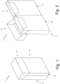
- number 1 denotes as a whole a "book-pack" pack of cigarettes comprising two containers 2 and 3, which house respective wrapped groups of cigarettes, which have respective open upper ends, and are hinged to one another so as to rotate between a closed configuration (illustrated in Figure 1 ), in which the two containers 2 and 3 overlap one another, and an open configuration (illustrated in Figure 2 ), in which the two containers 2 and 3 are separated; moreover, a lid 4 is provided which is hinged to a rear container 2 and, when in a closed position, embraces the upper part of both containers 2 and 3.
- the rear container 2 is larger and houses a larger group of wrapped cigarettes (for example formed by two layers of seven cigarettes each), whereas the front container 3 is smaller and houses a smaller wrapped group of cigarettes (e.g., formed by a single layer of six cigarettes); according to a different embodiment not illustrated, the two containers 2 and 3 have the same size.
- the production of the pack 1 of cigarettes provides for the forming of the two containers 2 and 3 by using two corresponding blanks (not illustrated) which are folded around the respective wrapped groups of cigarettes, coupling (overlapping) the two containers 2 and 3, and then folding a third blank 5 (illustrated in Figure 3 ) around the two coupled (overlapped) containers 2 and 3 which joins the two containers 2 and 3 and forms the common lid 4.
- the pack 1 of cigarettes comprises a bottom wall 6 (illustrated for example in Figure 3 ) which is arranged on the outside, is part of the blank 5, and embraces both containers 2 and 3; namely, the bottom walls of the two containers 2 and 3 rest against the bottom wall 6 which covers the same.
- the bottom wall 6 is glued only to the rear container 2 by means of a glue 7 and therefore the bottom wall 6 has no link (constraint) with the front container 3.
- the bottom wall 6 of the pack 1 of cigarettes is glued only to the rear container 2 by means of the glue 7 applied only on one side and is not glued to the front container 3.
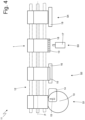
- number 11 denotes as a whole a cutting unit which, in order to make a clear separation between the two containers 2 and 3, makes the cut 8 in the bottom wall 6 of the pack 1 of cigarettes which is fed along a straight path P.
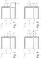
- the cutting unit 11 performs a double cut 8 in the bottom wall 6 of the pack 1 of cigarettes, namely the cut 8 is made along two parallel cutting lines spaced apart from one another and leads to the elimination, from the bottom wall 6, of a strap B or strip (illustrated in Figures 6 and 9 ) between the two cutting lines (the strap B has a width of about 1 mm) ; according to an alternative embodiment, the cutting unit 11 can perform a single cut 8 in the bottom wall 6 of the pack 1 of cigarettes (namely, the cut 8 is made along a single cutting line).
- the cutting unit 11 comprises a belt conveyor 12 which feeds each pack 1 of cigarettes along a straight path P; according to an alternative embodiment not illustrated, the conveyor 12 rotates and feeds each pack 1 of cigarettes along a circular path P.
- the cutting unit 11 comprises a cutting station S1 which is arranged along the path P and is provided with a cutting device 13 which makes the cut 8 in the bottom wall 6 of each pack 1 of cigarettes so as to divide the bottom wall 6 in the rear part 9, which is arranged in the area of the rear container 2 (and that is therefore glued to the rear container 2 by way of the glue 7) and in the front part 10, which is arranged in the area of the front container 3 (and therefore it has no connection with the front container 3 since the glue 7 is applied only in the area of the rear container 2 and therefore only between the rear container 2 and the rear part 9).
- the cutting device 13 comprises two coaxial rotary blades at a given distance from one another which are mounted so as to rotate around the same rotation axis in order to form two parallel and separate cutting lines in the bottom wall 6 of the pack 1 of cigarettes to delimit the strap B which must subsequently be discarded.
- the cutting station S1 is also provided with a sucking device 14 which is configured to suck (namely remove by means of aspiration) the strap B that is separated by the cutting device 13 by means of the double cut 8 (namely along two parallel and separate cutting lines).
- the sucking device 14 comprises a sucking duct (namely, connected to a suction source) designed to suck up the strap B which is separated by the cutting device 13; the function of the sucking duct 14 is to convey by suction the strap B which has been separated from the bottom wall 6 so as to convey the strap B into a suitable collecting area (not illustrated).
- the suction in the sucking duct of the sucking device 14 can be made by using an impeller or a flow accelerator.
- an initial end of the sucking duct of the sucking device 14 has a conical shape having the minimum dimension in the area of the cutting device 13 (namely, having a dimension which progressively widens moving away from the cutting device 13 so as to have the maximum vacuum near the cutting device 13).
- the rear part 9 of the bottom wall 6 remains in its initial position as it is stably glued to the rear container 2 by way of the glue 7; whereas, as the cutting device 13 makes the cut 8 of the bottom wall 6 of the pack 1 of cigarettes, the front part 10 of the bottom wall 6 tends to rise by elastic return with respect to the front container 3 to which it is not in any way constrained (as previously mentioned, no glue is initially applied between the front part 10 and the front container 3) and this lifting of the front part 10 substantially helps the removal of the strap B as it prevents the strap B from being stuck between the two parts 9 and 10.
- the sucking action generated by the sucking device 14 obviously also has an effect on the front part 10 of the bottom wall 6 and contributes in lifting the front part 10 from the front container 3; namely, also the front part 10 of the bottom wall 6 is affected by the suction applied by the sucking device 14 and said suction (pulling the front part 10 of the bottom wall 6 into the sucking device 14) contributes in lifting the front part 10 from the front container 3.
- the sucking action generated by the sucking device 14 obviously also affects the rear part 9 of the bottom wall 6, but the rear part 9 is glued to the rear container 2 and therefore does not move.
- the cutting station S1 can also comprise a blower device 15 which directs a compressed jet of air towards the front part 10 of the bottom wall 6 which forces the front part 10 to lift (namely, forces the front part 10 to move away from the front container 3 and from the rest of the bottom wall 6); the function of the blower device 15 is to help the lifting of the front part 10 of the bottom wall 6 after having made the double cut 8 so as to increase the effect of the natural elastic return of the front part 10.
- a blower device 15 which directs a compressed jet of air towards the front part 10 of the bottom wall 6 which forces the front part 10 to lift (namely, forces the front part 10 to move away from the front container 3 and from the rest of the bottom wall 6); the function of the blower device 15 is to help the lifting of the front part 10 of the bottom wall 6 after having made the double cut 8 so as to increase the effect of the natural elastic return of the front part 10.
- the blank 5 (illustrated in Figure 3 ) is originally completely flat and is subsequently folded around the two containers 2 and 3; therefore, in the absence of an outer constraint, namely, if left free, the various portions of the blank 5 (including the front part 10 of the bottom wall 6) tend to move naturally towards the original flat configuration by elastic return. Consequently, after making the double cut 8, the front part 10 of the bottom wall 6 is free from mechanical constraints and therefore by elastic return it tends spontaneously to move away from the front container 3 and therefore from the rest of the bottom wall 6 (namely from the rear part 9 of the bottom wall 6).
- the blower device 15 can be provided to accentuate by means of a compressed jet of air (and in addition to the action of the sucking device 14) the spontaneous tendency of the front part 10 of the bottom wall 6 to move away from the front container 3.
- the moving away of the front part 10 of the bottom wall 6 from the front container 3 and therefore from the rest of the bottom wall 6 (namely, from the rear part 9 of the bottom wall 6) is essential to "leave-free" the strap B generated by the double cut 8 as it prevents the strap B from getting stuck between the two parts 9 and 10 of the bottom wall 6; once the strap B is no longer held between the two parts 9 and 10 of the bottom wall 6, its removal by means of suction is very simple and reliable.
- the cutting unit 11 comprises a separation station S2 which is arranged along the path P downstream of the cutting station S1 and is provided with a folding device 16 which folds the front part 10 of the bottom wall 6 of each pack 1 of cigarettes so as to move the front part 10 away from the rest of the bottom wall 6 (namely, from the rear part 9).
- the folding device 16 folds the front part 10 of the bottom wall 6 of each pack of cigarettes 1 by about 90° to arrange the front part 10 approximately perpendicular to the rear part 9 (as illustrated in Fig. 7 ).
- the folding device 16 exploits the natural elastic return of the front part 10 of the bottom wall 6 which tends to spontaneously move the front part 10 away from the rest of the bottom wall 6 (namely, from the rear part 9) and comprises a fixed folding helix which pushes the front part 10 of the bottom wall 6 away from the rest of the bottom wall 6.
- the folding device 16 can also comprise a blower which pushes the front part 10 of the bottom wall 6 away from the rest of the bottom wall 6 by means of a compressed jet of air.
- the cutting unit 11 comprises a gluing station S3 which is arranged along the path P downstream of the separation station S2 and is provided with a gluing device 17 which applies glue 18 on the front part 10 of the bottom wall 6 of each pack 1 of cigarettes (as also illustrated in Figure 7 ); the glue 18 can be applied in the form of separate glue dots or in the form of one or more continuous glue strips.
- the glue 18 can be hot (therefore fast-setting), cold (therefore vinyl-based with slower setting) or a combination of hot glue and cold glue.
- the glue 18 is applied to the front part 10 of the bottom wall 6; according to a different embodiment, the glue 18 is applied to the bottom wall of the front container 3 (the important thing is that, ultimately, the glue 18 is interposed between the front part 10 of the bottom wall 6 and the bottom wall of the front container 3).
- the cutting unit 11 comprises a folding station S4 which is arranged along the path P downstream of the gluing station S3 and is provided with a folding device 19 which folds the front part 10 of the bottom wall 6 of each pack 1 of cigarettes against the front container 3 causing the front part 10 of the bottom wall 6 to return to the initial position (as illustrated in Figure 8 ) it had before the cutting station S1 and above all before the separating station S2.
- the folding station S4 the front part 10 of the bottom wall 6 of each pack 1 of cigarettes rests and is therefore glued, by way of the glue 18, to the front container 3 completing (concluding) the manufacturing of the pack 1 of cigarettes.
- the folding device 19 can comprise a fixed folding helix which pushes the front part 10 of the bottom wall 6 against the rest of the pack of cigarettes 1 (namely against the front container 3).
- the cutting unit 11 comprises, furthermore, a control station which could be arranged along the path P downstream of the folding station S4 (but could also be arranged in any other position between the cutting station S1 and the folding station S4) and is provided with a viewing device which, by acquiring and analysing one or more images of the pack 1 of cigarettes, is able to establish whether the strap B produced by the double cut 8 has been correctly eliminated.
- a control station which could be arranged along the path P downstream of the folding station S4 (but could also be arranged in any other position between the cutting station S1 and the folding station S4) and is provided with a viewing device which, by acquiring and analysing one or more images of the pack 1 of cigarettes, is able to establish whether the strap B produced by the double cut 8 has been correctly eliminated.
- any packs 1 of cigarettes that do not conform to the desired specifications namely, in which the strap B produced by the double cut 8 has not been correctly eliminated
- the cutting unit 11 described above has numerous advantages.
- the cutting unit 11 described above allows to ensure the removal of the strap B after the double cut 8 avoiding that the strap B (or a piece of the strap B) can remain in contact with the bottom wall 6 of the pack 1 of cigarettes; this result is obtained due to the fact that after the double cut 8 the front part 10 of the bottom wall 6 moves away from the rear part 9 of the bottom wall 6, thus freeing the strap B (namely, preventing the strap B from remaining "trapped" between the two walls 9 and 10 of the bottom wall 6).
- the strap B produced by the double cut 8 is surely moved away from the bottom wall 6 and therefore easily removed and consequently the correct removal of the strap B produced by the double cut 8 is ensured, thus avoiding that the strap B (or a piece of the strap B) can remain in contact with the bottom wall 6 of the pack 1 of cigarettes.
- the cutting unit 11 described above is simple and inexpensive to implement since, compared to a similar known cutting unit, it requires modifications that are quick to make using commercial pieces or pieces that can be easily obtained with standard machining.
- the cutting unit 11 described above allows the cut 8 of the bottom wall 6 to be made in a very precise and accurate way, always ensuring optimal functionality of the pack 1 of cigarettes.
- the cutting unit 11 described above also allows the cut 8 to be made singularly, since the subsequent "opening" of the front part 10 of the bottom wall 6 always ensures a complete separation between the two parts 9 and 10 of the bottom wall.
Landscapes
- Engineering & Computer Science (AREA)
- Mechanical Engineering (AREA)
- Life Sciences & Earth Sciences (AREA)
- Forests & Forestry (AREA)
- Packaging Of Annular Or Rod-Shaped Articles, Wearing Apparel, Cassettes, Or The Like (AREA)
- Wrapping Of Specific Fragile Articles (AREA)
- Control And Other Processes For Unpacking Of Materials (AREA)
Claims (12)
- Schneidverfahren, um eine Wand (6) einer Packung (1) insbesondere von Rauchwaren zu schneiden; wobei das Schneidverfahren die Schritte umfasst:Bilden in der Wand (6) der Packung (1) eines Schnitts (8), der die Wand (6) in einen ersten Abschnitt (9) und einen zweiten Abschnitt (10) teilt; undAufbringen vor Bilden des Schnitts (8) eines ersten Klebstoffs (7) zwischen dem ersten Abschnitt (9) der Wand (6) und einem ersten Inhalt der Packung (1), um den ersten Abschnitt (9) an den ersten Inhalt zu kleben; wobeidas Schneidverfahren dadurch gekennzeichnet ist, dass es die weiteren Schritte umfasst:Nicht-Aufbringen vor Bilden des Schnitts (8) von Klebstoff zwischen dem zweiten Abschnitt (10) der Wand (6) und einem zweiten Inhalt der Packung (1) undAufbringen, lediglich nachdem der Schnitt (8) gebildet worden ist, eines zweiten Klebstoffs (18) zwischen dem zweiten Abschnitt (10) der Wand (6) und dem zweiten Inhalt der Packung (1), um den zweiten Abschnitt (10) an den zweiten Inhalt zu kleben.
- Schneidverfahren nach Anspruch 1 und umfassend die folgenden weiteren Schritte:Falten, nachdem der Schnitt (8) gebildet worden ist und vor dem Aufbringen des zweiten Klebstoffs (18), des zweiten Abschnitts (10), um den zweiten Abschnitt (10) von dem zweiten Inhalt wegzubewegen;Aufbringen des zweiten Klebstoffs (18), während der zweite Abschnitt (10) von dem zweiten Inhalt getrennt ist; undFalten, nachdem der zweite Klebstoff (18) aufgebracht worden ist, des zweiten Abschnitts (10) gegen den zweiten Inhalt.
- Schneidverfahren nach Anspruch 1 oder 2, wobei der Schnitt (8) ein Doppelschnitt ist, das heißt entlang zweier paralleler Schnittlinien gebildet wird, die voneinander beabstandet sind, und zu der Entfernung eines Streifens (B) führt, der zwischen den zwei Schnittlinien enthalten ist.
- Schneidverfahren nach Anspruch 3 und umfassend den weiteren Schritt des Ausübens von Saugkraft, der konfiguriert ist, den Streifen (B), der durch den Doppelschnitt (8) erzeugt wird, zu entfernen.
- Schneidverfahren nach Anspruch 4, wobei die Saugkraft gleichzeitig mit der Ausführung des Doppelschnitts (8) ausgeübt wird.
- Schneidverfahren nach Anspruch 4 oder 5 und umfassend den weiteren Schritt des Aufbringens eines Druckluftstrahls, der verursacht, dass sich der zweite Abschnitt (10) von dem ersten Abschnitt (9) wegbewegt, gleichzeitig mit der Ausübung der Saugkraft.
- Schneidverfahren nach einem der Ansprüche 1 bis 6, wobei die Packung einen ersten Behälter (2), der den ersten Inhalt bildet, und einen zweiten Behälter (3), der den zweiten Inhalt bildet, umfasst.
- Schneidverfahren nach Anspruch 7, wobei die zwei Behälter (2, 3) aneinander angelenkt sind und der Schnitt (8) der Wand (6) ermöglicht, dass sich die zwei Behälter (2, 3) in Bezug zueinander drehen.
- Schneidverfahren nach einem der Ansprüche 1 bis 8 und umfassend den weiteren Schritt des Zuführens der Packung (1) entlang eines Pfads (P) und durch:eine Schneidstation (S1), die mit einer Schneidvorrichtung (13) versehen ist, die den Schnitt (8) in der Wand (6) der Packung (1) bildet;eine Trennstation (S2), die in dem Pfad (P) stromabwärts der Schneidstation (S1) angeordnet ist und mit einer ersten Faltvorrichtung (16) versehen ist, die den zweiten Abschnitt (10) faltet, um den zweiten Abschnitt (10) von dem Rest der Wand (6) wegzubewegen;eine Klebestation (S3), die entlang des Pfads (P) stromabwärts der Trennstation (S2) angeordnet ist und mit einer Klebevorrichtung (17) versehen ist, die den zweiten Klebstoff (18) auf den zweiten Abschnitt (10) der Wand (6) aufbringt; undeine Faltstation (S4), die entlang des Pfads (P) stromabwärts der Klebestation (S3) angeordnet ist und mit einer zweiten Faltvorrichtung (19) versehen ist, die den zweiten Abschnitt (10) der Wand (6) gegen den zweiten Inhalt faltet, an den er geklebt wird.
- Schneidverfahren nach Anspruch 9, wobei die Schneidstation (S1) mit einer Saugvorrichtung (14) versehen ist, die konfiguriert ist, einen Streifen (B) anzusaugen, der durch die Schneidvorrichtung (13) mittels eines Doppelschnitts (8) getrennt wird.
- Schneidverfahren nach Anspruch 10, wobei die Schneidstation (S1) mit einer Gebläsevorrichtung (15) versehen ist, die einen Druckluftstrahl auf den zweiten Abschnitt (10) richtet, wobei der Druckluftstrahl verursacht, dass der zweite Abschnitt (10) angehoben wird und sich somit vom ersten Abschnitt (9) wegbewegt.
- Schneideinheit (11), um eine Wand (6) einer Packung (1) insbesondere von Rauchwaren zu schneiden; wobei die Schneideinheit (11) eine Schneidvorrichtung (13) umfasst, die konfiguriert ist, in der Wand (6) der Packung (1) einen Schnitt (8) zu bilden, der die Wand (6) in einen ersten Abschnitt (9), der zuvor mittels eines ersten Klebstoffs (7) an einen ersten Inhalt der Packung (1) geklebt wurde, und in einen zweiten Abschnitt (10) teilt;
wobei die Schneideinheit (11) dadurch gekennzeichnet ist, dass sie eine Klebevorrichtung (17) umfasst, die konfiguriert ist, erst nachdem der Schnitt (8) gebildet worden ist, zwischen dem zweiten Abschnitt (10) der Wand (6) und einem zweiten Inhalt der Packung (1) einen zweiten Klebstoff (18) aufzubringen, um den zweiten Abschnitt (10) an den zweiten Inhalt zu kleben.
Applications Claiming Priority (2)
| Application Number | Priority Date | Filing Date | Title |
|---|---|---|---|
| IT102021000030179A IT202100030179A1 (it) | 2021-11-30 | 2021-11-30 | Metodo ed unità di taglio di una parete di un pacchetto |
| PCT/IB2022/061252 WO2023100028A1 (en) | 2021-11-30 | 2022-11-22 | Method and unit to cut a wall of a pack |
Publications (2)
| Publication Number | Publication Date |
|---|---|
| EP4440938A1 EP4440938A1 (de) | 2024-10-09 |
| EP4440938B1 true EP4440938B1 (de) | 2025-05-07 |
Family
ID=80225449
Family Applications (1)
| Application Number | Title | Priority Date | Filing Date |
|---|---|---|---|
| EP22829841.0A Active EP4440938B1 (de) | 2021-11-30 | 2022-11-22 | Verfahren und vorrichtung zum schneiden einer packungswand |
Country Status (5)
| Country | Link |
|---|---|
| EP (1) | EP4440938B1 (de) |
| CN (1) | CN118591495A (de) |
| IT (1) | IT202100030179A1 (de) |
| PL (1) | PL4440938T3 (de) |
| WO (1) | WO2023100028A1 (de) |
Family Cites Families (3)
| Publication number | Priority date | Publication date | Assignee | Title |
|---|---|---|---|---|
| ATE481324T1 (de) * | 2003-12-01 | 2010-10-15 | British American Tobacco Co | Vorrichtung und verfahren zum verpacken von rauchartikeln |
| US6941728B1 (en) * | 2004-03-08 | 2005-09-13 | British American Tobacco (Investments) Limited | Method and apparatus for forming a multiple bundle hinged lid hinged cigarette pack |
| GB0614942D0 (en) * | 2006-07-27 | 2006-09-06 | British American Tobacco Co | Apparatus and method for packing smoking articles |
-
2021
- 2021-11-30 IT IT102021000030179A patent/IT202100030179A1/it unknown
-
2022
- 2022-11-22 CN CN202280079468.7A patent/CN118591495A/zh active Pending
- 2022-11-22 PL PL22829841.0T patent/PL4440938T3/pl unknown
- 2022-11-22 WO PCT/IB2022/061252 patent/WO2023100028A1/en not_active Ceased
- 2022-11-22 EP EP22829841.0A patent/EP4440938B1/de active Active
Also Published As
| Publication number | Publication date |
|---|---|
| WO2023100028A1 (en) | 2023-06-08 |
| EP4440938A1 (de) | 2024-10-09 |
| IT202100030179A1 (it) | 2023-05-30 |
| PL4440938T3 (pl) | 2025-07-21 |
| CN118591495A (zh) | 2024-09-03 |
Similar Documents
| Publication | Publication Date | Title |
|---|---|---|
| EP2874887B2 (de) | Verpackungsverfahren und maschine zur herstellung einer versiegelten packung mit einer gruppe von tabakartikeln | |
| KR101943095B1 (ko) | 담배용 포장용기 및 담배용 포장용기를 생산하는 방법 | |
| EP3196148B1 (de) | Packung für tabakwaren mit einer gesiegelten inneren verpackung | |
| EP3653518B1 (de) | Zuführverfahren und -einheit zum zuführen von zwei verpackungsblättern in einer verpackungsmaschine | |
| EP1616795A1 (de) | Verfahren zur Herstellung von faltbaren Doppel-Klappschachteln | |
| US20170313449A1 (en) | Apparatus and Method for Manufacturing a Smoking Article Pack | |
| EP2740682A2 (de) | Rohling für Klappdeckelpackungen für Rauchartikel und Verfahren zur Herstellung solcher Packungen | |
| US7475525B2 (en) | Method and device for producing packs from at least two partial packs | |
| TW202015975A (zh) | 香煙盒的解包裝置及解包方法 | |
| EP3070006B1 (de) | Verpackungsverfahren und verpackungsmaschine zum falten einer hülle rund um eine gruppe von tabakartikeln | |
| EP4440938B1 (de) | Verfahren und vorrichtung zum schneiden einer packungswand | |
| EP1854724B1 (de) | Verfahren und Maschine zum Herstellen von Zigarettenpackungen | |
| EP4440937B1 (de) | Schneidevorrichtung und verfahren zum entfernen eines bandes von einer packungswand | |
| EP4289752A1 (de) | Verpackungsmaschine und verpackungsverfahren zum verbinden eines inneren rahmens mit zwei gruppen von rauchartikeln | |
| EP4043350B1 (de) | Verpackungsmaschine und verpackungsverfahren zur herstellung einer steifen verpackung für rauchartikel mit versiegelter innerer umhüllung | |
| EP4717613A1 (de) | Verpackungsmaschine und verpackungsverfahren zur herstellung einer steifen verpackung für rauchartikel mit einem klappdeckel | |
| CN116113524B (zh) | 用于从包装盒的壁去除带的切割单元和方法 | |
| WO2001015975A2 (en) | System and method for wrapping articles | |
| CN116323398B (zh) | 用于制造抽吸制品的刚性包装盒的制造方法和机器 | |
| EP1705120A1 (de) | Verfahren und Zuführeinheit für die Zufuhr von Krägen zu einer Verpackungsanlage zum Herstellen von steifen Verpackungen | |
| JP4562073B2 (ja) | 製袋機 | |
| CN120202156A (zh) | 倾斜打开的用于抽吸制品的硬包装 | |
| CN116113524A (zh) | 用于从包装盒的壁去除带的切割单元和方法 | |
| CA3248433A1 (en) | TEAR-OPEN PACKAGING AND ITS PRODUCTION PROCESS | |
| GB2281711A (en) | Feeding blanks for a box comprising two blanks |
Legal Events
| Date | Code | Title | Description |
|---|---|---|---|
| STAA | Information on the status of an ep patent application or granted ep patent |
Free format text: STATUS: UNKNOWN |
|
| STAA | Information on the status of an ep patent application or granted ep patent |
Free format text: STATUS: THE INTERNATIONAL PUBLICATION HAS BEEN MADE |
|
| PUAI | Public reference made under article 153(3) epc to a published international application that has entered the european phase |
Free format text: ORIGINAL CODE: 0009012 |
|
| STAA | Information on the status of an ep patent application or granted ep patent |
Free format text: STATUS: REQUEST FOR EXAMINATION WAS MADE |
|
| 17P | Request for examination filed |
Effective date: 20240524 |
|
| AK | Designated contracting states |
Kind code of ref document: A1 Designated state(s): AL AT BE BG CH CY CZ DE DK EE ES FI FR GB GR HR HU IE IS IT LI LT LU LV MC ME MK MT NL NO PL PT RO RS SE SI SK SM TR |
|
| GRAP | Despatch of communication of intention to grant a patent |
Free format text: ORIGINAL CODE: EPIDOSNIGR1 |
|
| STAA | Information on the status of an ep patent application or granted ep patent |
Free format text: STATUS: GRANT OF PATENT IS INTENDED |
|
| DAV | Request for validation of the european patent (deleted) | ||
| DAX | Request for extension of the european patent (deleted) | ||
| INTG | Intention to grant announced |
Effective date: 20241128 |
|
| GRAS | Grant fee paid |
Free format text: ORIGINAL CODE: EPIDOSNIGR3 |
|
| P01 | Opt-out of the competence of the unified patent court (upc) registered |
Free format text: CASE NUMBER: APP_8242/2025 Effective date: 20250218 |
|
| GRAA | (expected) grant |
Free format text: ORIGINAL CODE: 0009210 |
|
| STAA | Information on the status of an ep patent application or granted ep patent |
Free format text: STATUS: THE PATENT HAS BEEN GRANTED |
|
| AK | Designated contracting states |
Kind code of ref document: B1 Designated state(s): AL AT BE BG CH CY CZ DE DK EE ES FI FR GB GR HR HU IE IS IT LI LT LU LV MC ME MK MT NL NO PL PT RO RS SE SI SK SM TR |
|
| REG | Reference to a national code |
Ref country code: GB Ref legal event code: FG4D |
|
| REG | Reference to a national code |
Ref country code: CH Ref legal event code: EP |
|
| REG | Reference to a national code |
Ref country code: DE Ref legal event code: R096 Ref document number: 602022014457 Country of ref document: DE |
|
| REG | Reference to a national code |
Ref country code: IE Ref legal event code: FG4D |
|
| REG | Reference to a national code |
Ref country code: NL Ref legal event code: FP |
|
| PG25 | Lapsed in a contracting state [announced via postgrant information from national office to epo] |
Ref country code: PT Free format text: LAPSE BECAUSE OF FAILURE TO SUBMIT A TRANSLATION OF THE DESCRIPTION OR TO PAY THE FEE WITHIN THE PRESCRIBED TIME-LIMIT Effective date: 20250908 Ref country code: ES Free format text: LAPSE BECAUSE OF FAILURE TO SUBMIT A TRANSLATION OF THE DESCRIPTION OR TO PAY THE FEE WITHIN THE PRESCRIBED TIME-LIMIT Effective date: 20250507 Ref country code: FI Free format text: LAPSE BECAUSE OF FAILURE TO SUBMIT A TRANSLATION OF THE DESCRIPTION OR TO PAY THE FEE WITHIN THE PRESCRIBED TIME-LIMIT Effective date: 20250507 |
|
| REG | Reference to a national code |
Ref country code: LT Ref legal event code: MG9D |
|
| PG25 | Lapsed in a contracting state [announced via postgrant information from national office to epo] |
Ref country code: NO Free format text: LAPSE BECAUSE OF FAILURE TO SUBMIT A TRANSLATION OF THE DESCRIPTION OR TO PAY THE FEE WITHIN THE PRESCRIBED TIME-LIMIT Effective date: 20250807 Ref country code: GR Free format text: LAPSE BECAUSE OF FAILURE TO SUBMIT A TRANSLATION OF THE DESCRIPTION OR TO PAY THE FEE WITHIN THE PRESCRIBED TIME-LIMIT Effective date: 20250808 |
|
| REG | Reference to a national code |
Ref country code: AT Ref legal event code: MK05 Ref document number: 1792261 Country of ref document: AT Kind code of ref document: T Effective date: 20250507 |
|
| PG25 | Lapsed in a contracting state [announced via postgrant information from national office to epo] |
Ref country code: BG Free format text: LAPSE BECAUSE OF FAILURE TO SUBMIT A TRANSLATION OF THE DESCRIPTION OR TO PAY THE FEE WITHIN THE PRESCRIBED TIME-LIMIT Effective date: 20250507 |
|
| PG25 | Lapsed in a contracting state [announced via postgrant information from national office to epo] |
Ref country code: HR Free format text: LAPSE BECAUSE OF FAILURE TO SUBMIT A TRANSLATION OF THE DESCRIPTION OR TO PAY THE FEE WITHIN THE PRESCRIBED TIME-LIMIT Effective date: 20250507 |
|
| PG25 | Lapsed in a contracting state [announced via postgrant information from national office to epo] |
Ref country code: AT Free format text: LAPSE BECAUSE OF FAILURE TO SUBMIT A TRANSLATION OF THE DESCRIPTION OR TO PAY THE FEE WITHIN THE PRESCRIBED TIME-LIMIT Effective date: 20250507 |
|
| PG25 | Lapsed in a contracting state [announced via postgrant information from national office to epo] |
Ref country code: RS Free format text: LAPSE BECAUSE OF FAILURE TO SUBMIT A TRANSLATION OF THE DESCRIPTION OR TO PAY THE FEE WITHIN THE PRESCRIBED TIME-LIMIT Effective date: 20250807 |
|
| PG25 | Lapsed in a contracting state [announced via postgrant information from national office to epo] |
Ref country code: IS Free format text: LAPSE BECAUSE OF FAILURE TO SUBMIT A TRANSLATION OF THE DESCRIPTION OR TO PAY THE FEE WITHIN THE PRESCRIBED TIME-LIMIT Effective date: 20250907 |
|
| PG25 | Lapsed in a contracting state [announced via postgrant information from national office to epo] |
Ref country code: LV Free format text: LAPSE BECAUSE OF FAILURE TO SUBMIT A TRANSLATION OF THE DESCRIPTION OR TO PAY THE FEE WITHIN THE PRESCRIBED TIME-LIMIT Effective date: 20250507 |
|
| PGFP | Annual fee paid to national office [announced via postgrant information from national office to epo] |
Ref country code: NL Payment date: 20251126 Year of fee payment: 4 |
|
| PGFP | Annual fee paid to national office [announced via postgrant information from national office to epo] |
Ref country code: DE Payment date: 20251128 Year of fee payment: 4 |
|
| PG25 | Lapsed in a contracting state [announced via postgrant information from national office to epo] |
Ref country code: DK Free format text: LAPSE BECAUSE OF FAILURE TO SUBMIT A TRANSLATION OF THE DESCRIPTION OR TO PAY THE FEE WITHIN THE PRESCRIBED TIME-LIMIT Effective date: 20250507 Ref country code: SM Free format text: LAPSE BECAUSE OF FAILURE TO SUBMIT A TRANSLATION OF THE DESCRIPTION OR TO PAY THE FEE WITHIN THE PRESCRIBED TIME-LIMIT Effective date: 20250507 |
|
| PGFP | Annual fee paid to national office [announced via postgrant information from national office to epo] |
Ref country code: IT Payment date: 20251201 Year of fee payment: 4 |
|
| PG25 | Lapsed in a contracting state [announced via postgrant information from national office to epo] |
Ref country code: CZ Free format text: LAPSE BECAUSE OF FAILURE TO SUBMIT A TRANSLATION OF THE DESCRIPTION OR TO PAY THE FEE WITHIN THE PRESCRIBED TIME-LIMIT Effective date: 20250507 |
|
| PGFP | Annual fee paid to national office [announced via postgrant information from national office to epo] |
Ref country code: PL Payment date: 20251031 Year of fee payment: 4 |
|
| PG25 | Lapsed in a contracting state [announced via postgrant information from national office to epo] |
Ref country code: EE Free format text: LAPSE BECAUSE OF FAILURE TO SUBMIT A TRANSLATION OF THE DESCRIPTION OR TO PAY THE FEE WITHIN THE PRESCRIBED TIME-LIMIT Effective date: 20250507 |
|
| PG25 | Lapsed in a contracting state [announced via postgrant information from national office to epo] |
Ref country code: SK Free format text: LAPSE BECAUSE OF FAILURE TO SUBMIT A TRANSLATION OF THE DESCRIPTION OR TO PAY THE FEE WITHIN THE PRESCRIBED TIME-LIMIT Effective date: 20250507 |
|
| REG | Reference to a national code |
Ref country code: DE Ref legal event code: R097 Ref document number: 602022014457 Country of ref document: DE |
|
| PLBE | No opposition filed within time limit |
Free format text: ORIGINAL CODE: 0009261 |
|
| STAA | Information on the status of an ep patent application or granted ep patent |
Free format text: STATUS: NO OPPOSITION FILED WITHIN TIME LIMIT |
|
| PG25 | Lapsed in a contracting state [announced via postgrant information from national office to epo] |
Ref country code: RO Free format text: LAPSE BECAUSE OF FAILURE TO SUBMIT A TRANSLATION OF THE DESCRIPTION OR TO PAY THE FEE WITHIN THE PRESCRIBED TIME-LIMIT Effective date: 20250507 |
|
| REG | Reference to a national code |
Ref country code: CH Ref legal event code: L10 Free format text: ST27 STATUS EVENT CODE: U-0-0-L10-L00 (AS PROVIDED BY THE NATIONAL OFFICE) Effective date: 20260318 |
|
| 26N | No opposition filed |
Effective date: 20260210 |