EP4440431B1 - Hämolysereduktionszubehör zur direkten blutentnahme - Google Patents
Hämolysereduktionszubehör zur direkten blutentnahme Download PDFInfo
- Publication number
- EP4440431B1 EP4440431B1 EP22844355.2A EP22844355A EP4440431B1 EP 4440431 B1 EP4440431 B1 EP 4440431B1 EP 22844355 A EP22844355 A EP 22844355A EP 4440431 B1 EP4440431 B1 EP 4440431B1
- Authority
- EP
- European Patent Office
- Prior art keywords
- fluid passage
- insert body
- opening
- flow restriction
- restriction device
- Prior art date
- Legal status (The legal status is an assumption and is not a legal conclusion. Google has not performed a legal analysis and makes no representation as to the accuracy of the status listed.)
- Active
Links
Images



Classifications
-
- A—HUMAN NECESSITIES
- A61—MEDICAL OR VETERINARY SCIENCE; HYGIENE
- A61B—DIAGNOSIS; SURGERY; IDENTIFICATION
- A61B5/00—Measuring for diagnostic purposes; Identification of persons
- A61B5/15—Devices for taking samples of blood
- A61B5/150007—Details
-
- A—HUMAN NECESSITIES
- A61—MEDICAL OR VETERINARY SCIENCE; HYGIENE
- A61B—DIAGNOSIS; SURGERY; IDENTIFICATION
- A61B5/00—Measuring for diagnostic purposes; Identification of persons
- A61B5/15—Devices for taking samples of blood
- A61B5/150007—Details
- A61B5/150015—Source of blood
- A61B5/15003—Source of blood for venous or arterial blood
-
- A—HUMAN NECESSITIES
- A61—MEDICAL OR VETERINARY SCIENCE; HYGIENE
- A61B—DIAGNOSIS; SURGERY; IDENTIFICATION
- A61B5/00—Measuring for diagnostic purposes; Identification of persons
- A61B5/15—Devices for taking samples of blood
- A61B5/150007—Details
- A61B5/150206—Construction or design features not otherwise provided for; manufacturing or production; packages; sterilisation of piercing element, piercing device or sampling device
-
- A—HUMAN NECESSITIES
- A61—MEDICAL OR VETERINARY SCIENCE; HYGIENE
- A61B—DIAGNOSIS; SURGERY; IDENTIFICATION
- A61B5/00—Measuring for diagnostic purposes; Identification of persons
- A61B5/15—Devices for taking samples of blood
- A61B5/150007—Details
- A61B5/150732—Needle holders, for instance for holding the needle by the hub, used for example with double-ended needle and pre-evacuated tube
-
- A—HUMAN NECESSITIES
- A61—MEDICAL OR VETERINARY SCIENCE; HYGIENE
- A61B—DIAGNOSIS; SURGERY; IDENTIFICATION
- A61B5/00—Measuring for diagnostic purposes; Identification of persons
- A61B5/15—Devices for taking samples of blood
- A61B5/150007—Details
- A61B5/150946—Means for varying, regulating, indicating or limiting the speed or time of blood collection
-
- A—HUMAN NECESSITIES
- A61—MEDICAL OR VETERINARY SCIENCE; HYGIENE
- A61B—DIAGNOSIS; SURGERY; IDENTIFICATION
- A61B5/00—Measuring for diagnostic purposes; Identification of persons
- A61B5/15—Devices for taking samples of blood
- A61B5/150992—Blood sampling from a fluid line external to a patient, such as a catheter line, combined with an infusion line; Blood sampling from indwelling needle sets, e.g. sealable ports, luer couplings or valves
-
- A—HUMAN NECESSITIES
- A61—MEDICAL OR VETERINARY SCIENCE; HYGIENE
- A61B—DIAGNOSIS; SURGERY; IDENTIFICATION
- A61B5/00—Measuring for diagnostic purposes; Identification of persons
- A61B5/15—Devices for taking samples of blood
- A61B5/153—Devices specially adapted for taking samples of venous or arterial blood, e.g. with syringes
-
- A—HUMAN NECESSITIES
- A61—MEDICAL OR VETERINARY SCIENCE; HYGIENE
- A61B—DIAGNOSIS; SURGERY; IDENTIFICATION
- A61B5/00—Measuring for diagnostic purposes; Identification of persons
- A61B5/15—Devices for taking samples of blood
- A61B5/153—Devices specially adapted for taking samples of venous or arterial blood, e.g. with syringes
- A61B5/1535—Devices specially adapted for taking samples of venous or arterial blood, e.g. with syringes comprising means for indicating vein or arterial entry
-
- A—HUMAN NECESSITIES
- A61—MEDICAL OR VETERINARY SCIENCE; HYGIENE
- A61M—DEVICES FOR INTRODUCING MEDIA INTO, OR ONTO, THE BODY; DEVICES FOR TRANSDUCING BODY MEDIA OR FOR TAKING MEDIA FROM THE BODY; DEVICES FOR PRODUCING OR ENDING SLEEP OR STUPOR
- A61M5/00—Devices for bringing media into the body in a subcutaneous, intra-vascular or intramuscular way; Accessories therefor, e.g. filling or cleaning devices, arm-rests
- A61M5/14—Infusion devices, e.g. infusing by gravity; Blood infusion; Accessories therefor
- A61M5/168—Means for controlling media flow to the body or for metering media to the body, e.g. drip meters, counters ; Monitoring media flow to the body
- A61M5/16804—Flow controllers
Definitions
- the present invention relates to a flow restriction device according to the preamble of claim 1.
- a flow restriction device is known from US 2021/228127 A1 .
- the present disclosure generally relates to blood draw and administration of parenteral fluids to a patient, and particularly to systems and non claimed methods to reduce hemolysis in PIVC blood draw using a flow restriction device.
- a clinician In order to verify proper placement of the introducer needle and/or the catheter in the blood vessel, a clinician generally confirms that there is "flashback" of blood in a flashback chamber of the catheter assembly. Once placement of the needle has been confirmed, the clinician may temporarily occlude flow in the vasculature and remove the needle, leaving the catheter in place for future blood withdrawal or fluid infusion.
- the blood collection container may be coupled to the catheter.
- a pressure in the vein is higher than a pressure in the blood collection container, which pushes blood into the blood collection container, thus filling the blood collection container with blood.
- a vacuum within the blood collection container decreases as the blood collection container fills, until the pressure in the blood collection container equalizes with the pressure in the vein, and the flow of blood stops.
- red blood cells are in a high shear stress state and susceptible to hemolysis due to a high initial pressure differential between the vein and the blood collection container. Hemolysis may result in rejection and discard of a blood sample. The high initial pressure differential can also result in catheter tip collapse, vein collapse, or other complications that prevent or restrict blood from filling the blood collection container. Furthermore, blood spillage during and/or after blood draw commonly occurs.
- the document US 2015 011 847 A1 describes a blood-sampling tube that includes a first fluid-receiving chamber designed to receive fluid. This chamber is connected to at least one fluid channel.
- the fluid channel is equipped with a sensor device capable of measuring at least one biochemical function of the fluid passing through. The measurements taken by the sensor device can be accessed via a data interface integrated into the blood-sampling tube.
- the document US 2021 228 127 A1 describes an adapter featuring a distal end designed to couple with a catheter assembly and a proximal end equipped with a proximal connector for coupling to a blood collection device. Between the distal and proximal ends, a fluid pathway is present. This fluid pathway includes a non-linear portion, which can take on various shapes such as a coil, an S-shape, or other configurations.
- the present disclosure provides a flow restriction device, comprising a housing comprising a first end portion, a second end portion, an inner surface forming a cavity between the first and second end portions, a first opening through the first end portion, and a second opening through the second end portions, and an insert body comprising a first end, a second end, an outer surface extending between the first and second ends, and an inner surface forming a fluid passage extending between the first and second ends, the fluid passage having a first opening through the first end of the insert body, a second opening through the second end of the insert body, and a third opening through the outer surface, wherein the insert body is positioned within the cavity with the first opening of the fluid passage fluidly coupled with the first opening of the housing, the second opening of the fluid passage fluidly coupled with the second opening of the housing, and the third opening obstructed by the inner surface of the housing.
- the present disclosure provides a peripheral intravenous catheter assembly configured to limit hemolysis during the drawing of blood from a patient, comprising a flow restriction device, comprising, a housing comprising a first end portion a first end portion, a second end portion, an inner surface forming a cavity between the first and second end portions, a first opening through the first end portion, wherein the first end portion is configured to couple to a catheter assembly, and the second end portion is configured to couple to a fluid collection device, an insert body comprising a first end, a second end, a longitudinal axis extending through the first and second ends, and an inner surface forming a fluid passage extending between the first and second ends, the fluid passage comprising a first portion that extends in a first direction away from the longitudinal axis, a second portion that extends in a second direction toward the longitudinal axis, and a third portion that extends in the first direction, wherein the insert body is positioned within the cavity with a first opening of the fluid passage fluidly coupled with the first opening
- Blood draw via a vascular access device has drawn increasing attention attributed to minimized needle sticks and improved operation efficiency as compared with traditional blood draw methods with venipuncture.
- Current blood draw using a peripheral intravenous catheter (PIVC) has seen some challenges, one of the most critical is hemolysis related blood quality.
- PIVC peripheral intravenous catheter
- the standard connection such as a short extension set and a needleless connector
- blood collection devices such as a Vacutainer
- Various embodiments of the present disclosure are directed to providing systems and non claimed methods to address hemolysis in PIVC blood draw with a hemolysis reduction accessory (also referred to herein as a flow restriction device) which can be pre-attached to the PIVC and decrease a flow rate to reduce a risk of hemolysis.
- a hemolysis reduction accessory also referred to herein as a flow restriction device
- the hemolysis-reduction accessory is advantageously compatible with PIVC placement and does not necessitate change to any of the existing operations.
- the hemolysis-reduction accessory of the various embodiments described herein is potentially applicable to a wide variety of PIVC products, and compatible with existing blood collection devices and infusion disposables.
- Various embodiments of the present disclosure focus on effective flow rate reduction with the add-on hemolysis-reduction accessory (also referred to herein as a flow restriction device) that regulates the overall flow rate of the entire fluid path as blood cells travel through.
- the flow restriction device can be either assembled with the PIVC or co-packaged with the PIVC. As such, there is no additional operation during catheter placement since the device can permit blood flashback.
- the clinician may connect a blood collection device to a port or opening of the accessory and can then draw blood to the intended volume. After blood draw, the clinician may disconnect and discard the flow restriction device and the blood collection device together. As such, this flow restriction device can be either for single blood draw or stay inline throughout indwell.
- the flow restriction devices and associated blood collection systems of the various embodiments described herein additionally provide further advantages over currently existing blood collection systems.
- add-on flow restriction devices described herein allow for hemolysis-reduction function to be integrated for PIVC blood draw.
- the flow restriction devices described herein are compatible with PIVC placement and allow for seamless blood draw at insertion. Additionally, since the flow restriction devices are an add-on which can be easily incorporated without any changes to existing PIVC, there is minimal impact to clinical setting and operations.
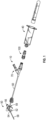
- FIG. 1 illustrates a vascular access device 10 including a peripheral intravenous catheter (PIVC) assembly 50 that includes a flow restriction device 100, in accordance with some embodiments of the present disclosure.
- the flow restriction device 100 may be configured to reduce a likelihood of hemolysis during blood collection using the vascular access device 10.
- the vascular access device 10 may include a catheter assembly 50.
- the catheter assembly 50 may include a catheter hub 52, which may include a distal end 54, a proximal end 56, and a lumen extending through the distal end and the proximal end.
- the catheter assembly 50 may further include a catheter 58, which may be secured within the catheter hub 52 and may extend distally from the distal end 54 of the catheter hub 52.
- the catheter assembly 50 may be a peripheral intravenous catheter (PIVC).
- PIVC peripheral intravenous catheter
- the catheter assembly 50 may include or correspond to any suitable catheter assembly 50.
- the catheter assembly 50 may be integrated and include an extension tube 60, which may extend from and be integrated with a side port 59 of the catheter hub 52.
- an integrated catheter assembly is the BD NEXIVA TM Closed IV Catheter system, available from Becton Dickinson and Company.
- a proximal end of the extension tube 60 may be coupled to an adapter, such as, for example, a Y-adapter 70.
- the flow restriction device 100 may be fluidly coupled to the Y-adapter 70.
- the catheter assembly 50 may be non-integrated and may not include the extension tube 60.
- the flow restriction device 100 may be configured to couple to the proximal end 56 of the catheter hub 52 or another suitable portion of the catheter assembly 50. In some embodiments, the flow restriction device 100 may be coupled directly to the catheter assembly 50, eliminating the extension tube 60 and providing a compact catheter system.
- FIG. 2 illustrates a perspective view of a flow restriction device 100, in accordance with some embodiments of the present disclosure.
- FIG. 3 illustrates an exploded view of the flow restriction device 100 having a housing with a first end portion and a second end portion, and an insert body.
- FIG. 4 illustrates a perspective view of the insert body 106 of FIG. 3 .
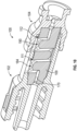
- FIGS. 5A and 5B illustrate a cross-sectional view of the flow restriction device of FIG. 2 , along line 5-5.
- the flow restriction device 100 includes housing 148 with a first end portion 150 and a second end portion 110.
- the first end portion 150 can be configured to couple to the catheter assembly 50, and the second end portion 110 can be configured to couple to fluid collection device, such as a blood collection device 40.
- the second end portion 110 may be integrated with the blood collection device 40 or monolithically formed with the blood collection device 40 as a single unit or piece.
- the second end portion 110 may be in the form of a female luer connector or another suitable connector, which may be coupled with a male luer portion of the blood collection device 40.
- the first end portion 150 may be in the form of a male luer connector or another suitable connector, which may be coupled with a catheter or a portion of catheter assembly.
- the first end portion 150 may have an internal surface 156 forming a first opening 154.
- the second end portion 110 may include an internal surface 115 forming a second opening 114 extending therethrough for coupling to a male luer portion of the blood collection device 40.
- the second opening of the 114 of the second end portion may be fluidly connected to the first opening 154 of the first end portion via a cavity 140 formed by an inner surface of the housing.
- the first end portion 150 of the housing can be formed as any of a male and/or female luer connector with the first opening 154 extending therethrough, and the second end portion 110 of the housing can be formed as the other of a male and/or female luer connector with the second opening 114 extending therethrough.
- the housing 148 can comprise a material that includes a thermoplastic polymer such as a polycarbonate or another material having similar properties.
- the first end portion 150 can be integrally formed with the housing 148 to form a single monolithic piece, and the housing 148 can be coupled to the second end portion 110.
- the first opening 154 of the first end portion is fluidly coupled to the second opening of the second end portion through the cavity 140.
- the cavity 140 is configured to receive an insert body 106 therein.
- the insert body 106 directs a fluid flow between the first and second openings 154, 114 of the housing while inducing a resistance to the fluid flow as it moves through the insert body 106. By inducing a resistance to the fluid flow, the rate of fluid flow is reduced as the fluid moves through the insert body 106. Reducing the flow rate of a fluid, such as blood, through the flow restriction device 100 can reduce the hemolysis index of the blood.
- the insert body 106 has a first end 164, a second end 166, and an inner surface 168 forming a fluid passage 170 that extends through the first and second ends 164, 166.
- the fluid passage 170 extends along a path between the first and second ends 164, 166 of the body, which is configured to reduce a rate of fluid flow through the insert body 106.
- a perspective view of the insert body 106 is illustrated in FIG. 4 with the body shown as being transparent to permit the fluid passage 170 to be visible in conjunction with the present disclosure.
- the first end 164 of the insert body and the second end 166 of the insert body form proximal-most and distal-most surfaces of the body, respectively.
- the insert body 106 can also define a longitudinal axis A1 that extends through the first and second ends 164, 166.
- the fluid passage 170 spans between the first and second ends 164, 166 of the insert body, and is configured to extend in more than one direction along a path between the first and second ends 164, 166. Because the path extends in more than one direction, the fluid passage 170 extends indirectly between the first and second ends 164, 166 of the insert body.
- the indirect path between the first and second ends 164, 166 of the body can have a length that is greater than a distance between the first and second ends 164, 166 of the body.
- the fluid passage 170 includes a first opening 180 through the first end 164 of the insert body, and a second opening 182 through the second end 166 of the insert body. Between the first and second openings 180, 182, the fluid passage 170 can include a third opening 184 through an outer surface 186 of the insert body.
- the third opening 184 extends through the outer surface 186 at a location that is between the first and second ends 164, 166.
- the location of the third opening 184 can be spaced apart from the first and second ends 164, 166 such that an outermost circumference of any of the first and second ends 164, 166 is uninterrupted by the third opening 184.
- the fluid passage 170 can also include a fourth opening 188 through the outer surface 186 of the insert body.
- the third and fourth openings 184, 188 are positioned along the outer surface 186 of the insert body relative to the longitudinal axis A1.
- the third and fourth openings 184, 188 are positioned along the outer surface 186 of the insert body such that the third and fourth openings 184, 188 are spaced apart in a radial direction around the longitudinal axis A1 of the insert body.
- the third and fourth openings 184, 188 can be spaced apart by an angle of between approximately 10 degrees and approximately 180 degrees, relative to the longitudinal axis A1.
- the third and fourth openings 184, 188 are spaced apart by an angle of approximately 180 degrees.
- the fluid passage 170 can also include a fifth opening 190 through the outer surface 186 of the insert body.
- the third and fifth openings 184, 190 can be spaced apart in a direction along the longitudinal axis A1 of the insert body, with the fourth opening 188 positioned between the third and fifth openings 184, 190.
- the insert body 106 can be configured with the third, fourth, and fifth openings 184, 188, 190 positioned in any radial orientation relative to each other.
- the third and fifth openings 184, 190 are radially aligned relative to the longitudinal axis A1
- the fourth opening 188 is spaced apart in a radial direction around the longitudinal axis A1 by an angle.
- the fourth opening 188 can be spaced apart from any of the third and fifth openings 184, 190 by an angle of between approximately 10 degrees and approximately 180 degrees.
- the fourth opening 188 is spaced apart of the third and fifth openings 184, 190 by an angle of approximately 180 degrees.
- the fluid passage 170 can include a first portion 172 that extends in a first direction D1 away from the longitudinal axis A1.
- a second portion 174 of the fluid passage extends from the first portion 172 in a second direction D2 toward the longitudinal axis A1.
- the second portion 174 of the fluid passage can extend past the longitudinal axis A1, and a third portion of the fluid passage can extend from the second portion 174 in the first direction D1 toward the longitudinal axis A1.
- the fluid passage 170 comprises a fourth portion 178 that extends from the third portion 176 in a second direction D2 toward the longitudinal axis A1.
- the second opening 182 of the fluid passage is fluidly coupled to the fourth portion 178.
- the change in direction of the fluid passage 170 between the first and second ends 164, 166 of the insert body can be configured by an angle between one or more portion of the fluid passage 170.
- the fluid passage 170 can have a change in direction by an angle between approximately 45 degrees and approximately 90 degrees.
- the changes in direction of the fluid passage 170 can form a line that represents a periodic wave, such as a square wave.
- the changes in direction of the fluid passage are optimized to reduce pressure of a fluid, e.g., blood, moving through the fluid passage 170 by inducing resistance to the fluid. Since the decreased blood flow rate causes a reduction in shear stress experienced by the red blood cells of the blood, a risk of hemolysis during blood collection may advantageously be reduced.
- the fluid passage 170 includes eight changes in direction, where each change in direction is approximately 90 degrees. Referring to FIGS. 5A and 5B , an angle between any of the first, second, third, and fourth portions 172, 174, 176, 178, and any of the third, fourth, and fifth openings 184, 188, 190 of the fluid passage 170 is illustrated as approximately 90 degrees.
- An angle AA between the fluid passage 170 at the first opening 180 and the first portion 172 is approximately 90 degrees
- an angle AB between the first portion 172 and the fluid passage 170 along the first opening 180 is approximately 90 degrees
- an angle AC between the fluid passage 170 along the third opening 184 and the second portion 174 is approximately 90 degrees
- an angle AD between the second portion 174 and the fluid passage 170 along the fourth opening 188 is approximately 90 degrees
- an angle AE between the fluid passage 170 along the fourth opening 188 and the third portion 176 is approximately 90 degrees
- an angle AF between the third portion 176 and the fluid passage 170 along the fifth opening 190 is approximately 90 degrees
- an angle AG between the fluid passage 170 along the fifth opening 190 and the fourth portion 178 is approximately 90 degrees
- an angle AE between the fourth portion 178 and the fluid passage 170 at the second opening 182 is approximately 90 degrees.
- FIG. 5B movement of a fluid through the flow restriction device 100 and along the path of the fluid passage 170 is illustrated by arrows. Although the arrows illustrate movement of a fluid through the flow restriction device 100 in a direction from the first end portion 150 to the second end portion 110, it should be understood that the present disclosure contemplates that a fluid can move through the flow restriction device 100 in a direction from the second end portion 110 to the first end portion 150.
- the insert body 106 When the insert body 106 is positioned within the cavity 140 of the housing, at least a portion of the outer surface 186 of the insert body engages against the inner surface of the housing that forms the cavity 140.
- a segment of the fluid passage 170 at any of the third, fourth, and fifth openings 184, 188, 190 is at least partially formed by the inner surface of the housing 148.
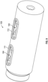
- the housing 148 can comprise a transparent material to permit observation of a fluid in the fluid passage 170.
- a housing comprising a transparent material is illustrated in FIG. 6 , where the third opening 184, the fourth opening 188 (not shown), and the fifth opening 190 of the fluid passage are visible through the outer surface of the housing.
- a portion of the housing 148 comprises a transparent material forming a window through the housing.
- the window can be positioned between the first and second openings 154, 114 of the housing, at a location the is aligned with any of the third, fourth, and fifth openings 184, 188, 190 of the insert body positioned in the cavity 140 of the housing.
- the housing 148 comprises three windows, each aligned with a respective one of the third, fourth, and fifth openings 184, 188, 190 of the insert body.
- the window can extend around a circumference of the housing such that the third, fourth, and/or fifth openings 184, 188, 190 are each longitudinally aligned a window in any rotational orientation of the insert body relative to the housing.
- An insert body 107 can be configured, in some embodiments of the present disclosure, to include a material that is flexible, relative to other portions of the insert body or the housing.
- the flexible material can provide a seal between the insert body and the housing.
- the insert body 107 can be partially or entirely formed of the flexible material, or the insert body 107 is over-molded with the flexible material.
- the flexible material is an elastomer, such as silicone rubber, or a similar material that can provide a fluid seal between the insert body and the housing.
- an insert body 107 formed of a silicone material is illustrated.
- the silicone extends along the outer surface of the insert body 107 and can engage against an inner surface of the housing 148 when the insert body 107 is positioned with in the cavity 140 of the housing.
- Engagement of the silicone 108 against the inner surface of the housing 148, as illustrated in FIG. 8 provides a seal that can resist a fluid from moving out of an opening of the fluid passage 170, such as the third, fourth, and fifth openings 184, 188, 190.
- an insert body 109 can include a wall 111 that extends in a direction away from the outer surface of the insert body, as illustrated in FIG. 9 .
- the wall 111 is configured to engage against an inner surface of the housing 148 when the insert body 109 is positioned with in the cavity 140 of the housing to provide a seal that resists a fluid from moving out of an opening of the fluid passage 170.
- the wall 111 is positioned to extend around an opening of the fluid passage 170, such as the third, fourth, and fifth openings 184, 188, 190.
- the wall 111 can have a height that extends in a direction away from an outer surface of the insert body, and a length that extends around the opening of the fluid passage 170.
- the insert body 109 includes a first wall 111 that extends around the third opening 184 of the insert body, a second wall 112 that extends around the fifth opening 190 of the insert body, and a third wall that extends around the fourth opening of the insert body.
- any of the walls 111, 112 of the insert body can engage against an inner surface of the housing 148 to resist a fluid from moving out of an opening of the fluid passage 170, such as the third, fourth, and fifth openings 184, 188, 190.
- a wall 111, 112 is compressed or crushed when the insert body 109 is positioned in the housing 148.
- each core pin comprises two protrusions, where each protrusion is configured to form at least a portion of the fluid passage 170.
- first and second core pins C1, C2 can be positioned in a mold to form the first and second openings 180, 182, respectively.
- a third core pin C3 can be positioned between the first and second core pins C1, C2 in the mold to form the first portion 172, the third opening 184 of the insert body, and the second portion 174 of the fluid passage.
- a fourth core pin C4 can be positioned in the mold to form the second portion 174, the fourth opening 188, and the third portion 176 of the fluid passage.
- a fifth core pin C5 can be positioned in the mold to form the third portion 176, the fifth opening 190, and the fourth portion 178 of fourth portion 178.'
Landscapes
- Health & Medical Sciences (AREA)
- Life Sciences & Earth Sciences (AREA)
- Engineering & Computer Science (AREA)
- Molecular Biology (AREA)
- Animal Behavior & Ethology (AREA)
- Pathology (AREA)
- Physics & Mathematics (AREA)
- Biomedical Technology (AREA)
- Heart & Thoracic Surgery (AREA)
- Medical Informatics (AREA)
- Hematology (AREA)
- Surgery (AREA)
- Biophysics (AREA)
- General Health & Medical Sciences (AREA)
- Public Health (AREA)
- Veterinary Medicine (AREA)
- Manufacturing & Machinery (AREA)
- Vascular Medicine (AREA)
- Infusion, Injection, And Reservoir Apparatuses (AREA)
- Measurement Of The Respiration, Hearing Ability, Form, And Blood Characteristics Of Living Organisms (AREA)
- External Artificial Organs (AREA)
Claims (13)
- Durchflussbegrenzungsvorrichtung (100), umfassend:ein Gehäuse (148) mit einem ersten Endabschnitt (150), einem zweiten Endabschnitt (110), einer Innenfläche, die einen Hohlraum (140) zwischen dem ersten und zweiten Endabschnitt bildet, einer ersten Öffnung (154) durch den ersten Endabschnitt und einer zweiten Öffnung (114) durch den zweiten Endabschnitt; undeinen Einsetzkörper (106, 107, 109) mit einem ersten Ende (164), einem zweiten Ende (166), einer Längsachse (A1), die sich durch das erste und zweite Ende erstreckt, und einer Innenfläche (168), die einen Fluidkanal (170) bildet, der sich zwischen dem ersten und zweiten Ende erstreckt, wobei der Fluidkanal einen ersten Abschnitt (172), der sich in einer ersten Richtung (D1) von der Längsachse (A1) weg erstreckt, einen zweiten Abschnitt (174), der sich in einer zweiten Richtung (D2) zur Längsachse (A1) hin erstreckt, einen dritten Abschnitt (176), der sich in der ersten Richtung (D1) erstreckt, umfasst;wobei der Einsetzkörper (106, 107, 109) innerhalb des Hohlraums (140) positioniert ist, wobei eine erste Öffnung (180) des Fluidkanals mit der ersten Öffnung (154) des Gehäuses und eine zweite Öffnung (182) des Fluidkanals mit der zweiten Öffnung (114) des Gehäuses in Fluidverbindung stehen,gekennzeichnet durcheine dritte Öffnung (184) des Fluidkanals, die durch einen vierten Abschnitt (178) des Fluidkanals gebildet wird, der sich durch eine Außenfläche (186) des Einsetzkörpers erstreckt, und eine vierte Öffnung (188) des Fluidkanals, die durch einen fünften Abschnitt des Fluidkanals gebildet wird, der sich durch die Außenfläche (186) des Einsetzkörpers erstreckt, wobei die vierte Öffnung (188) von der dritten Öffnung (184) beabstandet ist.
- Durchflussbegrenzungsvorrichtung nach Anspruch 1, wobei sich der vierte Abschnitt (178) in einer dritten Richtung erstreckt, und wobei die dritte Richtung sich von der ersten und zweiten Richtung (D1, D2) unterscheidet.
- Durchflussbegrenzungsvorrichtung nach Anspruch 2, wobei die dritte Richtung parallel zur Längsachse (A1) verläuft.
- Durchflussbegrenzungsvorrichtung nach Anspruch 1, wobei der vierte Abschnitt (178) zwischen einem der ersten und zweiten Abschnitte (172, 174) und dem zweiten und dritten Abschnitt (174, 176) des Fluidkanals positioniert ist.
- Durchflussbegrenzungsvorrichtung nach Anspruch 1, wobei mindestens ein Teil des vierten Abschnitts (178) des Fluidkanals durch die Innenfläche des Gehäuses gebildet wird.
- Durchflussbegrenzungsvorrichtung nach Anspruch 1, wobei ein Winkel zwischen einem der ersten, zweiten und dritten Abschnitte (172, 174, 176) des Fluidkanals zwischen etwa 45 Grad und etwa 180 Grad beträgt.
- Durchflussbegrenzungsvorrichtung nach Anspruch 1, wobei ein Winkel zwischen einem der ersten, zweiten und dritten Abschnitte (172, 174, 176) des Fluidkanals etwa 90 Grad beträgt.
- Durchflussbegrenzungsvorrichtung nach Anspruch 1, wobei der Fluidkanal (170) einen sechsten Abschnitt umfasst, der sich in der zweiten Richtung (D2) erstreckt.
- Durchflussbegrenzungsvorrichtung nach Anspruch 1, wobei mindestens ein Teil des Gehäuses (148) aus einem transparenten Material besteht, und einer der vierten und fünften Abschnitte des Fluidkanals (170) an der Innenfläche des Gehäuses (148) mit dem transparenten Material anliegt, sodass der Fluidkanal (170) durch eine Außenfläche des Gehäuses sichtbar ist.
- Durchflussbegrenzungsvorrichtung nach Anspruch 1, wobei der Einsetzkörper (106, 107, 109) eine Wand (111) aufweist, die eine Höhe hat, die sich in einer Richtung von einer Außenfläche des Einsetzkörpers weg erstreckt, und eine Länge, die sich um einen Teil eines der vierten und fünften Abschnitte des Fluidkanals (170) erstreckt, der sich durch die Außenfläche (186) des Einsetzkörpers erstreckt.
- Durchflussbegrenzungsvorrichtung nach Anspruch 1, wobei der Fluidkanal (170) einen Querschnittsbereich aufweist, der vom ersten Ende (164) des Einsetzkörpers zum zweiten Ende (166) des Einsetzkörpers hin abnimmt.
- Durchflussbegrenzungsvorrichtung nach Anspruch 1, wobei der Fluidkanal (170) einen Querschnittsbereich aufweist, der vom zweiten Ende (166) des Einsetzkörpers zum ersten Ende (164) des Einsetzkörpers hin abnimmt.
- Durchflussbegrenzungsvorrichtung nach Anspruch 1, wobei einer der vierten und fünften Abschnitte des Fluidkanals (170) von dem ersten und zweiten Ende (164, 166) des Einsetzkörpers beabstandet ist.
Priority Applications (1)
| Application Number | Priority Date | Filing Date | Title |
|---|---|---|---|
| EP24212894.0A EP4509048A3 (de) | 2021-12-23 | 2022-12-01 | Hämolysereduktionszubehör zur direkten blutentnahme |
Applications Claiming Priority (2)
| Application Number | Priority Date | Filing Date | Title |
|---|---|---|---|
| US202163293489P | 2021-12-23 | 2021-12-23 | |
| PCT/US2022/051560 WO2023121845A1 (en) | 2021-12-23 | 2022-12-01 | Hemolysis-reduction accessories for direct blood draw |
Related Child Applications (2)
| Application Number | Title | Priority Date | Filing Date |
|---|---|---|---|
| EP24212894.0A Division EP4509048A3 (de) | 2021-12-23 | 2022-12-01 | Hämolysereduktionszubehör zur direkten blutentnahme |
| EP24212894.0A Division-Into EP4509048A3 (de) | 2021-12-23 | 2022-12-01 | Hämolysereduktionszubehör zur direkten blutentnahme |
Publications (3)
| Publication Number | Publication Date |
|---|---|
| EP4440431A1 EP4440431A1 (de) | 2024-10-09 |
| EP4440431C0 EP4440431C0 (de) | 2025-01-15 |
| EP4440431B1 true EP4440431B1 (de) | 2025-01-15 |
Family
ID=84981675
Family Applications (2)
| Application Number | Title | Priority Date | Filing Date |
|---|---|---|---|
| EP24212894.0A Pending EP4509048A3 (de) | 2021-12-23 | 2022-12-01 | Hämolysereduktionszubehör zur direkten blutentnahme |
| EP22844355.2A Active EP4440431B1 (de) | 2021-12-23 | 2022-12-01 | Hämolysereduktionszubehör zur direkten blutentnahme |
Family Applications Before (1)
| Application Number | Title | Priority Date | Filing Date |
|---|---|---|---|
| EP24212894.0A Pending EP4509048A3 (de) | 2021-12-23 | 2022-12-01 | Hämolysereduktionszubehör zur direkten blutentnahme |
Country Status (5)
| Country | Link |
|---|---|
| US (2) | US12496001B2 (de) |
| EP (2) | EP4509048A3 (de) |
| JP (2) | JP7696508B2 (de) |
| CN (2) | CN219398624U (de) |
| WO (1) | WO2023121845A1 (de) |
Families Citing this family (2)
| Publication number | Priority date | Publication date | Assignee | Title |
|---|---|---|---|---|
| US20240325709A1 (en) * | 2023-03-28 | 2024-10-03 | Carefusion 303, Inc. | Straight canula groove hemoshield connector |
| CN117770813B (zh) * | 2024-01-03 | 2024-09-06 | 山东安得医疗用品股份有限公司 | 一种优化流体收集管路装置 |
Family Cites Families (11)
| Publication number | Priority date | Publication date | Assignee | Title |
|---|---|---|---|---|
| US8016790B2 (en) * | 2007-04-20 | 2011-09-13 | Carefusion 303, Inc. | Infusion status indicator |
| US7892213B2 (en) * | 2007-04-20 | 2011-02-22 | Carefusion 303, Inc. | Fluid flow control system having capillary fluid flow restrictor |
| US8603009B2 (en) * | 2008-03-07 | 2013-12-10 | Becton, Dickinson And Company | Flashback blood collection needle |
| US8366685B2 (en) | 2011-04-26 | 2013-02-05 | Creative Vascular, Llc | Systems and methods for phlebotomy through a peripheral IV catheter |
| DE102012202197B3 (de) * | 2012-02-14 | 2013-04-18 | Siemens Aktiengesellschaft | Blutentnahmeröhrchen mit integrierter Sensoreinrichtung |
| CA2896716C (en) * | 2012-12-31 | 2020-09-15 | Medtg Llc | Infusion and blood collection device and method |
| WO2014172235A1 (en) * | 2013-04-15 | 2014-10-23 | Becton, Dickinson And Company | Biological fluid collection device and biological fluid separation system |
| US9737243B2 (en) * | 2014-07-18 | 2017-08-22 | Hsien-Tsung Wang | Blood collection apparatus |
| EP3681384B1 (de) | 2017-09-12 | 2022-12-28 | Magnolia Medical Technologies, Inc. | Ein system |
| US20210128037A1 (en) | 2019-10-30 | 2021-05-06 | Becton, Dickinson And Company | Blood collection system with user-adjusted pressure management and related methods |
| US20210228127A1 (en) | 2020-01-24 | 2021-07-29 | Becton, Dickinson And Company | Blood collection adapter and related devices to reduce hemolysis |
-
2022
- 2022-11-29 US US18/071,033 patent/US12496001B2/en active Active
- 2022-12-01 EP EP24212894.0A patent/EP4509048A3/de active Pending
- 2022-12-01 EP EP22844355.2A patent/EP4440431B1/de active Active
- 2022-12-01 JP JP2024536200A patent/JP7696508B2/ja active Active
- 2022-12-01 WO PCT/US2022/051560 patent/WO2023121845A1/en not_active Ceased
- 2022-12-23 CN CN202223457467.8U patent/CN219398624U/zh active Active
- 2022-12-23 CN CN202211664890.7A patent/CN116327191A/zh active Pending
-
2025
- 2025-06-10 JP JP2025096566A patent/JP2025120355A/ja active Pending
- 2025-11-24 US US19/399,136 patent/US20260076596A1/en active Pending
Also Published As
| Publication number | Publication date |
|---|---|
| EP4440431C0 (de) | 2025-01-15 |
| JP2024545264A (ja) | 2024-12-05 |
| CN116327191A (zh) | 2023-06-27 |
| US20230200692A1 (en) | 2023-06-29 |
| CN219398624U (zh) | 2023-07-25 |
| US20260076596A1 (en) | 2026-03-19 |
| WO2023121845A1 (en) | 2023-06-29 |
| EP4509048A3 (de) | 2025-04-16 |
| EP4509048A2 (de) | 2025-02-19 |
| JP2025120355A (ja) | 2025-08-15 |
| US12496001B2 (en) | 2025-12-16 |
| EP4440431A1 (de) | 2024-10-09 |
| JP7696508B2 (ja) | 2025-06-20 |
Similar Documents
| Publication | Publication Date | Title |
|---|---|---|
| US20260076596A1 (en) | Hemolysis-reduction accessories for direct blood draw | |
| US20230066795A1 (en) | Pivc-integrated hemolysis-reduction accessories for direct blood draw | |
| EP4599767A2 (de) | Hämolysereduktionszubehör zur direkten blutentnahme | |
| EP4565135B1 (de) | Hämolysereduktionsverlängerungsset für direkte blutentnahme | |
| EP4489645B1 (de) | Hämolysereduktionsverbinder für direkte blutentnahme | |
| EP4489644B1 (de) | Überformte hämolysereduktionszubehör zur direkten blutentnahme | |
| EP4489834B1 (de) | Hämolyse-reduktionsanschluss für die direkte blutentnahme | |
| CN223009133U (zh) | 用于限制溶血的流动限制适配器 | |
| US20240100300A1 (en) | Fluid shield assemblies and flow restriction devices with fluid shield assemblies |
Legal Events
| Date | Code | Title | Description |
|---|---|---|---|
| STAA | Information on the status of an ep patent application or granted ep patent |
Free format text: STATUS: UNKNOWN |
|
| STAA | Information on the status of an ep patent application or granted ep patent |
Free format text: STATUS: THE INTERNATIONAL PUBLICATION HAS BEEN MADE |
|
| PUAI | Public reference made under article 153(3) epc to a published international application that has entered the european phase |
Free format text: ORIGINAL CODE: 0009012 |
|
| STAA | Information on the status of an ep patent application or granted ep patent |
Free format text: STATUS: REQUEST FOR EXAMINATION WAS MADE |
|
| REG | Reference to a national code |
Ref country code: DE Free format text: PREVIOUS MAIN CLASS: A61B0005150000 Ref country code: DE Ref legal event code: R079 Ref document number: 602022009667 Country of ref document: DE Free format text: PREVIOUS MAIN CLASS: A61B0005150000 Ipc: A61M0005168000 |
|
| 17P | Request for examination filed |
Effective date: 20240611 |
|
| AK | Designated contracting states |
Kind code of ref document: A1 Designated state(s): AL AT BE BG CH CY CZ DE DK EE ES FI FR GB GR HR HU IE IS IT LI LT LU LV MC ME MK MT NL NO PL PT RO RS SE SI SK SM TR |
|
| GRAP | Despatch of communication of intention to grant a patent |
Free format text: ORIGINAL CODE: EPIDOSNIGR1 |
|
| STAA | Information on the status of an ep patent application or granted ep patent |
Free format text: STATUS: GRANT OF PATENT IS INTENDED |
|
| RIC1 | Information provided on ipc code assigned before grant |
Ipc: A61B 5/153 20060101ALI20240924BHEP Ipc: A61B 5/15 20060101ALI20240924BHEP Ipc: A61M 5/168 20060101AFI20240924BHEP |
|
| DAV | Request for validation of the european patent (deleted) | ||
| DAX | Request for extension of the european patent (deleted) | ||
| INTG | Intention to grant announced |
Effective date: 20241011 |
|
| GRAS | Grant fee paid |
Free format text: ORIGINAL CODE: EPIDOSNIGR3 |
|
| GRAA | (expected) grant |
Free format text: ORIGINAL CODE: 0009210 |
|
| STAA | Information on the status of an ep patent application or granted ep patent |
Free format text: STATUS: THE PATENT HAS BEEN GRANTED |
|
| AK | Designated contracting states |
Kind code of ref document: B1 Designated state(s): AL AT BE BG CH CY CZ DE DK EE ES FI FR GB GR HR HU IE IS IT LI LT LU LV MC ME MK MT NL NO PL PT RO RS SE SI SK SM TR |
|
| REG | Reference to a national code |
Ref country code: CH Ref legal event code: EP Ref country code: GB Ref legal event code: FG4D |
|
| REG | Reference to a national code |
Ref country code: DE Ref legal event code: R096 Ref document number: 602022009667 Country of ref document: DE |
|
| REG | Reference to a national code |
Ref country code: IE Ref legal event code: FG4D |
|
| U01 | Request for unitary effect filed |
Effective date: 20250115 |
|
| U07 | Unitary effect registered |
Designated state(s): AT BE BG DE DK EE FI FR IT LT LU LV MT NL PT RO SE SI Effective date: 20250121 |
|
| PG25 | Lapsed in a contracting state [announced via postgrant information from national office to epo] |
Ref country code: RS Free format text: LAPSE BECAUSE OF FAILURE TO SUBMIT A TRANSLATION OF THE DESCRIPTION OR TO PAY THE FEE WITHIN THE PRESCRIBED TIME-LIMIT Effective date: 20250415 |
|
| PG25 | Lapsed in a contracting state [announced via postgrant information from national office to epo] |
Ref country code: PL Free format text: LAPSE BECAUSE OF FAILURE TO SUBMIT A TRANSLATION OF THE DESCRIPTION OR TO PAY THE FEE WITHIN THE PRESCRIBED TIME-LIMIT Effective date: 20250115 |
|
| PG25 | Lapsed in a contracting state [announced via postgrant information from national office to epo] |
Ref country code: ES Free format text: LAPSE BECAUSE OF FAILURE TO SUBMIT A TRANSLATION OF THE DESCRIPTION OR TO PAY THE FEE WITHIN THE PRESCRIBED TIME-LIMIT Effective date: 20250115 |
|
| PG25 | Lapsed in a contracting state [announced via postgrant information from national office to epo] |
Ref country code: IS Free format text: LAPSE BECAUSE OF FAILURE TO SUBMIT A TRANSLATION OF THE DESCRIPTION OR TO PAY THE FEE WITHIN THE PRESCRIBED TIME-LIMIT Effective date: 20250515 Ref country code: NO Free format text: LAPSE BECAUSE OF FAILURE TO SUBMIT A TRANSLATION OF THE DESCRIPTION OR TO PAY THE FEE WITHIN THE PRESCRIBED TIME-LIMIT Effective date: 20250415 |
|
| PG25 | Lapsed in a contracting state [announced via postgrant information from national office to epo] |
Ref country code: HR Free format text: LAPSE BECAUSE OF FAILURE TO SUBMIT A TRANSLATION OF THE DESCRIPTION OR TO PAY THE FEE WITHIN THE PRESCRIBED TIME-LIMIT Effective date: 20250115 |
|
| PG25 | Lapsed in a contracting state [announced via postgrant information from national office to epo] |
Ref country code: GR Free format text: LAPSE BECAUSE OF FAILURE TO SUBMIT A TRANSLATION OF THE DESCRIPTION OR TO PAY THE FEE WITHIN THE PRESCRIBED TIME-LIMIT Effective date: 20250416 |
|
| PG25 | Lapsed in a contracting state [announced via postgrant information from national office to epo] |
Ref country code: SM Free format text: LAPSE BECAUSE OF FAILURE TO SUBMIT A TRANSLATION OF THE DESCRIPTION OR TO PAY THE FEE WITHIN THE PRESCRIBED TIME-LIMIT Effective date: 20250115 |
|
| PG25 | Lapsed in a contracting state [announced via postgrant information from national office to epo] |
Ref country code: CZ Free format text: LAPSE BECAUSE OF FAILURE TO SUBMIT A TRANSLATION OF THE DESCRIPTION OR TO PAY THE FEE WITHIN THE PRESCRIBED TIME-LIMIT Effective date: 20250115 |
|
| PG25 | Lapsed in a contracting state [announced via postgrant information from national office to epo] |
Ref country code: SK Free format text: LAPSE BECAUSE OF FAILURE TO SUBMIT A TRANSLATION OF THE DESCRIPTION OR TO PAY THE FEE WITHIN THE PRESCRIBED TIME-LIMIT Effective date: 20250115 |
|
| PLBE | No opposition filed within time limit |
Free format text: ORIGINAL CODE: 0009261 |
|
| STAA | Information on the status of an ep patent application or granted ep patent |
Free format text: STATUS: NO OPPOSITION FILED WITHIN TIME LIMIT |
|
| 26N | No opposition filed |
Effective date: 20251016 |
|
| U20 | Renewal fee for the european patent with unitary effect paid |
Year of fee payment: 4 Effective date: 20251119 |