EP4440266A1 - Immersed liquid cooling apparatus and liquid cooling system - Google Patents
Immersed liquid cooling apparatus and liquid cooling system Download PDFInfo
- Publication number
- EP4440266A1 EP4440266A1 EP22909790.2A EP22909790A EP4440266A1 EP 4440266 A1 EP4440266 A1 EP 4440266A1 EP 22909790 A EP22909790 A EP 22909790A EP 4440266 A1 EP4440266 A1 EP 4440266A1
- Authority
- EP
- European Patent Office
- Prior art keywords
- cooling
- liquid
- mounting groove
- groove
- immersed
- Prior art date
- Legal status (The legal status is an assumption and is not a legal conclusion. Google has not performed a legal analysis and makes no representation as to the accuracy of the status listed.)
- Pending
Links
Images





Classifications
-
- H—ELECTRICITY
- H05—ELECTRIC TECHNIQUES NOT OTHERWISE PROVIDED FOR
- H05K—PRINTED CIRCUITS; CASINGS OR CONSTRUCTIONAL DETAILS OF ELECTRIC APPARATUS; MANUFACTURE OF ASSEMBLAGES OF ELECTRICAL COMPONENTS
- H05K7/00—Constructional details common to different types of electric apparatus
- H05K7/20—Modifications to facilitate cooling, ventilating, or heating
-
- H—ELECTRICITY
- H05—ELECTRIC TECHNIQUES NOT OTHERWISE PROVIDED FOR
- H05K—PRINTED CIRCUITS; CASINGS OR CONSTRUCTIONAL DETAILS OF ELECTRIC APPARATUS; MANUFACTURE OF ASSEMBLAGES OF ELECTRICAL COMPONENTS
- H05K7/00—Constructional details common to different types of electric apparatus
- H05K7/20—Modifications to facilitate cooling, ventilating, or heating
- H05K7/20536—Modifications to facilitate cooling, ventilating, or heating for racks or cabinets of standardised dimensions, e.g. electronic racks for aircraft or telecommunication equipment
- H05K7/207—Thermal management, e.g. cabinet temperature control
-
- H—ELECTRICITY
- H05—ELECTRIC TECHNIQUES NOT OTHERWISE PROVIDED FOR
- H05K—PRINTED CIRCUITS; CASINGS OR CONSTRUCTIONAL DETAILS OF ELECTRIC APPARATUS; MANUFACTURE OF ASSEMBLAGES OF ELECTRICAL COMPONENTS
- H05K7/00—Constructional details common to different types of electric apparatus
- H05K7/20—Modifications to facilitate cooling, ventilating, or heating
- H05K7/20218—Modifications to facilitate cooling, ventilating, or heating using a liquid coolant without phase change in electronic enclosures
- H05K7/20236—Modifications to facilitate cooling, ventilating, or heating using a liquid coolant without phase change in electronic enclosures by immersion
-
- H—ELECTRICITY
- H05—ELECTRIC TECHNIQUES NOT OTHERWISE PROVIDED FOR
- H05K—PRINTED CIRCUITS; CASINGS OR CONSTRUCTIONAL DETAILS OF ELECTRIC APPARATUS; MANUFACTURE OF ASSEMBLAGES OF ELECTRICAL COMPONENTS
- H05K7/00—Constructional details common to different types of electric apparatus
- H05K7/20—Modifications to facilitate cooling, ventilating, or heating
- H05K7/20218—Modifications to facilitate cooling, ventilating, or heating using a liquid coolant without phase change in electronic enclosures
- H05K7/20272—Accessories for moving fluid, for expanding fluid, for connecting fluid conduits, for distributing fluid, for removing gas or for preventing leakage, e.g. pumps, tanks or manifolds
-
- H—ELECTRICITY
- H05—ELECTRIC TECHNIQUES NOT OTHERWISE PROVIDED FOR
- H05K—PRINTED CIRCUITS; CASINGS OR CONSTRUCTIONAL DETAILS OF ELECTRIC APPARATUS; MANUFACTURE OF ASSEMBLAGES OF ELECTRICAL COMPONENTS
- H05K7/00—Constructional details common to different types of electric apparatus
- H05K7/20—Modifications to facilitate cooling, ventilating, or heating
- H05K7/20218—Modifications to facilitate cooling, ventilating, or heating using a liquid coolant without phase change in electronic enclosures
- H05K7/20281—Thermal management, e.g. liquid flow control
-
- H—ELECTRICITY
- H05—ELECTRIC TECHNIQUES NOT OTHERWISE PROVIDED FOR
- H05K—PRINTED CIRCUITS; CASINGS OR CONSTRUCTIONAL DETAILS OF ELECTRIC APPARATUS; MANUFACTURE OF ASSEMBLAGES OF ELECTRICAL COMPONENTS
- H05K7/00—Constructional details common to different types of electric apparatus
- H05K7/20—Modifications to facilitate cooling, ventilating, or heating
- H05K7/20709—Modifications to facilitate cooling, ventilating, or heating for server racks or cabinets; for data centers, e.g. 19-inch computer racks
-
- H—ELECTRICITY
- H05—ELECTRIC TECHNIQUES NOT OTHERWISE PROVIDED FOR
- H05K—PRINTED CIRCUITS; CASINGS OR CONSTRUCTIONAL DETAILS OF ELECTRIC APPARATUS; MANUFACTURE OF ASSEMBLAGES OF ELECTRICAL COMPONENTS
- H05K7/00—Constructional details common to different types of electric apparatus
- H05K7/20—Modifications to facilitate cooling, ventilating, or heating
- H05K7/20709—Modifications to facilitate cooling, ventilating, or heating for server racks or cabinets; for data centers, e.g. 19-inch computer racks
- H05K7/20763—Liquid cooling without phase change
- H05K7/20781—Liquid cooling without phase change within cabinets for removing heat from server blades
Definitions
- Examples of the disclosure generally relate to the technical field of cooling of electronic devices, and particularly relate to an immersed liquid cooling apparatus and a liquid cooling system including the immersed liquid cooling apparatus.
- Room-level air conditioners and underfloor air supply cooling methods are generally adopted in traditional computer rooms of the data centers.
- the method low in construction cost and high in utilization rate of computer rooms, is used for cooling 3 kW - 5 kW single cabinets.
- Traditional computer-room-level air conditioners are unable to solve the cooling problem of the IT devices. Accordingly, in-row air conditioners and backplane air conditioners emerged. Terminals of such novel air conditioners are closer to heat sources, so the problems of local hot spots and high heating density can be solved. Power consumption of draught fans is reduced through short-distance cold transmission, thereby saving energy.
- All of the room-level air conditioners, the in-row air conditioners and the backplane air conditioners perform cooling through heat exchange between cold air and central processing units (CPUs) of servers after cooling the air. Due to low heat exchange efficiency and heat flux density of air, air-cooled servers have problems of high cooling energy consumption, loud noise, low device density, etc.
- the data centers began to adopt a liquid cooling technology.
- a working fluid is used as an intermediate heat transfer medium to transfer heat from a heating area to a distant place for cooling. Cooling efficiency of the liquid cooling technology is significantly greater than that of air cooling. Therefore, the cooling problem of a high-density server can be effectively solved, energy consumption of cooling systems can be reduced, and noise can be lowered.
- a conventional immersed liquid cooling system is generally a large-sized cabinet (generally having a length about 3 m) equipped with one or more cooling liquid distribution units (CDUs).
- the cooling liquid distribution units are provided on left and right sides of the cabinet. The inventor of the disclosure discovers that such a conventional immersed liquid cooling system has plenty of problems.
- the cabinet of the conventional immersed liquid cooling system is difficult to operate and maintain due to the large size. Since an operator can only stand in front of the cabinet instead of standing on the left or right side of the cabinet for maintenance, operation is difficult.
- systems applied to immersion cooling of servers basically utilize horizontal cabinets having a length about 2 m - 3 m, leading to difficulties in implementation, operation and maintenance.
- the conventional immersed liquid cooling system is equipped with one or more sets of cooling liquid distribution units, the system becomes complex in overall structure.
- the conventional immersed liquid cooling system is poorly adapted to the IT device.
- it is required to use cabinets having the same height to assemble IT devices having different heights. If the height of the IT device to be assembled is less than the height of the cabinet, the server is required to share more cooling liquids, which results in higher cost.
- the IT device on which the conventional immersed liquid cooling system is carried is required to have a large capacity. Therefore, device and liquid waste will be caused for some small-scale IT systems.
- An objective of the disclosure is to provide an immersed liquid cooling apparatus and a liquid cooling system including the immersed liquid cooling apparatus, so as to at least partially solve the above problems in the prior art.
- an immersed liquid cooling apparatus includes a cabinet, where the cabinet includes a cooling groove and a mounting groove integrated on an outer wall of the cooling groove, the cooling groove is used for accommodating an electronic device to be cooled and a first cooling liquid, the mounting groove is used for accommodating the first cooling liquid, and the cooling groove is in fluid communication with the mounting groove by means of a through hole; and a heat exchange module suitable for being inserted into the mounting groove, where the heat exchange module includes a cooling liquid circulation pipeline, a heat exchanger and a cooling liquid driving apparatus, the cooling liquid circulation pipeline is in fluid communication with the heat exchanger to be used for providing a second cooling liquid for the heat exchanger, the heat exchanger is used for using the second cooling liquid inside the heat exchanger to cool the first cooling liquid outside the heat exchanger, and the cooling liquid driving apparatus is used for enabling the first cooling liquid to be circulated between the mounting groove and the cooling groove.
- the cabinet in the immersed liquid cooling apparatus is small in size and light in overall weight, such that the problem of difficult deployment is solved. An operator can perform maintenance on all sides of the liquid cooling apparatus such that components of an internal electronic device can be extremely easily maintained. In addition, since the cabinet and the heat exchange module are integrated together, the entire system is not required to be equipped with an additional cooling liquid distribution unit for usage and therefore is extremely flexible and convenient.
- the through hole includes a first set of through holes and a second set of through holes.
- the cooling liquid driving apparatus is provided to be close to the first set of through holes to be used for driving the first cooling liquid in the mounting groove into the cooling groove and enabling the first cooling liquid in the cooling groove to flow into the mounting groove by means of the second set of through holes.
- the first cooling liquid can rapidly circulate between the mounting groove and the cooling groove by arranging the cooling liquid driving apparatus adjacent to the first set of through holes.
- the first set of through holes are provided to be close to a bottom side of the mounting groove, and the second set of through holes are provided to be close to a top side of the mounting groove.
- most of the first cooling liquid in the mounting groove can circularly flow into the cooling groove, such that cooling performance of the liquid cooling apparatus is improved.
- the cooling liquid driving apparatus is provided to be close to the bottom side of the mounting groove, and the heat exchanger is located above the cooling liquid driving apparatus and adjacent to the cooling liquid driving apparatus.
- the first cooling liquid cooled by the heat exchanger can be timely transported to the cooling groove by arranging the cooling liquid driving apparatus adjacent to the heat exchanger, such that the cooling performance of the liquid cooling apparatus is further improved.
- the cooling liquid driving apparatus includes a plurality of circulation pumps.
- each of the plurality of circulation pumps is provided to be close to a corresponding through hole of the first set of through holes.
- the plurality of circulation pumps drive the first cooling liquid into the corresponding through holes such that a speed of the first cooling liquid circulating between the mounting groove and the cooling groove can be further increased.
- the cabinet further includes an outer frame and a top cover.
- the outer frame surrounds the cooling groove and the mounting groove.
- the top cover is rotatably connected to the outer frame and is switchable between a closed state in which the cooling groove is closed and an opened state in which the cooling groove is opened. In such examples, by closing the first cooling groove with the top cover, leakage of the first cooling liquid in the cooling groove can be reduced and external contaminants can be prevented from entering the cooling groove.
- the top cover includes a frame and a transparent portion surrounded by the frame.
- the electronic device in the cooling groove can be observed through the transparent portion such that operating states of the components of the electronic device can be timely known.
- a first seal ring is provided on a side of the top cover facing the cooling groove. In a case that the top cover is in the closed state, the top cover is sealed off from the cooling groove by the first seal ring. In such examples, performance of seal between the top cover and the cooling groove can be improved by using the first seal ring such that leakage of the first cooling liquid in the cooling groove can be further reduced.
- the cabinet further includes a hydraulic driving apparatus.
- the hydraulic driving apparatus is connected between the outer frame and the top cover for driving the top cover to be switched between the closed state and the opened state.
- the top cover can be conveniently opened or closed by using the hydraulic driving apparatus.
- the hydraulic driving apparatus includes a pair of hydraulic rods.
- One of the pair of hydraulic rods is connected between a first side of the top cover and the outer frame.
- the other one of the pair of hydraulic rods is connected between a second side of the top cover and the outer frame.
- the first side and the second side of the top cover are opposite sides.
- the immersed liquid cooling apparatus further includes a height-adaptive support.
- the height-adaptive support is provided under the cooling groove to support the cooling groove.
- a user can match, according to actual depth requirements of the electronic device, liquid cooling devices having different height-adaptive supports such that a usage amount of the first cooling liquid can be greatly reduced, and carbon neutralization can be boosted.
- the heat exchange module further includes a plurality of cooling liquid replacement blocks.
- the plurality of cooling liquid replacement blocks may be at least partially immersed into the first cooling liquid in the mounting groove.
- the cooling liquid replacement blocks can reduce a volume of the first cooling liquid such that a usage amount of the first cooling liquid required in the cabinet and overall cost can be reduced.
- the plurality of cooling liquid replacement blocks are close to a top side of the mounting groove.
- channels for the first cooling liquid to flow through are provided between adjacent cooling liquid replacement blocks of the plurality of cooling liquid replacement blocks.
- the first cooling liquid can flow through the channels between the cooling liquid replacement blocks, such that a stable fluid path is formed.
- the heat exchange module further includes a support portion.
- the support portion When the heat exchange module is inserted into the mounting groove, the support portion is located outside the mounting groove.
- the cabinet can reliably support the heat exchange module by means of the support portion.
- the support portion can prevent leakage of the first cooling liquid in the mounting groove.
- a second seal ring is provided on a side of the support portion facing the mounting groove.
- the support portion is sealed off from the mounting groove by the second seal ring.
- performance of seal between the support portion and the mounting groove can be improved by using the second seal ring, such that leakage of the first cooling liquid in the mounting groove is further reduced.
- the cabinet has a height ranging from 1000 mm to 1100 mm, a width ranging from 750 mm to 850 mm and a length ranging from 500 mm to 800 mm.
- a length of the cabinet is significantly reduced compared with a length of the conventional cabinet, and therefore a volume of the cabinet is also significantly reduced.
- the first cooling liquid includes a fluorinated liquid or mineral oil
- the second cooling liquid includes deionized water
- the electronic device includes a server or a switch.
- a liquid cooling system includes a plurality of immersed liquid cooling apparatuses provided side by side. Each immersed liquid cooling apparatus of the plurality of immersed liquid cooling apparatuses is the immersed liquid cooling apparatus according to the first aspect of the disclosure.
- the conventional immersed liquid cooling system has various problems, such as difficult operation and maintenance, complex overall architecture, poor adaptability, and waste of cooling liquids.
- Examples of the disclosure provide an immersed liquid cooling apparatus with a heat exchanger integrated therein and a liquid cooling system including the immersed liquid cooling apparatus, so as to reduce operation and maintenance difficulty levels, reduce architecture complexity, enhance adaptability and conserve cooling liquids. Principles of the disclosure will be described hereinafter in combination with FIGs. 1-13 .
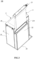
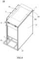
- FIGs. 1 and 2 show schematic structural diagrams of an immersed liquid cooling apparatus 100 according to an example of the disclosure, where a top cover 24 is in a closed state in FIG. 1 and a top cover 24 is in an opened state in FIG. 2 .
- FIG. 3 shows a schematic structural diagram of the immersed liquid cooling apparatus 100 shown in FIG. 1 , where a heat exchange module 3 is in a pulled-out state.
- FIG. 4 shows a schematic structural diagram of the immersed liquid cooling apparatus 100 shown in FIG. 1 viewed from another angle of view.
- Reference numeral X in FIG. 1 indicates a length direction of the immersed liquid cooling apparatus 100.
- Reference numeral Y indicates a width direction of the immersed liquid cooling apparatus 100.
- Reference numeral Z indicates a height direction of the immersed liquid cooling apparatus 100.
- the immersed liquid cooling apparatus 100 described herein includes a cabinet 2 and a heat exchange module 3 in general.
- the cabinet 2 includes an outer frame 23, a cooling groove 21, a mounting groove 22 integrated on an outer wall 211 of the cooling groove 21, and a top cover 24.
- the cooling groove 21 is configured to accommodate an electronic device 4 to be cooled and a first cooling liquid 5 (see FIGs. 5 and 6 ).
- the mounting groove 22 is configured to accommodate the heat exchange module 3 and the first cooling liquid 5 (see FIG. 6 ).
- the cooling groove 21 is in fluid communication with the mounting groove 22 through a through hole 6 (see FIG. 7 ).
- the heat exchange module 3 is suitable for being inserted into the mounting groove 22.
- the outer frame 23 surrounds the cooling groove 21 and the mounting groove 22 in general so as to provide mechanical support for the cooling groove 21 and the mounting groove 22 to some extent.
- the cooling groove 21 and the mounting groove 22 may be mounted on the outer frame 23 through welding or other methods.
- the outer frame 23 may be formed by welding profile square bars.
- the outer frame 23 may also be formed through other processes or by using other materials, which is not strictly limited in an example of the disclosure.
- the cooling groove 21 and the mounting groove 22 may be formed by welding stainless steel plates. In other examples, the cooling groove 21 and the mounting groove 22 may be formed through other processes or by using other materials, which is not strictly limited in an example of the disclosure.
- the top cover 24 is rotatably connected to the outer frame 23 and is switchable between a closed state in which the cooling groove 21 is closed and an opened state in which the cooling groove 21 is opened.
- FIG. 1 shows that the top cover 24 is in the closed state
- FIG. 2 shows that the top cover 24 is in the opened state.
- the top cover 24 in the closed state can reduce leakage of the first cooling liquid 5 in the cooling groove 21 and prevent external contaminants from entering the cooling groove 21.
- an operator can mount or maintain the electronic device 4 in the cooling groove 21 and inject the first cooling liquid 5 into the cooling groove 21.
- the first cooling liquid 5 includes a fluorinated liquid or mineral oil. In other examples, the first cooling liquid 5 may also be in other types, which is not strictly limited in an example of the disclosure.
- the top cover 24 may be opened relative to the outer frame 23 by 90 degrees or above. At a maximum opening angle, a stopping member (not shown) may be provided to limit a position of the top cover 24.
- the top cover 24 may be connected to a side of the outer frame 23 by means of a hinge. In other examples, the top cover 24 may be connected to the outer frame 23 through other methods, such as through matching of a shaft hole, which is not strictly limited in an example of the disclosure.
- the top cover 24 includes a frame 241 and a transparent portion 242 surrounded by the frame 241.
- the frame 241 is connected to the outer frame 23 and may rotate relative to the outer frame 23.
- the frame 241 may be made of aluminum alloy or other types of metallic or non-metallic materials.
- the transparent portion 242 may be made of a transparent polycarbonate (PC) material or other types of transparent materials.
- a first seal ring (not shown) is provided on a side of the top cover 24 facing the cooling groove 21. When the top cover 24 is in the closed state, the top cover 24 is sealed off from the cooling groove 21 by the first seal ring.
- the first seal ring may be made of ethylene propylene diene monomer (EPDM) rubber or other types of seal materials. Performance of seal between the top cover 24 and the cooling groove 21 can be improved by using the first seal ring such that leakage of the first cooling liquid 5 in the cooling groove 24 can be further reduced.
- the cabinet 2 in order to open or close the top cover 24, the cabinet 2 further includes a hydraulic driving apparatus (not shown).
- the hydraulic driving apparatus is connected between the outer frame 23 and the top cover 24 to be used for driving the top cover 24 to be switched between the closed state and the opened state.
- the top cover 24 can be conveniently opened or closed by means of the hydraulic driving apparatus.
- the hydraulic driving apparatus includes a pair of hydraulic rods (not shown).
- One of the pair of hydraulic rods is connected between a first side 243 of the top cover 24 and a corresponding side of the outer frame 23.
- the other one of the pair of hydraulic rods is connected between a second side 244 of the top cover 24 and a corresponding side of the outer frame 23.
- the first side 243 and the second side 244 of the top cover 24 are opposite sides. The states of the top cover 24 can be rapidly and reliably switched by means of the pair of hydraulic rods oppositely provided.
- top cover 24 may be switched between the closed state and the opened state through other methods, which is not strictly limited in an example of the disclosure.
- a handle (not shown) may also be provided on a side of the top cover 24 facing away from the cooling groove 21. By means of such an arrangement, the operator can open and close the top cover 24 by gripping the handle.
- the heat exchange module 3 is suitable for being inserted into the mounting groove 22 or pulled out from the mounting groove 22, the operator can conveniently use different heat exchange modules 3 according to different cooling requirements of the electronic device 4.
- both the cooling groove 21 and the mounting groove 22 are used to accommodating the first cooling liquid 5.
- the first cooling liquid 5 may be used to immerse the electronic device 4 for cooling the electronic device 4.
- the heat exchange module 3 may be at least partially immersed in the first cooling liquid 5.
- the heat exchange module 3 may be connected to an external cooling device (such as a cooling tower) so as to receive a second cooling liquid provided by the external cooling device.
- a temperature of the second cooling liquid in the heat exchange module 3 is less than a temperature of the first cooling liquid 5 in the mounting groove 22 such that the first cooling liquid 5 in the mounting groove 22 can be cooled.
- the second cooling liquid in the heat exchange module 3 may include deionized water.
- the second cooling liquid may also be in other types, which is not strictly limited in an example of the disclosure.
- the heat exchange module 3 includes a cooling liquid circulation pipeline 31, a heat exchanger 32 and a cooling liquid driving apparatus 33.
- the cooling liquid circulation pipeline 31 is in fluid communication with the heat exchanger 32 for enabling the second cooling liquid to be circulated between the heat exchanger 32 and the external cooling device (such as a cooling tower).
- the external cooling device such as a cooling tower.
- a second cooling liquid having a low temperature can be provided for the heat exchanger 32.
- the heat exchanger 32 is configured to cool the first cooling liquid 5 outside the heat exchanger by means of the second cooling liquid inside the heat exchanger.
- the cooling liquid driving apparatus 33 is used for circulating the first cooling liquid 5 between the mounting groove 22 and the cooling groove 21.
- the first cooling liquid 5 having a low temperature entering the cooling groove 21 from the mounting groove 22 can absorb heat from the electronic device 4.
- the first cooling liquid 5 heated through heat absorption can enter the mounting groove 22 from the cooling groove 21 through the through hole 6 and be cooled again by the heat exchanger 32 in the mounting groove 22 to perform next circulation.
- the heat exchanger 32 and the cooling liquid driving apparatus 33 may be immersed in the first cooling liquid 5. Since the second cooling liquid received by means of the cooling liquid circulation pipeline 31 exits in the heat exchanger 32, a temperature of the first cooling liquid 5 in the mounting groove 22 can be reduced by the second cooling liquid.
- the cooling liquid circulation pipeline 31 may include two groups of liquid intake and return pipelines. Through such a redundant design, when one set of liquid intake and return pipelines do not operate, the other set of liquid intake and return pipelines can still normally operate, thereby improving reliability of the system.
- the heat exchanger 32 may include a plate heat exchanger. In other examples, the heat exchanger 32 may include other types of heat exchangers, which is not strictly limited in an example of the disclosure.
- dense micro-cavity structures may be provided in the heat exchanger 32, such that a contact area between the second cooling liquid and the heat exchanger 32 and heat exchange efficiency of the heat exchanger 32 are increased.
- the heat exchanger 32 may be made of a stainless steel material. In other examples, the heat exchanger 32 may be made of other types of materials having high thermal conductivity, which is not strictly limited in an example of the disclosure.
- FIG. 7 shows an exemplary arrangement of the through hole 6 on the outer wall 211 of the cooling groove 21.
- the through hole 6 include a first set of through holes 61 and a second set of through holes 62.
- the cooling liquid driving apparatus 33 will be close to the first set of through holes 61 for driving the first cooling liquid 5 in the mounting groove 22 into the cooling groove 21 through the first set of through holes 61, and enabling the first cooling liquid 5 in the cooling groove 21 to flow into the mounting groove 22 by means of the second set of through holes 62.
- each through hole of the first set of through holes 61 may be in an elliptical shape. It should be understood that in other examples, each through hole of the first set of through holes 61 may be in other shapes, such as a circular shape, a rectangular shape, a square shape and a strip shape, which is not strictly limited in an example of the disclosure.
- each through hole of the second set of through holes 62 may be in an elliptical shape.
- each through hole of the second set of through holes 62 may be in other shapes, such as a circular shape, a rectangular shape, a square shape and a strip shape, which is not strictly limited in an example of the disclosure.
- the first set of through holes 61 are close to a bottom side of the mounting groove 22 and the second set of through holes 62 are close to a top side of the mounting groove 22.
- the cooling liquid driving apparatus 33 moves close to the bottom side of the mounting groove 22, and the heat exchanger 32 is located above the cooling liquid driving apparatus 33 and adjacent to the cooling liquid driving apparatus 33.
- the first cooling liquid 5 cooled by the heat exchanger 32 can be timely transported to the cooling groove 21 by arranging the cooling liquid driving apparatus 33 adjacent to the heat exchanger 32, such that the cooling performance of the liquid cooling apparatus 100 is further improved.
- the cooling liquid driving apparatus 33 includes a plurality of circulation pumps.
- each circulation pump will be close to a corresponding through hole of the first set of through holes 61.
- the plurality of circulation pumps can drive the first cooling liquid 5 into the corresponding through holes such that a speed of the first cooling liquid 5 circulating between the mounting groove 22 and the cooling groove 21 can be further increased.
- an additional circulation pump may be provided adjacent to each through hole of the first set of through holes 61.
- cooling liquid driving apparatus 33 may also include other types of driving units or use other arrangements, which is not strictly limited in an example of the disclosure.
- the heat exchange module 3 further includes a plurality of cooling liquid replacement blocks 34.
- the plurality of cooling liquid replacement blocks 34 may be at least partially immersed in the first cooling liquid 5 in the mounting groove 22.
- the cooling liquid replacement blocks 34 can reduce a volume of the first cooling liquid 5 in the mounting groove 22 such that a liquid level of the first cooling liquid 5 in the mounting groove 22 can be risen, a usage amount of the first cooling liquid 5 required in the cabinet 2 and overall cost are reduced.
- the plurality of cooling liquid replacement blocks 34 are close to the top side of the mounting groove 22.
- the cooling liquid replacement blocks 34 may also be provided at other positions, which is not strictly limited in an example of the disclosure.
- channels 35 for the first cooling liquid 5 to flow through are provided between adjacent cooling liquid replacement blocks 34 of the plurality of cooling liquid replacement blocks 34.
- the first cooling liquid 5 may flow through the channels 35 between the cooling liquid replacement blocks 34, such that a stable fluid path is formed.
- the heat exchange module 3 includes a support portion 36 located at a top.
- the support portion 36 is located outside the mounting groove 22 and supported by the outer frame 23. In this way, overall weight of the heat exchange module 3 can be reliably supported on the outer frame 23.
- a second seal ring (not shown) is provided on a side of the support portion 36 facing the mounting groove 22.
- the support portion 36 is sealed off from the mounting groove 22 by the second seal ring.
- Performance of seal between the support portion 36 and the mounting groove 22 can be improved by using the second seal ring, such that leakage of the first cooling liquid 5 in the mounting groove 22 is further reduced.
- a pair of handles 37 are provided on the support portion 36. By gripping the handles 37, an operator can conveniently operate the heat exchange module 3, for instance, pull out the heat exchange module 3 from the mounting groove 22 or insert the heat exchange module 3 into the mounting groove 22.
- the immersed liquid cooling apparatus 100 further includes a height-adaptive support 7.
- the height-adaptive support 7 is provided under the cooling groove 21 and supports the cooling groove 21. Through such an arrangement, a user can match, according to actual depth requirements of the electronic device 4, liquid cooling devices having different height-adaptive supports 7 such that a usage amount of the first cooling liquid 5 can be greatly reduced, and carbon neutralization can be boosted. In some cases, the height-adaptive support 7 may also support the mounting groove 22.
- FIG. 9 shows a schematic flow path of a first cooling liquid 5, which is indicated by an arrow.
- the heat exchanger 32 and the cooling liquid driving apparatus 33 may be immersed in the first cooling liquid 5. Since the second cooling liquid received by means of the cooling liquid circulation pipeline 31 exits in the heat exchanger 32, a temperature of the first cooling liquid 5 in the mounting groove 22 can be reduced by the second cooling liquid.
- the cooling liquid driving apparatus 33 then drives the first cooling liquid 5 in the mounting groove 22 into the cooling groove 21 through the first set of through holes 61.
- the first cooling liquid flows through the electronic device 4 from bottom to top to cool the electronic device.
- the first cooling liquid 5 in the cooling groove 21 after absorbing heat from the electronic device 4 flows into the mounting groove 22 through the second set of through holes 62.
- the first cooling liquid 5 advances from top to bottom again in the mounting groove 22 and is cooled by the heat exchanger 32 to perform next circulation.
- the second cooling liquid in the heat exchanger 32 may flow in a left-right direction, while the first cooling liquid 5 in the mounting groove 22 may flow up and down in a vertical direction, such that heat exchange in a form of cross flow is formed, and heat exchange efficiency of the heat exchanger 32 is enhanced.
- the electronic device 4 includes a server or a switch. In other examples, the electronic device 4 may also be in other types, which is not strictly limited in an example of the disclosure.
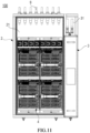
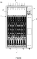
- FIGs. 10-12 show different arrangements of an electronic device 4 of an immersed liquid cooling apparatus 100 according to an example of the disclosure.
- the electronic device 4 includes both a computation server and a storage server.
- the electronic device 4 mainly includes a storage server.
- the electronic device 4 mainly includes a computation server.
- a size of the cabinet 2 of the immersed liquid cooling apparatus 100 shown in FIGs. 10-12 may be, for instance, 8 U. In other examples, the size of the cabinet 2 may be greater than or less than 8 U, which is not strictly limited in an example of the disclosure.
- a length in length direction X of the cabinet 2 is only about one sixth of that of the conventional cabinet.
- the conventional cabinet has a length generally about 3 m, while the cabinet 2 in an example of the disclosure has a length of only 500 mm. The size is significantly reduced.
- the length of the cabinet 2 in length direction X may be adjusted according to a number of electronic devices 4 provided in the cabinet. It is recommended to keep the length ranging from 500 mm to 800 mm.
- FIGs. 10-12 further show an electrically-conductive terminal 8, which is configured to be connected to the electronic device 4 to perform power supply and signal/data transmission to the electronic device 4.
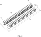
- FIG. 13 shows a schematic structural diagram of a liquid cooling system 900 according to an example of the disclosure.
- the liquid cooling system 900 includes a plurality of immersed liquid cooling apparatuses 100 provided side by side.
- Each immersed liquid cooling apparatus 100 of the plurality of immersed liquid cooling apparatuses 100 may be any of the immersed liquid cooling apparatuses 100 described in combination with FIGs. 1-12 .
- immersed liquid cooling apparatuses are deployed in a small, medium or large data center, users can set a number of the immersed liquid cooling apparatuses 100 according to service requirements, such that service systems of different scales are formed, and a more flexible and efficient immersed liquid cooling system deployment mode is brought to the data center. Moreover, the problem of excessive loss of single failure caused by a large number of information technology (IT) devices in a single cabinet is solved. For instance, in some usage scenarios of edge computation, such small immersed liquid cooling apparatuses 100 may be sparely and independently deployed, which brings more application scenarios of miniaturized flexible deployment.
- IT information technology
- the immersed liquid cooling apparatus 100 may be provided in a computer room of a data center in advance by pre-positioning the cabinet 2 and the heat exchange module 3 in the data center, and the cooling liquid circulation pipeline 31 is connected to a primary side cooling liquid providing system (such as a cooling tower) for debugging. Subsequently, when there is a service requirement, the user can purchase an IT device, deploy the IT device into the cooling groove 21 of the cabinet 2, and finally add the first cooling liquid 5 to the cooling groove, such that the entire system is deployed. In this way, deployment time of the data center can be greatly reduced.
- a primary side cooling liquid providing system such as a cooling tower
- An example of the disclosure further provides a data center deployed in a large-scale cluster manner.
- the data center includes a plurality of immersed liquid cooling apparatuses 100, which are pre-provided in a computer room of a data center, where each immersed liquid cooling apparatus 100 is internally provided with no electronic device 4 and filled with no first cooling liquid 5; and a primary side cooling liquid providing system (such as a cooling tower), which is connected to the cooling liquid circulation pipeline 31 in the heat exchange module 3 of each immersed liquid cooling apparatus 100 by means of a liquid transportation pipeline.
- a primary side cooling liquid providing system such as a cooling tower
- the computation server generally has a depth of 600 mm
- the storage server has a depth of 800 mm.
- the cabinet 2 can adjust the depth of the cooling groove 21 by means of the height-adaptive support 7 at a bottom. By designing the cooling grooves 21 having different depths, an amount of a cooling liquid used by the IT device in the liquid cooling system 900 can be reduced by about 5% - 33%.
- An example of the disclosure provides a design of a liquid cooling system with a heat exchanger integrated therein. Self-circulating cooling of IT devices such as servers and switches provided in the liquid cooling system is efficiently implemented. Data center investment and overall operating cost are reduced. Overall power utilization efficiency (PUE) of the data center is controlled below 1.1. Carbon neutralization is boosted.
- PUE power utilization efficiency
Landscapes
- Engineering & Computer Science (AREA)
- Microelectronics & Electronic Packaging (AREA)
- Physics & Mathematics (AREA)
- Thermal Sciences (AREA)
- Computer Hardware Design (AREA)
- General Engineering & Computer Science (AREA)
- Aviation & Aerospace Engineering (AREA)
- Cooling Or The Like Of Electrical Apparatus (AREA)
Abstract
Description
- The disclosure claims the benefit of priority to
Chinese Patent Application No. 202111582976.0, filed with the Chinese Patent Office on December 22, 2021 - Examples of the disclosure generally relate to the technical field of cooling of electronic devices, and particularly relate to an immersed liquid cooling apparatus and a liquid cooling system including the immersed liquid cooling apparatus.
- As a new generation of information communication technologies such as 5G, cloud computation, big data and artificial intelligence and the real economy have been integrated and developed, data centers have been oriented towards the whole society from some companies, and become a novel type of infrastructures.
- The novel infrastructures put forward higher requirements on cooling solutions and overall energy efficiency of a cooling center. Data is growing faster than imagined with the advent of the period of big data. In order to process, store and transmit massive data, power consumption of an information technology (IT) device is increased exponentially, which presents a huge challenge of cooling chips. Traditional cooling solutions cannot satisfy requirements of efficient cooling of an electronic information device any more. Moreover, national, local and industrial energy policies have been successively issued, which put forward higher requirements for energy-saving indexes of the data centers.
- Room-level air conditioners and underfloor air supply cooling methods are generally adopted in traditional computer rooms of the data centers. The method, low in construction cost and high in utilization rate of computer rooms, is used for cooling 3 kW - 5 kW single cabinets. However, since a large number of rack and blade servers have been used in the computer rooms, the number of devices in the single cabinets, power density and heating density have been significantly increased. Traditional computer-room-level air conditioners are unable to solve the cooling problem of the IT devices. Accordingly, in-row air conditioners and backplane air conditioners emerged. Terminals of such novel air conditioners are closer to heat sources, so the problems of local hot spots and high heating density can be solved. Power consumption of draught fans is reduced through short-distance cold transmission, thereby saving energy. All of the room-level air conditioners, the in-row air conditioners and the backplane air conditioners perform cooling through heat exchange between cold air and central processing units (CPUs) of servers after cooling the air. Due to low heat exchange efficiency and heat flux density of air, air-cooled servers have problems of high cooling energy consumption, loud noise, low device density, etc.
- In order to solve the cooling problem of an IT device having ultra-high power density, the data centers began to adopt a liquid cooling technology. A working fluid is used as an intermediate heat transfer medium to transfer heat from a heating area to a distant place for cooling. Cooling efficiency of the liquid cooling technology is significantly greater than that of air cooling. Therefore, the cooling problem of a high-density server can be effectively solved, energy consumption of cooling systems can be reduced, and noise can be lowered.
- In existing data centers adopting liquid cooling solutions, a conventional immersed liquid cooling system is generally a large-sized cabinet (generally having a length about 3 m) equipped with one or more cooling liquid distribution units (CDUs). The cooling liquid distribution units are provided on left and right sides of the cabinet. The inventor of the disclosure discovers that such a conventional immersed liquid cooling system has plenty of problems.
- Firstly, the cabinet of the conventional immersed liquid cooling system is difficult to operate and maintain due to the large size. Since an operator can only stand in front of the cabinet instead of standing on the left or right side of the cabinet for maintenance, operation is difficult. For instance, in the current immersed liquid cooling industry, systems applied to immersion cooling of servers basically utilize horizontal cabinets having a length about 2 m - 3 m, leading to difficulties in implementation, operation and maintenance.
- Secondly, since the conventional immersed liquid cooling system is equipped with one or more sets of cooling liquid distribution units, the system becomes complex in overall structure.
- Thirdly, the conventional immersed liquid cooling system is poorly adapted to the IT device. In the conventional immersed liquid cooling system, it is required to use cabinets having the same height to assemble IT devices having different heights. If the height of the IT device to be assembled is less than the height of the cabinet, the server is required to share more cooling liquids, which results in higher cost.
- Fourthly, the IT device on which the conventional immersed liquid cooling system is carried is required to have a large capacity. Therefore, device and liquid waste will be caused for some small-scale IT systems.
- Therefore, there is a need of improved liquid cooling solutions to data centers.
- An objective of the disclosure is to provide an immersed liquid cooling apparatus and a liquid cooling system including the immersed liquid cooling apparatus, so as to at least partially solve the above problems in the prior art.
- According to a first aspect of the disclosure, an immersed liquid cooling apparatus is provided. The immersed liquid cooling apparatus includes a cabinet, where the cabinet includes a cooling groove and a mounting groove integrated on an outer wall of the cooling groove, the cooling groove is used for accommodating an electronic device to be cooled and a first cooling liquid, the mounting groove is used for accommodating the first cooling liquid, and the cooling groove is in fluid communication with the mounting groove by means of a through hole; and a heat exchange module suitable for being inserted into the mounting groove, where the heat exchange module includes a cooling liquid circulation pipeline, a heat exchanger and a cooling liquid driving apparatus, the cooling liquid circulation pipeline is in fluid communication with the heat exchanger to be used for providing a second cooling liquid for the heat exchanger, the heat exchanger is used for using the second cooling liquid inside the heat exchanger to cool the first cooling liquid outside the heat exchanger, and the cooling liquid driving apparatus is used for enabling the first cooling liquid to be circulated between the mounting groove and the cooling groove.
- The cabinet in the immersed liquid cooling apparatus according to an example of the disclosure is small in size and light in overall weight, such that the problem of difficult deployment is solved. An operator can perform maintenance on all sides of the liquid cooling apparatus such that components of an internal electronic device can be extremely easily maintained. In addition, since the cabinet and the heat exchange module are integrated together, the entire system is not required to be equipped with an additional cooling liquid distribution unit for usage and therefore is extremely flexible and convenient.
- In some examples, the through hole includes a first set of through holes and a second set of through holes. In a case that the heat exchange module is inserted into the mounting groove, the cooling liquid driving apparatus is provided to be close to the first set of through holes to be used for driving the first cooling liquid in the mounting groove into the cooling groove and enabling the first cooling liquid in the cooling groove to flow into the mounting groove by means of the second set of through holes. In such examples, the first cooling liquid can rapidly circulate between the mounting groove and the cooling groove by arranging the cooling liquid driving apparatus adjacent to the first set of through holes.
- In some examples, the first set of through holes are provided to be close to a bottom side of the mounting groove, and the second set of through holes are provided to be close to a top side of the mounting groove. In such examples, most of the first cooling liquid in the mounting groove can circularly flow into the cooling groove, such that cooling performance of the liquid cooling apparatus is improved.
- In some examples, in the case that the heat exchange module is inserted into the mounting groove, the cooling liquid driving apparatus is provided to be close to the bottom side of the mounting groove, and the heat exchanger is located above the cooling liquid driving apparatus and adjacent to the cooling liquid driving apparatus. In such examples, the first cooling liquid cooled by the heat exchanger can be timely transported to the cooling groove by arranging the cooling liquid driving apparatus adjacent to the heat exchanger, such that the cooling performance of the liquid cooling apparatus is further improved.
- In some examples, the cooling liquid driving apparatus includes a plurality of circulation pumps. In the case that the heat exchange module is inserted into the mounting groove, each of the plurality of circulation pumps is provided to be close to a corresponding through hole of the first set of through holes. In such examples, the plurality of circulation pumps drive the first cooling liquid into the corresponding through holes such that a speed of the first cooling liquid circulating between the mounting groove and the cooling groove can be further increased.
- In some examples, the cabinet further includes an outer frame and a top cover. The outer frame surrounds the cooling groove and the mounting groove. The top cover is rotatably connected to the outer frame and is switchable between a closed state in which the cooling groove is closed and an opened state in which the cooling groove is opened. In such examples, by closing the first cooling groove with the top cover, leakage of the first cooling liquid in the cooling groove can be reduced and external contaminants can be prevented from entering the cooling groove.
- In some examples, the top cover includes a frame and a transparent portion surrounded by the frame. In such examples, the electronic device in the cooling groove can be observed through the transparent portion such that operating states of the components of the electronic device can be timely known.
- In some examples, a first seal ring is provided on a side of the top cover facing the cooling groove. In a case that the top cover is in the closed state, the top cover is sealed off from the cooling groove by the first seal ring. In such examples, performance of seal between the top cover and the cooling groove can be improved by using the first seal ring such that leakage of the first cooling liquid in the cooling groove can be further reduced.
- In some examples, the cabinet further includes a hydraulic driving apparatus. The hydraulic driving apparatus is connected between the outer frame and the top cover for driving the top cover to be switched between the closed state and the opened state. In such examples, the top cover can be conveniently opened or closed by using the hydraulic driving apparatus.
- In some examples, the hydraulic driving apparatus includes a pair of hydraulic rods. One of the pair of hydraulic rods is connected between a first side of the top cover and the outer frame. The other one of the pair of hydraulic rods is connected between a second side of the top cover and the outer frame. The first side and the second side of the top cover are opposite sides. In such examples, the states of the top cover can be rapidly and reliably switched by means of the pair of hydraulic rods oppositely provided.
- In some examples, the immersed liquid cooling apparatus further includes a height-adaptive support. The height-adaptive support is provided under the cooling groove to support the cooling groove. In such examples, a user can match, according to actual depth requirements of the electronic device, liquid cooling devices having different height-adaptive supports such that a usage amount of the first cooling liquid can be greatly reduced, and carbon neutralization can be boosted.
- In some examples, the heat exchange module further includes a plurality of cooling liquid replacement blocks. In the case that the heat exchange module is inserted into the mounting groove, the plurality of cooling liquid replacement blocks may be at least partially immersed into the first cooling liquid in the mounting groove. In such examples, when the heat exchange module is inserted into the mounting groove, the cooling liquid replacement blocks can reduce a volume of the first cooling liquid such that a usage amount of the first cooling liquid required in the cabinet and overall cost can be reduced.
- In some examples, in the case that the heat exchange module is inserted into the mounting groove, the plurality of cooling liquid replacement blocks are close to a top side of the mounting groove.
- In some examples, channels for the first cooling liquid to flow through are provided between adjacent cooling liquid replacement blocks of the plurality of cooling liquid replacement blocks. In such examples, the first cooling liquid can flow through the channels between the cooling liquid replacement blocks, such that a stable fluid path is formed.
- In some examples, the heat exchange module further includes a support portion. When the heat exchange module is inserted into the mounting groove, the support portion is located outside the mounting groove. In such examples, the cabinet can reliably support the heat exchange module by means of the support portion. The support portion can prevent leakage of the first cooling liquid in the mounting groove.
- In some examples, a second seal ring is provided on a side of the support portion facing the mounting groove. When the heat exchange module is inserted into the mounting groove, the support portion is sealed off from the mounting groove by the second seal ring. In such examples, performance of seal between the support portion and the mounting groove can be improved by using the second seal ring, such that leakage of the first cooling liquid in the mounting groove is further reduced.
- In some examples, the cabinet has a height ranging from 1000 mm to 1100 mm, a width ranging from 750 mm to 850 mm and a length ranging from 500 mm to 800 mm. In such examples, if a cabinet having the substantially same height and width as a conventional cabinet, a length of the cabinet is significantly reduced compared with a length of the conventional cabinet, and therefore a volume of the cabinet is also significantly reduced.
- In some examples, the first cooling liquid includes a fluorinated liquid or mineral oil, and/or the second cooling liquid includes deionized water.
- In some examples, the electronic device includes a server or a switch.
- According to a second aspect of the disclosure, a liquid cooling system is provided. The liquid cooling system includes a plurality of immersed liquid cooling apparatuses provided side by side. Each immersed liquid cooling apparatus of the plurality of immersed liquid cooling apparatuses is the immersed liquid cooling apparatus according to the first aspect of the disclosure.
- These contents are provided to introduce selection of concepts in a simplified manner, and will be further described below in the detailed description of embodiments. These contents are neither intended to identify key features or essential features of contents of the disclosure, nor intended to limit the scope of the contents of the disclosure.
- The above and other objectives, features and advantages of examples of the disclosure will be easy to understand by reading the following detailed descriptions with reference to accompanying drawings. In the accompanying drawings, several examples of the disclosure are shown by way of instances in a non-limitative way.
-
FIGs. 1 and2 show schematic structural diagrams of an immersed liquid cooling apparatus according to an example of the disclosure, where a top cover is in a closed state inFIG. 1 and a top cover is in an opened state inFIG. 2 ; -
FIG. 3 shows a schematic structural diagram of the immersed liquid cooling apparatus shown inFIG. 1 , where a heat exchange module is in a pulled-out state; -
FIG. 4 shows a schematic structural diagram of the immersed liquid cooling apparatus shown inFIG. 1 viewed from another angle of view; -
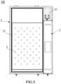
FIG. 5 shows a top view of the immersed liquid cooling apparatus shown inFIG. 2 , where the top cover is not shown, such that a first cooling liquid in a cooling groove is shown; -
FIG. 6 shows a top view of the immersed liquid cooling apparatus shown inFIG. 2 , where the top cover and a heat exchange module are not shown, such that a first cooling liquid in a cooling groove and a mounting groove is shown; -
FIG. 7 shows a schematic structural diagram of an outer wall of a cooling groove on which a mounting groove is integrated according to an example of the disclosure; -
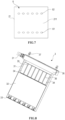
FIG. 8 shows a schematic structural diagram of a heat exchange module according to an example of the disclosure; -
FIG. 9 shows a schematic flow path of a first cooling liquid; -
FIGs. 10-12 show different arrangements of an electronic device of an immersed liquid cooling apparatus according to an example of the disclosure; and -
FIG. 13 shows a schematic structural diagram of a liquid cooling system according to an example of the disclosure. - Preferred examples of the disclosure will be described in more detail below with reference to accompanying drawings. Although the preferred examples of the disclosure are shown in the accompanying drawings, it should be understood that the disclosure can be implemented in various forms and should not be limited by the examples set forth herein. On the contrary, these examples are provided to make the disclosure more thorough and complete, and to fully convey the scope of the disclosure to those skilled in the art.
- The terms "comprise", "include" and their variations used herein represent open inclusion, that is, "comprise but not limited to" and "include but not limited to". The term "or" represents "and/or" unless specifically stated. The term "on the basis of' represents "at least partially on the basis of'. The terms "an exemplary example" and "an example" represent "at least one exemplary example". The term "another example" represents "at least one another example". The terms "first", "second" etc. can refer to different objects or the same object.
- As described above, the conventional immersed liquid cooling system has various problems, such as difficult operation and maintenance, complex overall architecture, poor adaptability, and waste of cooling liquids. Examples of the disclosure provide an immersed liquid cooling apparatus with a heat exchanger integrated therein and a liquid cooling system including the immersed liquid cooling apparatus, so as to reduce operation and maintenance difficulty levels, reduce architecture complexity, enhance adaptability and conserve cooling liquids. Principles of the disclosure will be described hereinafter in combination with
FIGs. 1-13 . -
FIGs. 1 and2 show schematic structural diagrams of an immersedliquid cooling apparatus 100 according to an example of the disclosure, where atop cover 24 is in a closed state inFIG. 1 and atop cover 24 is in an opened state inFIG. 2 .FIG. 3 shows a schematic structural diagram of the immersedliquid cooling apparatus 100 shown inFIG. 1 , where aheat exchange module 3 is in a pulled-out state.FIG. 4 shows a schematic structural diagram of the immersedliquid cooling apparatus 100 shown inFIG. 1 viewed from another angle of view. Reference numeral X inFIG. 1 indicates a length direction of the immersedliquid cooling apparatus 100. Reference numeral Y indicates a width direction of the immersedliquid cooling apparatus 100. Reference numeral Z indicates a height direction of the immersedliquid cooling apparatus 100. - As shown in
FIGs. 1-4 , the immersedliquid cooling apparatus 100 described herein includes acabinet 2 and aheat exchange module 3 in general. Thecabinet 2 includes anouter frame 23, a coolinggroove 21, a mountinggroove 22 integrated on anouter wall 211 of the coolinggroove 21, and atop cover 24. The coolinggroove 21 is configured to accommodate anelectronic device 4 to be cooled and a first cooling liquid 5 (seeFIGs. 5 and6 ). The mountinggroove 22 is configured to accommodate theheat exchange module 3 and the first cooling liquid 5 (seeFIG. 6 ). The coolinggroove 21 is in fluid communication with the mountinggroove 22 through a through hole 6 (seeFIG. 7 ). Theheat exchange module 3 is suitable for being inserted into the mountinggroove 22. - As shown in
FIGs. 1-4 , theouter frame 23 surrounds the coolinggroove 21 and the mountinggroove 22 in general so as to provide mechanical support for the coolinggroove 21 and the mountinggroove 22 to some extent. The coolinggroove 21 and the mountinggroove 22 may be mounted on theouter frame 23 through welding or other methods. In some examples, theouter frame 23 may be formed by welding profile square bars. In other examples, theouter frame 23 may also be formed through other processes or by using other materials, which is not strictly limited in an example of the disclosure. - In some examples, the cooling
groove 21 and the mountinggroove 22 may be formed by welding stainless steel plates. In other examples, the coolinggroove 21 and the mountinggroove 22 may be formed through other processes or by using other materials, which is not strictly limited in an example of the disclosure. - As shown in
FIGs. 1 and2 , thetop cover 24 is rotatably connected to theouter frame 23 and is switchable between a closed state in which the coolinggroove 21 is closed and an opened state in which the coolinggroove 21 is opened.FIG. 1 shows that thetop cover 24 is in the closed state, whileFIG. 2 shows that thetop cover 24 is in the opened state. Thetop cover 24 in the closed state can reduce leakage of thefirst cooling liquid 5 in the coolinggroove 21 and prevent external contaminants from entering the coolinggroove 21. When thetop cover 24 in the opened state, an operator can mount or maintain theelectronic device 4 in the coolinggroove 21 and inject thefirst cooling liquid 5 into the coolinggroove 21. - In some examples, the
first cooling liquid 5 includes a fluorinated liquid or mineral oil. In other examples, thefirst cooling liquid 5 may also be in other types, which is not strictly limited in an example of the disclosure. - In some examples, the
top cover 24 may be opened relative to theouter frame 23 by 90 degrees or above. At a maximum opening angle, a stopping member (not shown) may be provided to limit a position of thetop cover 24. - In some examples, the
top cover 24 may be connected to a side of theouter frame 23 by means of a hinge. In other examples, thetop cover 24 may be connected to theouter frame 23 through other methods, such as through matching of a shaft hole, which is not strictly limited in an example of the disclosure. - In some examples, as shown in
FIGs. 1 and2 , thetop cover 24 includes aframe 241 and atransparent portion 242 surrounded by theframe 241. Theframe 241 is connected to theouter frame 23 and may rotate relative to theouter frame 23. Theframe 241 may be made of aluminum alloy or other types of metallic or non-metallic materials. Thetransparent portion 242 may be made of a transparent polycarbonate (PC) material or other types of transparent materials. By arranging thetransparent portion 242, even when thetop cover 24 is in the closed state, the operator can observe theelectronic device 4 in the coolinggroove 21 through thetransparent portion 242, so as to timely know operating states of components of theelectronic device 4. - In some examples, a first seal ring (not shown) is provided on a side of the
top cover 24 facing the coolinggroove 21. When thetop cover 24 is in the closed state, thetop cover 24 is sealed off from the coolinggroove 21 by the first seal ring. The first seal ring may be made of ethylene propylene diene monomer (EPDM) rubber or other types of seal materials. Performance of seal between thetop cover 24 and the coolinggroove 21 can be improved by using the first seal ring such that leakage of thefirst cooling liquid 5 in the coolinggroove 24 can be further reduced. - In some examples, in order to open or close the
top cover 24, thecabinet 2 further includes a hydraulic driving apparatus (not shown). The hydraulic driving apparatus is connected between theouter frame 23 and thetop cover 24 to be used for driving thetop cover 24 to be switched between the closed state and the opened state. Thetop cover 24 can be conveniently opened or closed by means of the hydraulic driving apparatus. - In some examples, the hydraulic driving apparatus includes a pair of hydraulic rods (not shown). One of the pair of hydraulic rods is connected between a
first side 243 of thetop cover 24 and a corresponding side of theouter frame 23. The other one of the pair of hydraulic rods is connected between asecond side 244 of thetop cover 24 and a corresponding side of theouter frame 23. Thefirst side 243 and thesecond side 244 of thetop cover 24 are opposite sides. The states of thetop cover 24 can be rapidly and reliably switched by means of the pair of hydraulic rods oppositely provided. - It should be understood that in other examples, the
top cover 24 may be switched between the closed state and the opened state through other methods, which is not strictly limited in an example of the disclosure. - In some examples, a handle (not shown) may also be provided on a side of the
top cover 24 facing away from the coolinggroove 21. By means of such an arrangement, the operator can open and close thetop cover 24 by gripping the handle. - Further, in an example according to the disclosure, since the
heat exchange module 3 is suitable for being inserted into the mountinggroove 22 or pulled out from the mountinggroove 22, the operator can conveniently use differentheat exchange modules 3 according to different cooling requirements of theelectronic device 4. - As mentioned above, both the cooling
groove 21 and the mountinggroove 22 are used to accommodating thefirst cooling liquid 5. In the coolinggroove 21, thefirst cooling liquid 5 may be used to immerse theelectronic device 4 for cooling theelectronic device 4. In the mountinggroove 22, theheat exchange module 3 may be at least partially immersed in thefirst cooling liquid 5. Theheat exchange module 3 may be connected to an external cooling device (such as a cooling tower) so as to receive a second cooling liquid provided by the external cooling device. A temperature of the second cooling liquid in theheat exchange module 3 is less than a temperature of thefirst cooling liquid 5 in the mountinggroove 22 such that thefirst cooling liquid 5 in the mountinggroove 22 can be cooled. - In some examples, the second cooling liquid in the
heat exchange module 3 may include deionized water. In other examples, the second cooling liquid may also be in other types, which is not strictly limited in an example of the disclosure. - An exemplary structure of the
heat exchange module 3 will be described below in combination withFIG. 8 . As shown inFIG. 8 , theheat exchange module 3 includes a coolingliquid circulation pipeline 31, aheat exchanger 32 and a coolingliquid driving apparatus 33. The coolingliquid circulation pipeline 31 is in fluid communication with theheat exchanger 32 for enabling the second cooling liquid to be circulated between theheat exchanger 32 and the external cooling device (such as a cooling tower). Through such an arrangement, a second cooling liquid having a low temperature can be provided for theheat exchanger 32. Theheat exchanger 32 is configured to cool thefirst cooling liquid 5 outside the heat exchanger by means of the second cooling liquid inside the heat exchanger. The coolingliquid driving apparatus 33 is used for circulating thefirst cooling liquid 5 between the mountinggroove 22 and the coolinggroove 21. In this way, thefirst cooling liquid 5 having a low temperature entering the coolinggroove 21 from the mountinggroove 22 can absorb heat from theelectronic device 4. Thefirst cooling liquid 5 heated through heat absorption can enter the mountinggroove 22 from the coolinggroove 21 through the throughhole 6 and be cooled again by theheat exchanger 32 in the mountinggroove 22 to perform next circulation. - As shown in
FIGs. 1-8 , when theheat exchange module 3 is inserted into the mountinggroove 22, theheat exchanger 32 and the coolingliquid driving apparatus 33 may be immersed in thefirst cooling liquid 5. Since the second cooling liquid received by means of the coolingliquid circulation pipeline 31 exits in theheat exchanger 32, a temperature of thefirst cooling liquid 5 in the mountinggroove 22 can be reduced by the second cooling liquid. - In some examples, the cooling
liquid circulation pipeline 31 may include two groups of liquid intake and return pipelines. Through such a redundant design, when one set of liquid intake and return pipelines do not operate, the other set of liquid intake and return pipelines can still normally operate, thereby improving reliability of the system. - In some examples, the
heat exchanger 32 may include a plate heat exchanger. In other examples, theheat exchanger 32 may include other types of heat exchangers, which is not strictly limited in an example of the disclosure. - In some examples, dense micro-cavity structures may be provided in the
heat exchanger 32, such that a contact area between the second cooling liquid and theheat exchanger 32 and heat exchange efficiency of theheat exchanger 32 are increased. - In some examples, the
heat exchanger 32 may be made of a stainless steel material. In other examples, theheat exchanger 32 may be made of other types of materials having high thermal conductivity, which is not strictly limited in an example of the disclosure. -
FIG. 7 shows an exemplary arrangement of the throughhole 6 on theouter wall 211 of the coolinggroove 21. In some examples, as shown inFIG. 7 , the throughhole 6 include a first set of throughholes 61 and a second set of throughholes 62. As shown inFIGs. 1-4 andFIGs. 7 and 8 , in the case that theheat exchange module 3 is inserted into the mountinggroove 22, the coolingliquid driving apparatus 33 will be close to the first set of throughholes 61 for driving thefirst cooling liquid 5 in the mountinggroove 22 into the coolinggroove 21 through the first set of throughholes 61, and enabling thefirst cooling liquid 5 in the coolinggroove 21 to flow into the mountinggroove 22 by means of the second set of throughholes 62. - In some examples, as shown in
FIG. 7 , each through hole of the first set of throughholes 61 may be in an elliptical shape. It should be understood that in other examples, each through hole of the first set of throughholes 61 may be in other shapes, such as a circular shape, a rectangular shape, a square shape and a strip shape, which is not strictly limited in an example of the disclosure. - Similarly, as shown in
FIG. 7 , each through hole of the second set of throughholes 62 may be in an elliptical shape. In other examples, each through hole of the second set of throughholes 62 may be in other shapes, such as a circular shape, a rectangular shape, a square shape and a strip shape, which is not strictly limited in an example of the disclosure. - In some examples, as shown in
FIG. 7 , the first set of throughholes 61 are close to a bottom side of the mountinggroove 22 and the second set of throughholes 62 are close to a top side of the mountinggroove 22. Through such an arrangement, most of thefirst cooling liquid 5 in the mountinggroove 22 can participate in cooling liquid circulation between the coolinggroove 21 and the mountinggroove 22. - In some examples, as shown in
FIGs. 1-4 and8 , when theheat exchange module 3 is inserted into the mountinggroove 22, the coolingliquid driving apparatus 33 moves close to the bottom side of the mountinggroove 22, and theheat exchanger 32 is located above the coolingliquid driving apparatus 33 and adjacent to the coolingliquid driving apparatus 33. Thefirst cooling liquid 5 cooled by theheat exchanger 32 can be timely transported to the coolinggroove 21 by arranging the coolingliquid driving apparatus 33 adjacent to theheat exchanger 32, such that the cooling performance of theliquid cooling apparatus 100 is further improved. - In some examples, as shown in
FIG. 8 , the coolingliquid driving apparatus 33 includes a plurality of circulation pumps. In the case that theheat exchange module 3 is inserted into the mountinggroove 22, each circulation pump will be close to a corresponding through hole of the first set of throughholes 61. Through such an arrangement, the plurality of circulation pumps can drive thefirst cooling liquid 5 into the corresponding through holes such that a speed of thefirst cooling liquid 5 circulating between the mountinggroove 22 and the coolinggroove 21 can be further increased. - In some examples, an additional circulation pump may be provided adjacent to each through hole of the first set of through
holes 61. Through such a redundant design, stability of thefirst cooling liquid 5 circulating between the mountinggroove 21 and the coolinggroove 22 can be improved. - In other examples, the cooling
liquid driving apparatus 33 may also include other types of driving units or use other arrangements, which is not strictly limited in an example of the disclosure. - In some examples, as shown in
FIG. 8 , theheat exchange module 3 further includes a plurality of cooling liquid replacement blocks 34. In the case that theheat exchange module 3 is inserted into the mountinggroove 22, the plurality of cooling liquid replacement blocks 34 may be at least partially immersed in thefirst cooling liquid 5 in the mountinggroove 22. In this way, the cooling liquid replacement blocks 34 can reduce a volume of thefirst cooling liquid 5 in the mountinggroove 22 such that a liquid level of thefirst cooling liquid 5 in the mountinggroove 22 can be risen, a usage amount of thefirst cooling liquid 5 required in thecabinet 2 and overall cost are reduced. - In some examples, as shown in
FIGs. 1-4 and8 , when theheat exchange module 3 is inserted into the mountinggroove 22, the plurality of cooling liquid replacement blocks 34 are close to the top side of the mountinggroove 22. In other examples, the cooling liquid replacement blocks 34 may also be provided at other positions, which is not strictly limited in an example of the disclosure. - In some examples, as shown in
FIG. 8 ,channels 35 for thefirst cooling liquid 5 to flow through are provided between adjacent cooling liquid replacement blocks 34 of the plurality of cooling liquid replacement blocks 34. Thefirst cooling liquid 5 may flow through thechannels 35 between the cooling liquid replacement blocks 34, such that a stable fluid path is formed. - As shown in
FIGs. 1-4 and8 , in some examples, theheat exchange module 3 includes asupport portion 36 located at a top. When theheat exchange module 3 is inserted into the mountinggroove 22, thesupport portion 36 is located outside the mountinggroove 22 and supported by theouter frame 23. In this way, overall weight of theheat exchange module 3 can be reliably supported on theouter frame 23. - In some examples, a second seal ring (not shown) is provided on a side of the
support portion 36 facing the mountinggroove 22. When theheat exchange module 3 is inserted into the mountinggroove 22, thesupport portion 36 is sealed off from the mountinggroove 22 by the second seal ring. Performance of seal between thesupport portion 36 and the mountinggroove 22 can be improved by using the second seal ring, such that leakage of thefirst cooling liquid 5 in the mountinggroove 22 is further reduced. - As shown in
FIGs. 1-4 and8 , in some examples, a pair ofhandles 37 are provided on thesupport portion 36. By gripping thehandles 37, an operator can conveniently operate theheat exchange module 3, for instance, pull out theheat exchange module 3 from the mountinggroove 22 or insert theheat exchange module 3 into the mountinggroove 22. - Return to
FIGs. 1-4 , in some examples, the immersedliquid cooling apparatus 100 further includes a height-adaptive support 7. The height-adaptive support 7 is provided under the coolinggroove 21 and supports the coolinggroove 21. Through such an arrangement, a user can match, according to actual depth requirements of theelectronic device 4, liquid cooling devices having different height-adaptive supports 7 such that a usage amount of thefirst cooling liquid 5 can be greatly reduced, and carbon neutralization can be boosted. In some cases, the height-adaptive support 7 may also support the mountinggroove 22. -
FIG. 9 shows a schematic flow path of afirst cooling liquid 5, which is indicated by an arrow. As shown inFIG. 9 , when theheat exchange module 3 is inserted into the mountinggroove 22, theheat exchanger 32 and the coolingliquid driving apparatus 33 may be immersed in thefirst cooling liquid 5. Since the second cooling liquid received by means of the coolingliquid circulation pipeline 31 exits in theheat exchanger 32, a temperature of thefirst cooling liquid 5 in the mountinggroove 22 can be reduced by the second cooling liquid. The coolingliquid driving apparatus 33 then drives thefirst cooling liquid 5 in the mountinggroove 22 into the coolinggroove 21 through the first set of throughholes 61. The first cooling liquid flows through theelectronic device 4 from bottom to top to cool the electronic device. Then, thefirst cooling liquid 5 in the coolinggroove 21 after absorbing heat from theelectronic device 4 flows into the mountinggroove 22 through the second set of throughholes 62. Thefirst cooling liquid 5 advances from top to bottom again in the mountinggroove 22 and is cooled by theheat exchanger 32 to perform next circulation. - In some examples, as shown in
FIG. 9 , the second cooling liquid in theheat exchanger 32 may flow in a left-right direction, while thefirst cooling liquid 5 in the mountinggroove 22 may flow up and down in a vertical direction, such that heat exchange in a form of cross flow is formed, and heat exchange efficiency of theheat exchanger 32 is enhanced. - In some examples, the
electronic device 4 includes a server or a switch. In other examples, theelectronic device 4 may also be in other types, which is not strictly limited in an example of the disclosure. -
FIGs. 10-12 show different arrangements of anelectronic device 4 of an immersedliquid cooling apparatus 100 according to an example of the disclosure. As shown inFIG. 10 , theelectronic device 4 includes both a computation server and a storage server. As shown inFIG. 11 , theelectronic device 4 mainly includes a storage server. As shown inFIG. 12 , theelectronic device 4 mainly includes a computation server. In some examples, a size of thecabinet 2 of the immersedliquid cooling apparatus 100 shown inFIGs. 10-12 may be, for instance, 8 U. In other examples, the size of thecabinet 2 may be greater than or less than 8 U, which is not strictly limited in an example of the disclosure. - As shown in
FIG. 1 , in a case that a height in height direction Z and a width in width direction Y of thecabinet 2 according to an example of the disclosure are substantially the same as those of a conventional cabinet, a length in length direction X of thecabinet 2 is only about one sixth of that of the conventional cabinet. For instance, in a case that the cabinet has a height ranging from 1000 mm to 1100 mm (for instance, about 1050 mm) and a width ranging from 750 mm to 850 mm (for instance, about 800 mm), the conventional cabinet has a length generally about 3 m, while thecabinet 2 in an example of the disclosure has a length of only 500 mm. The size is significantly reduced. In an example according to the disclosure, the length of thecabinet 2 in length direction X may be adjusted according to a number ofelectronic devices 4 provided in the cabinet. It is recommended to keep the length ranging from 500 mm to 800 mm. -
FIGs. 10-12 further show an electrically-conductive terminal 8, which is configured to be connected to theelectronic device 4 to perform power supply and signal/data transmission to theelectronic device 4. - As shown in
FIGs. 10-12 , since the size of thecabinet 2 is less than that in a conventional liquid cooling solution, an operator can stand on either side of thecabinet 2 to operate theelectronic device 4 in thecabinet 2. - In an example according to the disclosure, by integrating the
cabinet 2 with theheat exchange module 3 and completing cooling exchange through liquid-liquid heat exchange in the entire system, a new architecture of an immersed liquid cooling data center can be greatly simplified. -
FIG. 13 shows a schematic structural diagram of aliquid cooling system 900 according to an example of the disclosure. As shown inFIG. 13 , theliquid cooling system 900 includes a plurality of immersedliquid cooling apparatuses 100 provided side by side. Each immersedliquid cooling apparatus 100 of the plurality of immersedliquid cooling apparatuses 100 may be any of the immersedliquid cooling apparatuses 100 described in combination withFIGs. 1-12 . - Whether the immersed liquid cooling apparatuses are deployed in a small, medium or large data center, users can set a number of the immersed
liquid cooling apparatuses 100 according to service requirements, such that service systems of different scales are formed, and a more flexible and efficient immersed liquid cooling system deployment mode is brought to the data center. Moreover, the problem of excessive loss of single failure caused by a large number of information technology (IT) devices in a single cabinet is solved. For instance, in some usage scenarios of edge computation, such small immersedliquid cooling apparatuses 100 may be sparely and independently deployed, which brings more application scenarios of miniaturized flexible deployment. - In addition, during large-scale cluster deployment, the immersed
liquid cooling apparatus 100 may be provided in a computer room of a data center in advance by pre-positioning thecabinet 2 and theheat exchange module 3 in the data center, and the coolingliquid circulation pipeline 31 is connected to a primary side cooling liquid providing system (such as a cooling tower) for debugging. Subsequently, when there is a service requirement, the user can purchase an IT device, deploy the IT device into the coolinggroove 21 of thecabinet 2, and finally add thefirst cooling liquid 5 to the cooling groove, such that the entire system is deployed. In this way, deployment time of the data center can be greatly reduced. - An example of the disclosure further provides a data center deployed in a large-scale cluster manner. The data center includes a plurality of immersed
liquid cooling apparatuses 100, which are pre-provided in a computer room of a data center, where each immersedliquid cooling apparatus 100 is internally provided with noelectronic device 4 and filled with nofirst cooling liquid 5; and a primary side cooling liquid providing system (such as a cooling tower), which is connected to the coolingliquid circulation pipeline 31 in theheat exchange module 3 of each immersedliquid cooling apparatus 100 by means of a liquid transportation pipeline. Through such an arrangement, the immersedliquid cooling apparatus 100 can be connected to the primary side cooling liquid providing system for debugging in advance, which is conducive to rapid large-scale cluster deployment. - In an example according to the disclosure, the cooling
groove 21 of thecabinet 2 in the immersedliquid cooling apparatus 100 may be designed to have different sizes, for instance, different depths, to be used for accommodating IT devices having different sizes, such as 4 U and 8 U. U represents a height unit of the IT device, 1 U=1.75 in = 4.445 cm, 4U =7 in = 17.78 cm, and 8U = 14 in = 35.56 cm. Correspondingly, the height-adaptive support 7 may have different sizes such that the same set ofouter frame 23 can be suitable fordifferent cooling grooves 21. In some examples, the height-adaptive support 7 may also be a height-adjustable height-adaptive support. - For instance, the computation server generally has a depth of 600 mm, and the storage server has a depth of 800 mm. The
cabinet 2 can adjust the depth of the coolinggroove 21 by means of the height-adaptive support 7 at a bottom. By designing the coolinggrooves 21 having different depths, an amount of a cooling liquid used by the IT device in theliquid cooling system 900 can be reduced by about 5% - 33%. - An example of the disclosure provides a design of a liquid cooling system with a heat exchanger integrated therein. Self-circulating cooling of IT devices such as servers and switches provided in the liquid cooling system is efficiently implemented. Data center investment and overall operating cost are reduced. Overall power utilization efficiency (PUE) of the data center is controlled below 1.1. Carbon neutralization is boosted.
- Various examples of the disclosure are described above. The above descriptions are exemplary, not exhaustive and not limited to the disclosed various examples. Many modifications and variations will be apparent to those of ordinary skill in the art without departing from the scopes and spirits of the described various examples. The terms used herein are chosen to best explain the principles and practical application of various examples or technical improvement in the market, or enable others of ordinary skill in the art to understand various examples disclosed herein.
Claims (20)
- An immersed liquid cooling apparatus (100), comprising:a cabinet (2), wherein the cabinet (2) comprises a cooling groove (21) and a mounting groove (22) integrated on an outer wall (211) of the cooling groove (21), the cooling groove (21) is used for accommodating an electronic device (4) to be cooled and a first cooling liquid (5), the mounting groove (22) is used for accommodating the first cooling liquid (5), and the cooling groove (21) is in fluid communication with the mounting groove (22) by means of a through hole (6); anda heat exchange module (3) suitable for being inserted into the mounting groove (22), wherein the heat exchange module (3) comprises a cooling liquid circulation pipeline (31), a heat exchanger (32) and a cooling liquid driving apparatus (33), the cooling liquid circulation pipeline (31) is in fluid communication with the heat exchanger (32) to be used for providing a second cooling liquid for the heat exchanger (32), the heat exchanger (32) is used for using the second cooling liquid inside the heat exchanger to cool the first cooling liquid (5) outside the heat exchanger, and the cooling liquid driving apparatus (33) is used for enabling the first cooling liquid (5) to be circulated between the mounting groove (22) and the cooling groove (21).
- The immersed liquid cooling apparatus (100) according to claim 1, wherein the through hole (6) comprises a first set of through holes (61) and a second set of through holes (62), wherein in a case that the heat exchange module (3) is inserted into the mounting groove (22), the cooling liquid driving apparatus (33) is provided to be close to the first set of through holes (61) to be used for driving the first cooling liquid (5) in the mounting groove (22) into the cooling groove (21) and enabling the first cooling liquid (5) in the cooling groove (21) to flow into the mounting groove (22) by means of the second set of through holes (62).
- The immersed liquid cooling apparatus (100) according to claim 2, wherein the first set of through holes (61) are provided to be close to a bottom side of the mounting groove (22), and the second set of through holes (62) are provided to be close to a top side of the mounting groove (22).
- The immersed liquid cooling apparatus (100) according to claim 3, wherein in the case that the heat exchange module (3) is inserted into the mounting groove (22), the cooling liquid driving apparatus (33) moves close to the bottom side of the mounting groove (22), and the heat exchanger (32) is located above the cooling liquid driving apparatus (33) and provided adjacent to the cooling liquid driving apparatus (33).
- The immersed liquid cooling apparatus (100) according to claim 2, wherein the cooling liquid driving apparatus (33) comprises a plurality of circulation pumps, wherein in the case that the heat exchange module (3) is inserted into the mounting groove (22), each of the plurality of circulation pumps moves close to a respective through hole of the first set of through holes (61).
- The immersed liquid cooling apparatus (100) according to claim 1, wherein the cabinet (2) further comprises an outer frame (23) and a top cover (24), the outer frame (23) is provided to surround the cooling groove (21) and the mounting groove (22), and the top cover (24) is rotatably connected to the outer frame (23) and is switchable between a closed state in which the cooling groove (21) is closed and an opened state in which the cooling groove (21) is opened.
- The immersed liquid cooling apparatus (100) according to claim 6, wherein the top cover (24) comprises a frame (241) and a transparent portion (242) surrounded by the frame (241).
- The immersed liquid cooling apparatus (100) according to claim 6, wherein a first seal ring is provided on a side of the top cover (24) facing the cooling groove (21), wherein in a case that the top cover (24) is in the closed state, the top cover (24) is sealed off from the cooling groove (21) by the first seal ring.
- The immersed liquid cooling apparatus (100) according to claim 6, wherein the cabinet (2) further comprises a hydraulic driving apparatus, and the hydraulic driving apparatus is connected between the outer frame (23) and the top cover (24) for driving the top cover (24) to be switched between the closed state and the opened state.
- The immersed liquid cooling apparatus (100) according to claim 9, wherein the hydraulic driving apparatus comprises a pair of hydraulic rods, one of the pair of hydraulic rods is connected between a first side (243) of the top cover (24) and the outer frame (23), the other one of the pair of hydraulic rods is connected between a second side (244) of the top cover (24) and the outer frame (23), and the first side (243) and the second side (244) of the top cover (24) are opposite sides.
- The immersed liquid cooling apparatus (100) according to claim 6, wherein the immersed liquid cooling apparatus (100) further comprises a height-adaptive support (7), and the height-adaptive support (7) is provided under the cooling groove (21) and supports the cooling groove (21).
- The immersed liquid cooling apparatus (100) according to claim 1, wherein the heat exchange module (3) further comprises a plurality of cooling liquid replacement blocks (34), wherein in a case that the heat exchange module (3) is inserted into the mounting groove (22), the plurality of cooling liquid replacement blocks (34) are able to be at least partially immersed into the first cooling liquid (5) in the mounting groove (22).
- The immersed liquid cooling apparatus (100) according to claim 12, wherein in the case that the heat exchange module (3) is inserted into the mounting groove (22), the plurality of cooling liquid replacement blocks (34) is provided to be close to a top side of the mounting groove (22).
- The immersed liquid cooling apparatus (100) according to claim 12, wherein channels (35) for the first cooling liquid (5) to flow through are provided between adjacent cooling liquid replacement blocks (34) of the plurality of cooling liquid replacement blocks (34).
- The immersed liquid cooling apparatus (100) according to claim 1, wherein the heat exchange module (3) further comprises a support portion (36), wherein in a case that the heat exchange module (3) is inserted into the mounting groove (22), the support portion (36) is located outside the mounting groove (22).
- The immersed liquid cooling apparatus (100) according to claim 15, wherein a second seal ring is provided on a side of the support portion (36) facing the mounting groove (22), wherein in the case that the heat exchange module (3) is inserted into the mounting groove (22), the support portion (36) is sealed off from the mounting groove (22) by the second seal ring.
- The immersed liquid cooling apparatus (100) according to claim 1, wherein the cabinet has a height ranging from 1000 mm to 1100 mm, a width ranging from 750 mm to 850 mm and a length ranging from 500 mm to 800 mm.
- The immersed liquid cooling apparatus (100) according to claim 1, wherein the first cooling liquid (5) comprises a fluorinated liquid or mineral oil, and/or the second cooling liquid comprises deionized water.
- The immersed liquid cooling apparatus (100) according to claim 1, wherein the electronic device (4) comprises a server or a switch.
- A liquid cooling system (900), comprising a plurality of immersed liquid cooling apparatuses (100) provided side by side, wherein each immersed liquid cooling apparatus (100) of the plurality of immersed liquid cooling apparatuses (100) is the immersed liquid cooling apparatus (100) according to any one of claims 1-19.
Applications Claiming Priority (2)
| Application Number | Priority Date | Filing Date | Title |
|---|---|---|---|
| CN202111582976.0A CN114096133B (en) | 2021-12-22 | 2021-12-22 | Immersed liquid cooling device and liquid cooling system |
| PCT/CN2022/138119 WO2023116475A1 (en) | 2021-12-22 | 2022-12-09 | Immersed liquid cooling apparatus and liquid cooling system |
Publications (2)
| Publication Number | Publication Date |
|---|---|
| EP4440266A1 true EP4440266A1 (en) | 2024-10-02 |
| EP4440266A4 EP4440266A4 (en) | 2025-06-11 |
Family
ID=80307591
Family Applications (1)
| Application Number | Title | Priority Date | Filing Date |
|---|---|---|---|
| EP22909790.2A Pending EP4440266A4 (en) | 2021-12-22 | 2022-12-09 | Immersed liquid cooling apparatus and liquid cooling system |
Country Status (6)
| Country | Link |
|---|---|
| US (1) | US12328842B2 (en) |
| EP (1) | EP4440266A4 (en) |
| JP (1) | JP7601318B2 (en) |
| KR (1) | KR102921763B1 (en) |
| CN (1) | CN114096133B (en) |
| WO (1) | WO2023116475A1 (en) |
Cited By (1)
| Publication number | Priority date | Publication date | Assignee | Title |
|---|---|---|---|---|
| EP4525575A4 (en) * | 2022-06-17 | 2025-09-10 | Beijing Youzhuju Network Tech Co Ltd | Immersion liquid cooling device and liquid cooling system |
Families Citing this family (11)
| Publication number | Priority date | Publication date | Assignee | Title |
|---|---|---|---|---|
| CN114096133B (en) * | 2021-12-22 | 2024-10-29 | 北京字节跳动网络技术有限公司 | Immersed liquid cooling device and liquid cooling system |
| CN115038302B (en) * | 2022-06-17 | 2025-03-18 | 北京有竹居网络技术有限公司 | Immersion liquid cooling device and liquid cooling system |
| CN115315163A (en) * | 2022-09-06 | 2022-11-08 | 英业达科技有限公司 | Liquid cooling device |
| CN116321934B (en) * | 2022-12-30 | 2023-12-22 | 比赫电气(太仓)有限公司 | 5U rack-type immersion liquid cooling system |
| CN117241566B (en) * | 2023-11-14 | 2024-01-30 | 东南大学 | An immersed multi-phase coupled liquid cooling system |
| CN117529040A (en) * | 2023-12-01 | 2024-02-06 | 立讯热传科技(惠州)有限公司 | Cooling device |
| CN117435015B (en) * | 2023-12-18 | 2024-03-15 | 苏州元脑智能科技有限公司 | Liquid block occupying module and server |
| CN119653740B (en) * | 2024-12-25 | 2026-01-30 | 苏州元脑智能科技有限公司 | Immersion liquid cooling units and data centers |
| CN119882960A (en) * | 2024-12-30 | 2025-04-25 | 苏州元脑智能科技有限公司 | Production testing device for immersed server |
| CN120186977B (en) * | 2025-05-21 | 2025-08-19 | 沈阳欣欣晶智计算机安全检测技术有限公司 | Control system and equipment applied to network server environment |
| CN120825917B (en) * | 2025-09-15 | 2025-11-21 | 中天(江苏)防务装备有限公司 | A ship radar integrated energy regulation and cooling system |
Family Cites Families (31)
| Publication number | Priority date | Publication date | Assignee | Title |
|---|---|---|---|---|
| WO2014109869A1 (en) * | 2012-12-14 | 2014-07-17 | Midas Green Technology, Llc | Appliance immersion cooling system |
| US9328964B2 (en) * | 2013-02-01 | 2016-05-03 | Dell Products, L.P. | Partitioned, rotating condenser units to enable servicing of submerged it equipment positioned beneath a vapor condenser without interrupting a vaporization-condensation cycling of the remaining immersion cooling system |
| US20180246550A1 (en) | 2015-08-31 | 2018-08-30 | Exascaler Inc. | Cooling system for electronic device |
| CA3006594C (en) * | 2015-12-02 | 2023-10-10 | Downunder Geosolutions Pty Ltd | Fluid cooling system and method for electronics equipment |
| CN109247082B (en) * | 2017-05-05 | 2021-09-21 | 百度时代网络技术(北京)有限公司 | Data center including fanless and coolerless liquid-to-gas cooling apparatus |
| JP7019981B2 (en) * | 2017-06-30 | 2022-02-16 | 富士通株式会社 | Cooling method for cooling devices, cooling systems and electronic devices |
| US11064631B2 (en) * | 2017-07-05 | 2021-07-13 | Fujitsu Limited | Liquid immersion cooling device and information processing apparatus |
| JP7286629B2 (en) | 2017-09-20 | 2023-06-05 | リキッドクール ソリューションズ, インク. | Immersion cooled electronic systems and equipment |
| CN109757062B (en) * | 2017-11-03 | 2021-06-11 | 阿里巴巴集团控股有限公司 | Cooling device |
| CN107979955B (en) | 2017-11-24 | 2020-06-30 | 北京百度网讯科技有限公司 | A modular liquid-cooled server chassis |
| RU2695089C2 (en) * | 2017-12-26 | 2019-07-19 | Общество с ограниченной ответственностью "Научно-Технический Центр ИннТех" | System for direct liquid cooling of electronic components |
| CN207820429U (en) * | 2018-01-09 | 2018-09-04 | 无锡巨日电子科技有限公司 | Water-jacketed circuit board cooling device |
| US10667427B2 (en) * | 2018-07-05 | 2020-05-26 | Baidu Usa Llc | Immersion cooling system for data centers |
| US11399449B2 (en) * | 2018-07-30 | 2022-07-26 | Nanyang Technological University | Server rack cooling arrangement |
| JP7235959B2 (en) * | 2019-02-05 | 2023-03-09 | 富士通株式会社 | Liquid immersion cooling device |
| US11937407B2 (en) * | 2019-02-07 | 2024-03-19 | Hewlett Packard Enterprise Development Lp | Photo-etched chassis cooling walls |
| CN111552359B (en) * | 2019-02-12 | 2022-03-22 | 鸿富锦精密电子(天津)有限公司 | Immersion liquid cooling tank and cooling device |
| US10925180B2 (en) * | 2019-03-04 | 2021-02-16 | Baidu Usa Llc | IT container system design approach for fast deployment and high compatibility application scenarios |
| EP3941171B1 (en) * | 2019-03-13 | 2024-05-15 | Submer Technologies, S.L. | Cooling system for computer components |
| US11116113B2 (en) | 2019-04-08 | 2021-09-07 | Google Llc | Cooling electronic devices in a data center |
| CN109952003B (en) * | 2019-04-11 | 2024-06-18 | 苏州浪潮智能科技有限公司 | A data center liquid cooling system |
| JP2020176804A (en) * | 2019-04-22 | 2020-10-29 | 富士通株式会社 | Immersion tank and electronic equipment |
| US12004321B2 (en) * | 2019-06-18 | 2024-06-04 | 3M Innovative Properties Company | Rack-mountable immersion cooling system |
| US11765864B2 (en) * | 2019-08-26 | 2023-09-19 | Ovh | Cooling arrangement for a rack hosting electronic equipment and at least one fan |
| CN111399603A (en) * | 2020-03-17 | 2020-07-10 | 英业达科技有限公司 | Vehicle and cooling machine shell and cooling device applied to vehicle-mounted server thereof |
| CN212482191U (en) * | 2020-05-07 | 2021-02-05 | 河北化工医药职业技术学院 | Flue gas heat exchanger for easy cleaning |
| US10966349B1 (en) * | 2020-07-27 | 2021-03-30 | Bitfury Ip B.V. | Two-phase immersion cooling apparatus with active vapor management |
| US12328851B2 (en) * | 2021-01-27 | 2025-06-10 | Nvidia Corporation | Intelligent refrigerant-assisted liquid-to-air heat exchanger for datacenter cooling systems |
| CN214257034U (en) * | 2021-03-03 | 2021-09-21 | 曙光数据基础设施创新技术(北京)股份有限公司 | Liquid cooling heat dissipation system and data center |
| CN216532420U (en) * | 2021-12-22 | 2022-05-13 | 北京字节跳动网络技术有限公司 | Immersed liquid cooling device and liquid cooling system |
| CN114096133B (en) | 2021-12-22 | 2024-10-29 | 北京字节跳动网络技术有限公司 | Immersed liquid cooling device and liquid cooling system |
-
2021
- 2021-12-22 CN CN202111582976.0A patent/CN114096133B/en active Active
-
2022
- 2022-12-09 WO PCT/CN2022/138119 patent/WO2023116475A1/en not_active Ceased
- 2022-12-09 JP JP2024538240A patent/JP7601318B2/en active Active
- 2022-12-09 KR KR1020247024249A patent/KR102921763B1/en active Active
- 2022-12-09 EP EP22909790.2A patent/EP4440266A4/en active Pending
-
2024
- 2024-06-21 US US18/750,358 patent/US12328842B2/en active Active
Cited By (1)
| Publication number | Priority date | Publication date | Assignee | Title |
|---|---|---|---|---|
| EP4525575A4 (en) * | 2022-06-17 | 2025-09-10 | Beijing Youzhuju Network Tech Co Ltd | Immersion liquid cooling device and liquid cooling system |
Also Published As
| Publication number | Publication date |
|---|---|
| US20240349446A1 (en) | 2024-10-17 |
| WO2023116475A1 (en) | 2023-06-29 |
| US12328842B2 (en) | 2025-06-10 |
| KR102921763B1 (en) | 2026-02-03 |
| EP4440266A4 (en) | 2025-06-11 |
| JP7601318B2 (en) | 2024-12-17 |
| JP2024545334A (en) | 2024-12-05 |
| KR20240117009A (en) | 2024-07-30 |
| CN114096133A (en) | 2022-02-25 |
| CN114096133B (en) | 2024-10-29 |
Similar Documents
| Publication | Publication Date | Title |
|---|---|---|
| US12328842B2 (en) | Immersed liquid cooling apparatus and liquid cooling system | |
| CN216532420U (en) | Immersed liquid cooling device and liquid cooling system | |
| EP3706523B1 (en) | Cooling cabinet and cooling system | |
| CN108124408A (en) | Data center's immersion liquid cold cabinet based on hot pipe technique | |
| US12376267B2 (en) | Immersion liquid cooling device and liquid cooling system | |
| WO2023116491A1 (en) | Immersion-type liquid-cooling device and immersion-type liquid-cooling system | |
| WO2022162174A1 (en) | Hybrid datacentre module | |
| CN117295299A (en) | A liquid cooling technology device that combines cold plate and immersion | |
| CN115361852A (en) | Liquid cooling cabinet | |
| CN115038302B (en) | Immersion liquid cooling device and liquid cooling system | |
| CN221409545U (en) | Immersive liquid cooling heat dissipation cabinet and server heat dissipation container | |
| CN217608199U (en) | Immersed liquid cooling device and liquid cooling system | |
| CN211090397U (en) | Liquid immersion type server cabinet and cooling system thereof | |
| CN221509984U (en) | Immersed liquid cooling server cabinet | |
| CN219628246U (en) | Improve space utilization's server liquid cooling rack | |
| CN221264277U (en) | Parallel single-phase immersed liquid cooling clothes closet with cold channels | |
| CN217825755U (en) | Expandable server container with liquid cooling system | |
| CN117234291A (en) | Immersed liquid cooling heat dissipation cabinet and design method thereof | |
| CN211090399U (en) | Liquid immersion type server cabinet and cooling system thereof | |
| CN220210851U (en) | Liquid-cooled TANK | |
| CN215421355U (en) | High-availability movable liquid cooling cloud box | |
| CN218001954U (en) | Immersed liquid cooling device | |
| CN218634592U (en) | Server heat dissipation cabinet body | |
| CN221409569U (en) | Liquid cooling data mobile cabinet | |
| CN219612453U (en) | Liquid cooling equipment |
Legal Events
| Date | Code | Title | Description |
|---|---|---|---|
| STAA | Information on the status of an ep patent application or granted ep patent |
Free format text: STATUS: THE INTERNATIONAL PUBLICATION HAS BEEN MADE |
|
| PUAI | Public reference made under article 153(3) epc to a published international application that has entered the european phase |
Free format text: ORIGINAL CODE: 0009012 |
|
| STAA | Information on the status of an ep patent application or granted ep patent |
Free format text: STATUS: REQUEST FOR EXAMINATION WAS MADE |
|
| 17P | Request for examination filed |
Effective date: 20240626 |
|
| AK | Designated contracting states |
Kind code of ref document: A1 Designated state(s): AL AT BE BG CH CY CZ DE DK EE ES FI FR GB GR HR HU IE IS IT LI LT LU LV MC ME MK MT NL NO PL PT RO RS SE SI SK SM TR |
|
| RIC1 | Information provided on ipc code assigned before grant |
Ipc: H05K 7/20 20060101AFI20250217BHEP |
|
| DAV | Request for validation of the european patent (deleted) | ||
| DAX | Request for extension of the european patent (deleted) | ||
| A4 | Supplementary search report drawn up and despatched |
Effective date: 20250514 |
|
| RIC1 | Information provided on ipc code assigned before grant |
Ipc: H05K 7/20 20060101AFI20250508BHEP |