EP4440246A1 - Control circuit, lighting apparatus, and lighting system - Google Patents
Control circuit, lighting apparatus, and lighting system Download PDFInfo
- Publication number
- EP4440246A1 EP4440246A1 EP22897518.1A EP22897518A EP4440246A1 EP 4440246 A1 EP4440246 A1 EP 4440246A1 EP 22897518 A EP22897518 A EP 22897518A EP 4440246 A1 EP4440246 A1 EP 4440246A1
- Authority
- EP
- European Patent Office
- Prior art keywords
- circuit
- lighting apparatus
- control circuit
- lighting
- main control
- Prior art date
- Legal status (The legal status is an assumption and is not a legal conclusion. Google has not performed a legal analysis and makes no representation as to the accuracy of the status listed.)
- Pending
Links
Images



Classifications
-
- H—ELECTRICITY
- H05—ELECTRIC TECHNIQUES NOT OTHERWISE PROVIDED FOR
- H05B—ELECTRIC HEATING; ELECTRIC LIGHT SOURCES NOT OTHERWISE PROVIDED FOR; CIRCUIT ARRANGEMENTS FOR ELECTRIC LIGHT SOURCES, IN GENERAL
- H05B45/00—Circuit arrangements for operating light-emitting diodes [LED]
- H05B45/20—Controlling the colour of the light
-
- H—ELECTRICITY
- H05—ELECTRIC TECHNIQUES NOT OTHERWISE PROVIDED FOR
- H05B—ELECTRIC HEATING; ELECTRIC LIGHT SOURCES NOT OTHERWISE PROVIDED FOR; CIRCUIT ARRANGEMENTS FOR ELECTRIC LIGHT SOURCES, IN GENERAL
- H05B45/00—Circuit arrangements for operating light-emitting diodes [LED]
- H05B45/30—Driver circuits
- H05B45/32—Pulse-control circuits
- H05B45/325—Pulse-width modulation [PWM]
-
- H—ELECTRICITY
- H05—ELECTRIC TECHNIQUES NOT OTHERWISE PROVIDED FOR
- H05B—ELECTRIC HEATING; ELECTRIC LIGHT SOURCES NOT OTHERWISE PROVIDED FOR; CIRCUIT ARRANGEMENTS FOR ELECTRIC LIGHT SOURCES, IN GENERAL
- H05B47/00—Circuit arrangements for operating light sources in general, i.e. where the type of light source is not relevant
- H05B47/10—Controlling the light source
- H05B47/16—Controlling the light source by timing means
-
- H—ELECTRICITY
- H05—ELECTRIC TECHNIQUES NOT OTHERWISE PROVIDED FOR
- H05B—ELECTRIC HEATING; ELECTRIC LIGHT SOURCES NOT OTHERWISE PROVIDED FOR; CIRCUIT ARRANGEMENTS FOR ELECTRIC LIGHT SOURCES, IN GENERAL
- H05B47/00—Circuit arrangements for operating light sources in general, i.e. where the type of light source is not relevant
- H05B47/10—Controlling the light source
- H05B47/175—Controlling the light source by remote control
- H05B47/19—Controlling the light source by remote control via wireless transmission
Definitions
- the present application relates to the technical field of household appliances, in particular to a control circuit, a lighting apparatus and a lighting system.
- the fan lamp is a commonly used household appliance, which is a combination of a lighting fixture and a fan. It has both the lighting performance of the lighting fixture and the heat dissipation performance of the fan, and has become the most common lighting fixture for indoor lighting, and has been widely used in various occasions such as homes, offices and entertainment places, etc..
- the existing fan lamps have many functions to be controlled, they usually adopt two main control circuits to control lighting and the rotating speed of the motor, respectively. This approach requires a large number of main control chips and is not easy to integrate when designing for remote control.
- the existing fan lamps adopt AC asynchronous motors in the function of controlling the rotating speed of the motor of the fan, which is relatively single in terms of control and cannot perform stepless speed adjustment, and the gear position can only be changed by tapping. In terms of lighting control, most of them have single color temperature and three color dimming, their functions are simple and single, and the luminance cannot be adjusted, thus failing to meet the control needs of consumers for fan lamps.
- the first purpose of the present application is to provide an integrated control circuit that can directly control the motor driving circuit and the lighting circuit.
- the control circuit is simple in design and can adjust the color temperature while realizing stepless speed adjustment and stepless luminance adjustment.
- the invention provides a control circuit, applied to a lighting apparatus, including a main control circuit, a motor driving circuit, a lighting circuit, and a power supply circuit for supplying power to the control circuit.
- Output ends of the main control circuit are respectively connected with an input end of the motor driving circuit and an input end of the lighting circuit;
- the main control circuit is configured to adjust a rotating speed of a motor in the lighting apparatus through the motor driving circuit;
- the lighting circuit includes a first chip and a second chip, and the first chip is configured to detect a duty ratio of PWM output by the main control circuit, so as to control luminance of the lighting apparatus;
- the second chip includes at least two color adjustment circuits with different color temperatures, and the second chip is configured to control switching of a color temperature of the lighting apparatus by controlling connection of the color adjustment circuits.
- the first chip includes an identification circuit and a first detection circuit; the identification circuit is configured to identify an output signal of the main control circuit and control connection of the first detection circuit; and the first detection circuit is configured to detect the duty ratio of PWM output by the main control circuit, so as to control the luminance of the lighting circuit.
- the first chip is in signal connection or electrical connection with the main control circuit
- the second chip is in signal connection with the main control circuit through the first chip
- the motor driving circuit and the lighting circuit are directly connected with the main control circuit through a wire harness.
- the motor is a DC brushless motor
- the motor driving circuit is configured to detect the duty ratio of PWM output by the main control circuit, so as to control a rotating speed of the DC brushless motor.
- control circuit further includes a radio frequency receiving circuit, an output end of the radio frequency receiving circuit is connected with a signal input end of the main control circuit, and the main control circuit is configured to receive a signal of the radio frequency receiving circuit, and send a motor driving signal to the motor driving circuit, and/or send a luminance signal and/or a color temperature signal to the lighting circuit for lighting.
- control circuit further includes a prompting circuit, an input end of the prompting circuit is connected with the output end of the radio frequency receiving circuit, and the output end of the prompting circuit is connected with an input end of the main control circuit.
- control circuit further includes a memory circuit, and the motor driving circuit and/or the lighting circuit is connected with the memory circuit;
- the memory circuit includes a storage circuit and a timing circuit, the storage circuit is configured to store a working state of the lighting apparatus before being turned off, the timing circuit is configured to record a turning-off time of the lighting apparatus, and the main control circuit is configured to compare the turning-off time with a state switching window time in length, and control switching of the working state of the lighting apparatus according to a comparison result.
- the second purpose of the invention is to provide a lighting apparatus with simple structure and low cost.
- the invention provides a lighting apparatus, and the above control circuit is applied in the lighting apparatus.
- the third purpose of the invention is to provide a lighting system, meeting the requirements of diversified functions of the lighting apparatus and having a simple structure.
- the invention provides a lighting system, including the above lighting apparatus, a first control terminal and/or a second control terminal.
- the first control terminal is electrically connected with the main control circuit of the lighting apparatus
- the second control terminal is in signal connection with the main control circuit of the lighting apparatus
- the lighting system is configured to control a working state of the lighting apparatus through the first control terminal and/or the second control terminal.
- the working state of the lighting apparatus includes one or more of color temperature, luminance and a rotating speed of a motor of the lighting apparatus.
- the lighting system further includes a memory circuit, the first control terminal and the second control terminal are respectively configured to control the working state of the lighting apparatus, and the working state of the lighting apparatus is synchronized through the memory circuit.
- a switching order of the color temperature of the lighting apparatus is: a first color temperature > a second color temperature > an average value of the first color temperature and the second color temperature.
- the first control terminal is a wall switch
- the wall switch is configured to adjust the working state of the lighting apparatus by a count of times the wall switch being pressed and comparing a turning-off time of the wall switch.
- the second control terminal is a remote controller, and the remote controller is configured to: realize switching of color temperature of the lighting apparatus by continuously operating a switch button on the remote controller; realize changing of luminance of the lighting apparatus by continuously operating a luminance adjustment button on the remote controller; realize changing of a rotating speed of a motor of the lighting apparatus by continuously operating a wind speed adjustment button on the remote controller; the second control terminal is configured to control a stepless change of the luminance of the lighting apparatus; and/or the second control terminal is configured to control a stepless change of the rotating speed of the motor of the lighting apparatus.
- the control circuit of the present invention integrates a motor driving circuit and a lighting circuit, the motor driving circuit and the lighting circuit are directly controlled through a main control circuit, the rotating speed of the motor in the lighting apparatus is controlled through the motor driving circuit, and the color temperature and luminance of the lighting apparatus are controlled through a first chip and a second chip, thus realizing stepless speed adjustment and stepless luminance adjustment of the lighting apparatus while adjusting the color temperature, and meeting the requirements of diversified functions of the lighting apparatus.
- the relay and part of the filter rectifier circuit are removed, which simplifies the structure of the control circuit and reduces the cost.
- the control circuit 100 is applied to a lighting apparatus 200, and is configured to control the motor rotation of the lighting apparatus 200 and adjust the luminance and color temperature of the lighting apparatus 200.
- the control circuit 100 includes a main control circuit 10, a motor driving circuit 20, a lighting circuit 30, and a power supply circuit 40 for supplying power to the control circuit 100.
- the power supply circuit 40 includes an EMI circuit 41, a rectifier circuit 42 and a switch circuit 43.
- the EMI circuit 41 is configured to suppress the interference of induction and radiation on external devices, prevent the mutual interference of peripheral electronic products, and improve the immunity of the lighting apparatus 200, thus ensuring the working stability of the lighting apparatus 200.
- the rectifier circuit 42 converts AC voltage into DC voltage after bridge rectification.
- the output end of the rectified power supply circuit 40 is directly connected with the lighting circuit 30, and the lighting circuit 30 supplies power to the light source assembly 240 in the lighting apparatus 200 by stepping down the rectified high voltage to a constant current through an inductor.
- the light source assembly 240 is an LED lamp bead.
- the light source assembly 240 can also be other light-emitting assemblies, such as a light bulb, a fluorescent lamp, a light bar or a light sheet, etc..
- the present invention is not limited thereto.
- the output end of the rectified power supply circuit 40 is electrically connected with the input end of the motor driving circuit 20 and the input end of the auxiliary circuit 44 respectively through the switch circuit 43, so that the rectified high voltage can be supplied in the form of a constant output of 24V through a transformer to the motor driving circuit 20 and the auxiliary circuit 44.
- the auxiliary circuit 44 steps down the voltage from 24V to 5V and then supplies power to the main control circuit 10. That is, the power supply system of the main control circuit 10 is 5V, so as to reduce the power consumption of the control circuit 100.
- the output ends of the main control circuit 10 are connected with the input end of the motor driving circuit 20 and the input end of the lighting circuit 30 respectively, and the main control circuit 10 is configured to adjust the rotating speed of the motor in the lighting apparatus 200 through the motor driving circuit 20, so as to realize stepless speed adjustment of the lighting apparatus 200.
- the lighting circuit 30 includes a first chip 31 and a second chip 32.
- the first chip 31 is configured to detect the duty ratio of PWM output by the main control circuit 10, so as to control the luminance of the lighting apparatus 200.
- the second chip 32 includes at least two color adjustment circuits with different color temperatures. The second chip 32 is configured to control switching of the color temperature of the lighting apparatus 200 by controlling the connection of the color adjustment circuits.
- the motor driving circuit 20 and the lighting circuit 30 are directly controlled by one main control circuit 10, and the rotating speed of the motor in the lighting apparatus 200 is controlled through the motor driving circuit 20, so as to realize stepless speed adjustment and stepless luminance adjustment of the lighting apparatus 200 while adjusting the color temperature.
- the color temperature and luminance of the lighting apparatus 200 are controlled through the first chip 31 and the second chip 32, so as to reduce the use of relays, meet the requirements of diversified functions of the lighting apparatus 200 and meanwhile reduce the cost of the lighting apparatus 200.
- the main control circuit 10 is included in the motor driving circuit 20, and the main control circuit 10 in the motor driving circuit 20 controls the motor driving circuit 20 while also controlling the lighting circuit 30, so that the design of the main control circuit 10 in the lighting circuit 30 is simplified.
- the main control circuit 10 may also be included in the lighting circuit 30, or the main control circuit 10 may be separately provided.
- the present invention is not limited thereto.
- One main control circuit 10 can control the motor driving circuit 20 and the lighting circuit 30 at the same time, so as to reduce the relay and part of AC/DC filter rectifier circuit, to reduce the cost.
- the color temperature and luminance of the lighting apparatus 200 and the rotating speed of the motor of the lighting apparatus 200 can be directly controlled by the main control circuit 10, so as to simplify the structure of the control circuit 100 and reduce the cost.
- the main control circuit 10 can be a programmable circuit module, and a plurality of IO ports are provided by programming the chip of the main control circuit 10 to realize output and input of different control signal.
- a plurality of IO ports are provided by programming the chip of the main control circuit 10 to realize output and input of different control signal.
- the control circuit 100 further includes a radio frequency receiving circuit 50, the output end of the radio frequency receiving circuit 50 is connected with the signal input end of the main control circuit 10, and the main control circuit 10 is configured to receive the signal of the radio frequency receiving circuit 50, and send a motor driving signal to the motor driving circuit 20, and/or send a luminance signal and/or a color temperature signal to the lighting circuit 30 for lighting. That is, the radio frequency receiving circuit 50 is in signal connection with the main control circuit 10, and is in signal connection with the motor driving circuit 20 and/or the lighting circuit 30 through the main control circuit 10.
- the main control circuit 10 can send a motor driving signal to the motor driving circuit 20 alone, or send a luminance signal or a color temperature signal for lighting to the lighting circuit 30 alone, or can select any combination of signals to send.
- the radio frequency receiving circuit 50 can receive a radio frequency signal such as WIFI, Bluetooth, etc., and convert the radio frequency signal into a digital signal and output it to the main control circuit 10, so as to control the rotating speed of the motor in the lighting apparatus 200 and the color temperature and luminance of the lighting apparatus 200 through the main control circuit 10.
- the radio frequency receiving circuit 50 adopts the frequency band of 433.92MHz to receive signals from a remote controller. In other embodiments, other frequency bands can also be adopted, which is not limited in the present invention.
- the control circuit 100 further includes a prompting circuit 60, the input end of the prompting circuit 60 is connected with the output end of the radio frequency receiving circuit 50, and the output end of the prompting circuit 60 is connected with the input end of the main control circuit 10.
- the prompting circuit 60 is a buzzer, and the buzzer is in signal connection with the radio frequency receiving circuit 50 and the main control circuit 10. When the buzzer receives a radio frequency signal, the buzzer emits a "beep" sound to prompt the user, and executes the corresponding function.
- the motor of the lighting apparatus 200 is a DC brushless motor, and the output end of the motor driving circuit 20 is connected to the three-phase connection terminal of the DC brushless motor.
- the motor driving circuit 20 is configured to drive a MOSFET by detecting the duty ratio of PWM output by the main control circuit 10, and then control the three-phase current of the motor, and further control the rotating speed of the DC brushless motor.
- the AC motor of the lighting apparatus 200 is replaced by the DC brushless motor, so that the lighting apparatus 200 have the advantages of small starting current, low noise and convenient speed adjustment, and can realize stepless speed adjustment.
- the lighting apparatus 200 includes a first chip 31 and a second chip 32.
- the first chip 31 is configured to detect the duty ratio of PWM output by the main control circuit 10, so as to control the luminance of the lighting apparatus 200.
- the second chip 32 includes at least two color adjustment circuits with different color temperatures, and the second chip 32 is configured to control switching of the color temperature of the lighting apparatus 200 by controlling the connection of the color adjustment circuits.
- the first chip 31 is in signal connection with the radio frequency receiving circuit 50 and the main control circuit 10, respectively.
- the first chip 31 includes an identification circuit and a first detection circuit.
- the identification circuit is configured to identify an output signal of the main control circuit 10 and control the connection of the first detection circuit. After the main control circuit 10 receives a signal from the radio frequency receiving circuit 50, the main control circuit 10 decodes the signal, outputs a corresponding ON/OFF/dimming signal according to the protocol, and controls the connection of the first detection circuit in the first chip 31.
- the identification circuit of the first chip 31 identifies a low-level voltage, the first detection circuit is not turned on.
- the first detection circuit When the identification circuit of the first chip 31 identifies a high-level voltage, the first detection circuit is turned on. When the identification circuit of the first chip 31 identifies a dimming signal, the first detection circuit detects the duty ratio of the PWM output by the main control circuit 10 to output a corresponding current, so as to control the luminance of the lighting circuit 30. The luminance can be adjusted from 0 to 100%, thus realizing the stepless luminance adjustment of the lighting apparatus 200.
- the first chip 31 is electrically connected with the main control circuit 10, and in this case, the main control circuit 10 outputs a high-level voltage by default, that is, the first detection circuit is in an on state. At this time, the luminance of the lighting apparatus 200 is 100%.
- the identification circuit of the first chip 31 identifies a low-level voltage or fails to identify a level voltage. At this time, the first detection circuit is not turned on, and the luminance of the lighting apparatus 200 is 0, that is, the light source assembly 240 of the lighting apparatus 200 is in an off state.
- the first chip 31 can also realize the constant current output control of the lighting apparatus 200. That is, when the first chip 31 detects an output overvoltage, short circuit or overtemperature of the lighting apparatus 200, the first chip 31 can turn off the main control circuit 10, thereby protecting the lighting apparatus 200 and prolonging the service life of the lighting apparatus 200. When the first chip 31 detects that the voltage, current and temperature of the lighting apparatus 200 are normal, the main control circuit 10 can be turned on, so that the lighting apparatus 200 can continue to be used. It can be known that the first chip 31 can also realize the constant current output control of the lighting apparatus 200 in other ways, which is not limited in the present invention.
- the first chip 31 is in signal connection with the main control circuit 10
- the second chip 32 is in signal connection with the main control circuit 10 through the first chip 31.
- the second chip 32 is configured to switch the color temperature of the lighting apparatus 200 by detecting a pin signal of the first chip 31.
- the design complexity of the lighting circuit 30 is reduced, thereby reducing the cost of the control circuit 100.
- the second chip 32 can also be directly in signal connection with the main control circuit 10, and the color temperature of the lighting apparatus 200 can be switched by the signal of the main control circuit 10, which is not limited in the present invention.
- the second chip 32 includes at least two color adjustment circuits with different color temperatures, and the second chip 32 is configured to control switching of the color temperature of the lighting apparatus 200 by controlling the connection of the color adjustment circuits.
- the second chip 32 includes two color adjustment circuits with different color temperatures, that is, the second chip 32 is integrated with two thyristors of different color temperatures, and includes a color adjustment circuit with a first color temperature and a color adjustment circuit with a second color temperature, and the first color temperature is less than the second color temperature.
- the second chip 32 controls the color adjustment circuit with the first color temperature to be connected, and simultaneously controls the color adjustment circuit with the second color temperature to be disconnected, and at this time, the color temperature output by the lighting apparatus 200 is the first color temperature.
- the second chip 32 controls the color adjustment circuit of the first color temperature to be connected, and simultaneously controls the color adjustment circuit with the second color temperature to be connected, and at this time, the color temperature output by the lighting apparatus 200 is an average value of the first color temperature and the second color temperature.
- the second chip 32 controls the color adjustment circuit with the first color temperature to be disconnected, and simultaneously controls the color adjustment circuit with the second color temperature to be connected, and at this time, the color temperature output by the lighting apparatus 200 is the second color temperature.
- the control circuit 100 further includes a memory circuit 70, and the motor driving circuit 20 and/or the lighting circuit 30 is connected with the memory circuit 70.
- the memory circuit 70 may only be connected with the motor driving circuit 20, so as to memorize the rotating speed of the motor of the lighting apparatus 200; or, the memory circuit 70 may only be connected with the first chip 31 in the lighting circuit 30, so as to memorize the luminance of the lighting apparatus 200; or, the memory circuit 70 may only be connected with the second chip 32 in the lighting circuit 30, so as to memorize the color temperature of the lighting apparatus 200; or, the memory circuit 70 may only be connected with both the first chip 31 and the second chip 32 in the lighting circuit 30, so as to memorize the luminance and color temperature of the lighting apparatus 200; or, the memory circuit 70 may be connected with both the motor driving circuit 20 and the lighting circuit 30, so as to memorize the rotating speed of the motor of the lighting apparatus 200 and the color temperature and luminance of the lighting apparatus 200.
- the present invention is not limited thereto.
- the memory circuit 70 includes a storage circuit and a timing circuit.
- the storage circuit is configured to store a working state of the lighting apparatus 200 before being turned off
- the timing circuit is configured to record a turning-off time of the lighting apparatus 200.
- the main control circuit 10 is configured to compare the turning-off time with a state switching window time in length, and control switching of the working state of the lighting apparatus 200 according to a comparison result.
- the state switching window time can be set by oneself, preferably 1-2s. In the case where the turning-off time of the lighting apparatus 200 exceeds the state switching window time, the memory circuit 70 memorizes the working state of the lighting apparatus 200 before being turned off, and the next time the lighting apparatus 200 is turned on, it presents the working state of the lighting apparatus 200 before being turned off.
- the turning-off time of the lighting apparatus 200 is less than the state switching window time, the next time the lighting apparatus 200 is turned on, it presents a new working state of the lighting apparatus 200.
- the working state includes, but is not limited to, the rotating speed of the motor of the lighting apparatus 200, the color temperature of the lighting apparatus 200 and the luminance of the lighting apparatus 200.
- the memory circuit 70 is connected with the second chip 32 in the lighting circuit 30, so as to memorize the color temperature of the lighting apparatus 200.
- the memory circuit 70 memorizes the color temperature of the lighting apparatus 200 before being turned off, and the next time the lighting apparatus 200 is turned on, it presents the color temperature of the lighting apparatus 200 before being turned off.
- the next time the lighting apparatus 200 is turned on it switches to a next color temperature of the lighting apparatus 200.
- the switching order of the color temperature is first color temperature > second color temperature > an average value of the first color temperature and the second color temperature.
- FIG. 10 shows a lighting apparatus 200 according to a preferred embodiment of the present invention.
- the lighting apparatus 200 is a fan lamp.
- the lighting apparatus 200 can also be any other apparatus with a motor and a light-emitting component, which is not limited in the present invention.
- the lighting apparatus 200 is described by taking a fan lamp as an example.
- the fan lamp includes a ceiling assembly 210, a suspension assembly 220, a fan assembly 230, a light source assembly 240 and a control assembly 250.
- the ceiling assembly 210 is used to connect with an installation foundation, and the installation foundation is used to hang the fan lamp.
- the installation foundation can be a ceiling of a house, etc..
- One end of the suspension assembly 220 is accommodated in the ceiling assembly 210, the other end of the suspension assembly 220 is connected to the fan assembly 230 and the light source assembly 240, and the light source assembly 240 is located at one side of the fan assembly 230 away from the suspension assembly 220.
- the control circuit 100 described above is applied in the control assembly 250.
- control assembly 250 is installed above the fan assembly 230. In other embodiments, the control assembly 250 can also be installed in other locations, such as within the ceiling assembly 210, which is not limited in the present invention.
- FIGS. 11-13 show a lighting system according to a preferred embodiment of the present invention.
- the lighting system includes the lighting apparatus 200 described above, a first control terminal 310 and/or a second control terminal 320.
- the first control terminal 310 is electrically connected with the main control circuit 10 of the lighting apparatus 200
- the second control terminal 320 is in signal connection with the main control circuit 10 of the lighting apparatus 200
- the lighting system is configured to control the working state of the lighting apparatus 200 through the first control terminal 310 and/or the second control terminal 320.
- the working state of the lighting apparatus 200 includes, but is not limited to, the rotating speed of the motor of the lighting apparatus 200 and the color temperature and luminance of the light source assembly 240 in the lighting apparatus 200; and the working state of the lighting apparatus 200 can be one or a combination of several of the rotating speed of the motor, the color temperature and the luminance of the light source assembly 240.
- the first control terminal 310 is a wall switch
- the wall switch is electrically connected with the main control circuit 10 of the lighting apparatus 200.
- the wall switch is configured to: when the color temperature of the lighting apparatus 200 needs to be adjusted, adjust the color temperature of the lighting apparatus 200 by the number of times the wall switch being pressed and the turning-off time of the wall switch.
- the wall switch is turned on, and at this time, the main control circuit 10 outputs a high-level voltage by default, and the luminance of the lighting apparatus 200 is 100%.
- the wall switch is turned off, and at this time, the identification circuit of the first chip 31 identifies a low-level voltage or fails to identify a level voltage, and the luminance of the lighting apparatus 200 is 0, that is, the lighting apparatus 200 is turned off.
- the wall switch is turned on, and at this time, the main control circuit 10 outputs a high-level voltage by default, and the motor of the lighting apparatus 200 is turned on at a preset speed.
- the wall switch is turned off, and at this time, the lighting apparatus 200 is turned off and the rotating speed is zero.
- the wall switch can also be configured to adjust the luminance, color temperature and rotating speed of the lighting apparatus 200 by the number of times the wall switch being pressed and comparing the turning-off time of the wall switch. This principle is the same as that of adjusting the color temperature, and will not be repeated here.
- the second control terminal 320 is a remote controller, and the remote controller is in signal connection with the main control circuit 10 of the lighting apparatus 200.
- the remote controller is configured to: realize switching of the color temperature of the lighting apparatus 200 by continuously operating a switch button on the remote controller; realize changing of luminance of the lighting apparatus 200 by continuously operating a luminance adjustment button on the remote controller; realize changing of the rotating speed of the motor of the lighting apparatus 200 by continuously operating a wind speed adjustment button on the remote controller.
- the change of the luminance of the lighting apparatus 200 can be a stepless change or a segmented change.
- the change of the rotating speed of the motor of the lighting apparatus 200 can be a stepless change or a segmented change.
- the present application is not limited thereto.
- the luminance of the lighting apparatus 200 is controlled by the second control terminal 320 to change steplessly, that is, the luminance of the lighting apparatus 200 can range from 0 to 100%.
- the rotating speed of the motor of the lighting apparatus 200 is controlled by the second control terminal 320 to change steplessly, that is, the rotating speed of the motor of the lighting apparatus 200 can range from 0 to 100%.
- the remote controller is in signal connection with the main control circuit 10 through radio frequency signals, so as to realize stepless speed adjustment, stepless luminance adjustment and color temperature switching of the lighting apparatus 200.
- the main control circuit 10 when the main control circuit 10 receives a luminance adjustment signal from the second control terminal 320, the main control circuit 10 decodes the signal, outputs a corresponding ON/OFF/dimming signal according to the protocol, and controls the connection of the first detection circuit in the first chip 31.
- the identification circuit of the first chip 31 identifies a low-level voltage
- the first detection circuit is not turned on.
- the identification circuit of the first chip 31 identifies a high-level voltage
- the first detection circuit is turned on.
- the first detection circuit detects the duty ratio of the PWM output by the main control circuit 10 to output a corresponding current, so as to control the luminance of the lighting circuit 30.
- the luminance can be adjusted from 0 to 100%, thus realizing the stepless luminance adjustment of the lighting apparatus 200.
- the principles of adjusting the color temperature and adjusting the rotating speed by the second control terminal 320 are the same as the principles of adjusting the color temperature and adjusting the rotating speed by the main control circuit 10 itself, which will not be repeated herein.
- the second control terminal 320 can also be other terminals or a combination of various terminals, such as a mobile phone, a computer, etc..
- the terminal is connected with the control circuit 100 through the radio frequency receiving circuit 50, and the terminal sends a control signal. After the radio frequency receiving circuit 50 receives the signal sent by the terminal, the rotating speed of the motor of the lighting apparatus 200 and the color temperature and luminance of the lighting apparatus 200 are controlled and adjusted.
- the lighting system includes a memory circuit 70, and the memory circuit 70 is connected with the first control terminal 310 and also connected with the second control terminal 320 at the same time.
- the memory circuit 70 is configured to memorize the working state of the lighting apparatus 200 under the control of the first control terminal 310 and the working state of the lighting apparatus 200 under the control of the second control terminal 320, respectively, so as to synchronize the control of the first control terminal 310 and the second control terminal 320.
- the user can adjust the rotating speed, luminance and color temperature of the lighting apparatus 200 whether using the first control terminal 310 or using the second control terminal 320, so as to improve the convenience of the lighting system.
- control circuit 100 of the present invention integrates the motor driving circuit 20 and the lighting circuit 30, the motor driving circuit 20 and the lighting circuit 30 are directly controlled through one main control circuit 10, the rotating speed of the motor in the lighting apparatus 200 is controlled through the motor driving circuit 20, and the color temperature and luminance of the lighting apparatus 200 are controlled through the first chip 31 and the second chip 32, thus realizing stepless speed adjustment and stepless luminance adjustment of the lighting apparatus 200 while adjusting the color temperature, and meeting the requirements of diversified functions of the lighting apparatus 200.
- the relay and part of the filter rectifier circuit are removed, which simplifies the structure of the control circuit 100 and reduces the cost.
Landscapes
- Circuit Arrangement For Electric Light Sources In General (AREA)
Abstract
Description
- The present application claims priority of the
Chinese Patent Application No. 202111410757.4 filed on November 25, 2023 Chinese Patent Application No. 202122911163.3 filed on November 25, 2023 - The present application relates to the technical field of household appliances, in particular to a control circuit, a lighting apparatus and a lighting system.
- The fan lamp is a commonly used household appliance, which is a combination of a lighting fixture and a fan. It has both the lighting performance of the lighting fixture and the heat dissipation performance of the fan, and has become the most common lighting fixture for indoor lighting, and has been widely used in various occasions such as homes, offices and entertainment places, etc..
- Because the existing fan lamps have many functions to be controlled, they usually adopt two main control circuits to control lighting and the rotating speed of the motor, respectively. This approach requires a large number of main control chips and is not easy to integrate when designing for remote control. Moreover, the existing fan lamps adopt AC asynchronous motors in the function of controlling the rotating speed of the motor of the fan, which is relatively single in terms of control and cannot perform stepless speed adjustment, and the gear position can only be changed by tapping. In terms of lighting control, most of them have single color temperature and three color dimming, their functions are simple and single, and the luminance cannot be adjusted, thus failing to meet the control needs of consumers for fan lamps.
- In view of this, it is necessary to provide a control circuit, a lighting apparatus and a lighting system to solve the above problems.
- The first purpose of the present application is to provide an integrated control circuit that can directly control the motor driving circuit and the lighting circuit. The control circuit is simple in design and can adjust the color temperature while realizing stepless speed adjustment and stepless luminance adjustment.
- In order to achieve above purpose, the invention provides a control circuit, applied to a lighting apparatus, including a main control circuit, a motor driving circuit, a lighting circuit, and a power supply circuit for supplying power to the control circuit. Output ends of the main control circuit are respectively connected with an input end of the motor driving circuit and an input end of the lighting circuit; the main control circuit is configured to adjust a rotating speed of a motor in the lighting apparatus through the motor driving circuit; the lighting circuit includes a first chip and a second chip, and the first chip is configured to detect a duty ratio of PWM output by the main control circuit, so as to control luminance of the lighting apparatus; the second chip includes at least two color adjustment circuits with different color temperatures, and the second chip is configured to control switching of a color temperature of the lighting apparatus by controlling connection of the color adjustment circuits.
- As a further improvement of the invention, the first chip includes an identification circuit and a first detection circuit; the identification circuit is configured to identify an output signal of the main control circuit and control connection of the first detection circuit; and the first detection circuit is configured to detect the duty ratio of PWM output by the main control circuit, so as to control the luminance of the lighting circuit.
- As a further improvement of the invention, the first chip is in signal connection or electrical connection with the main control circuit, and the second chip is in signal connection with the main control circuit through the first chip.
- As a further improvement of the invention, the motor driving circuit and the lighting circuit are directly connected with the main control circuit through a wire harness.
- As a further improvement of the invention, the motor is a DC brushless motor, and the motor driving circuit is configured to detect the duty ratio of PWM output by the main control circuit, so as to control a rotating speed of the DC brushless motor.
- As a further improvement of the invention, the control circuit further includes a radio frequency receiving circuit, an output end of the radio frequency receiving circuit is connected with a signal input end of the main control circuit, and the main control circuit is configured to receive a signal of the radio frequency receiving circuit, and send a motor driving signal to the motor driving circuit, and/or send a luminance signal and/or a color temperature signal to the lighting circuit for lighting.
- As a further improvement of the invention, the control circuit further includes a prompting circuit, an input end of the prompting circuit is connected with the output end of the radio frequency receiving circuit, and the output end of the prompting circuit is connected with an input end of the main control circuit.
- As a further improvement of the invention, the control circuit further includes a memory circuit, and the motor driving circuit and/or the lighting circuit is connected with the memory circuit; the memory circuit includes a storage circuit and a timing circuit, the storage circuit is configured to store a working state of the lighting apparatus before being turned off, the timing circuit is configured to record a turning-off time of the lighting apparatus, and the main control circuit is configured to compare the turning-off time with a state switching window time in length, and control switching of the working state of the lighting apparatus according to a comparison result.
- The second purpose of the invention is to provide a lighting apparatus with simple structure and low cost.
- In order to realize the above purpose, the invention provides a lighting apparatus, and the above control circuit is applied in the lighting apparatus.
- The third purpose of the invention is to provide a lighting system, meeting the requirements of diversified functions of the lighting apparatus and having a simple structure.
- In order to realize the above purpose, the invention provides a lighting system, including the above lighting apparatus, a first control terminal and/or a second control terminal. The first control terminal is electrically connected with the main control circuit of the lighting apparatus, the second control terminal is in signal connection with the main control circuit of the lighting apparatus, and the lighting system is configured to control a working state of the lighting apparatus through the first control terminal and/or the second control terminal.
- As a further improvement of the invention, the working state of the lighting apparatus includes one or more of color temperature, luminance and a rotating speed of a motor of the lighting apparatus.
- As a further improvement of the invention, the lighting system further includes a memory circuit, the first control terminal and the second control terminal are respectively configured to control the working state of the lighting apparatus, and the working state of the lighting apparatus is synchronized through the memory circuit.
- As a further improvement of the invention, a switching order of the color temperature of the lighting apparatus is: a first color temperature > a second color temperature > an average value of the first color temperature and the second color temperature.
- As a further improvement of the invention, the first control terminal is a wall switch, and the wall switch is configured to adjust the working state of the lighting apparatus by a count of times the wall switch being pressed and comparing a turning-off time of the wall switch.
- As a further improvement of the invention, the second control terminal is a remote controller, and the remote controller is configured to: realize switching of color temperature of the lighting apparatus by continuously operating a switch button on the remote controller; realize changing of luminance of the lighting apparatus by continuously operating a luminance adjustment button on the remote controller; realize changing of a rotating speed of a motor of the lighting apparatus by continuously operating a wind speed adjustment button on the remote controller; the second control terminal is configured to control a stepless change of the luminance of the lighting apparatus; and/or the second control terminal is configured to control a stepless change of the rotating speed of the motor of the lighting apparatus.
- The beneficial effects of the present invention are: compared with the prior art, the control circuit of the present invention integrates a motor driving circuit and a lighting circuit, the motor driving circuit and the lighting circuit are directly controlled through a main control circuit, the rotating speed of the motor in the lighting apparatus is controlled through the motor driving circuit, and the color temperature and luminance of the lighting apparatus are controlled through a first chip and a second chip, thus realizing stepless speed adjustment and stepless luminance adjustment of the lighting apparatus while adjusting the color temperature, and meeting the requirements of diversified functions of the lighting apparatus. In addition, through the integration design, the relay and part of the filter rectifier circuit are removed, which simplifies the structure of the control circuit and reduces the cost.
- The technical solutions and beneficial effects of the present application are obvious from the detailed description of specific embodiments of the present application below with reference to the accompanying drawings.
-
FIG. 1 is a schematic diagram of a control circuit according to a preferred embodiment of the present invention; -
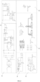
FIG. 2 is a circuit diagram of a control circuit according to a preferred embodiment of the present invention; -
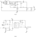
FIG. 3 is a circuit diagram of a power supply circuit according to a preferred embodiment of the present invention; -
FIG. 4 is a circuit diagram of an auxiliary circuit according to a preferred embodiment of the present invention; -
FIG. 5 is a circuit diagram of a radio frequency receiving circuit according to a preferred embodiment of the present invention; -
FIG. 6 is a circuit diagram of a prompting circuit according to a preferred embodiment of the present invention; -
FIG. 7 is a circuit diagram of a motor driving circuit and a main control circuit according to a preferred embodiment of the present invention; -
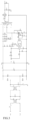
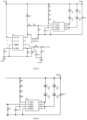
FIG. 8 is a circuit diagram of a lighting circuit according to a preferred embodiment of the present invention; -
FIG. 9 is a circuit diagram of a color adjustment circuit according to a preferred embodiment of the present invention; -
FIG. 10 is a perspective view of a lighting apparatus according to a preferred embodiment of the present invention; -
FIG. 11 is a schematic diagram of a lighting system according to a preferred embodiment of the present invention; -
FIG. 12 is a schematic diagram of control of the first control terminal of the lighting system inFIG. 11 ; and -
FIG. 13 is a schematic diagram of control of the second control terminal of the lighting system inFIG. 11 . - In order to make the objects, technical solutions and advantages of the present invention more apparent, the present invention will be described in detail with reference to the accompanying drawings and specific embodiments.
- It should be noted herein that, in order to avoid obscuring the present invention with unnecessary details, only the structures and/or processing steps closely related to the solutions of the present invention are shown in the accompanying drawings, and other details not closely related to the present invention are omitted.
- In addition, it is also to be noted that the terms "comprise," "include," or any variations thereof, are intended to cover a non-exclusive inclusion, such that a process, method, article, or device that includes a series of elements does not include only those elements but may include other elements not expressly listed or include other elements inherent to such process, method, article, or device.
- Referring to
FIGS. 1-9 , acontrol circuit 100 according to a preferred embodiment of the present invention is shown. Thecontrol circuit 100 is applied to alighting apparatus 200, and is configured to control the motor rotation of thelighting apparatus 200 and adjust the luminance and color temperature of thelighting apparatus 200. Thecontrol circuit 100 includes amain control circuit 10, amotor driving circuit 20, alighting circuit 30, and a power supply circuit 40 for supplying power to thecontrol circuit 100. - The power supply circuit 40 includes an EMI circuit 41, a rectifier circuit 42 and a switch circuit 43. The EMI circuit 41 is configured to suppress the interference of induction and radiation on external devices, prevent the mutual interference of peripheral electronic products, and improve the immunity of the
lighting apparatus 200, thus ensuring the working stability of thelighting apparatus 200. The rectifier circuit 42 converts AC voltage into DC voltage after bridge rectification. The output end of the rectified power supply circuit 40 is directly connected with thelighting circuit 30, and thelighting circuit 30 supplies power to thelight source assembly 240 in thelighting apparatus 200 by stepping down the rectified high voltage to a constant current through an inductor. In a preferred embodiment of the present invention, thelight source assembly 240 is an LED lamp bead. In other embodiments, thelight source assembly 240 can also be other light-emitting assemblies, such as a light bulb, a fluorescent lamp, a light bar or a light sheet, etc.. The present invention is not limited thereto. The output end of the rectified power supply circuit 40 is electrically connected with the input end of themotor driving circuit 20 and the input end of theauxiliary circuit 44 respectively through the switch circuit 43, so that the rectified high voltage can be supplied in the form of a constant output of 24V through a transformer to themotor driving circuit 20 and theauxiliary circuit 44. Theauxiliary circuit 44 steps down the voltage from 24V to 5V and then supplies power to themain control circuit 10. That is, the power supply system of themain control circuit 10 is 5V, so as to reduce the power consumption of thecontrol circuit 100. - The output ends of the
main control circuit 10 are connected with the input end of themotor driving circuit 20 and the input end of thelighting circuit 30 respectively, and themain control circuit 10 is configured to adjust the rotating speed of the motor in thelighting apparatus 200 through themotor driving circuit 20, so as to realize stepless speed adjustment of thelighting apparatus 200. Thelighting circuit 30 includes a first chip 31 and asecond chip 32. The first chip 31 is configured to detect the duty ratio of PWM output by themain control circuit 10, so as to control the luminance of thelighting apparatus 200. Thesecond chip 32 includes at least two color adjustment circuits with different color temperatures. Thesecond chip 32 is configured to control switching of the color temperature of thelighting apparatus 200 by controlling the connection of the color adjustment circuits. In this way, themotor driving circuit 20 and thelighting circuit 30 are directly controlled by onemain control circuit 10, and the rotating speed of the motor in thelighting apparatus 200 is controlled through themotor driving circuit 20, so as to realize stepless speed adjustment and stepless luminance adjustment of thelighting apparatus 200 while adjusting the color temperature. The color temperature and luminance of thelighting apparatus 200 are controlled through the first chip 31 and thesecond chip 32, so as to reduce the use of relays, meet the requirements of diversified functions of thelighting apparatus 200 and meanwhile reduce the cost of thelighting apparatus 200. - In a preferred embodiment of the present invention, the
main control circuit 10 is included in themotor driving circuit 20, and themain control circuit 10 in themotor driving circuit 20 controls themotor driving circuit 20 while also controlling thelighting circuit 30, so that the design of themain control circuit 10 in thelighting circuit 30 is simplified. In other embodiments, themain control circuit 10 may also be included in thelighting circuit 30, or themain control circuit 10 may be separately provided. The present invention is not limited thereto. Onemain control circuit 10 can control themotor driving circuit 20 and thelighting circuit 30 at the same time, so as to reduce the relay and part of AC/DC filter rectifier circuit, to reduce the cost. By integrating themotor driving circuit 20 and thelighting circuit 30, the color temperature and luminance of thelighting apparatus 200 and the rotating speed of the motor of thelighting apparatus 200 can be directly controlled by themain control circuit 10, so as to simplify the structure of thecontrol circuit 100 and reduce the cost. - In an alternative embodiment of the present invention, the
main control circuit 10 can be a programmable circuit module, and a plurality of IO ports are provided by programming the chip of themain control circuit 10 to realize output and input of different control signal. Those skilled in the art can carry out corresponding programming procedures according to the specific conditions of the circuit structure, which is not limited in the present invention. - In an alternative embodiment of the present invention, the
control circuit 100 further includes a radio frequency receiving circuit 50, the output end of the radio frequency receiving circuit 50 is connected with the signal input end of themain control circuit 10, and themain control circuit 10 is configured to receive the signal of the radio frequency receiving circuit 50, and send a motor driving signal to themotor driving circuit 20, and/or send a luminance signal and/or a color temperature signal to thelighting circuit 30 for lighting. That is, the radio frequency receiving circuit 50 is in signal connection with themain control circuit 10, and is in signal connection with themotor driving circuit 20 and/or thelighting circuit 30 through themain control circuit 10. According to the signal from the radio frequency receiving circuit 50, themain control circuit 10 can send a motor driving signal to themotor driving circuit 20 alone, or send a luminance signal or a color temperature signal for lighting to thelighting circuit 30 alone, or can select any combination of signals to send. The radio frequency receiving circuit 50 can receive a radio frequency signal such as WIFI, Bluetooth, etc., and convert the radio frequency signal into a digital signal and output it to themain control circuit 10, so as to control the rotating speed of the motor in thelighting apparatus 200 and the color temperature and luminance of thelighting apparatus 200 through themain control circuit 10. In a preferred embodiment, the radio frequency receiving circuit 50 adopts the frequency band of 433.92MHz to receive signals from a remote controller. In other embodiments, other frequency bands can also be adopted, which is not limited in the present invention. By providing the radio frequency receiving circuit 50, the remote control of thelighting apparatus 200 can be improved, and the user's convenience can be improved. - Optionally, the
control circuit 100 further includes a prompting circuit 60, the input end of the prompting circuit 60 is connected with the output end of the radio frequency receiving circuit 50, and the output end of the prompting circuit 60 is connected with the input end of themain control circuit 10. Preferably, the prompting circuit 60 is a buzzer, and the buzzer is in signal connection with the radio frequency receiving circuit 50 and themain control circuit 10. When the buzzer receives a radio frequency signal, the buzzer emits a "beep" sound to prompt the user, and executes the corresponding function. - Further, the motor of the
lighting apparatus 200 is a DC brushless motor, and the output end of themotor driving circuit 20 is connected to the three-phase connection terminal of the DC brushless motor. Themotor driving circuit 20 is configured to drive a MOSFET by detecting the duty ratio of PWM output by themain control circuit 10, and then control the three-phase current of the motor, and further control the rotating speed of the DC brushless motor. The AC motor of thelighting apparatus 200 is replaced by the DC brushless motor, so that thelighting apparatus 200 have the advantages of small starting current, low noise and convenient speed adjustment, and can realize stepless speed adjustment. - Further, the
lighting apparatus 200 includes a first chip 31 and asecond chip 32. The first chip 31 is configured to detect the duty ratio of PWM output by themain control circuit 10, so as to control the luminance of thelighting apparatus 200. Thesecond chip 32 includes at least two color adjustment circuits with different color temperatures, and thesecond chip 32 is configured to control switching of the color temperature of thelighting apparatus 200 by controlling the connection of the color adjustment circuits. By providing the first chip 31 and thesecond chip 32 instead of the relay, the color temperature of thelighting apparatus 200 can be adjusted, and at the same time, the stepless luminance adjustment of thelighting apparatus 200 can be realized. In addition, the cost of thecontrol circuit 100 can also be reduced by removing the relay. - In an alternative embodiment of the present invention, the first chip 31 is in signal connection with the radio frequency receiving circuit 50 and the
main control circuit 10, respectively. The first chip 31 includes an identification circuit and a first detection circuit. The identification circuit is configured to identify an output signal of themain control circuit 10 and control the connection of the first detection circuit. After themain control circuit 10 receives a signal from the radio frequency receiving circuit 50, themain control circuit 10 decodes the signal, outputs a corresponding ON/OFF/dimming signal according to the protocol, and controls the connection of the first detection circuit in the first chip 31. When the identification circuit of the first chip 31 identifies a low-level voltage, the first detection circuit is not turned on. When the identification circuit of the first chip 31 identifies a high-level voltage, the first detection circuit is turned on. When the identification circuit of the first chip 31 identifies a dimming signal, the first detection circuit detects the duty ratio of the PWM output by themain control circuit 10 to output a corresponding current, so as to control the luminance of thelighting circuit 30. The luminance can be adjusted from 0 to 100%, thus realizing the stepless luminance adjustment of thelighting apparatus 200. - In another alternative embodiment of the present invention, the first chip 31 is electrically connected with the
main control circuit 10, and in this case, themain control circuit 10 outputs a high-level voltage by default, that is, the first detection circuit is in an on state. At this time, the luminance of thelighting apparatus 200 is 100%. When themain control circuit 10 is turned off, the identification circuit of the first chip 31 identifies a low-level voltage or fails to identify a level voltage. At this time, the first detection circuit is not turned on, and the luminance of thelighting apparatus 200 is 0, that is, thelight source assembly 240 of thelighting apparatus 200 is in an off state. - In another alternative embodiment of the present invention, the first chip 31 can also realize the constant current output control of the
lighting apparatus 200. That is, when the first chip 31 detects an output overvoltage, short circuit or overtemperature of thelighting apparatus 200, the first chip 31 can turn off themain control circuit 10, thereby protecting thelighting apparatus 200 and prolonging the service life of thelighting apparatus 200. When the first chip 31 detects that the voltage, current and temperature of thelighting apparatus 200 are normal, themain control circuit 10 can be turned on, so that thelighting apparatus 200 can continue to be used. It can be known that the first chip 31 can also realize the constant current output control of thelighting apparatus 200 in other ways, which is not limited in the present invention. - In an alternative embodiment of the present invention, the first chip 31 is in signal connection with the
main control circuit 10, and thesecond chip 32 is in signal connection with themain control circuit 10 through the first chip 31. Thesecond chip 32 is configured to switch the color temperature of thelighting apparatus 200 by detecting a pin signal of the first chip 31. By thesecond chip 32 being in signal connection with themain control circuit 10 through the first chip 31, the design complexity of thelighting circuit 30 is reduced, thereby reducing the cost of thecontrol circuit 100. In other embodiments, thesecond chip 32 can also be directly in signal connection with themain control circuit 10, and the color temperature of thelighting apparatus 200 can be switched by the signal of themain control circuit 10, which is not limited in the present invention. - The
second chip 32 includes at least two color adjustment circuits with different color temperatures, and thesecond chip 32 is configured to control switching of the color temperature of thelighting apparatus 200 by controlling the connection of the color adjustment circuits. - In a preferred embodiment of the present invention, the
second chip 32 includes two color adjustment circuits with different color temperatures, that is, thesecond chip 32 is integrated with two thyristors of different color temperatures, and includes a color adjustment circuit with a first color temperature and a color adjustment circuit with a second color temperature, and the first color temperature is less than the second color temperature. When a lower color temperature is needed, thesecond chip 32 controls the color adjustment circuit with the first color temperature to be connected, and simultaneously controls the color adjustment circuit with the second color temperature to be disconnected, and at this time, the color temperature output by thelighting apparatus 200 is the first color temperature. When an intermediate color temperature is needed, thesecond chip 32 controls the color adjustment circuit of the first color temperature to be connected, and simultaneously controls the color adjustment circuit with the second color temperature to be connected, and at this time, the color temperature output by thelighting apparatus 200 is an average value of the first color temperature and the second color temperature. When a higher color temperature is needed, thesecond chip 32 controls the color adjustment circuit with the first color temperature to be disconnected, and simultaneously controls the color adjustment circuit with the second color temperature to be connected, and at this time, the color temperature output by thelighting apparatus 200 is the second color temperature. - Optionally, the
control circuit 100 further includes a memory circuit 70, and themotor driving circuit 20 and/or thelighting circuit 30 is connected with the memory circuit 70. In other words, the memory circuit 70 may only be connected with themotor driving circuit 20, so as to memorize the rotating speed of the motor of thelighting apparatus 200; or, the memory circuit 70 may only be connected with the first chip 31 in thelighting circuit 30, so as to memorize the luminance of thelighting apparatus 200; or, the memory circuit 70 may only be connected with thesecond chip 32 in thelighting circuit 30, so as to memorize the color temperature of thelighting apparatus 200; or, the memory circuit 70 may only be connected with both the first chip 31 and thesecond chip 32 in thelighting circuit 30, so as to memorize the luminance and color temperature of thelighting apparatus 200; or, the memory circuit 70 may be connected with both themotor driving circuit 20 and thelighting circuit 30, so as to memorize the rotating speed of the motor of thelighting apparatus 200 and the color temperature and luminance of thelighting apparatus 200. The present invention is not limited thereto. - The memory circuit 70 includes a storage circuit and a timing circuit. The storage circuit is configured to store a working state of the
lighting apparatus 200 before being turned off, and the timing circuit is configured to record a turning-off time of thelighting apparatus 200. Themain control circuit 10 is configured to compare the turning-off time with a state switching window time in length, and control switching of the working state of thelighting apparatus 200 according to a comparison result. The state switching window time can be set by oneself, preferably 1-2s. In the case where the turning-off time of thelighting apparatus 200 exceeds the state switching window time, the memory circuit 70 memorizes the working state of thelighting apparatus 200 before being turned off, and the next time thelighting apparatus 200 is turned on, it presents the working state of thelighting apparatus 200 before being turned off. In the case where the turning-off time of thelighting apparatus 200 is less than the state switching window time, the next time thelighting apparatus 200 is turned on, it presents a new working state of thelighting apparatus 200. The working state includes, but is not limited to, the rotating speed of the motor of thelighting apparatus 200, the color temperature of thelighting apparatus 200 and the luminance of thelighting apparatus 200. By providing the memory circuit 70, the first chip 31, whether it is in signal or electrical connection with themain control circuit 10, can synchronously realize the working state of thelighting apparatus 200. - In an alternative embodiment of the present invention, the memory circuit 70 is connected with the
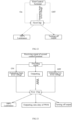
second chip 32 in thelighting circuit 30, so as to memorize the color temperature of thelighting apparatus 200. In the case where the turning-off time of thelighting apparatus 200 exceeds the state switching window time, the memory circuit 70 memorizes the color temperature of thelighting apparatus 200 before being turned off, and the next time thelighting apparatus 200 is turned on, it presents the color temperature of thelighting apparatus 200 before being turned off. In the case where the turning-off time of thelighting apparatus 200 is less than the state switching window time, the next time thelighting apparatus 200 is turned on, it switches to a next color temperature of thelighting apparatus 200. Preferably, the switching order of the color temperature is first color temperature > second color temperature > an average value of the first color temperature and the second color temperature. - Referring to
FIG. 10, FIG. 10 shows alighting apparatus 200 according to a preferred embodiment of the present invention. In the present embodiment, thelighting apparatus 200 is a fan lamp. In other embodiments, thelighting apparatus 200 can also be any other apparatus with a motor and a light-emitting component, which is not limited in the present invention. For the sake of clarity, in the following description, thelighting apparatus 200 is described by taking a fan lamp as an example. - The fan lamp includes a
ceiling assembly 210, asuspension assembly 220, afan assembly 230, alight source assembly 240 and acontrol assembly 250. Theceiling assembly 210 is used to connect with an installation foundation, and the installation foundation is used to hang the fan lamp. For example, the installation foundation can be a ceiling of a house, etc.. One end of thesuspension assembly 220 is accommodated in theceiling assembly 210, the other end of thesuspension assembly 220 is connected to thefan assembly 230 and thelight source assembly 240, and thelight source assembly 240 is located at one side of thefan assembly 230 away from thesuspension assembly 220. Thecontrol circuit 100 described above is applied in thecontrol assembly 250. The rotating speed of the motor in thefan assembly 230 and the color temperature and luminance of thelight source assembly 240 are controlled by theabove control circuit 100. In the present embodiment, thecontrol assembly 250 is installed above thefan assembly 230. In other embodiments, thecontrol assembly 250 can also be installed in other locations, such as within theceiling assembly 210, which is not limited in the present invention. - Referring to
FIGS. 11-13, FIGS. 11-13 show a lighting system according to a preferred embodiment of the present invention. The lighting system includes thelighting apparatus 200 described above, afirst control terminal 310 and/or asecond control terminal 320. Thefirst control terminal 310 is electrically connected with themain control circuit 10 of thelighting apparatus 200, thesecond control terminal 320 is in signal connection with themain control circuit 10 of thelighting apparatus 200, and the lighting system is configured to control the working state of thelighting apparatus 200 through thefirst control terminal 310 and/or thesecond control terminal 320. The working state of thelighting apparatus 200 includes, but is not limited to, the rotating speed of the motor of thelighting apparatus 200 and the color temperature and luminance of thelight source assembly 240 in thelighting apparatus 200; and the working state of thelighting apparatus 200 can be one or a combination of several of the rotating speed of the motor, the color temperature and the luminance of thelight source assembly 240. - In an alternative embodiment of the present invention, the
first control terminal 310 is a wall switch, and the wall switch is electrically connected with themain control circuit 10 of thelighting apparatus 200. The wall switch is configured to: when the color temperature of thelighting apparatus 200 needs to be adjusted, adjust the color temperature of thelighting apparatus 200 by the number of times the wall switch being pressed and the turning-off time of the wall switch. When the luminance of thelighting apparatus 200 needs to be adjusted, the wall switch is turned on, and at this time, themain control circuit 10 outputs a high-level voltage by default, and the luminance of thelighting apparatus 200 is 100%. The wall switch is turned off, and at this time, the identification circuit of the first chip 31 identifies a low-level voltage or fails to identify a level voltage, and the luminance of thelighting apparatus 200 is 0, that is, thelighting apparatus 200 is turned off. When the rotating speed of thelighting apparatus 200 needs to be adjusted, the wall switch is turned on, and at this time, themain control circuit 10 outputs a high-level voltage by default, and the motor of thelighting apparatus 200 is turned on at a preset speed. The wall switch is turned off, and at this time, thelighting apparatus 200 is turned off and the rotating speed is zero. Of course, in other embodiments, the wall switch can also be configured to adjust the luminance, color temperature and rotating speed of thelighting apparatus 200 by the number of times the wall switch being pressed and comparing the turning-off time of the wall switch. This principle is the same as that of adjusting the color temperature, and will not be repeated here. - In an alternative embodiment of the present invention, the
second control terminal 320 is a remote controller, and the remote controller is in signal connection with themain control circuit 10 of thelighting apparatus 200. The remote controller is configured to: realize switching of the color temperature of thelighting apparatus 200 by continuously operating a switch button on the remote controller; realize changing of luminance of thelighting apparatus 200 by continuously operating a luminance adjustment button on the remote controller; realize changing of the rotating speed of the motor of thelighting apparatus 200 by continuously operating a wind speed adjustment button on the remote controller. It can be known that the change of the luminance of thelighting apparatus 200 can be a stepless change or a segmented change. The change of the rotating speed of the motor of thelighting apparatus 200 can be a stepless change or a segmented change. The present application is not limited thereto. In a preferred embodiment of the present invention, the luminance of thelighting apparatus 200 is controlled by thesecond control terminal 320 to change steplessly, that is, the luminance of thelighting apparatus 200 can range from 0 to 100%. The rotating speed of the motor of thelighting apparatus 200 is controlled by thesecond control terminal 320 to change steplessly, that is, the rotating speed of the motor of thelighting apparatus 200 can range from 0 to 100%. The remote controller is in signal connection with themain control circuit 10 through radio frequency signals, so as to realize stepless speed adjustment, stepless luminance adjustment and color temperature switching of thelighting apparatus 200. - Taking luminance adjustment by the
second control terminal 320 as an example, when themain control circuit 10 receives a luminance adjustment signal from thesecond control terminal 320, themain control circuit 10 decodes the signal, outputs a corresponding ON/OFF/dimming signal according to the protocol, and controls the connection of the first detection circuit in the first chip 31. When the identification circuit of the first chip 31 identifies a low-level voltage, the first detection circuit is not turned on. When the identification circuit of the first chip 31 identifies a high-level voltage, the first detection circuit is turned on. When the identification circuit of the first chip 31 identifies a dimming signal, the first detection circuit detects the duty ratio of the PWM output by themain control circuit 10 to output a corresponding current, so as to control the luminance of thelighting circuit 30. The luminance can be adjusted from 0 to 100%, thus realizing the stepless luminance adjustment of thelighting apparatus 200. The principles of adjusting the color temperature and adjusting the rotating speed by thesecond control terminal 320 are the same as the principles of adjusting the color temperature and adjusting the rotating speed by themain control circuit 10 itself, which will not be repeated herein. - Optionally, the
second control terminal 320 can also be other terminals or a combination of various terminals, such as a mobile phone, a computer, etc.. The terminal is connected with thecontrol circuit 100 through the radio frequency receiving circuit 50, and the terminal sends a control signal. After the radio frequency receiving circuit 50 receives the signal sent by the terminal, the rotating speed of the motor of thelighting apparatus 200 and the color temperature and luminance of thelighting apparatus 200 are controlled and adjusted. - In an alternative embodiment, the lighting system includes a memory circuit 70, and the memory circuit 70 is connected with the
first control terminal 310 and also connected with thesecond control terminal 320 at the same time. The memory circuit 70 is configured to memorize the working state of thelighting apparatus 200 under the control of thefirst control terminal 310 and the working state of thelighting apparatus 200 under the control of thesecond control terminal 320, respectively, so as to synchronize the control of thefirst control terminal 310 and thesecond control terminal 320. The user can adjust the rotating speed, luminance and color temperature of thelighting apparatus 200 whether using thefirst control terminal 310 or using thesecond control terminal 320, so as to improve the convenience of the lighting system. - In summary, the
control circuit 100 of the present invention integrates themotor driving circuit 20 and thelighting circuit 30, themotor driving circuit 20 and thelighting circuit 30 are directly controlled through onemain control circuit 10, the rotating speed of the motor in thelighting apparatus 200 is controlled through themotor driving circuit 20, and the color temperature and luminance of thelighting apparatus 200 are controlled through the first chip 31 and thesecond chip 32, thus realizing stepless speed adjustment and stepless luminance adjustment of thelighting apparatus 200 while adjusting the color temperature, and meeting the requirements of diversified functions of thelighting apparatus 200. In addition, through the integration design, the relay and part of the filter rectifier circuit are removed, which simplifies the structure of thecontrol circuit 100 and reduces the cost. - The above embodiments are merely intended to illustrate rather than to limit the technical solutions of the present application. Although the present application is described in detail with reference to the preferred embodiments, those skilled in the art should understand that modifications or equivalent substitutions may be made to the technical solutions of the present application without departing from the spirit and scope of the technical solutions of the present application.
Claims (15)
- A control circuit, applied to a lighting apparatus (200), comprising a main control circuit (10), a motor driving circuit (20), a lighting circuit (30), and a power supply circuit (40) for supplying power to the control circuit (100), wherein output ends of the main control circuit (10) are respectively connected with an input end of the motor driving circuit (20) and an input end of the lighting circuit (30); the main control circuit (10) is configured to adjust a rotating speed of a motor in the lighting apparatus (200) through the motor driving circuit (20); the lighting circuit (30) comprises a first chip (31) and a second chip (32), and the first chip (31) is configured to detect a duty ratio of PWM output by the main control circuit (10), so as to control luminance of the lighting apparatus (200); the second chip (32) comprises at least two color adjustment circuits with different color temperatures, and the second chip (32) is configured to control switching of a color temperature of the lighting apparatus (200) by controlling connection of the color adjustment circuits.
- The control circuit according to claim 1, wherein the first chip (31) comprises an identification circuit and a first detection circuit; the identification circuit is configured to identify an output signal of the main control circuit (10) and control connection of the first detection circuit; and the first detection circuit is configured to detect the duty ratio of PWM output by the main control circuit (10), so as to control the luminance of the lighting circuit (30).
- The control circuit according to claim 1, wherein the first chip (31) is in signal connection or electrical connection with the main control circuit (10), and the second chip (32) is in signal connection with the main control circuit (10) through the first chip (31).
- The control circuit according to claim 1, wherein the motor driving circuit (20) and the lighting circuit (30) are directly connected with the main control circuit (10) through a wire harness.
- The control circuit according to claim 1, wherein the motor is a DC brushless motor, and the motor driving circuit (20) is configured to detect the duty ratio of PWM output by the main control circuit (10), so as to control a rotating speed of the DC brushless motor.
- The control circuit according to claim 1, wherein the control circuit (100) further comprises a radio frequency receiving circuit (50), an output end of the radio frequency receiving circuit (50) is connected with a signal input end of the main control circuit (10), and the main control circuit (10) is configured to receive a signal of the radio frequency receiving circuit (50), and send a motor driving signal to the motor driving circuit (20), and/or send a luminance signal and/or a color temperature signal to the lighting circuit (30) for lighting.
- The control circuit according to claim 6, wherein the control circuit (100) further comprises a prompting circuit (60), an input end of the prompting circuit (60) is connected with the output end of the radio frequency receiving circuit (50), and the output end of the prompting circuit (60) is connected with an input end of the main control circuit (10).
- The control circuit according to claim 1, wherein the control circuit (100) further comprises a memory circuit (70), and the motor driving circuit (20) and/or the lighting circuit (30) is connected with the memory circuit (70); the memory circuit (70) comprises a storage circuit and a timing circuit, the storage circuit is configured to store a working state of the lighting apparatus (200) before being turned off, the timing circuit is configured to record a turning-off time of the lighting apparatus (200), and the main control circuit (10) is configured to compare the turning-off time with a state switching window time in length, and control switching of the working state of the lighting apparatus (200) according to a comparison result.
- A lighting apparatus, wherein the control circuit (100) according to any one of claims 1-8 is applied.
- A lighting system, comprising the lighting apparatus (200) according to claim 9, a first control terminal (310) and/or a second control terminal (320), wherein the first control terminal (310) is electrically connected with the main control circuit (10) of the lighting apparatus (200), the second control terminal (320) is in signal connection with the main control circuit (10) of the lighting apparatus (200), and the lighting system is configured to control a working state of the lighting apparatus (200) through the first control terminal (310) and/or the second control terminal (320).
- The lighting system according to claim 10, wherein the working state of the lighting apparatus (200) comprises one or more of color temperature, luminance and a rotating speed of a motor of the lighting apparatus (200).
- The lighting system according to claim 10, wherein the lighting system further comprises a memory circuit (70), the first control terminal (310) and the second control terminal (320) are respectively configured to control the working state of the lighting apparatus (200), and the working state of the lighting apparatus (200) is synchronized through the memory circuit (70).
- The lighting system according to claim 10, wherein a switching order of the color temperature of the lighting apparatus (200) is: a first color temperature > a second color temperature > an average value of the first color temperature and the second color temperature.
- The lighting system according to claim 10, wherein the first control terminal (310) is a wall switch, and the wall switch is configured to adjust the working state of the lighting apparatus (200) by a count of times the wall switch being pressed and comparing a turning-off time of the wall switch.
- The lighting system according to claim 10, wherein the second control terminal (320) is a remote controller, and the remote controller is configured to: realize switching of color temperature of the lighting apparatus (200) by continuously operating a switch button on the remote controller; realize changing of luminance of the lighting apparatus (200) by continuously operating a luminance adjustment button on the remote controller; realize changing of a rotating speed of a motor of the lighting apparatus (200) by continuously operating a wind speed adjustment button on the remote controller; the second control terminal (320) is configured to control a stepless change of the luminance of the lighting apparatus (200); and/or the second control terminal (320) is configured to control a stepless change of the rotating speed of the motor of the lighting apparatus (200).
Applications Claiming Priority (3)
| Application Number | Priority Date | Filing Date | Title |
|---|---|---|---|
| CN202122911163.3U CN216673336U (en) | 2021-11-25 | 2021-11-25 | Control circuit, lighting device and lighting system |
| CN202111410757.4A CN114071825A (en) | 2021-11-25 | 2021-11-25 | Control circuit, lighting device and lighting system |
| PCT/CN2022/127608 WO2023093435A1 (en) | 2021-11-25 | 2022-10-26 | Control circuit, lighting apparatus, and lighting system |
Publications (2)
| Publication Number | Publication Date |
|---|---|
| EP4440246A1 true EP4440246A1 (en) | 2024-10-02 |
| EP4440246A4 EP4440246A4 (en) | 2025-06-04 |
Family
ID=86538836
Family Applications (1)
| Application Number | Title | Priority Date | Filing Date |
|---|---|---|---|
| EP22897518.1A Pending EP4440246A4 (en) | 2021-11-25 | 2022-10-26 | CONTROL CIRCUIT, LIGHTING APPARATUS AND LIGHTING SYSTEM |
Country Status (2)
| Country | Link |
|---|---|
| EP (1) | EP4440246A4 (en) |
| WO (1) | WO2023093435A1 (en) |
Families Citing this family (1)
| Publication number | Priority date | Publication date | Assignee | Title |
|---|---|---|---|---|
| CN116816703A (en) * | 2023-07-14 | 2023-09-29 | 深圳市怡芯智电子科技有限公司 | Fan lamp and fan lamp controller |
Family Cites Families (8)
| Publication number | Priority date | Publication date | Assignee | Title |
|---|---|---|---|---|
| US8035316B2 (en) * | 2008-07-10 | 2011-10-11 | Ming-Hui Lin | Current-limiting protection circuit of a remotely controlled ceiling fan-lamp |
| TWI565362B (en) * | 2014-10-23 | 2017-01-01 | 隆達電子股份有限公司 | Solid state light source device and dimming circuit thereof |
| CN206600294U (en) * | 2017-03-28 | 2017-10-31 | 蒋建龙 | A kind of modular construction of fan lamp |
| CN110784958A (en) * | 2019-11-12 | 2020-02-11 | 佛山市启正电气有限公司 | Integrated ceiling fan lamp and control method thereof |
| CN211509343U (en) * | 2020-03-19 | 2020-09-15 | 中山市迈笛电器有限公司 | Fan lamp integrated controller |
| CN212785952U (en) * | 2020-08-25 | 2021-03-23 | 峰岹科技(深圳)股份有限公司 | Control device based on ceiling fan lamp |
| CN214544162U (en) * | 2021-04-12 | 2021-10-29 | 江门市鸿基安普电子有限公司 | Three-core controlled DC ceiling fan control circuit with illumination function |
| CN114071825A (en) * | 2021-11-25 | 2022-02-18 | 欧普照明股份有限公司 | Control circuit, lighting device and lighting system |
-
2022
- 2022-10-26 WO PCT/CN2022/127608 patent/WO2023093435A1/en not_active Ceased
- 2022-10-26 EP EP22897518.1A patent/EP4440246A4/en active Pending
Also Published As
| Publication number | Publication date |
|---|---|
| EP4440246A4 (en) | 2025-06-04 |
| WO2023093435A1 (en) | 2023-06-01 |
Similar Documents
| Publication | Publication Date | Title |
|---|---|---|
| US11670957B2 (en) | Modular lighting panel | |
| EP2477460B1 (en) | Multi-stage power supply for a load control device having a low-power mode | |
| US7976189B2 (en) | Skylight LED lighting system | |
| US20150137692A1 (en) | Load control device for high-efficiency loads | |
| EP2635092B1 (en) | Method and System for avoiding Flicker for SSL devices | |
| US11930574B2 (en) | Drive circuit for a light-emitting diode light source | |
| US10802524B2 (en) | Adjustable electronic control system | |
| US9544965B1 (en) | Sensor lighting control system | |
| JP2009245834A (en) | Lighting fixture and lighting system | |
| JP2017503318A (en) | Dimmer system and dimming method | |
| CN216673336U (en) | Control circuit, lighting device and lighting system | |
| US20160119994A1 (en) | Solid State Light Source Device and Dimming Circuit Thereof | |
| JP2009301876A (en) | Led lighting system | |
| CN108293287B (en) | Lighting device control switch and method | |
| CN114071825A (en) | Control circuit, lighting device and lighting system | |
| WO2023093435A1 (en) | Control circuit, lighting apparatus, and lighting system | |
| WO2018040628A1 (en) | Bluetooth ceiling lamp fan | |
| US12041699B2 (en) | Lighting device | |
| CN201533439U (en) | Gradually dimmable lamp cup type cold light lamp control system | |
| EP3823421A1 (en) | Led-driver with pfc and wired bus interface | |
| US9674932B1 (en) | Dual sensor lighting controller with 1-button remote control | |
| CN218162949U (en) | AC touch light-adjusting desk lamp | |
| CN220910046U (en) | Lamp fan control circuit and lamp fan | |
| KR102828513B1 (en) | High-efficiency converter capable of phase-controlled dimming and RF wireless transmitter/receiver using the same | |
| CN101702859A (en) | Lamp cup type cold light lamp control system capable of adjusting light one by one |
Legal Events
| Date | Code | Title | Description |
|---|---|---|---|
| STAA | Information on the status of an ep patent application or granted ep patent |
Free format text: STATUS: THE INTERNATIONAL PUBLICATION HAS BEEN MADE |
|
| PUAI | Public reference made under article 153(3) epc to a published international application that has entered the european phase |
Free format text: ORIGINAL CODE: 0009012 |
|
| STAA | Information on the status of an ep patent application or granted ep patent |
Free format text: STATUS: REQUEST FOR EXAMINATION WAS MADE |
|
| 17P | Request for examination filed |
Effective date: 20240620 |
|
| AK | Designated contracting states |
Kind code of ref document: A1 Designated state(s): AL AT BE BG CH CY CZ DE DK EE ES FI FR GB GR HR HU IE IS IT LI LT LU LV MC ME MK MT NL NO PL PT RO RS SE SI SK SM TR |
|
| DAV | Request for validation of the european patent (deleted) | ||
| DAX | Request for extension of the european patent (deleted) | ||
| A4 | Supplementary search report drawn up and despatched |
Effective date: 20250507 |
|
| RIC1 | Information provided on ipc code assigned before grant |
Ipc: H02P 6/08 20160101ALI20250429BHEP Ipc: H05B 47/19 20200101ALI20250429BHEP Ipc: H02P 29/00 20160101ALI20250429BHEP Ipc: H05B 45/20 20200101ALI20250429BHEP Ipc: H05B 45/10 20200101AFI20250429BHEP |