EP4440211A1 - Verfahren und vorrichtung zur steuerung der aufwärtsstreckensynchronisation auf strahlbasis - Google Patents
Verfahren und vorrichtung zur steuerung der aufwärtsstreckensynchronisation auf strahlbasis Download PDFInfo
- Publication number
- EP4440211A1 EP4440211A1 EP22919014.5A EP22919014A EP4440211A1 EP 4440211 A1 EP4440211 A1 EP 4440211A1 EP 22919014 A EP22919014 A EP 22919014A EP 4440211 A1 EP4440211 A1 EP 4440211A1
- Authority
- EP
- European Patent Office
- Prior art keywords
- value
- information
- difference value
- base station
- terminal
- Prior art date
- Legal status (The legal status is an assumption and is not a legal conclusion. Google has not performed a legal analysis and makes no representation as to the accuracy of the status listed.)
- Pending
Links
Images


Classifications
-
- H—ELECTRICITY
- H04—ELECTRIC COMMUNICATION TECHNIQUE
- H04W—WIRELESS COMMUNICATION NETWORKS
- H04W16/00—Network planning, e.g. coverage or traffic planning tools; Network deployment, e.g. resource partitioning or cells structures
- H04W16/24—Cell structures
- H04W16/28—Cell structures using beam steering
-
- H—ELECTRICITY
- H04—ELECTRIC COMMUNICATION TECHNIQUE
- H04W—WIRELESS COMMUNICATION NETWORKS
- H04W56/00—Synchronisation arrangements
- H04W56/001—Synchronization between nodes
- H04W56/0015—Synchronization between nodes one node acting as a reference for the others
-
- H—ELECTRICITY
- H04—ELECTRIC COMMUNICATION TECHNIQUE
- H04B—TRANSMISSION
- H04B17/00—Monitoring; Testing
- H04B17/30—Monitoring; Testing of propagation channels
- H04B17/309—Measuring or estimating channel quality parameters
- H04B17/318—Received signal strength
- H04B17/328—Reference signal received power [RSRP]; Reference signal received quality [RSRQ]
-
- H—ELECTRICITY
- H04—ELECTRIC COMMUNICATION TECHNIQUE
- H04W—WIRELESS COMMUNICATION NETWORKS
- H04W24/00—Supervisory, monitoring or testing arrangements
- H04W24/10—Scheduling measurement reports ; Arrangements for measurement reports
-
- H—ELECTRICITY
- H04—ELECTRIC COMMUNICATION TECHNIQUE
- H04W—WIRELESS COMMUNICATION NETWORKS
- H04W56/00—Synchronisation arrangements
- H04W56/004—Synchronisation arrangements compensating for timing error of reception due to propagation delay
- H04W56/0045—Synchronisation arrangements compensating for timing error of reception due to propagation delay compensating for timing error by altering transmission time
-
- H—ELECTRICITY
- H04—ELECTRIC COMMUNICATION TECHNIQUE
- H04B—TRANSMISSION
- H04B7/00—Radio transmission systems, i.e. using radiation field
- H04B7/02—Diversity systems; Multi-antenna system, i.e. transmission or reception using multiple antennas
- H04B7/04—Diversity systems; Multi-antenna system, i.e. transmission or reception using multiple antennas using two or more spaced independent antennas
- H04B7/06—Diversity systems; Multi-antenna system, i.e. transmission or reception using multiple antennas using two or more spaced independent antennas at the transmitting station
- H04B7/0686—Hybrid systems, i.e. switching and simultaneous transmission
- H04B7/0695—Hybrid systems, i.e. switching and simultaneous transmission using beam selection
- H04B7/06952—Selecting one or more beams from a plurality of beams, e.g. beam training, management or sweeping
-
- H—ELECTRICITY
- H04—ELECTRIC COMMUNICATION TECHNIQUE
- H04W—WIRELESS COMMUNICATION NETWORKS
- H04W80/00—Wireless network protocols or protocol adaptations to wireless operation
- H04W80/02—Data link layer protocols
Definitions
- the present disclosure relates to a method and device for synchronizing and continuously tracking synchronization between a base station and a terminal in a wireless communication system.
- the 5G communication system or pre-5G communication system is called a Beyond 4G Network communication system or a Post LTE system.
- the 5G communication system set by 3GPP is called the New Radio (NR) system.
- NR New Radio
- the 5G communication system is being considered for implementation in ultra-high frequency (mmWave) band (e.g., 60 GHz band).
- mmWave ultra-high frequency
- ACM advanced coding modulation
- FQAM Hybrid FSK and QAM Modulation
- SWSC Sliding Window Superposition Coding
- FBMC Filter Bank Multi Carrier
- NOMA non-orthogonal multiple access
- SCMA sparse code multiple access
- IoT Internet of Things
- IoE Internet of Everything
- sensing technology wired and wireless communication and network infrastructure, service interface technology, and security technology
- M2M Machine to Machine
- MTC Machine Type Communication
- IoT may be applied to fields such as a smart home, a smart building, a smart city, a smart car or a connected car, a smart grid, health care, smart home appliances, and advanced medical service through convergence and combination of existing information technology (IT) and various industries.
- IT information technology
- 5G communication system to the IoT network.
- technology such as sensor network, Machine to Machine (M2M), and Machine Type Communication (MTC) are being implemented by the 5G communication technology such as beamforming, MIMO, and array antenna.
- M2M Machine to Machine
- MTC Machine Type Communication
- the application of cloud RAN as a big data processing technology described above may also be said to be an example of the convergence of the 5G technology and the IoT technology.
- the present disclosure proposes a method and device for controlling and tracking uplink synchronization in a beamforming-based wireless communication system.
- the present disclosure proposes a method of obtaining DL sync for each transmission (Tx) beam of a base station and reporting DL Sync difference information for each beam to the base station through beam-related reporting.
- a method for aligning uplink synchronization by a terminal in wireless communication system may comprise obtaining a difference value between first downlink synchronization based on a synchronization signal/physical broadcast channel, SS/PBCH, block corresponding a first beam and second downlink synchronization based on a SS/PBCH block corresponding a second beam.
- the method may comprise transmitting, based on comparison between the second downlink synchronization and cyclic prefix, CP, length, reporting information comprising information associated with the difference value to a base station.
- the method may comprise receiving, from the base station, information on a timing advance, TA, value derived based on the information associated with the difference value.
- information associated with the difference value may be comprised in the reporting information.
- the method may comprise measuring a reference signal received power, RSRP, value based on each of SS/PBCH block corresponding a different beam of the base station.
- the method may comprise selecting, based on the RSRP value, one or more candidate beams among a plurality of beams of the base station.
- the method may comprise selecting a beam corresponding to the smallest value among difference values between downlink synchronization associated with each of the one or more candidate beams and the first downlink synchronization, as the second beam.
- the reporting information may comprise a SS/PBCH block index corresponding to the second beam, the RSRP value, and the difference value.
- indexes corresponding to range of difference value is pre-defined based on the first downlink synchronization, and index corresponding to the obtained difference value may be comprised in the reporting information.
- the reporting information may comprise 1-bit information indicating that the SS/PBCH block index corresponding to the second beam, a reference signal received power, RSRP, value, and the TA value need to be updated.
- the information on the TA value may be comprised on medium access control element, MAC CE, command comprising information indicating a change from the first beam to the second beam.
- MAC CE medium access control element
- the method may comprise receiving configuration information comprising a request to report the information associated with the difference value.
- a method performed by a base station in a wireless communication system may comprise transmitting, based on a plurality of beams of the base station, a plurality of synchronization signal/physical broadcast channel, SS/PBCH, blocks to a terminal.
- the method may comprise receiving reporting information comprising information associated with a difference value between first downlink synchronization based on a SS/PBCH block corresponding a first beam and second downlink synchronization based on a SS/PBCH block corresponding a second beam, from the terminal.
- the method may comprise transmitting information on a timing advance, TA, value derived based on the information associated with the difference value to the terminal.
- the information associated with the difference value may be comprised in the reporting information based on comparison between the second downlink synchronization and cyclic prefix, CP, length.
- a terminal of a wireless communication system may comprise a transmit/receive unit configured to transmit and receive signals, and a control unit controlling the transmit/receive unit.
- the control unit may be configured to obtain a difference value between first downlink synchronization based on a synchronization signal/physical broadcast channel, SS/PBCH, block corresponding a first beam and second downlink synchronization based on a SS/PBCH block corresponding a second beam.
- the control unit may be configured to transmit, based on comparison between the second downlink synchronization and cyclic prefix, CP, length, reporting information comprising information associated with the difference value to a base station.
- the control unit may be configured to control to receive, from the base station, information on a timing advance, TA, value derived based on the information associated with the difference value.
- a base station of a wireless communication system may comprise a transmit/receive unit that transmits a plurality of SS/PBCH blocks to a terminal based on a plurality of beams of the base station, and a control unit controlling the transmit/receive unit.
- the control unit may be configured to receive reporting information comprising information associated with a difference value between first downlink synchronization based on a SS/PBCH block corresponding a first beam and second downlink synchronization based on a SS/PBCH block corresponding a second beam, from the terminal.
- the control unit may be configured to control transmitting information on a timing advance, TA, value derived based on the information associated with the difference value to the terminal.
- the information associated with the difference value may be comprised in the reporting information based on comparison between the second downlink synchronization and cyclic prefix, CP, length.
- uplink synchronization and tracking can be achieved without uplink disconnection even when a beam changes.
- a beam with a good RSRP can be utilized.
- data throughput can be improved while preventing wireless connection failure.
- each block of the process flowchart drawings and combinations of the flowchart drawings may be performed by computer program instructions. Since these computer program instructions may be mounted on a processor of a general-purpose computer, a special-purpose computer, or other programmable data processing equipment, the instructions, performed through the processor of the computer or other programmable data processing equipment, generate a means of performing functions described in flowchart block(s).
- these computer program instructions may also be stored in a computer-usable or computer-readable memory that may be directed toward a computer or other programmable data processing equipment to implement the function in a particular manner, the instructions stored in the computer-usable or computer-readable memory may also be capable of producing an article of manufacture involving the instruction means performing the function described in the flowchart block(s). Since the computer program instructions may also be mounted on the computer or other programmable data processing equipment, it is also possible for a series of operational steps to be performed on the computer or other programmable data processing equipment to generate a computer-executed process so that the instructions that perform the computer or other programmable data processing equipment provide steps for executing the functions described in the flowchart block(s).
- each block may represent a portion of a module, segment, or a code including one or more executable instructions for executing a specified logical function(s).
- a 5G communication system should support a service that simultaneously satisfy various requirements so that the various requirements of a user and service provider may be freely reflected.
- Services considered for the 5G communication system include enhanced mobile broadband (eMBB), massive machine type communication (mMTC), ultra reliability low latency communication (URLLC), and so on.
- the eMBB aims to provide a more improved data transmission rate than the existing data transmission rate supported by LTE, LTE-A, or LTE-Pro.
- the eMBB should be able to provide a peak data rate of 20 Gbps in downlink and a peak data rate of 10 Gbps in uplink from a perspective of one base station.
- the 5G communication system should provide the peak data rate and at the same time provide an increased user perceived data rate of a terminal.
- improvement in various transmission and reception technologies may be required, including more advanced multiple-antenna (or multi input multi output (MIMO)) transmission technology.
- MIMO multi input multi output
- signals are transmitted by using a transmission bandwidth of up to 20 MHz in the 2 GHz band, while the 5G communication system may meet the data transmission rate required by the 5G communication system by using a wider frequency bandwidth than 20 MHz in the frequency band of 3 to 6 GHz or above 6 GHz.
- the mMTC is being considered to support an application service such as Internet of Thing (IoT) in the 5G communication system.
- IoT Internet of Thing
- the mMTC requires support for access to a large scale of terminal within a cell, improved coverage of the terminal, improved battery time, and reduced cost of the terminal. Since the IoT provides a communication function by being attached to various sensors and various devices, it should be able to support a large number of terminals (e.g., 1,000,000 terminals/km2) within the cell.
- the terminal supporting the mMTC is likely to be located in a shaded area that cannot be covered by the cell, such as a basement of a building, and therefore require wider coverage compared than other services provided by the 5G communication system.
- the terminal supporting the mMTC should be configured as a low-cost terminal, and since it is difficult to frequently replace a battery of the terminal, a very long battery life time such as 10 to 16 years is required.
- the URLLC it is a cellular-based wireless communication service used for a mission-critical.
- a service used for remote control for robot or machinery, industrial automation, unmanned aerial vehicle, remote health care, emergency alert, and so on may be considered. Therefore, the communication provided by the URLLC should provide very low latency and very high reliability.
- a service supporting the URLLC should meet an air interface latency of less than 0.5 milliseconds and at the same time meet a requirement of a packet error rate of 10-5 or less. Therefore, for the service supporting the URLLC, the 5G system should provide a smaller transmit time interval (TTI) than other services, and at the same time, it should allocate a wide range of resources in the frequency band to ensure the reliability of a communication link.
- TTI transmit time interval
- Three services of the 5G communication system may be multiplexed and transmitted in one system.
- different transmission/reception techniques and transmission/reception parameters may be used between services to satisfy different requirements of each service.
- an orthogonal frequency division multiplexing (OFDM) method is adopted as one of the multiple access methods, and time-frequency resource for carrying data or control information for each user are usually allocated and operated so that they do not overlap, that is, orthogonality is established, so that each user's data or control information is distinguished.
- OFDM orthogonal frequency division multiplexing
- LTE Long Term Evolution
- LTE-A Long Term Evolution
- NR new radio
- 5G new radio
- a base station is a subject that performs resource allocation of the terminal, and may be at least one of gNode B, eNode B, Node B, Base Station (BS), a wireless access unit, a base station controller, or a node on a network.
- the terminal may include a user equipment (UE), a mobile station (MS), a cellular phone, a smartphone, a computer, or a multimedia system capable of performing a communication function.
- downlink is a wireless transmission path of a signal transmitted by the base station to the terminal
- uplink refers to a wireless transmission path of a signal transmitted by the terminal to the base station.
- FIG. 1 is an example for explaining a type and definition of synchronization in a wireless communication system.
- synchronization may be divided into reference synchronization, downlink (DL) synchronization, and uplink (UL) synchronization.
- DL downlink
- UL uplink
- the synchronization may be expressed as "Sync".
- use of this term does not limit technical scope of the present disclosure.
- the reference synchronization may refer to synchronization that is a reference of a base station. All transmit/receive signals of the base station should be encoded/decoded based on the corresponding reference synchronization.
- the DL synchronization may refer to synchronization that is a reference of DL operation of a terminal.
- the terminal may detect a radio boundary (i.e., the exact timing when a radio frame starts) and an OFDM symbol boundary (i.e., the exact timing when the OFDM symbol starts) through the DL synchronization process.
- the DL synchronization may mean synchronization (reference Sync + DL path delay) in which propagation delay of the DL path is added to the reference synchronization.
- the propagation delay may be interpreted as a path delay of a corresponding path.
- the terminal may identify the exact timing at which uplink data (e.g., PUSCH/PUCCH) should be transmitted.
- the UL synchronization may be defined as how fast UL transmission is performed compared to the DL synchronization (i.e., terminal synchronization).
- the UL synchronization may be described by ⁇ DL Sync-Timing Advance value ⁇ .
- the UL synchronization may finally be defined as indicating how fast UL should be transmitted to meet reference synchronization (i.e., base station synchronization) compared to the DL synchronization (i.e., terminal synchronization), and the quantitative value of how fast UL should be transmitted may be defined as the propagation delay of the UL path as in DL (e.g., DL Sync - UL path delay).
- the UL path delay may be interpreted as a propagation delay of the UL path.
- cyclic prefix is inserted in front of each OFDM symbol to reduce interference between symbols. That is, a signal of a last section of a valid symbol section is copied and inserted in front of the valid symbol.
- a transmitted signal is in a form of a sine wave in which amplitude and phase change from one symbol to the next.
- the amplitude and phase at the beginning of each symbol are the same as the amplitude and phase at the end.
- receiving-end receives signals transmitted through a plurality of paths with different arrival times. In this case, when CP length is longer than delay spread, the receiving-end may still read information from one symbol at a time.
- FFT symbol fast fourier transform
- EVM error vector magnitude
- the terminal may obtain and track the DL Sync based on synchronization signal (SS)/physical broadcast channel (PBCH) block transmitted by the base station. Specifically, the terminal obtains the DL Sync by measuring the SS/PBCH block transmitted by the base station by itself, and continuously measure the difference from the previous DL Sync by measuring the SS/PBCH block transmitted periodically, and reflecting this in the DL Sync to track it.
- SS/PBCH block refers to a physical layer channel block configured with Primary SS (PSS), Secondary SS (SSS), and PBCH, and is specifically as follows.
- FIG. 2 is a diagram illustrating an example in which a plurality of SS/PBCH blocks are transmitted by using different beams.
- SS/PBCH block in NR is configured with PSS, SSS, and PBCH, and may be transmitted in plurality to a terminal.
- Each SS/PBCH block may be transmitted to the terminal by using a different beam, respectively.
- the SS/PBCH block illustrated in FIG. 2 is transmitted by using beams #0, #1, #2, and #3, respectively.
- Master information block (MIB) information transmitted through the PBCH may include information such as system frame number (SFN), most significant bit (MSB) of the SS/PBCH block index, half frame timing, subcarrier spacing for common control, SS/PBCH subcarrier offset, SIB1 PDCCH configuration, and total payload size.
- SFN system frame number
- MSB most significant bit
- the MSB of the SS/PBCH block index enables transmission of a plurality of SS/PBCH blocks by providing MSB information of the SS/PBCH block index to support the plurality of SS/PBCH blocks.
- the terminal may proceed with random access procedure required for initial access by transmitting a beam-based physical random access channel (PRACH) to a base station by using PRACH resource allocated for each SS/PBCH block.
- PRACH physical random access channel
- the terminal may obtain DL synchronization by detecting the SS/PBCH block and decode system information.
- the terminal may identify a structure of an SS/PBCH block burst set based on the detected SS/PBCH block index, and may detect a symbol/slot/half-frame boundary accordingly.
- the number of a frame/half-frame to which the detected SS/PBCH block belongs may be identified by using SFN information and half-frame indication information.
- the terminal may obtain 10-bit SFN information from the PBCH.
- the 10-bit SFN information 6 bits are obtained from the MIB, and the remaining 4 bits are obtained from PBCH Transport Block (TB).
- TB PBCH Transport Block
- the terminal may obtain 1-bit half-frame indication information.
- the half-frame indication information may be implicitly signaled by using PBCH DMRS.
- the terminal may obtain the SS/PBCH block index based on DMRS sequence and PBCH payload.
- An SS/PBCH block candidate is indexed from 0 to L-1 according to time order within the SS/PBCH block burst set (i.e., half-frame).
- L Least Significant Bit
- MSB 3 bits of the S S/PBCH block index
- PBCH PBCH
- LSB 2 bits of the SS/PBCH block index may be indicated by using four different PBCH DMRS sequences.
- L 4 among the 3 bits that may be indicated by using eight PBCH DMRS sequences, the 1 bit remaining after indicating the SS/PBCH block index may be used for half-frame indication.
- Initial UL synchronization may be obtained during a RACH process of initial access.
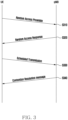
- FIG. 3 is an example illustrating a random access procedure of a terminal.
- a terminal may detect a synchronization signal in a SS/PBCH block and decode PBCH.
- the terminal may obtain downlink synchronization based on the synchronization signal and the PBCH, and decode system information.
- the terminal may identify preamble format, time, and frequency resource based on the system information, and may transmit a random access preamble (hereinafter, interchangeable with Msg1) through PRACH (S310).
- a base station After receiving the Msg1, a base station transmits PDCCH for transmission of Msg2 (hereinafter, interchangeable with a random access response (RAR)) to the terminal, and transmits the Msg2 to a resource allocated through the PDCCH (S320).
- RAR random access response
- the base station may transmit a corresponding timing advance value to the terminal by including it in the Msg2. Through this, the terminal may obtain initial UL synchronization. Thereafter, the terminal informs the base station that the corresponding Msg2 has been successfully received by transmitting Msg3 (hereinafter, interchangeable with scheduled transmission) to the base station (S330), and thereafter, the base station informs that contention has been resolved by transmitting a contention resolution message on PDSCH (S340).
- Msg3 hereinafter, interchangeable with scheduled transmission
- the base station should control the terminal to track UL Sync by transmitting an appropriate timing advance value to the terminal when the terminal connects or moves for the first time, especially when the beam changes in a beamforming-based system, and this may be referred to as UL Sync tracking.
- the UL Sync tracking after the initial UL synchronization may allow the terminal to track UL synchronization by calculating the timing advance (TA) value, and transmitting it to the terminal through a timing advance command medium access control (MAC) control element (CE).
- TA timing advance
- CE timing advance command medium access control
- a method of controlling timing advance through MAC CE is examined in more detail.
- the timing advance command MAC CE may be indicated for a timing advance group (TAG).
- TAG timing advance group
- the timing advance group may mean a serving cell group that is configured by RRC and uses the same timing reference cell and the same timing advance value for a cell in which UL is configured.
- a timing advance group including SpCell of MAC entity is referred to as a primary timing advance group (PTAG), while the term secondary timing advance group (STAG) refers to another TAG.
- the timing advance command MAC CE may be identified by a MAC subheader having LCID. It may have a fixed size and may be configured as a single octet, defined as follows:
- the terminal may be provided with a value N TA,offset of the timing advance offset for the serving cell by n-TimingAdvanceOffset for the serving cell.
- the terminal may determine a default value.
- the same timing advance offset value N TA,offset may be applied to both carriers.
- the terminal that has received the timing advance command for the TAG may adjust uplink timing for PUSCH/SRS/PUCCH transmission in all serving cells of the TAG based on i) the value N TA,offset that the terminal expects to be the same for all serving cells of the TAG, and ii) the received timing advance command where the uplink timing for PUSCH/SRS/PUCCH transmission is the same for all serving cells of the TAG.
- the timing advance command for the TAG may indicate a change in UL timing relative to the current uplink timing for the TAG as a multiple of 16 ⁇ 64 ⁇ T c /2 ⁇ .
- N TA is relative to the SCS of a first uplink transmission from the UE after receiving the random access response or the absolute timing advance command MAC CE.
- N TA _ new N TA _ old + T A ⁇ 31 ⁇ 16 ⁇ 64/2 ⁇ .
- Adjusting the N TA value to a positive or negative number means advancing or delaying the uplink transmission timing for the TAG by the corresponding amount, respectively.
- the base station processes multiple terminals, and the base station needs to ensure that a UL signal from all terminals must be aligned with a common receiver timer of the base station. Therefore, it is necessary to adjust Tx timing (UL timing) of each terminal.
- Tx timing UL timing
- a difference in path delay compared to the initial path occurs only when the terminal moves, and even when the difference in path delay occurs, the difference in path delay caused by the terminal movement may not be significant. In this case, it may not be a problem to use the existing timing advance control method that measures the timing offset in the UL signal (e.g., PUSCH) and updates the TA value for UL Sync through the timing advance command MAC CE.
- the existing timing advance control method that measures the timing offset in the UL signal (e.g., PUSCH) and updates the TA value for UL Sync through the timing advance command MAC CE.
- a large path delay may occur not only by the movement of the terminal but also by beam change.
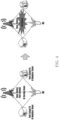
- FIG. 4 illustrates an example of a beam change due to occurrence of a blockage on a serving beam in an environment where various path delays exist for each beam between a base station and a terminal.
- a beam change to a neighbor beam may be performed.
- the path delay is different for each path, a large path delay difference may occur even due to the beam change.
- UL Sync may be damaged.
- the propagation delay (i.e., path delay) of the beam to be changed is longer than a CP length, orthogonality of an OFDM symbol may be broken, causing EVM to increase and UL sync to be broken.
- FIG. 4 illustrates an example in which a path delay of neighbor beams is longer than that of the serving beam, but of course, there may also be a case in which a path delay of the neighbor beam is shorter than that of the serving beam.
- FIG. 5 is an example illustrating an entire beam change process in NR standard.
- a beam management process using SSB (1) a beam change request process based on SSBRI reported by a terminal to a base station (2), a channel measurement process based on CSI-RS received through the changed beam (3), and a DL data transmission process (4) are illustrated.
- it is defined to transmit up to four SSBRI and RSRP pairs in the beam management process using the SSB.
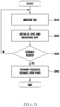
- FIG. 6 illustrates an example of a detailed procedure of a DL beam management process 1 by using SSB according to an embodiment of the present disclosure.
- a terminal may measure SSB received from a base station (S610).
- the base station may transmit a plurality of SSBs to the terminal through different transmission (Tx) beams.
- SSB resources used for beam management may be set based on configuration information (e.g., CSI-ResourceConfig IE) transmitted from the base station.
- the configuration information may include a list (e.g., CSI-SSB-ResourceSetList) of the SSB resources used for beam management and reporting in one resource set.
- an SSB resource set may be set to ⁇ SSBx1, SSBx2, SSBx3, SSBx4, ... ⁇ .
- SSB index may be defined from 0 to 63.
- the SSB index 0, SSB index 1, ..., and SSB index 63 may correspond to different Tx beams (e.g., beam #0, beam #1, ..., and beam #63) of the base station, respectively.
- the terminal may measure RSRP for the SSB resources and obtain DL Sync (S620).
- the terminal may determine whether a feedback request has been received from the base station (S630). For example, in case that a reportQuantity of CSI report configuration information (e.g., CSI-reportConfig) is set as a parameter (e.g., ssb-Index-RSRP) that indicates reporting on SSB resource indicator (SSBRI) and reference signal received power (RSRP), the terminal may determine that the feedback request has been received.
- CSI-reportConfig e.g., CSI-reportConfig
- SSBRI SSB resource indicator
- RSRP reference signal received power
- the terminal may transmit feedback information to the base station (S640).
- the feedback information may include a beam ID (e.g., SSBRI) and RSRP Pair corresponding thereto.
- the base station has no choice but to select a beam based only on RSRP signal strength. That is, in case that the base station selects a beam based only on the RSRP signal strength, a beam with a large path delay may be selected, which may cause a problem in UL Sync.
- FIG. 7 illustrates an example of beams of different paths according to an embodiment of the present disclosure. Although FIG. 7 illustrates two paths as an example for convenience of description, three or more paths may exist in a beamforming-based communication system.
- a path length of a serving beam is 90 meters and a path length of a neighbor beam is 150 meters. Since the path length of each beam is different, each beam may have a different path delay.
- a method for updating/tracking UL synchronization i.e., a method for controlling timing advance
- a method for using a beam with good RSRP even if the path delay is long proposes a method in which a terminal measures a DL Sync difference between the serving beam and the neighbor beam, and reports information on the DL Sync difference to a base station through beam-related feedback (e.g., beam CSI reporting).
- a method is proposed in which the base station may respond to a rapid UL Sync error experienced when changing the beam by transmitting a timing advance value determined based on the reported value to the terminal along with a beam change request.
- FIG. 8 is an example illustrating a method of obtaining DL sync difference information for each Tx beam of a base station by a terminal according to an embodiment of the present disclosure.
- a terminal may obtain DL Sync for each Tx beam of a base station. That is, the terminal may obtain the DL sync of a serving beam and the DL Sync of a neighbor beam, respectively. As described above, the terminal may receive SSBs transmitted through different Tx beams of the base station and obtain the DL sync based on SSB corresponding to each beam. In addition, the terminal may measure the difference between the DL Sync of the serving beam (e.g., first beam) and the DL Sync of the neighbor beam (e.g., second beam). The terminal may directly store the measured difference value (e.g., DL Sync Delta), or convert it into a timing advance value and store it.
- the measured difference value e.g., DL Sync Delta
- FIG. 9 illustrates an example of a beam feedback operation procedure of a terminal according to an embodiment of the present disclosure.
- a terminal may receive SSB from a base station and measure the received SSB (S910).
- the SSB may mean an SS/PBCH block, and each SSB (SS/PBCH block) may include a synchronization signal (SS) and a physical broadcast channel (PBCH).
- SS synchronization signal
- PBCH physical broadcast channel
- each SSB may correspond to different beams of the base station. That is, the base station may transmit the SSB to the terminal through different Tx beams.
- the terminal may obtain DL synchronization and measure RSRP based on the SSB (S920).
- the terminal may determine whether the current beam is a serving beam (e.g., first beam) (S930).
- a serving beam e.g., first beam
- DL Sync information of the serving beam may be obtained and stored (S941).
- a difference between the DL Sync of the previously stored serving beam and the DL Sync of the current beam may be calculated and stored (S942).
- a difference value between the DL Sync e.g., first DL Sync
- the DL Sync e.g., second DL Sync
- the current beam e.g., second beam, not the serving beam
- the operation of the steps S910 to S942 may be performed repeatedly as many times as the set number of SSB resources. That is, the terminal may receive a plurality of SSBs based on a plurality of beams of the base station, and each SSB may correspond to a different Tx beam. In addition, the terminal may measure DL Sync and RSRP value for each SSB.
- the terminal may determine whether a feedback request has been received from the base station (S950).
- the terminal may receive configuration information (e.g., CSI-reportConfig IE) associated with feedback reporting from the base station, and in a case where "reportQuantity" included in the configuration information is set as a parameter (e.g., ssb-Index-RSRP) representing reporting on SSBRI and RSRP (Reference Signal Received Power), the terminal may determine that the feedback request has been received.
- configuration information e.g., CSI-reportConfig IE
- a parameter e.g., ssb-Index-RSRP
- SSBRI and RSRP Reference Signal Received Power
- a new "reportQuantity” value may be defined to explicitly indicate feedback reporting (e.g., information associated with DL Sync difference value) related to the DL Sync.
- feedback reporting e.g., information associated with DL Sync difference value
- a parameter e.g., ssb-Index-RSRP-DLSyncdelta
- the terminal may determine that the feedback request has been received.
- the terminal may transmit feedback information (i.e., reporting information) to the base station (S960).
- the feedback information may be transmitted based on an uplink channel (e.g., PUCCH and PUSCH).
- the feedback information may include Beam ID (e.g., SSBRI), RSRP, and information (e.g., DL Sync Delta Tuple) associated with the difference value between the DL Sync of the serving beam and the DL Sync of the current beam.
- the information e.g., DL Sync Delta Tuple
- the information e.g., DL Sync Delta Tuple
- the information (e.g., DL Sync Delta Tuple) associated with the difference value may be configured as the difference value (i.e., delta) between the DL sync of the serving beam and the DL sync of the neighbor beam.
- the difference value may be expressed as
- the terminal may report up to four SSBRI and RSRP pairs. Therefore, each DL sync difference value of SSBs corresponding to the reported SSBRI may be reported to the base station.
- the information associated with the difference value may include DL Sync delta 1 between the serving beam and a neighbor beam #1, DL Sync delta 2 between the serving beam and a neighbor beam #2, ..., and DL Sync delta n between the serving beam and a neighbor beam #n.
- a range of the difference value (i.e., Delta) may be divided into N sections, and an index corresponding to each section may be pre-defined.
- the corresponding relationship between the index and Delta range may be pre-defined as illustrated in Table 1.
- the corresponding relationship of the Table 1 may be set to higher layer signaling (e.g., RRC).
- RRC layer signaling
- an index corresponding to the obtained difference value may be included and reported in the reporting information.
- the Table 1 is only an example for convenience of description and does not limit the technical scope of the present disclosure.
- the range of the difference value may be further subdivided and may be fed back to 3 bits or more, or resolution of the range may be lowered and the range of the difference value may be fed back to less than 2 bits.
- the number of bits required for feedback may be reduced by comparing the DL Sync delta value feedback method.
- the terminal may determine that new TA control is necessary based on the measured difference value and explicitly request that the base station send a new TA value by using 1-bit signaling.
- the feedback information may include 1-bit information indicating that a SS/PBCH block index corresponding to a second beam, the RSRP value, and the TA value need to be updated.
- the base station may know that the new TA value should be transmitted to the terminal when changing to the second beam through the 1-bit information.
- the terminal may compare the DL sync of a beam (e.g., second beam) other than the serving beam with the CP length, and based on this, report feedback information including information (e.g., difference value, index corresponding to the difference value, and the like) associated with the difference value to the base station.
- a beam e.g., second beam
- information e.g., difference value, index corresponding to the difference value, and the like
- the terminal may select an SSB resource having the best RSRP value among SSB resources.
- information associated with the difference value may be reported to the base station.
- the terminal may transmit feedback information including i) a beam ID (e.g., SSB resource identifier) corresponding to the selected SSB resource, ii) an RSRP value measured based on the selected SSB resource, and iii) information associated with a difference value between DL Sync obtained based on the selected SSB resource and DL Sync obtained based on the SSB corresponding to the serving beam to the base station.
- a beam ID e.g., SSB resource identifier
- the information associated with the difference value may include the difference value itself, a value converted from the difference value to a specific time unit, or an index corresponding to the difference value.
- the DL Sync value obtained based on the selected SSB resource does not exceed the CP length, only SSBRI and RSRP may be reported as in a conventional method.
- the terminal may report up to four SSBRI and RSRP pairs.
- the reported SSBRI may be determined according to the RSRP measured based on the SSB resource. Therefore, up to four pieces of information associated with the DL sync difference value corresponding to the reported SSBRI may also be reported. Even in this case, information associated with the DL sync difference value may be reported only for a beam having DL Sync exceeding the CP length. For a specific example, it is assumed that SSB #1, SSB #2, SSB #3, and SSB #4 are reported.
- DL sync of a beam associated with SSB #2 and SSB #3 may exceed the CP length, and DL sync of a beam associated with SSB #1 and SSB #4 may not exceed the CP length.
- the terminal may report ⁇ SSB#1 and RSRP for SSB#1 ⁇ , ⁇ SSB#2, RSRP for SSB#2, and DL sync delta #2 ⁇ , ⁇ SSB#3, RSRP for SSB#3, and DL sync delta #3 ⁇ , and ⁇ SSB#4 and RSRP for SSB#4 ⁇ to the base station.
- the terminal may select one or more candidate beams among a plurality of beams of the base station based on the RSRP value measured for the SSB.
- the terminal may select SSB candidates having an RSRP value greater than or equal to a specific value based on the measured RSRP value.
- the specific value may be pre-defined or set through higher layer signaling. That is, in order to select a beam of good quality, the SSB candidates may be selected based on the RSRP value. And among the SSB candidates (i.e., candidate beams), SSBs having a smaller value in the DL Sync difference with the serving beam may be selected.
- the terminal may select an SSB (i.e., a beam corresponding to the SSB) having the smallest value in the DL Sync difference with the serving beam among the SSB candidates, and report an index (e.g., SSBRI) corresponding to the selected SSB, RSRP, and information (e.g., a difference value, a value converted from the difference value to a specific time unit, or an index corresponding to the difference value, and the like) associated with the DL Sync difference value.
- an index e.g., SSBRI
- information e.g., a difference value, a value converted from the difference value to a specific time unit, or an index corresponding to the difference value, and the like
- the terminal may select the SSB among the SSB candidates in order of having a smaller value in the DL Sync difference with the serving beam. Through this, it is possible to report on a beam with good RSRP while maintaining the DL sync of the serving beam similar.
- beams exceeding a threshold value for path delay may be first filtered (excluded) and SSBRI and RSRP for a beam with the best RSRP value among the remaining beams may be reported.
- information associated with the difference value corresponding to the corresponding beam may be reported together.
- the threshold value for the path delay may be pre-defined or set through higher layer signaling (e.g., RRC).
- the threshold value may be set/defined as a CP length or a percentage (%) (e.g., 90%) of the CP length.
- the terminal may receive information on a TA value derived based on information (e.g., DL Sync Delta Tuple) associated with the difference value from the base station, and track/update UL sync by using the TA value.
- information on the TA value may be transmitted by being included in a MAC (medium access control) CE (control element) command including information indicating a change from the serving beam to another beam.
- MAC medium access control
- CE control element
- FIG. 10 illustrates an example of a beam change operation procedure of a base station according to an embodiment of the present disclosure.
- a base station may transmit a beam-related feedback request to a terminal (S 1010).
- the base station may transmit configuration information (e.g., CSI-reportConfig IE) associated with feedback reporting to the terminal, and transmit "reportQuantity" included in the configuration information to the terminal by being configured as a parameter (e.g., ssb-Index-RSRP) representing reporting on SSBRI and RSRP (Reference Signal Received Power).
- configuration information e.g., CSI-reportConfig IE
- RSRP Reference Signal Received Power
- a new "reportQuantity" value may be defined to explicitly indicate feedback reporting related to DL Sync (e.g., information associated with DL Sync difference value).
- the base station may configure a parameter (e.g., ssb-Index-RSRP-DLSyncdelta) indicating reporting on information associated with SSBRI, RSRP, and DL Sync difference value in "reportQuantity" within configuration information (e.g., CSI-ReportConfig IE) associated with feedback reporting and transmit it to the terminal.
- a parameter e.g., ssb-Index-RSRP-DLSyncdelta
- configuration information e.g., CSI-ReportConfig IE
- the base station may receive feedback information (i.e., reporting information) from the terminal in response to the feedback request (S1020).
- the feedback information may be received based on an uplink channel (e.g., PUCCH and PUSCH).
- the feedback information may include Beam ID (e.g., SSBRI), RSRP, and information (e.g., DL Sync Delta Tuple) associated with a difference value between DL Sync of a serving beam and DL Sync of the current beam.
- the information (e.g., DL Sync Delta Tuple) associated with the difference value may be configured as the difference value (i.e., delta) between the DL sync of the serving beam and DL sync of a neighbor beam.
- the difference value may be expressed as
- the information (e.g., DL Sync Delta Tuple) associated with the difference value may include an index corresponding to the difference value (i.e., delta) between the DL sync of the serving beam and the DL sync of the neighbor beam.
- the range of the difference value (i.e., delta) is divided into N sections based on the DL sync of the serving beam, and the index corresponding to each section may be pre-defined as in the example in Table 1 above.
- a corresponding relationship of Table 1 may be set to higher layer signaling (e.g., RRC).
- the information (e.g., DL Sync Delta Tuple) associated with the difference value may be configured as 1-bit information indicating that the TA value needs to be updated.
- the feedback information may include 1-bit information indicating that an index of a SS/PBCH block corresponding to a second beam, an RSRP value, and the TA value need to be updated.
- the information associated with the difference value may be included in the feedback information based on a comparison between DL sync of a beam (e.g., second beam) other than the serving beam and a CP length. For example, in case that the DL sync (e.g., second DL sync) of the beam (e.g., second beam) other than the serving beam exceeds the CP length, the information associated with the difference value may be included in the feedback information.
- a beam e.g., second beam
- the information associated with the difference value may be included in the feedback information.
- an SSB resource having the best RSRP value may be selected among a plurality of SSB resources, and in case that the DL Sync value obtained based on the selected SSB resource exceeds the CP length, the information associated with the difference value may be included in the feedback information. That is, the base station may receive feedback information including i) a beam ID (e.g., SSB resource identifier) corresponding to the selected SSB resource, ii) an RSRP value measured based on the selected SSB resource, and iii) information associated with a difference value between DL Sync based on the selected SSB resource and DL Sync based on the SSB corresponding to the serving beam from the terminal.
- the information associated with the difference value may include the difference value itself, a value converted from the difference value to a specific time unit, or an index corresponding to the difference value.
- one or more candidate beams among a plurality of beams of the base station may be determined based on a reference signal received power (RSRP) value corresponding to each of a plurality of SS/PBCH blocks transmitted by the base station.
- RSRP reference signal received power
- SSB candidates having an RSRP value greater than or equal to a specific value may be selected based on the measured RSRP value.
- the specific value may be pre-defined or configured through higher layer signaling.
- SSBs i.e., beam corresponding to SSB having a smaller value among difference values between DL sync associated with each of the one or more candidate beams and the DL Sync of the serving beam may be selected.
- an index e.g., SSBRI
- SSBRI SSBRI
- information associated with the DL Sync difference value e.g., a difference value, a value converted from the difference value to a specific time unit, or an index corresponding to the difference value
- the base station may determine whether the beam needs to be changed based on the received feedback information (S1030). For example, it may be determined whether a beam change is necessary based on the RSRP. For an example, in case that the received RSRP value is smaller than a specific threshold value, it may be determined that the beam change is necessary.
- the base station may transmit a beam change request to the terminal (S1040).
- the base station may transmit information on the TA value calculated/derived based on the information (e.g., DL Sync Delta Tuple) associated with the difference value of the DL Sync, together with the beam change request.
- the information e.g., DL Sync Delta Tuple
- the beam change request may be transmitted by using TCI state activation/deactivation MAC CE.
- the TCI state activation/deactivation MAC CE may include a new TCI state and a TA value (index) corresponding to the TCI state.
- the TCI state activation/deactivation MAC CE may further include a serving cell ID and a BWP ID.
- the base station may perform the beam switch (change) after a certain time (e.g., 3 ms) (S1060).
- the terminal may adjust UL synchronization by reflecting the TA included in the beam change request and may apply the adjusted UL synchronization to UL transmission, thereby preventing UL Sync error from occurring due to the beam change.
- FIG. 11 is an example illustrating an entire beam change process according to an embodiment of the present disclosure.
- a beam management process using SSB (1), a beam change request process based on SSBRI reported by a terminal to a base station (2), a channel measurement process based on CSI-RS received through the changed beam (3), and a DL data transmission process (4) is illustrated.
- the terminal may report information (e.g., DL sync delta value) associated with DL sync difference value together with SSBRI and RSRP to the base station.
- the base station may calculate TA in consideration of UL path length difference that may occur when changing a beam based on information (e.g., DL sync delta value) associated with the reported DL sync difference value, and transmit a beam change request MAC CE to the terminal by including information on a TA value along with a TCI State (Beam ID).
- Beam ID TCI State
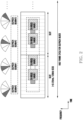
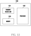
- FIG. 12 is a block diagram of a terminal according to an embodiment of the present disclosure.
- a terminal 1200 may include a transmit/receive unit 1201, a control unit (processor) 1202, and a storage unit (memory) 1203.
- the transmit/receive unit 1201, the control unit 1202, and the storage unit 1203 of the terminal 1200 may operate according to a method and/or embodiments proposed in the present disclosure.
- a component of the terminal 1200 according to an embodiment is not limited to the above-described example.
- the terminal 1200 may include more or fewer components than the above-described components.
- the transmit/receive unit 1201, the control unit 1202, and the storage unit 1203 may be implemented in a form of one chip.
- the transmit/receive unit 1201 may be configured as a transmit unit and a receive unit according to another embodiment.
- the transmit/receive unit 1201 may transmit and receive a signal to and from a base station.
- the signal may include control information and data.
- the transmit/receive unit 1201 may be configured with an RF transmitter that up-converts and amplifies frequency of a transmitted signal, and an RF receiver that amplifies the received signal with low noise and down-converts the frequency.
- the transmit/receive unit 1201 may output a signal by receiving it through a wireless channel to the control unit 1202, and transmit the signal outputted from the control unit 1202 through the wireless channel.
- the control unit 1202 may control a series of processes in which the terminal 1200 may operate according to the above-described embodiment of the present disclosure.
- the control unit 1202 may control a process in which the terminal obtains DL sync for each TX beam of the base station, calculates a DL sync difference value between a serving beam and neighbor beams, and reports this to the base station.
- the control unit 1202 may include at least one processor.
- the control unit 1202 may include a communication processor (CP) that performs control for communication and an application processor (AP) that controls a higher layer such as an application program.
- CP communication processor
- AP application processor
- the storage unit 1203 may store a DL sync difference value between the serving beam and the neighbor beam calculated by the terminal 1200 and/or information related to the DL sync difference, and may have an area for storing data required for controlling the control unit 1202 and data generated when the control unit 1202 controls.
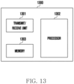
- FIG. 13 is a block diagram of a base station according to an embodiment.
- a base station 1300 may include a transmit/receive unit 1301, a control unit (processor) 1302, and a storage unit (memory) 1303.
- the transmit/receive unit 1301, the control unit 1302, and the storage unit 1303 of the base station 1300 may operate according to a method and/or embodiments proposed in the present disclosure.
- a component of the base station 1300 according to an embodiment is not limited to the above-described example.
- the base station 1300 may include more or fewer components than the above-described components.
- the transmit/receive unit 1301, the control unit 1302, and the storage unit 1303 may be implemented in a form of one chip.
- the transmit/receive unit 1301 may be configured as a transmit unit and a receive unit according to another embodiment.
- the transmit/receive unit 1301 may transmit and receive a signal to and from a terminal.
- the signal may include control information and data.
- the transmit/receive unit 1301 may be configured with an RF transmitter that up-converts and amplifies frequency of a transmitted signal, and an RF receiver that amplifies the received signal with low noise and down-converts the frequency.
- the transmit/receive unit 1301 may output a signal by receiving it through a wireless channel to the control unit 1302, and transmit the signal outputted from the control unit 1302 through the wireless channel.
- the control unit 1302 may control a series of processes so that the base station 1300 may operate according to the above-described embodiment of the present disclosure.
- the controller 1302 may calculate a TA value based on DL sync difference value included in the beam-related reporting received from the terminal according to an embodiment of the present disclosure, and may control to transmit beam change request information including information (e.g., TCI state) on a new beam and the TA value to the terminal.
- the control unit 1302 may include at least one processor.
- the control unit 1302 may include a communication processor (CP) that performs control for communication and an application processor (AP) that controls a higher layer such as an application program.
- CP communication processor
- AP application processor
- the storage unit 1303 may store the DL sync difference value, beam-related reporting information, and the like received from the terminal, and may have an area for storing data required for control of the control unit 1302 and data generated when the control unit 1302 controls.
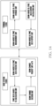
- FIG. 14 is another example of a block diagram of a terminal and a base station according to an embodiment of the present disclosure.
- a terminal 1200 may include a measurement unit that measures DL Sync of different beams, a calculation unit that calculates a DL sync difference between a serving beam and a neighbor beam, a storage unit that stores a DL sync difference value, and a reporting unit that reports DL Sync Delta information to a base station by adding it to the existing beam feedback.
- a measurement unit that measures DL Sync of different beams
- a calculation unit that calculates a DL sync difference between a serving beam and a neighbor beam
- a storage unit that stores a DL sync difference value
- a reporting unit that reports DL Sync Delta information to a base station by adding it to the existing beam feedback.
- the reporting unit may be included in a transmit/receive unit
- the storage unit may be included in a memory
- the measurement unit and the calculation unit may be included in a processor.
- a base station 1300 may include a reception unit that receives the beam feedback transmitted from the terminal, a calculation unit that calculates the Timing Advance based on the received DL Sync Delta, a determination unit that determines whether to change the beam, and a transmission unit that transmits a beam change request by including calculation TA when requesting the beam change when the beam change is determined.
- a reception unit that receives the beam feedback transmitted from the terminal
- a calculation unit that calculates the Timing Advance based on the received DL Sync Delta
- a determination unit determines whether to change the beam
- a transmission unit that transmits a beam change request by including calculation TA when requesting the beam change when the beam change is determined.
- the term ' ⁇ unit' used in the above-described embodiment of the present disclosure refers to software or hardware components such as a field programmable gate array (FPGA) or an application specific integrated circuit (ASIC), and ' ⁇ unit' performs certain roles.
- the ' ⁇ unit' does not mean limited to software or hardware.
- the ' ⁇ unit' may be configured to be in an addressable storage medium or may be configured to reproduce one or more processors. Therefore, as an example, the ' ⁇ unit' includes components such as software components, object-oriented software components, class components, and task components, processes, functions, properties, procedures, sub-routines, segments of program code, drivers, firmware, microcode, circuit, data, database, data structures, tables, arrays, and variables.
- a function provided within the components and the ' ⁇ units' may be combined into a smaller number of components and ' ⁇ units' or further divided into additional components and ' ⁇ units.' Additionally, the components and the ' ⁇ units' may be implemented to reproduce one or more CPUs within a device or a secure multimedia card. In addition, in an embodiment, the ' ⁇ unit' may include one or more processors.
Landscapes
- Engineering & Computer Science (AREA)
- Computer Networks & Wireless Communication (AREA)
- Signal Processing (AREA)
- Quality & Reliability (AREA)
- Physics & Mathematics (AREA)
- Electromagnetism (AREA)
- Mobile Radio Communication Systems (AREA)
Applications Claiming Priority (3)
| Application Number | Priority Date | Filing Date | Title |
|---|---|---|---|
| KR20220002689 | 2022-01-07 | ||
| KR1020220046847A KR20230107081A (ko) | 2022-01-07 | 2022-04-15 | 빔 기반의 상향링크 동기 제어 기법 및 장치 |
| PCT/KR2022/018829 WO2023132477A1 (ko) | 2022-01-07 | 2022-11-25 | 빔 기반의 상향링크 동기 제어 기법 및 장치 |
Publications (2)
| Publication Number | Publication Date |
|---|---|
| EP4440211A1 true EP4440211A1 (de) | 2024-10-02 |
| EP4440211A4 EP4440211A4 (de) | 2025-03-26 |
Family
ID=87073910
Family Applications (1)
| Application Number | Title | Priority Date | Filing Date |
|---|---|---|---|
| EP22919014.5A Pending EP4440211A4 (de) | 2022-01-07 | 2022-11-25 | Verfahren und vorrichtung zur steuerung der aufwärtsstreckensynchronisation auf strahlbasis |
Country Status (3)
| Country | Link |
|---|---|
| US (1) | US20240365261A1 (de) |
| EP (1) | EP4440211A4 (de) |
| WO (1) | WO2023132477A1 (de) |
Family Cites Families (7)
| Publication number | Priority date | Publication date | Assignee | Title |
|---|---|---|---|---|
| US8958412B2 (en) * | 2012-05-11 | 2015-02-17 | Samsung Electronics Co., Ltd. | Methods and apparatus for uplink timing alignment in system with large number of antennas |
| KR102043138B1 (ko) * | 2013-04-19 | 2019-11-11 | 삼성전자주식회사 | 분산 셀 구조의 이동 통신 시스템에서 기지국간 동기화 방법 및 장치 |
| KR20170093720A (ko) * | 2016-02-04 | 2017-08-16 | 주식회사 케이티 | 새로운 프레임 구조를 위한 하향 동기 신호 전송 방법 및 그 장치 |
| KR102503793B1 (ko) * | 2018-04-25 | 2023-02-24 | 한국전자통신연구원 | 무선 mxn 시스템에서 빔 기반 동기신호 전송 및 동기획득 장치 및 방법 |
| CN110662285B (zh) * | 2018-06-29 | 2022-11-08 | 中兴通讯股份有限公司 | 定时调整信息的配置方法及装置 |
| WO2020041757A1 (en) * | 2018-08-23 | 2020-02-27 | Intel Corporation | Uplink timing adjustment with beam switching |
| KR102871531B1 (ko) * | 2019-05-03 | 2025-10-15 | 한국전자통신연구원 | 타이밍 동기 방법 및 이를 위한 장치 |
-
2022
- 2022-11-25 EP EP22919014.5A patent/EP4440211A4/de active Pending
- 2022-11-25 WO PCT/KR2022/018829 patent/WO2023132477A1/ko not_active Ceased
-
2024
- 2024-07-05 US US18/764,859 patent/US20240365261A1/en active Pending
Also Published As
| Publication number | Publication date |
|---|---|
| EP4440211A4 (de) | 2025-03-26 |
| WO2023132477A1 (ko) | 2023-07-13 |
| US20240365261A1 (en) | 2024-10-31 |
Similar Documents
| Publication | Publication Date | Title |
|---|---|---|
| US11832203B2 (en) | Method and apparatus for determining uplink transmission timing | |
| US12368627B2 (en) | Method and apparatus for cell initial access and paging in wireless cellular communication system | |
| US11838943B2 (en) | Method for generating preamble, method for configuring preamble and equipment thereof, random access method, device, user equipment and base station | |
| US11057259B2 (en) | Method and apparatus for indicating initial access subcarrier spacing in wireless cellular communication system | |
| KR102892809B1 (ko) | 무선 통신 시스템에서 harq 피드백 방법 및 장치 | |
| KR102552291B1 (ko) | 무선통신시스템에서 상향링크 전송전력 제어 방법 및 장치 | |
| US11096218B2 (en) | Method, base station apparatus and user equipment for random access | |
| US11902938B2 (en) | Method and apparatus for determining radio link failure | |
| US10278160B2 (en) | Apparatus and method for performing random access in beam-formed system | |
| KR20210001346A (ko) | 무선 통신 시스템에서 랜덤 액세스을 위한 방법 및 장치 | |
| KR102645317B1 (ko) | mmWave 시스템을 위한 beamforming 기반 송수신 동작 방식 및 장치 | |
| US11405090B2 (en) | Method and apparatus for antenna beam tracking in wireless cellular communication system | |
| US10887922B2 (en) | Method for effectively transmitting control message for random access | |
| CN115088377A (zh) | 用于无线通信系统中的随机接入过程的方法和装置 | |
| US12213170B2 (en) | Method and apparatus for performing handover of terminal in wireless communication system | |
| KR20180049751A (ko) | 밀리미터 웨이브 시스템에서 랜덤 액세스를 위한 방법 및 장치 | |
| CN113330804B (zh) | 用于在无线通信系统中释放分配用于随机接入的pusch资源的方法和装置 | |
| KR20200017229A (ko) | 무선 통신 시스템에서 데이터를 송수신하는 방법 및 장치 | |
| KR20230018472A (ko) | 무선 통신 네트워크에서의 참조 시그널링을 위한 방법 및 시스템 | |
| CN118511608A (zh) | 基于波束的上行同步控制方法和设备 | |
| EP4440211A1 (de) | Verfahren und vorrichtung zur steuerung der aufwärtsstreckensynchronisation auf strahlbasis | |
| KR20230107081A (ko) | 빔 기반의 상향링크 동기 제어 기법 및 장치 |
Legal Events
| Date | Code | Title | Description |
|---|---|---|---|
| STAA | Information on the status of an ep patent application or granted ep patent |
Free format text: STATUS: THE INTERNATIONAL PUBLICATION HAS BEEN MADE |
|
| PUAI | Public reference made under article 153(3) epc to a published international application that has entered the european phase |
Free format text: ORIGINAL CODE: 0009012 |
|
| STAA | Information on the status of an ep patent application or granted ep patent |
Free format text: STATUS: REQUEST FOR EXAMINATION WAS MADE |
|
| 17P | Request for examination filed |
Effective date: 20240628 |
|
| AK | Designated contracting states |
Kind code of ref document: A1 Designated state(s): AL AT BE BG CH CY CZ DE DK EE ES FI FR GB GR HR HU IE IS IT LI LT LU LV MC ME MK MT NL NO PL PT RO RS SE SI SK SM TR |
|
| A4 | Supplementary search report drawn up and despatched |
Effective date: 20250221 |
|
| RIC1 | Information provided on ipc code assigned before grant |
Ipc: H04B 7/06 20060101ALI20250218BHEP Ipc: H04W 16/28 20090101ALI20250218BHEP Ipc: H04W 24/10 20090101ALI20250218BHEP Ipc: H04W 56/00 20090101AFI20250218BHEP |
|
| DAV | Request for validation of the european patent (deleted) | ||
| DAX | Request for extension of the european patent (deleted) |