EP4440180A1 - Informationsmeldeverfahren und -vorrichtung, informationskonfigurationsverfahren und -vorrichtung, endgerät und netzwerkseitige vorrichtung - Google Patents
Informationsmeldeverfahren und -vorrichtung, informationskonfigurationsverfahren und -vorrichtung, endgerät und netzwerkseitige vorrichtung Download PDFInfo
- Publication number
- EP4440180A1 EP4440180A1 EP22897719.5A EP22897719A EP4440180A1 EP 4440180 A1 EP4440180 A1 EP 4440180A1 EP 22897719 A EP22897719 A EP 22897719A EP 4440180 A1 EP4440180 A1 EP 4440180A1
- Authority
- EP
- European Patent Office
- Prior art keywords
- terminal
- primary
- network side
- primary terminal
- side device
- Prior art date
- Legal status (The legal status is an assumption and is not a legal conclusion. Google has not performed a legal analysis and makes no representation as to the accuracy of the status listed.)
- Pending
Links
Images


Classifications
-
- H—ELECTRICITY
- H04—ELECTRIC COMMUNICATION TECHNIQUE
- H04W—WIRELESS COMMUNICATION NETWORKS
- H04W28/00—Network traffic management; Network resource management
- H04W28/02—Traffic management, e.g. flow control or congestion control
- H04W28/0278—Traffic management, e.g. flow control or congestion control using buffer status reports
-
- H—ELECTRICITY
- H04—ELECTRIC COMMUNICATION TECHNIQUE
- H04W—WIRELESS COMMUNICATION NETWORKS
- H04W24/00—Supervisory, monitoring or testing arrangements
- H04W24/02—Arrangements for optimising operational condition
-
- H—ELECTRICITY
- H04—ELECTRIC COMMUNICATION TECHNIQUE
- H04W—WIRELESS COMMUNICATION NETWORKS
- H04W24/00—Supervisory, monitoring or testing arrangements
- H04W24/10—Scheduling measurement reports ; Arrangements for measurement reports
Definitions
- This application belongs to the technical field of communications, and particularly relates to an information reporting method and apparatus, a configuration method and apparatus, a terminal and a network side device.
- MAC Medium Access Control
- RLC Radio Link Control
- PDCP Packet Data Convergence Protocol
- BSR Buffer Status Report
- Embodiments of this application provide an information reporting method and apparatus, a configuration method and apparatus, a terminal and a network side device, which can solve the problem of how to report a BSR in a terminal aggregation architecture.
- a first aspect provides an information reporting method, applied to a primary terminal, including:
- a second aspect provides an information reporting apparatus, applied to a secondary terminal, including:
- a third aspect provides a configuration method, applied to a network side device, including:
- a fourth aspect provides an information reporting apparatus, applied to a primary terminal, including:
- a fifth aspect provides an information reporting apparatus, applied to a secondary terminal, including:
- a sixth aspect provides a configuration apparatus, applied to a network side device, including:
- a seventh aspect provides a terminal, including a processor and a memory.
- the memory stores a program or instruction runnable in the processor, and the program or instruction, when executed by the processor, implements steps of the method according to the first aspect, or steps of the method according to the second aspect.
- the terminal is a primary terminal or a secondary terminal, including a processor and a communication interface.
- the primary terminal is capable of co-transmitting data with the secondary terminal.
- the communication interface is configured to receive configuration information from a network side device, and send a BSR to the network side device according to the configuration information.
- a ninth aspect provides a network side device.
- the network side device includes a processor and a memory.
- the memory stores a program or instruction runnable in the processor, and the program or instruction, when executed by the processor, implements steps of the method according to the third aspect.
- a tenth aspect provides a network side device, including a processor and a communication interface.
- the communication interface is configured to send configuration information to a primary terminal and/or a secondary terminal.
- the primary terminal is capable of co-transmitting data with the secondary terminal.
- An eleventh aspect provides a communication system, including: a primary terminal, a secondary terminal and a network side device.
- the primary terminal may be configured to execute steps of the information reporting method according to the first aspect.
- the secondary terminal may be configured to execute steps of the information reporting method according to the second aspect.
- the network side device may be configured to execute steps of the information reporting method according to the third aspect.
- a twelfth aspect provides a readable storage medium, storing a program or instruction therein.
- the program or instruction when executed by the processor, implements steps of the method according to the first aspect, or steps of the method according to the second aspect, or steps of the method according to the third aspect.
- a thirteenth aspect provides a chip, including a processor and a communication interface.
- the communication interface is coupled with the processor.
- the processor is configured to run a program or instruction to implement steps of the method according to the first aspect, or steps of the method according to the second aspect, or steps of the method according to the third aspect.
- a fourteenth aspect provides a computer program/program product.
- the computer program/program product is stored in a storage medium.
- the computer program/program product is executed by at least one processor to implement steps of the method according to the first aspect, or steps of the method according to the second aspect, or steps of the method according to the third aspect.
- a fifteenth aspect provides a communication device, configured to execute steps of the method according to the first aspect, or steps of the method according to the second aspect, or steps of the method according to the third aspect.
- the primary terminal may receive configuration information from the network side device, and send a BSR to the network side device according to the configuration information, and the primary terminal may perform data common transmission with the secondary terminal.
- the BSR reporting manner in the terminal aggregation architecture can be determined, so that the network side device can better perform uplink resource scheduling and transmission of each terminal according to the buffer reporting situation.
- LTE Long Term Evolution
- LTE-A Long Term Evolution-Advanced
- CDMA code division multiple access
- Time Division Multiple Access Time Division Multiple Access
- FDMA frequency division multiple access
- OFDMA Orthogonal Frequency Division Multiple Access
- SC-FDMA single-carrier Frequency Division Multiple Access
- system and “network” in the embodiments of this application are often used interchangeably, and the technologies described may be used not only for the above-mentioned systems and radio technologies, but also for other systems and radio technologies.
- the following description describes a new radio (New Radio, NR) system for exemplary purposes, and NR terminology is used in most of the following descriptions, but these technologies may also be applied to applications other than NR system applications, such as 6 th generation (6 th Generation, 6G) communication systems.
- 6 th generation 6 th Generation
- FIG. 1 shows a block diagram of a wireless communication system applicable to embodiments of this application.
- the wireless communication system includes terminals 11 and a network side device 12.
- the terminal 11 may be a mobile phone, a tablet personal computer (Tablet Personal Computer), a laptop computer (Laptop Computer) or notebook computer, a personal digital assistant (Personal Digital Assistant, PDA), a palm computer, a netbook, an ultra-mobile personal computer (UMPC), a mobile Internet device (Mobile Internet Device, MID), an augmented reality (AR)/virtual reality (VR) device, a robot, a wearable device (Wearable Device), vehicle user equipment (Vehicle User Equipment, VUE), pedestrian user equipment (Pedestrian User Equipment, PUE), a smart home (home devices with a wireless communication function, such as a refrigerator, a television, a washing machine, furniture or the like), a game machine, a personal computer (PC), a teller machine, a self-service machine and other terminal side devices.
- UMPC ultra
- the wearable device includes a smart watch, a smart bracelet, smart headphones, smart glasses, smart jewelry (a smart bangle bracelet, a smart chain bracelet, a smart ring, a smart necklace, a smart bangle anklet, a smart chain anklet, etc.), a smart wristband, smart clothes, etc.
- the network side device 12 may include an access network device or a core network device.
- the access network device 12 may also be called a radio access network device, a radio access network (Radio Access Network, RAN), a radio access network function or a radio access network unit.
- the access network device 12 may include a base station, a wireless local area network (Wireless Local Area Network, WLAN) access point, a WiFi node or the like.
- the base station may be called a node B, an evolved node B (Evolved Node B, eNB), an access point, a base transceiver station (Base Transceiver Station, BTS), a radio base station, a radio transceiver, a basic service set (Basic Service Set, BSS), an extended service set (Extended Service Set, ESS), a home node B, a home evolved node B, a transmitting receiving point (Transmitting Receiving Point, TRP) or some appropriate terms in the art.
- the base station is not limited to a specific technical vocabulary as long as the same technical effect is achieved.
- multi-terminal architecture/terminal aggregation architectures of aggregation/backup/switchover bearers involved mainly refers to user plane (User Plane, UP) protocol stack architectures shown in FIG. 2A to FIG. 2C .
- the UP protocol stack architecture shown in FIG. 2A may also be called a PDCP anchor architecture, and PDCP entities of a primary terminal (P-UE) are respectively associated with RLC entities of the P-UE and a secondary terminal (S-UE).
- the UP protocol stack architecture shown in FIG. 2B may also be called an RLC anchor architecture, and PDCP entities of a P-UE are respectively associated with MAC entities of the P-UE and an S-UE.
- the UP protocol stack architecture shown in FIG. 2C may also be called a MAC anchor architecture, and PDCP entities of a P-UE are respectively associated with physical (Physical, PHY) entities of the P-UE and an S-UE. It can be understood that in the multi-terminal architecture, there is a primary terminal which is associated with at least one secondary terminal, that is, there may be one or more secondary terminals.
- the bearers involved mainly include the following types:
- the bearers involved in 1) and 3) may perform BSR reporting, packetization and sending according to the existing manners.
- This application focuses on the BSR reporting, packetization and sending process related to the new bearer type/aggregation bearer, and the following embodiments will be described in detail mainly by taking the new bearer type as an example.
- the corresponding existing bearer can be superimposed on the new bearer for BSR reporting, packetization and sending according to needs and actual conditions.
- the aggregation bearer in this embodiment of this application may also be called a backup bearer, a switchover bearer, a split bearer, etc., which is not limited herein.
- the multi-terminal bearer aggregation architecture involves in-depth cooperation between multiple terminals, the characteristics of the interfaces between the terminals have important determinants for buffer reporting and data packet organizing of multi-terminal aggregation bearers.
- the interfaces between the terminals may be non-ideal interfaces or ideal interfaces.
- the non-ideal interfaces may be applicable to scenes that do not require high interface characteristics, and may be applicable to all interface types, for example, wired interfaces/wireless interfaces, standardized interfaces/non-standardized interfaces, PC5 interfaces/bluetooth/wifi, etc. may be used between the UEs.
- Non-ideal interfaces have the characteristics that real-time information and data interaction between terminals cannot be achieved, and the general interaction latency is on the order of milliseconds (ms) or sub-ms, for example, 10 ⁇ -2ms to tens of ms.
- data generated by the primary terminal needs to be sent to the secondary terminal in advance, and the secondary terminal performs BSR reporting according to the buffered data volume of the aggregation bearer, requests scheduling to the base station, and organizes the data already in its buffer to be packetized and sent according to the size of scheduling resources.
- Ideal interfaces have the characteristic that the transmission latency between terminals is low enough, for example, less than or much less than the order of ms, so that fast interaction of the status and data can be achieved between terminals and the transmission and scheduling efficiency is higher.
- the interfaces between the terminals are non-ideal interfaces, then the applicable architecture is the PDCP anchor architecture shown in FIG. 2A .
- the interfaces between the terminals are ideal interfaces, any UP protocol stack architecture in FIG. 2A to FIG. 2C may be selected.
- a size of the buffered data volume may be reported to the base station through a BSR process, and the base station performs scheduling according to the size of the buffered data volume and allocates appropriate uplink resources for uplink transmission of the terminals.
- Manners for triggering the BSR may include at least one of:
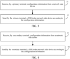
- FIG. 3 is a flowchart of an information reporting method according to embodiments of this application. The method is executed by a primary terminal. As shown in FIG. 3 , the method includes the following steps:
- the primary terminal is capable of co-transmitting data with a secondary terminal. That is, the data of a certain service or the data of the primary terminal may be transmitted together by the primary terminal and the secondary terminal, that is, the data can be jointly transmitted by the primary terminal and the secondary terminal.
- the sending the BSR to the network side device may be referred to as: performing BSR reporting to the network side device.
- the primary terminal may receive configuration information from the network side device, and send a BSR to the network side device according to the configuration information, and the primary terminal may perform data common transmission with the secondary terminal.
- the BSR reporting manner in the terminal aggregation architecture may be determined, so that the network side device can better perform uplink resource scheduling and transmission of each terminal according to the buffer reporting situation.
- the data of a single user is sufficiently and efficiently transmitted by using the links of multiple terminals, so as to enhance the service experience of the user, ensure the quality of service (Quality of Service, QoS) of the service, thereby ensuring the system efficiency while improving the user experience.
- QoS Quality of Service
- the network side device In the interaction between the terminal and the network side device, the network side device is always in the position of the controller and the terminal is in the position of the controlled. Therefore, in different cases, if a unified understanding and unified behaviors between the network side device and the terminal are to be achieved, the network side device needs to send the configuration information to the terminal.
- the configuration information may be used for indicating at least one of the following:
- the network side device and the primary terminal can have the same knowledge of the BSR and data processing manners, and can operate according to a unified BSR reporting manner.
- a UE reporting process may be introduced, and the information reported is, for example, information of interfaces between UEs and/or the preferred operation and processing manner of the UE, so that the base station can decide the appropriate data processing manner.
- the reporting may be performed only by the primary UE.
- the primary UE and the secondary UE may separately perform the BSR reporting process.
- the buffered data volume reported by the primary UE may include the sum of a data volume of a PDCP entity and an RLC entity corresponding to the bearer (the existing bearer type) only at the primary UE, plus a data volume of a PDCP entity corresponding to the split bearer (new bearer type) whose anchor is at the primary UE and a corresponding RLC entity at the primary UE.
- the buffered data volume reported by the secondary UE may include the sum of a data volume of a PDCP entity and an RLC entity corresponding to the bearer (the existing bearer type) only at the secondary UE, plus a data volume of a PDCP entity corresponding to the split bearer (new bearer type) whose anchor is at the primary UE and a corresponding RLC entity at the secondary UE.
- the primary UE reports the BSR corresponding to the split bearer whose anchor is at the primary UE
- the data volume reported may include the sum of the data volume corresponding to the bearer only at the primary UE, plus the data volume of the PDCP entity corresponding to the split bearer whose anchor is at the primary UE and the corresponding RLC entity at the primary UE, and optionally, plus the data volume of the RLC entity at the secondary UE corresponding to the PDCP entity corresponding to the split bearer whose anchor is at the primary UE.
- the secondary UE may or may not report the BS contents corresponding to the new bearer.
- a supplementary BSR corresponding to the split bearer whose anchor is at the primary UE may be reported at the secondary UE, which includes only the data volume of the RLC entity at the secondary UE corresponding to the PDCP entity corresponding to the split bearer whose anchor is at the primary UE.
- the primary UE may organize uplink sending of the data packets of the existing bearer type and/or the new bearer type according to the received uplink grant resources allocated by the base station.
- the secondary UE may organize uplink sending of the data packets of the existing bearer type and/or the new bearer type according to the received uplink grant resources allocated by the base station.
- the secondary UE requests data of the new bearer type from the primary UE according to the received uplink grant resources allocated by the base station, and performs uplink sending according to the data sent by the primary UE.
- the BSR of the primary terminal will be described below on a case-by-case basis in conjunction with the types of the interfaces between the terminals.
- the interfaces between the terminals are non-ideal interfaces, and the PDCP anchor architecture shown in FIG. 2A is adopted.
- the primary terminal may report the BSR using the existing BSR triggering manner, for example, regular event triggering, Padding BSR triggering and/or periodic triggering, according to the configuration of the network side device.
- the buffered data volume in the BSR of the primary terminal may include at least one of:
- the aggregation bearer is a split bearer whose PDCP anchor is at the primary terminal.
- the primary terminal when receiving an uplink resource scheduling grant of the network side device, may packetize the data buffered therein according to the existing logical channel priority rules, and send the data packet obtained by the packetization.
- the primary terminal may send data of the PDCP entity of the aggregation bearer to the secondary terminal to be buffered through the interfaces between the primary and secondary terminals by way of distribution or replication according to a certain strategy or a status feedback or request from the secondary UE.
- the interfaces between the terminals are ideal interfaces, and the PDCP anchor architecture shown in FIG. 2A is adopted. Since the interfaces between the terminals are ideal interfaces, that is, the interaction of information and data between the terminals is fast enough, primary data corresponding to the aggregation bearer may be stored in the primary terminal, and the primary terminal is responsible for primary BSR reporting, that is, the secondary terminal does not need to buffer any RLC SDU/ PDU data to be initially transmitted.
- the primary terminal may report the BSR using the existing BSR triggering manner, for example, regular event triggering, Padding BSR triggering and/or periodic triggering, according to the configuration of the network side device or upon receiving the BSR request of the secondary terminal.
- the existing BSR triggering manner for example, regular event triggering, Padding BSR triggering and/or periodic triggering, according to the configuration of the network side device or upon receiving the BSR request of the secondary terminal.
- the buffered data volume in the BSR of the primary terminal may include at least one of:
- the aggregation bearer is a split bearer whose PDCP anchor is at the primary terminal.
- the distinguishing method may include: the primary terminal sends the first data volume using a target logical channel group (Logical Channel Group, LCG)/specific LCG, or the primary terminal sends the first data volume using a target MAC CE/specific MAC CE.
- LCG Logical Channel Group
- the target LCG/specific LCG may be predefined or configured in the network, and is not used for transmitting the buffered data volumes of the previous two items.
- the target MAC CE/specific MAC CE may be predefined or configured in the network, and is not used for transmitting the buffered data volumes of the previous two items.
- Case II that is, in a case that ideal interfaces and the PDCP anchor architecture are adopted, the BSR form in Case I may be used, but on this basis, the data volume corresponding to the secondary terminal, for example, the first data volume, may also be reported.
- the BSR of the primary terminal may be sent in a case that a BSR request of the secondary terminal is received.
- the BSR request includes the first data volume, and the first data volume is reported by the primary terminal.
- the primary terminal when receiving an uplink resource scheduling grant of the network side device, may packetize the data buffered therein according to the existing logical channel priority rules, and send the data packet obtained by the packetization.
- the primary terminal may monitor a physical downlink control channel (Physical Downlink Control Channel, PDCCH) of the secondary terminal to acquire the size of the uplink grant resources, or the primary terminal may receive a first request from the secondary terminal.
- the first request includes the size of the uplink grant resources.
- the secondary terminal before requesting data from the primary terminal, may subtract the size of resources occupied by the data buffered in the secondary terminal to be transmitted from the size of the total grant resources, or subtract the size of resources of the data buffered in the secondary terminal to be transmitted with higher priority from the total grant resources, and then request the data from the primary terminal according to the size of the remaining resources.
- the secondary terminal before requesting data from the primary terminal, may include complete information (for example, the size of the total grant resources, the data volume buffered in the secondary terminal and the corresponding logical channel/logical channel group/priority information) in the corresponding request and then request the data from the primary terminal, and the primary terminal determines the data volume to be sent to the secondary terminal after a comprehensive consideration, and sends new data to the secondary terminal according to this data volume.
- complete information for example, the size of the total grant resources, the data volume buffered in the secondary terminal and the corresponding logical channel/logical channel group/priority information
- the new data sent by the primary terminal to the secondary terminal can only be in the form of a PDCP PDU or complete RLC SDU.
- the interfaces between the terminals are ideal interfaces, and the RLC entity or layers below adopt the anchor architecture, for example, the anchor architecture shown in FIG. 2B or FIG. 2C .
- the RLC entity must be located at the primary terminal.
- all types of data that need to be transmitted by the secondary terminal in Case II for example, the RLC SDU segment, the RLC retransmitted PDU and the RLC status PDU, may be buffered in the anchor RLC entity of the primary terminal, so the secondary terminal may have no buffered data to be sent.
- the primary terminal may report the BSR using the existing BSR triggering manner, for example, regular event triggering, Padding BSR triggering and/or periodic triggering, according to the configuration of the network side device.
- the buffered data volume in the BSR of the primary terminal may include at least one of:
- the aggregation bearer is a split bearer whose RLC anchor is at the primary terminal.
- the secondary terminal does not have the RLC layer and layers above, and thus, have no demands for BSR reporting.
- the primary terminal when receiving an uplink resource scheduling grant of the network side device, may packetize the data buffered therein according to the existing logical channel priority rules, and send the data packet obtained by the packetization.
- the primary terminal may acquire a size of uplink grant resources allocated by the network side device for the secondary terminal, and send first data buffered and conforming to the size of the uplink grant resources to the secondary terminal, and the secondary terminal may packetize the first data and send the data packet obtained by the packetization.
- the primary terminal may monitor a PDCCH of the secondary terminal to acquire the size of the uplink grant resources, or the primary terminal may receive a first request from the secondary terminal.
- the first request includes the size of the uplink grant resources.
- the first data may include at least one of:
- FIG. 4 is a flowchart of an information reporting method according to embodiments of this application. The method is executed by a secondary terminal. As shown in FIG. 4 , the method includes the following steps:
- the secondary terminal is capable of co-transmitting data with a primary terminal. That is, the data of a certain service or the data of the primary terminal may be transmitted together by the primary terminal and the secondary terminal, that is, the data can be jointly transmitted by the primary terminal and the secondary terminal.
- the sending the BSR to the network side device may be referred to as: performing BSR reporting to the network side device.
- the secondary terminal may receive configuration information from the network side device, and send a BSR to the network side device according to the configuration information, and the secondary terminal may perform data common transmission with the primary terminal.
- the BSR reporting manner in the terminal aggregation architecture can be determined, so that the network side device can better perform uplink resource scheduling and transmission of each terminal according to the buffer reporting situation, thereby ensuring the system efficiency while improving the user experience.
- the configuration information may be used for indicating at least one of the following:
- the network side device and the secondary terminal can have the same knowledge of the BSR and data processing manners, and can operate according to a unified BSR reporting manner.
- the BSR of the secondary terminal will be described below on a case-by-case basis in conjunction with the types of the interfaces between the terminals.
- the interfaces between the terminals are non-ideal interfaces, and the PDCP anchor architecture shown in FIG. 2A is adopted.
- the secondary terminal may report the BSR using the existing BSR triggering manner, for example, regular event triggering, Padding BSR triggering and/or periodic triggering, according to the configuration of the network side device.
- the buffered data volume in the BSR of the secondary terminal may include at least one of:
- the aggregation bearer is a split bearer whose PDCP anchor is at the primary terminal.
- the secondary terminal may acquire uplink grant resources allocated by the network side device for the secondary terminal, packetize buffered data of the secondary terminal according to the size of the uplink grant resources, and send the data packet obtained by the packetization.
- the secondary terminal when receiving an uplink resource scheduling grant of the network side device, may packetize the data buffered therein according to the existing logical channel priority rules, and send the data packet obtained by the packetization.
- the primary terminal may send data of the PDCP entity of the aggregation bearer to the secondary terminal to be buffered through the interfaces between the primary and secondary terminals by way of distribution or replication according to a certain strategy or a status feedback or request from the secondary UE.
- the interfaces between the terminals are ideal interfaces, and the PDCP anchor architecture shown in FIG. 2A is adopted. Since the interfaces between the terminals are ideal interfaces, that is, the interaction of information and data between the terminals is fast enough, primary data corresponding to the aggregation bearer may be stored in the primary terminal, and the primary terminal is responsible for primary BSR reporting, that is, the secondary terminal does not need to buffer any RLC SDU/ PDU data to be initially transmitted.
- the buffered data volume of the secondary terminal may include at least one of:
- the aggregation bearer is a split bearer whose PDCP anchor is at the primary terminal.
- the secondary terminal may use the existing BSR triggering manner or the new BSR triggering manner according to the configuration. For example, once the buffered data volume of the RLC entity of the secondary terminal corresponding to the PDCP entity of the aggregation bearer is not 0, regular BSR or padding BSR may be triggered, or this data volume may be notified to the primary terminal through a request, and the reporting may be performed by the primary terminal.
- the secondary terminal may send a BSR request to the primary terminal.
- the BSR request includes a first data volume and is used for reporting the first data volume by the primary terminal.
- the secondary terminal may not buffer the RLC SDU/PDU to be initially transmitted. However, some data must be located in the to-be-transmitted buffer of the secondary terminal and transmitted through the RLC entity of the secondary terminal.
- the secondary terminal may send second data through an RLC entity thereof.
- the second data includes at least one of:
- the secondary terminal may send a first request to the primary terminal, the first request including a size of the uplink grant resources allocated by the network side device for the secondary terminal; and then receive first data from the primary terminal, packetize the first data, and send the data packet obtained by the packetization.
- the first data is data buffered by the primary terminal and conforming to the size of the uplink grant resources.
- the secondary terminal when receiving an uplink resource scheduling grant of the network side, may request data from the primary terminal according to the existing logical channel priority rules and the size of the grant resources. After receiving new data of the primary terminal, the secondary terminal may packetize the new data sent by the primary terminal and send the data packet.
- the new data sent by the primary terminal to the secondary terminal can only be in the form of a PDCP PDU or a complete RLC SDU.
- the secondary terminal before requesting data from the primary terminal, may subtract the size of resources occupied by the data buffered in the secondary terminal to be transmitted from the size of the total grant resources, or subtract the size of resources of the data buffered in the secondary terminal to be transmitted with higher priority from the total grant resources, and then request the data from the primary terminal according to the size of the remaining resources.
- the secondary terminal before requesting data from the primary terminal, may include complete information (for example, the size of the total grant resources, the data volume buffered in the secondary terminal and the corresponding logical channel/logical channel group/priority information) in the corresponding request and then request the data from the primary terminal, and the primary terminal determines the data volume to be sent to the secondary terminal after a comprehensive consideration, and sends new data to the secondary terminal according to this data volume.
- complete information for example, the size of the total grant resources, the data volume buffered in the secondary terminal and the corresponding logical channel/logical channel group/priority information
- any one of the following items may be executed:
- the interfaces between the terminals are ideal interfaces, and the RLC entity or layers below adopt the anchor architecture, for example, the anchor architecture shown in FIG. 2B or FIG. 2C .
- the secondary terminal does not have the RLC layer and layers above, and thus, have no demands for BSR reporting.
- the secondary terminal may send a first request to the primary terminal, the first request including a size of the uplink grant resources allocated by the network side device for the secondary terminal; and then receive first data from the primary terminal, packetize the first data, and send the data packet obtained by the packetization.
- the first data is data buffered by the primary terminal and conforming to the size of the uplink grant resources.
- the secondary terminal when receiving an uplink resource scheduling grant of the network side, may request data from the primary terminal according to the existing logical channel priority rules and the size of the grant resources. After receiving new data of the primary terminal, the secondary terminal may packetize the new data sent by the primary terminal and send the data packet.
- the new data sent by the primary terminal to the secondary terminal can only be in the form of a PDCP PDU or a complete RLC SDU.
- the first data may include at least one of:
- FIG. 5 is a flowchart of a configuration method according to embodiments of this application.
- the method is executed by a network side device. As shown in FIG. 5 , the method includes the following steps: Step 51: The network side device sends configuration information to a primary terminal and/or a secondary terminal.
- the configuration information may be used for indicating at least one of the following:
- the network side device and the secondary terminal can have the same knowledge of the BSR and data processing manners, and can operate according to a unified BSR reporting manner.
- the network side device may allocate uplink grant resources for the primary terminal and the secondary terminal according to a BSR of the primary terminal.
- the network side device may allocate the uplink grant resources for the primary terminal according to the BSR of the primary terminal, and allocate the uplink grant resources for the secondary terminal according to a BSR of the secondary terminal.
- An execution subject of the information reporting method provided by the embodiments of this application may be an information reporting apparatus.
- the information reporting apparatus provided by the embodiments of this application will be described in an example that the information report apparatus executes the information reporting method.
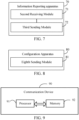
- FIG. 6 is a schematic structural diagram of an information reporting apparatus according to embodiments of this application.
- the apparatus is applied to a primary terminal.
- the information reporting apparatus 60 includes:
- a buffered data volume in the BSR includes at least one of:
- the aggregation bearer is a split bearer whose PDCP anchor is at the primary terminal.
- the buffered data volume in the BSR includes: a first data volume.
- the first data volume is a data volume of an RLC entity located at the secondary terminal corresponding to the PDCP entity of the aggregation bearer.
- the BSR is sent in a case that the primary terminal receives a BSR request of the secondary terminal.
- the BSR request includes the first data volume.
- the first sending module 61 is specifically configured to: send the first data volume using a target LCG, or send the first data volume through a target MAC CE.
- the buffered data volume in the BSR includes at least one of:
- the aggregation bearer is a split bearer whose RLC anchor is at the primary terminal.
- the information reporting apparatus 60 further includes:
- the first acquisition module is specifically configured to:
- the first data includes at least one of:
- the configuration information is used for indicating at least one of the following:
- the information reporting apparatus 60 in this embodiment of this application may be an electronic device, for example, an electronic device with an operating system, or a component in an electronic device, for example, an integrated circuit or a chip.
- the electronic device may be a terminal or other devices other than the terminal.
- the terminal may include, but not limited to, the types of the terminal 11 listed above, and the other devices may be servers, network attached storages (Network Attached Storages, NASs), etc., which is not specifically limited in this embodiment of this application.
- the information reporting apparatus 60 provided by this embodiment of this application can implement processes implemented by the method embodiment of FIG. 3 and achieve the same technical effects. In order to avoid repetition, details will not be described here.
- FIG. 7 is a schematic structural diagram of an information reporting apparatus according to embodiments of this application.
- the apparatus is applied to a secondary terminal.
- the information reporting apparatus 70 includes:
- the BSR includes: a first data volume.
- the first data volume is a data volume of an RLC entity located at the secondary terminal corresponding to a PDCP entity of an aggregation bearer.
- the aggregation bearer is a split bearer whose PDCP anchor is at the primary terminal.
- the information reporting apparatus 70 further includes:
- the information reporting apparatus 70 further includes: a fifth sending module, configured to send a BSR request to the primary terminal, the BSR request including a first data volume and being used for reporting the first data volume by the primary terminal.
- a fifth sending module configured to send a BSR request to the primary terminal, the BSR request including a first data volume and being used for reporting the first data volume by the primary terminal.
- the first data volume is a data volume of an RLC entity located at the secondary terminal corresponding to a PDCP entity of an aggregation bearer.
- the aggregation bearer is a split bearer whose PDCP anchor is at the primary terminal.
- the information reporting apparatus 70 further includes: a sixth sending module, configured to send second data through an RLC entity of the secondary terminal.
- the second data includes at least one of:
- the information reporting apparatus 70 further includes:
- the seventh sending module is further configured to: packetize the first data, and send the data packet obtained by the packetization, the first data being data buffered by the primary terminal and conforming to the size of the uplink grant resources.
- the first data includes at least one of:
- the configuration information is used for indicating at least one of the following:
- the information reporting apparatus 70 in this embodiment of this application may be an electronic device, for example, an electronic device with an operating system, or a component in an electronic device, for example, an integrated circuit or a chip.
- the electronic device may be a terminal or other devices other than the terminal.
- the terminal may include, but not limited to, the types of the terminal 11 listed above, and the other devices may be servers, network attached storages (Network Attached Storages, NASs), etc., which is not specifically limited in this embodiment of this application.
- the information reporting apparatus 70 provided by this embodiment of this application can implement processes implemented by the method embodiment of FIG. 4 and achieve the same technical effects. In order to avoid repetition, details will not be described here.
- An execution subject of the configuration method provided by the embodiments of this application may be a configuration apparatus.
- the configuration apparatus provided by the embodiments of this application will be described in an example that the configuration apparatus executes the configuration method.
- FIG. 8 is a schematic structural diagram of a configuration apparatus according to embodiments of this application.
- the apparatus is applied to a network side device.
- the configuration apparatus 80 includes:
- an eighth sending module 81 configured to send configuration information to a primary terminal and/or a secondary terminal.
- the primary terminal is capable of co-transmitting data with the secondary terminal; and the configuration information is used for indicating at least one of the following:
- the configuration apparatus 80 further includes: an allocation module, configured to allocate uplink grant resources for the primary terminal and the secondary terminal according to a BSR of the primary terminal; or allocate the uplink grant resources for the primary terminal according to the BSR of the primary terminal, and allocate the uplink grant resources for the secondary terminal according to a BSR of the secondary terminal.
- an allocation module configured to allocate uplink grant resources for the primary terminal and the secondary terminal according to a BSR of the primary terminal; or allocate the uplink grant resources for the primary terminal according to the BSR of the primary terminal, and allocate the uplink grant resources for the secondary terminal according to a BSR of the secondary terminal.
- the configuration apparatus 80 provided by this embodiment of this application can implement processes implemented by the method embodiment of FIG. 5 and achieve the same technical effects. In order to avoid repetition, details will not be described here.
- an embodiment of this application further provides a communication device 90, including a processor 91 and a memory 92.
- the memory 92 stores a program or instruction runnable in the processor 91.
- the program or instruction when executed by the processor 91, implements steps of the above information reporting method embodiment and can achieve the same technical effects.
- the communication device 90 is a network side device
- the program or instruction when executed by the processor 91, implements steps of the above configuration method embodiment and can achieve the same technical effects. In order to avoid repetition, details will not be described here.
- An embodiment of this application further provides a terminal, including a processor and a communication interface.
- the communication interface is configured to receive configuration information from a network side device, and send a BSR to the network side device according to the configuration information.
- the terminal in a case that the terminal is a primary terminal, the terminal embodiment corresponds to the above method embodiment of the primary terminal side, and all implementation processes and implementations of the above method embodiment are applicable to the terminal embodiment and can achieve the same technical effects.
- the terminal in a case that the terminal is a secondary terminal, the terminal embodiment corresponds to the above method embodiment of the secondary terminal side, and all implementation processes and implementations of the above method embodiment are applicable to the terminal embodiment and can achieve the same technical effects. In order to avoid repetition, details will not be described here.
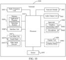
- FIG. 10 is a schematic diagram of a hardware structure of a terminal according to an embodiment of this application.
- the terminal 1000 includes, but not limited to, at least part of a radio frequency unit 1001, a network module 1002, an audio output unit 1003, an input unit 1004, a sensor 1005, a display unit 1006, a user input unit 1007, an interface unit 1008, a memory 1009 and a processor 1010.
- the terminal 1000 may further include a power supply (such as a battery) for supplying power to the components.
- a power supply such as a battery
- the power supply may be logically connected to the processor 1010 through a power management system, thereby implementing functions such as charging, discharging, and power consumption management by using the power management system.
- the terminal structure shown in FIG. 10 does not constitute a limitation to the terminal, and the terminal may include more or fewer components than shown, or combine some components, or have different component arrangements, which will not be described in detail.
- the input unit 1004 may include a graphics processing unit (Graphics Processing Unit, GPU) 10041 and a microphone 10042.
- the graphics processing unit 10041 processes image data of a static picture or a video that is obtained by an image acquisition apparatus (such as a camera) in a video acquisition mode or an image acquisition mode.
- the display unit 1006 may include a display panel 10061.
- the display panel 10061 may be configured in the form of a liquid crystal display (LCD), an organic light-emitting diode, or the like.
- the user input unit 1007 includes a touch panel 10071 and at least one of other input devices 10072.
- the touch panel 10071 is also called a touch screen.
- the touch panel 10071 may include two parts: a touch detection apparatus and a touch controller.
- the other input devices 10072 may include, but not limited to, a physical keyboard, a functional key (such as a volume control key or a switch key), a track ball, a mouse and a joystick, which will not described herein in detail.
- the radio frequency unit 1001 after receiving downlink data from the network side device, may transmit the downlink data to the processor 1010 for processing. In addition, the radio frequency unit 1001 may send uplink data to the network side device.
- the radio frequency unit 1001 includes, but is not limited to, an antenna, an amplifier, a transceiver, a coupler, a low noise amplifier, a duplexer, and the like.
- the memory 1009 is configured to store a software program or instruction and various data.
- the memory 1009 may mainly include a first storage area for storing the program or instruction and a second storage area for storing data.
- the first storage area may store an operating system, an application program or instruction required by at least one function (for example, a sound playback function and an image display function), and the like.
- the memory 1009 may include a volatile memory or a non-volatile memory, or the memory 1009 may include both a volatile memory and a non-volatile memory.
- the non-volatile memory may be a read-only memory (Read-Only Memory, ROM), a programmable ROM (Programmable ROM, PROM), an erasable PROM (Erasable PROM, EPROM), an electrically EPROM (Electrically EEPROM) or a flash memory.
- ROM Read-Only Memory
- PROM programmable ROM
- PROM erasable PROM
- EPROM electrically EPROM
- EEPROM Electrically EEPROM
- the volatile memory may be a random access memory (Random Access Memory, RAM), a static RAM (Static RAM, SRAM), a dynamic RAM (Dynamic RAM, DRAM), a synchronous DRAM (Synchronous DRAM, SDRAM), a double data rate SDRAM (Double Data Rate SDRAM, DDRSDRAM), an enhanced SDRAM (Enhanced SDRAM, ESDRAM), a synch link DRAM (Synch link DRAM, SLDRAM) and a direct rambus RAM (Direct Rambus RAM, DRRAM).
- RAM Random Access Memory
- SRAM static RAM
- DRAM dynamic RAM
- DRAM synchronous DRAM
- SDRAM Double data rate SDRAM
- ESDRAM enhanced SDRAM
- Enhanced SDRAM Enhanced SDRAM
- SLDRAM synch link DRAM
- Direct Rambus RAM Direct Rambus RAM
- the processor 1010 may include one or more processing units.
- the processor 1010 integrates an application processor and a modem processor.
- the application processor mainly processes operations related to the operating system, the user interface and application programs, and the modem processor, such as a baseband processor, mainly processes wireless communication signals. It can be understood that the foregoing modem processor may not be integrated into the processor 1010.
- the terminal 1000 may be a primary terminal or a secondary terminal, and the radio frequency unit 1001 is configured to receive configuration information from a network side device and send a BSR to the network side device according to the configuration information.
- the terminal 1000 is a primary terminal
- the terminal embodiment corresponds to the above method embodiment of the primary terminal side
- all implementation processes and implementations of the above method embodiment are applicable to the terminal embodiment and can achieve the same technical effects.
- the terminal embodiment corresponds to the above method embodiment of the secondary terminal side, and all implementation processes and implementations of the above method embodiment are applicable to the terminal embodiment and can achieve the same technical effects. In order to avoid repetition, details will not be described here.
- An embodiment of this application further provides a network side device, including a processor and a communication interface.
- the communication interface is configured to send configuration information to a primary terminal and/or a secondary terminal.
- the network side device embodiment corresponds to the above method embodiment of the network side device, and all implementation processes and implementations of the above method embodiment are applicable to the network side device embodiment and can achieve the same technical effects.
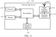
- the network side device 110 includes: an antenna 111, a radio frequency apparatus 112, a baseband apparatus 113, a processor 114 and a memory 115.
- the antenna 111 is connected with the radio frequency apparatus 112.
- the radio frequency apparatus 112 receives information through the antenna 111, and sends the received information to the baseband apparatus 113 for processing.
- the baseband apparatus 113 processes information to be sent, and sends the information to the radio frequency apparatus 112, and the radio frequency apparatus 112 processes the received information and sends out the processed information through the antenna 111.
- the method executed by the network side device in the above embodiment can be implemented in the baseband apparatus 113.
- the baseband apparatus 113 includes a baseband processor.
- the baseband apparatus 113 may include, for example, at least one baseband board.
- the baseband board is provided with a plurality of chips. As shown in FIG. 11 , one of the chips is, for example, the baseband processor, which is connected to the memory 115 through a bus interface so as to invoke a program in the memory 115 to execute network device operations shown in the above method embodiment.
- the network side device may further include a network interface 116, which is, for example, a common public radio interface (CPRI).
- a network interface 116 which is, for example, a common public radio interface (CPRI).
- CPRI common public radio interface
- the network side device 110 in this embodiment of this application further includes: an instruction or program stored in the memory 115 and runnable in the processor 114.
- the processor 114 invokes the instruction or program in the memory 115 to execute methods executed by various modules shown in FIG. 8 and achieve the same technical effects. In order to avoid repetition, details will not be repeated here.
- An embodiment of this application further provides a readable storage medium, which may be non-volatile or volatile.
- the readable storage medium stores a program or instruction therein.
- the program or instruction when executed by a processor, implements processes of the above information reporting method embodiment, or implements processes of the above configuration method embodiment, and can achieve the same technical effects. In order to avoid repetition, details will not be repeated here.
- the processor is the processor in the terminal in the above embodiment.
- the readable storage medium includes a computer-readable storage medium, such as computer read-only memory (ROM), a random access memory (RAM), a magnetic disk, an optical disk or the like.
- An embodiment of this application further provides a chip, including a processor and a communication interface.
- the communication interface is coupled with the processor.
- the processor is configured to run a program or instruction to implement processes of the above information reporting method embodiment or processes of the above configuration method embodiment and can achieve the same technical effects. In order to avoid repetition, details will not be described here.
- the chip mentioned in this embodiment of this application may also be called a system on chip, a system chip, a chip system, a system on a chip or the like.
- An embodiment of this application further provides a computer program/program product.
- the computer program/program product is stored in a storage medium.
- the computer program/program product is executed by at least one processor to implement processes of the above information reporting method embodiment or processes of the above configuration method embodiment and can achieve the same technical effects. In order to avoid repetition, details will not be described here.
- An embodiment of this application further provides a communication system, including: a primary terminal, a secondary terminal and a network side device.
- the primary terminal may be configured to execute steps of the information reporting method of FIG. 3 .
- the secondary terminal may be configured to execute steps of the information reporting method of FIG. 4
- the network side device may be configured to execute steps of the configuration method of FIG. 5 .
- the methods according to the above embodiments can be implemented by means of software plus a necessary general hardware platform, and of course, they can also be implemented by hardware, but in many cases the former is a better implementation.
- the technical solution of this application essentially or for the part that contributes to the related art can be embodied in the form of a software product, and the computer software product is stored in a storage medium (such as an ROM/RAM, a magnetic disk or an optical disk) and includes several instructions to enable a terminal facility (which may be a mobile phone, a computer, a server, an air conditioner, a network device or the like) to execute the method described in the embodiments of this application.
Landscapes
- Engineering & Computer Science (AREA)
- Computer Networks & Wireless Communication (AREA)
- Signal Processing (AREA)
- Mobile Radio Communication Systems (AREA)
Applications Claiming Priority (2)
| Application Number | Priority Date | Filing Date | Title |
|---|---|---|---|
| CN202111405894.9A CN116170818A (zh) | 2021-11-24 | 2021-11-24 | 信息上报方法、配置方法、装置、终端及网络侧设备 |
| PCT/CN2022/132860 WO2023093636A1 (zh) | 2021-11-24 | 2022-11-18 | 信息上报方法、配置方法、装置、终端及网络侧设备 |
Publications (2)
| Publication Number | Publication Date |
|---|---|
| EP4440180A1 true EP4440180A1 (de) | 2024-10-02 |
| EP4440180A4 EP4440180A4 (de) | 2025-03-05 |
Family
ID=86418662
Family Applications (1)
| Application Number | Title | Priority Date | Filing Date |
|---|---|---|---|
| EP22897719.5A Pending EP4440180A4 (de) | 2021-11-24 | 2022-11-18 | Informationsmeldeverfahren und -vorrichtung, informationskonfigurationsverfahren und -vorrichtung, endgerät und netzwerkseitige vorrichtung |
Country Status (4)
| Country | Link |
|---|---|
| US (1) | US20240314626A1 (de) |
| EP (1) | EP4440180A4 (de) |
| CN (1) | CN116170818A (de) |
| WO (1) | WO2023093636A1 (de) |
Families Citing this family (4)
| Publication number | Priority date | Publication date | Assignee | Title |
|---|---|---|---|---|
| CN115278546B (zh) * | 2021-04-30 | 2025-02-18 | 维沃移动通信有限公司 | 数据传输方法、相关设备及可读存储介质 |
| CN118316577A (zh) * | 2023-01-06 | 2024-07-09 | 中兴通讯股份有限公司 | 一种通信方法以及计算机可读存储介质 |
| KR20250046998A (ko) * | 2023-09-27 | 2025-04-03 | 삼성전자주식회사 | 무선 통신 시스템에서 지연 상태 보고 취소 방법 및 장치 |
| CN120980617A (zh) * | 2024-05-15 | 2025-11-18 | 维沃移动通信有限公司 | 信息传输方法、终端及网络侧设备 |
Family Cites Families (9)
| Publication number | Priority date | Publication date | Assignee | Title |
|---|---|---|---|---|
| EP2875593B1 (de) * | 2012-07-20 | 2020-07-01 | LG Electronics Inc. | Verfahren und vorrichtung zur übertragung von vorrichtung-zu-vorrichtung-informationen in drahtlosem kommunikationssystem |
| US9635655B2 (en) * | 2014-02-24 | 2017-04-25 | Intel Corporation | Enhancement to the buffer status report for coordinated uplink grant allocation in dual connectivity in an LTE network |
| EP3240354A1 (de) * | 2016-04-27 | 2017-11-01 | ASUSTek Computer Inc. | Verfahren und vorrichtung zur verbesserung der uplink-übertragung in einem drahtloskommunikationssystem |
| CN109716838B (zh) * | 2016-09-30 | 2021-11-09 | 华为技术有限公司 | 一种资源请求方法、设备及系统 |
| CN110234114B (zh) * | 2019-04-23 | 2022-04-05 | 中国移动通信集团内蒙古有限公司 | 数据传输方法、装置、设备、介质和系统 |
| CN112788655B (zh) * | 2019-11-08 | 2022-07-29 | 华为技术有限公司 | 一种侧行链路信道状态信息报告的发送方法、装置及系统 |
| CN114731684A (zh) * | 2019-12-31 | 2022-07-08 | 华为技术有限公司 | 数据传输方法及装置 |
| CN113301604B (zh) * | 2020-02-24 | 2023-04-07 | 维沃移动通信有限公司 | 缓存状态上报方法、中继终端设备及计算机可读存储介质 |
| US11622409B2 (en) * | 2020-03-10 | 2023-04-04 | Qualcomm Incorporated | User equipment relay procedure |
-
2021
- 2021-11-24 CN CN202111405894.9A patent/CN116170818A/zh active Pending
-
2022
- 2022-11-18 EP EP22897719.5A patent/EP4440180A4/de active Pending
- 2022-11-18 WO PCT/CN2022/132860 patent/WO2023093636A1/zh not_active Ceased
-
2024
- 2024-05-22 US US18/671,558 patent/US20240314626A1/en active Pending
Also Published As
| Publication number | Publication date |
|---|---|
| EP4440180A4 (de) | 2025-03-05 |
| CN116170818A (zh) | 2023-05-26 |
| US20240314626A1 (en) | 2024-09-19 |
| WO2023093636A1 (zh) | 2023-06-01 |
Similar Documents
| Publication | Publication Date | Title |
|---|---|---|
| EP4440180A1 (de) | Informationsmeldeverfahren und -vorrichtung, informationskonfigurationsverfahren und -vorrichtung, endgerät und netzwerkseitige vorrichtung | |
| US12520306B2 (en) | Uplink channel transmission method and apparatus, and terminal | |
| CN115190533B (zh) | 传输处理方法、装置及通信设备 | |
| US20250063566A1 (en) | Information reporting method and apparatus, communication device, and storage medium | |
| EP4422105A1 (de) | Datenablösungsverfahren und -vorrichtung, endgerät und netzwerkseitige vorrichtung | |
| US20240214125A1 (en) | Feedback method, related device, and readable storage medium | |
| US20250324427A1 (en) | Indication method, device, and readable storage medium | |
| US20240306039A1 (en) | Data transmission method, configuration method, apparatus, terminal, and network-side device | |
| CN113965998A (zh) | 上行传输方法、装置及相关设备 | |
| US20260089551A1 (en) | Format Determining Method, User Equipment (UE), and Non-Transitory Readable Storage Medium | |
| CN115333690A (zh) | 信息传输方法、装置、终端及网络侧设备 | |
| CN115175332B (zh) | 上行信道传输方法、装置、终端及网络侧设备 | |
| CN118158819A (zh) | 资源分配方法、装置、终端及网络侧设备 | |
| CN118283821A (zh) | 指示方法、设备及可读存储介质 | |
| US20240080135A1 (en) | Pusch repetition method and device | |
| US20250175851A1 (en) | Data processing method, terminal, and network-side device | |
| CN115604684B (zh) | 信息传输方法、装置及存储介质 | |
| CN118283762A (zh) | 上行功率分配方法、装置、通信设备及存储介质 | |
| CN118944823A (zh) | 上行传输方法、装置及终端 | |
| CN116963170A (zh) | 缓存报告bsr汇报方法、终端及网络侧设备 | |
| WO2026021292A1 (zh) | Lcp处理方法、传输方法、装置、终端及网络侧设备 | |
| CN118283801A (zh) | 资源使用信息上报方法、装置、终端及网络侧设备 | |
| CN118250669A (zh) | 传输方法、装置及终端 | |
| WO2024140635A1 (zh) | 功率分配方法、设备及可读存储介质 | |
| CN121418050A (zh) | 数据处理方法、装置、终端及网络侧设备 |
Legal Events
| Date | Code | Title | Description |
|---|---|---|---|
| STAA | Information on the status of an ep patent application or granted ep patent |
Free format text: STATUS: THE INTERNATIONAL PUBLICATION HAS BEEN MADE |
|
| PUAI | Public reference made under article 153(3) epc to a published international application that has entered the european phase |
Free format text: ORIGINAL CODE: 0009012 |
|
| STAA | Information on the status of an ep patent application or granted ep patent |
Free format text: STATUS: REQUEST FOR EXAMINATION WAS MADE |
|
| 17P | Request for examination filed |
Effective date: 20240430 |
|
| AK | Designated contracting states |
Kind code of ref document: A1 Designated state(s): AL AT BE BG CH CY CZ DE DK EE ES FI FR GB GR HR HU IE IS IT LI LT LU LV MC ME MK MT NL NO PL PT RO RS SE SI SK SM TR |
|
| A4 | Supplementary search report drawn up and despatched |
Effective date: 20250204 |
|
| DAV | Request for validation of the european patent (deleted) | ||
| DAX | Request for extension of the european patent (deleted) | ||
| RIC1 | Information provided on ipc code assigned before grant |
Ipc: H04W 28/02 20090101ALI20250129BHEP Ipc: H04W 24/02 20090101AFI20250129BHEP |