EP4440004A1 - Optical communication device, optical communication system, and optical communication method - Google Patents
Optical communication device, optical communication system, and optical communication method Download PDFInfo
- Publication number
- EP4440004A1 EP4440004A1 EP21965598.2A EP21965598A EP4440004A1 EP 4440004 A1 EP4440004 A1 EP 4440004A1 EP 21965598 A EP21965598 A EP 21965598A EP 4440004 A1 EP4440004 A1 EP 4440004A1
- Authority
- EP
- European Patent Office
- Prior art keywords
- optical
- port
- uplink
- downlink
- subscriber device
- Prior art date
- Legal status (The legal status is an assumption and is not a legal conclusion. Google has not performed a legal analysis and makes no representation as to the accuracy of the status listed.)
- Pending
Links
Images



Classifications
-
- H—ELECTRICITY
- H04—ELECTRIC COMMUNICATION TECHNIQUE
- H04J—MULTIPLEX COMMUNICATION
- H04J14/00—Optical multiplex systems
- H04J14/02—Wavelength-division multiplex systems
- H04J14/0227—Operation, administration, maintenance or provisioning [OAMP] of WDM networks, e.g. media access, routing or wavelength allocation
- H04J14/0254—Optical medium access
- H04J14/0256—Optical medium access at the optical channel layer
-
- H—ELECTRICITY
- H04—ELECTRIC COMMUNICATION TECHNIQUE
- H04B—TRANSMISSION
- H04B10/00—Transmission systems employing electromagnetic waves other than radio-waves, e.g. infrared, visible or ultraviolet light, or employing corpuscular radiation, e.g. quantum communication
- H04B10/27—Arrangements for networking
-
- H—ELECTRICITY
- H04—ELECTRIC COMMUNICATION TECHNIQUE
- H04J—MULTIPLEX COMMUNICATION
- H04J14/00—Optical multiplex systems
- H04J14/02—Wavelength-division multiplex systems
- H04J14/0201—Add-and-drop multiplexing
- H04J14/0215—Architecture aspects
- H04J14/0216—Bidirectional architectures
-
- H—ELECTRICITY
- H04—ELECTRIC COMMUNICATION TECHNIQUE
- H04Q—SELECTING
- H04Q11/00—Selecting arrangements for multiplex systems
- H04Q11/0001—Selecting arrangements for multiplex systems using optical switching
- H04Q11/0005—Switch and router aspects
-
- H—ELECTRICITY
- H04—ELECTRIC COMMUNICATION TECHNIQUE
- H04Q—SELECTING
- H04Q11/00—Selecting arrangements for multiplex systems
- H04Q11/0001—Selecting arrangements for multiplex systems using optical switching
- H04Q11/0005—Switch and router aspects
- H04Q2011/0007—Construction
- H04Q2011/0016—Construction using wavelength multiplexing or demultiplexing
-
- H—ELECTRICITY
- H04—ELECTRIC COMMUNICATION TECHNIQUE
- H04Q—SELECTING
- H04Q11/00—Selecting arrangements for multiplex systems
- H04Q11/0001—Selecting arrangements for multiplex systems using optical switching
- H04Q11/0005—Switch and router aspects
- H04Q2011/0037—Operation
- H04Q2011/005—Arbitration and scheduling
Definitions
- the present invention relates to an optical communication device, an optical communication system, and an optical communication method.
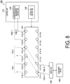
- FIG. 8 illustrates a configuration example of an optical communication system 100 including a conventional optical communication device.
- the optical communication system 100 includes an optical SW 110 and a control unit 115 forming the optical communication device.
- a WDM filter 140 and the control unit 115 are connected to the optical SW 110.
- the optical SW 110 is connected to a plurality of optical transmission lines and outputs an optical signal input from any of the optical transmission lines to another optical transmission line.
- the optical SW 110 of Fig. 8 includes ports 111-1 to 111-6 and ports 112-1 to 112-6.
- the optical SW 110 and the WDM filter 140 are connected by a duplex optical transmission line.
- the port 111-1 of the optical SW 110 and the WDM filter 140 are connected via an optical transmission line 135-1
- the port 111-2 of the optical SW 110 and the WDM filter 140 are connected via an optical transmission line 135-2.
- the optical SW 110 and the control unit 115 are connected by a duplex optical transmission line.
- the port 112-5 of the optical SW 110 and the control unit 115 are connected via an optical transmission line 136-1
- the port 112-6 of the optical SW 110 and the control unit 115 are connected via an optical transmission line 136-2.
- the control unit 115 includes a subscriber device management control unit 120 and an optical SW control unit 130.
- the subscriber device management control unit 120 allocates a wavelength to a subscriber device 105.
- the optical SW control unit 130 switches the path of the optical SW 110.
- the uplink and the downlink are often set to simplex transmission with different wavelengths, but in the relay, the same wavelength is often used with separate uplink and downlink optical transmission lines.
- the simplex subscriber device 105 is transmitted by duplex relay, and the optical signal is converted into duplex by the WDM filter 140. Since the wavelengths are different between the uplink and the downlink, the uplink and the downlink can be separated by changing the pass wavelength band of each port of the WDM filter.
- arrayed waveguide grating may be used to multiplex optical signals transmitted from a plurality of subscriber devices. Since the wavelength that can be accommodated for each port is fixed in the AWG, it is necessary to separate the uplink and the downlink once by the WDM filter 140 and connect to the AWG installed between the optical SW 110 and the optical transmission line through separate ports as in the configuration illustrated in Fig. 8 .
- the uplink port can be identified by presence or absence of optical power by the control signal, but the downlink port corresponding to the subscriber device 105 cannot be found without prior information. Therefore, it is necessary to determine in advance where to set the downlink port with respect to the uplink port of a certain subscriber device 105. For example, it is necessary to determine in advance by a rule such as arranging the uplink and the downlink next to each other.
- Patent Literature 1 WO 2021/131202 A
- An optical transceiver included in the subscriber device 105 is desirably a wavelength-tunable optical transmitter/receiver, and in that case, communication can be performed at an arbitrary wavelength.
- the available wavelength range is limited due to the pass band of the WDM filter 140.
- the uplink and the downlink are selected from among them.
- the pass band of the port of the WDM filter 140 connected to a port 111-1 of the optical SW 110 is set to the 1st to 44th wavelengths and the pass band of the port of the WDM filter 140 connected to a port 111-2 of the optical SW 110 is set to the 45th to 88th wavelengths.
- the wavelength range that can be used in the uplink or the downlink is halved.
- the subscriber device 105 performs communication using a wavelength not used in other communication including the relay section, narrowing the usable wavelength range leads to loss of communication opportunities.
- an object of the present invention is to provide a technique capable of curbing the restriction on usable uplink and downlink wavelength ranges.
- One aspect of the present invention is an optical communication device including an optical switch that is connected to a plurality of optical transmission lines and outputs an optical signal input from any of the optical transmission lines to another optical transmission line, and a transfer unit configured to convert simplex transmission into duplex transmission or converts duplex transmission into simplex transmission between a subscriber device and the optical switch or between a first port of the optical switch to which the subscriber device is directly or indirectly connected and a second port opposite to the first port, and transfers the optical signal so as not to cause interference between uplink and downlink.
- One aspect of the present invention is an optical communication system including: an optical switch that is connected to a plurality of optical transmission lines and outputs an optical signal input from any of the optical transmission lines to another optical transmission line; a transfer unit configured to convert simplex transmission into duplex transmission or converts duplex transmission into simplex transmission by multiplexing or demultiplexing an input optical signal between a subscriber device and the optical switch, and transfers the optical signal so as not to cause interference between uplink and downlink; an uplink/downlink determination unit configured to determine an uplink port and a downlink port among a plurality of ports included in the transfer unit on the basis of information on wavelengths used for the uplink and the downlink allocated to the subscriber device; and an optical switch control unit configured to control connection between ports of the optical switch according to a determination result of the uplink/downlink determination unit.
- One aspect of the present invention is an optical communication method including an optical switch connected to a plurality of optical transmission lines outputting an optical signal input from any of the optical transmission lines to another optical transmission line, and converting simplex transmission into duplex transmission or converting duplex transmission into simplex transmission between a subscriber device and the optical switch or between a first port of the optical switch to which the subscriber device is directly or indirectly connected and a second port opposite to the first port, and transferring the optical signal so as not to cause interference between uplink and downlink.
- One aspect of the present invention is an optical communication method including: an optical switch connected to a plurality of optical transmission lines outputting an optical signal input from any of the optical transmission lines to another optical transmission line; a transfer unit converting simplex transmission into duplex transmission or converting duplex transmission into simplex transmission by multiplexing or demultiplexing an input optical signal between a subscriber device and the optical switch, and transferring the optical signal so as not to cause interference between uplink and downlink; determining an uplink port and a downlink port among a plurality of ports included in the transfer unit on the basis of information on wavelengths used for the uplink and the downlink allocated to the subscriber device; and controlling connection between ports of the optical switch according to a determination result.
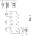
- Fig. 1 is a diagram illustrating a configuration example of an optical communication system 1 according to a first embodiment.
- the optical communication system 1 includes one or more subscriber devices 10, a circulator 20, an optical SW 30, and a control unit 40.
- the subscriber device 10 and the circulator 20, the circulator 20 and the optical SW 30, and the optical SW 30 and the control unit 40 are connected by using an optical transmission line.
- the optical transmission line is, for example, an optical fiber.
- the circulator 20 and the optical SW 30 are examples of functional units forming the optical communication device.
- the subscriber device 10 includes an optical transceiver.
- the optical transceiver is a wavelength-tunable optical transmitter/receiver. Therefore, the subscriber device 10 can perform communication using an arbitrary wavelength.
- the wavelength used for communication by the subscriber device 10 is allocated by the control unit 40.
- the optical transceiver may be an optical transceiver having an auxiliary management and control channel (AMCC) function. In this case, the wavelength used by the subscriber device 10 is controlled via a control signal superimposed by the AMCC.
- the subscriber device 10 is, for example, an optical network unit (ONU) installed in a subscriber's home.
- ONU optical network unit
- the circulator 20 has at least three or more ports. In the following description, it is assumed that the circulator 20 has three ports (for example, first port 21, second port 22, and third port 23).
- the first port 21 of the circulator 20 is connected to the subscriber device 10 via an optical transmission line.
- the second port 22 of the circulator 20 is connected to the optical SW 30 via an optical transmission line 50-1.
- the third port 23 of the circulator 20 is connected to the optical SW 30 via an optical transmission line 50-2.
- An optical signal input to the first port 21 is output from the second port 22.
- An optical signal input to the second port 22 is output from the third port 23.
- An optical signal input to the third port 23 is output from the first port 21.
- the circulator 20 has directivity and port selectivity, but no wavelength selectivity. Therefore, an optical signal output from the subscriber device 10 can be output to the optical SW 30 regardless of the wavelength of the optical signal. Further, the circulator 20 can transfer an optical signal transferred from the optical SW 30 to the subscriber device 10 regardless of the wavelength of the optical signal.
- the circulator 20 is one aspect of a transfer unit.
- the optical SW 30 is an optical switch having M (M is integer of two or more) ports 31 and N (N is integer of two or more) ports 32. In the embodiment, the numbers of M and N are assumed to be six. An optical signal input to a certain port of the optical SW 30 is output from another port. For example, an optical signal input to the port 31 of the optical SW 30 is output from the port 32. In the optical SW 30, a connection relationship between the port 31 and the port 32 is set under the control of the control unit 40.
- the second port 22 of the circulator 20 is connected to a port 31-1 of the optical SW 30 via the optical transmission line 50-1
- the third port 23 of the circulator 20 is connected to a port 31-2 of the optical SW 30 via the optical transmission line 50-2
- the control unit 40 is connected to a port 32-5 of the optical SW 30 via an optical transmission line 60-1
- the control unit 40 is connected to a port 32-6 of the optical SW 30 via an optical transmission line 60-2.
- An optical transmission line for two-core connection to another device is connected to each of the pair of a port 32-1 and a port 32-2 and the pair of a port 32-3 and a port 32-4 of the optical SW 30.
- the other device is an optical SW, a circulator, or the like installed in a base different from the base where the optical SW 30 and the control unit 40 are installed.
- the control unit 40 controls at least the subscriber device 10 and the optical SW 30.
- the control of the subscriber device 10 is, for example, allocation of a light emission wavelength to the subscriber device 10, or a light stop instruction, a wavelength change instruction, or the like to the subscriber device 10.
- the control of the optical SW 30 is, for example, connection setting between ports of the optical SW 30, setting of an optical path, and the like.
- the control unit 40 includes a subscriber device management control unit 41 and an optical SW control unit 42.
- the subscriber device management control unit 41 allocates a wavelength to the subscriber device 10.
- the optical SW control unit 42 sets a path between ports of the optical SW 30 so as to connect the subscriber device 10 and the subscriber device management control unit 41.
- the subscriber device management control unit 41 stores a management table.
- the management table includes information for identifying the subscriber devices 10, information regarding a wavelength allocated to each subscriber device 10, and information regarding the optical SW 30 to which the subscriber device 10 is connected (for example, information regarding port to which subscriber device 10 is connected).
- the optical SW control unit 42 controls connection between ports of the optical SW 30. Specifically, the optical SW control unit 42 controls connection between ports of the optical SW 30 so that an optical signal transmitted from the subscriber device 10 is transferred to a subscriber device to be the transmission destination. For example, in a case where the subscriber device to be the transmission destination is connected to a path 2, the optical SW control unit 42 controls the connection between the ports so as to connect the port 31-1 and the port 32-3. Controlling the connection between the ports means setting a path so that a certain port and another port are connected.
- the optical SW control unit 42 controls connection between ports of the optical SW 30 so that an optical signal addressed to the subscriber device 10 is transferred to the subscriber device 10. For example, in a case where a communication target subscriber device is connected to the path 2, the optical SW control unit 42 controls connection between the ports so as to connect the port 31-2 and the port 32-4.
- the control unit 40 includes one or more processors. Note that each functional unit included in the control unit 40 is implemented by mounting the control unit 40 on one server.
- Fig. 2 is a sequence diagram illustrating a flow of processing of the optical communication system 1 according to the first embodiment. Note that at the start of the processing of Fig. 2 , the connection relationship between ports of the optical SW 30 is set as illustrated in Fig. 1 .
- An optical transceiver of the subscriber device 10 transmits an optical signal of the wavelength allocated by the control unit 40 (step S101).
- the optical signal transmitted from the subscriber device 10 is input to the first port 21 of the circulator 20 via the optical transmission line.
- the optical signal input to the first port 21 of the circulator 20 is output from the second port 22 (step S102).
- the optical signal output from the second port 22 of the circulator 20 is input to the port 31-1 of the optical SW 30 via the optical transmission line 50-1 (step S103).
- the port 31-1 of the optical SW 30 is connected to the port 32-3. Therefore, the optical signal input to the port 31-1 of the optical SW 30 is output from the port 32-3. In this manner, the optical SW 30 transfers the input optical signal to another device (step S104). Assume that a response to the optical signal transferred to the other device is input to the port 32-4 of the optical SW 30 (step S105).
- the port 32-4 of the optical SW 30 is connected to the port 31-2. Therefore, the optical signal input to the port 32-4 of the optical SW 30 is output from the port 31-2. In this manner, the optical SW 30 transfers the input optical signal to the other device (step S106).
- the optical signal output from the port 31-2 of the optical SW 30 is input to the third port 23 of the circulator 20.
- the optical signal input to the third port 23 of the circulator 20 is output from the first port 21 (step S107).
- the optical signal output from the first port 21 of the circulator 20 is input to the subscriber device 10 via the optical transmission line 50-2 (step S108). As a result, the subscriber device 10 receives the optical signal (step S109).
- the circulator 20 is used as a conversion unit from simplex to duplex between the subscriber device 10 and the optical SW 30. Since use of the circulator 20 prevents interference between uplink signals and downlink signals, the same wavelength can be used for the uplink and the downlink. Therefore, it is possible to curb the restriction on usable uplink and downlink wavelength ranges.
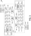
- the pass band of the subscriber device 105-2 installed in the base B needs to be inverted from the pass band of a WDM filter 140-1 connected to the subscriber device 105-1.
- the pass band of the uplink signal of the subscriber device 105-1 needs to be set to the pass band of the downlink signal in a WDM filter 140-2 connected to the subscriber device 105-2, and the pass band of the downlink signal of the subscriber device 105-1 needs to be set to the pass band of the uplink signal in the WDM filter 140-2.
- the uplink wiring and the downlink wiring for converting simplex and duplex are different for each base, which leads to complication of field work.
- the optical communication system 1 according to the first embodiment by using a circulator instead of the WDM filter, since the same uplink and downlink wirings can be used at each base, it is possible to eliminate the complexity of the field wiring work.
- the subscriber device 105-1 installed in the base A, the subscriber device 105-2 installed in the base B, and a subscriber device 105-3 (not illustrated) installed in a base C communicate with each other will be considered.
- the WDM filter 140-2 and a WDM filter 140-3 connected to the subscriber device 105-3 invert the pass band with respect to the pass band of the WDM filter 140-1, communication can be performed between the subscriber device 105-1 and the subscriber device 105-2 and between the subscriber device 105-1 and the subscriber device 105-3, but communication cannot be performed between the subscriber device 105-2 and the subscriber device 105-3.
- the same uplink and downlink wirings can be used at each base, and even in a situation where three or more subscriber devices are present, an optical signal can be transferred to a subscriber device regardless of the wavelength, so that communication between arbitrary two subscriber devices can be achieved.
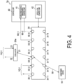
- Fig. 4 is a diagram illustrating a configuration example of an optical communication system 1a according to the second embodiment.
- the optical communication system 1a includes one or more subscriber devices 10, a circulator 20a, an optical SW 30, and a control unit 40.
- the subscriber device 10 and the optical SW 30, the circulator 20a and the optical SW 30, and the optical SW 30 and the control unit 40 are connected by using an optical transmission line.
- the circulator 20a and the optical SW 30 are examples of functional units forming the optical communication device.
- the optical communication system 1a is different from the optical communication system 1 in that the circulator 20a is connected not between the subscriber device 10 and the optical SW 30 but on the side of the port 32 of the optical SW 30.
- Other configurations of the optical communication system 1a are similar to those of the optical communication system 1. Therefore, differences from the optical communication system 1 will be described.
- a first port 21 of the circulator 20a is connected to the port 32 (port 32-3 in Fig. 4 ) of the optical SW 30 via an optical transmission line.
- a second port 22 and the third port 23 of the circulator 20 are connected to an optical transmission line (path 2 in Fig. 4 ) connected to another device.
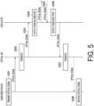
- Fig. 5 is a sequence diagram illustrating a flow of processing of the optical communication system 1a according to the second embodiment. Note that at the start of the processing of Fig. 5 , the connection relationship between ports of the optical SW 30 is set as illustrated in Fig. 4 .
- An optical transceiver of the subscriber device 10 transmits an optical signal of the wavelength allocated by the control unit 40 (step S201).
- the optical signal transmitted from the subscriber device 10 is input to a port 31 of the optical SW 30 via the optical transmission line.
- the subscriber device 10 is connected to a port 31-2 of the optical SW 30 via an optical transmission line 50. Therefore, the optical signal transmitted from the subscriber device 10 is input to the port 31-2 of the optical SW 30 via the optical transmission line 50.
- the port 31-1 of the optical SW 30 is connected to the port 32-3. Therefore, the optical signal input to the port 31-1 of the optical SW 30 is output from the port 32-3. Since the first port 21 of the circulator 20a is connected to the port 32-3, the optical SW 30 transfers the input optical signal to the first port 21 of the circulator 20a (step S203). The optical signal input to the first port 21 of the circulator 20a is output from the second port 22 (step S204).
- the optical signal output from the second port 22 of the circulator 20a is transferred to another device via the optical transmission line. Assume that a response to the optical signal transferred to the other device is input to the third port 23 of the circulator 20a (step S205). The optical signal input to the third port 23 of the circulator 20a is output from the first port 21 (step S206).
- the optical signal output from the first port 21 of the circulator 20 is input to the port 32-3 of the optical SW 30 via the optical transmission line.
- the optical signal input to the port 32-3 of the optical SW 30 is output from the port 31-2.
- the optical signal output from the port 31-2 of the optical SW 30 is input to the subscriber device 10 via the optical transmission line 50. In this manner, the optical SW 30 transfers the input optical signal to the subscriber device 10. As a result, the subscriber device 10 receives the optical signal (step S208).
- the optical communication system 1a configured as described above, it is possible to reduce the number of ports required for the optical SW 30 at the time of transferring an optical signal, as compared with the first embodiment.
- the circulator 20 and the optical SW 30 are connected by the two-core optical transmission line, and the side of the port 32 of the optical SW 30 is also connected by the two-core optical transmission line.
- the subscriber device 10 and the optical SW 30 are connected by a simplex optical transmission line, and the port 32 of the optical SW 30 and the circulator 20a are connected by a simplex optical transmission line.
- the port 32 of the optical SW 30 and the circulator 20a are connected by a simplex optical transmission line.
- a configuration in which a WDM filter is provided between a subscriber device 10 and an optical SW 30, and whether each port included in the WDM filter is an uplink port or a downlink port is changed depending on the wavelength range will be described.
- a direction from the subscriber device 10 toward the optical SW 30 will be referred to as an uplink direction
- a direction from the optical SW 30 toward the subscriber device 10 will be referred to as a downlink direction.
- Fig. 6 is a diagram illustrating a configuration example of an optical communication system 1b according to the third embodiment.
- the optical communication system 1b includes one or more subscriber devices 10, a WDM filter 25, an optical SW 30, and a control unit 40b.
- the subscriber device 10 and the WDM filter 25, the WDM filter 25 and the optical SW 30, and the optical SW 30 and the control unit 40b are connected by using an optical transmission line.
- the WDM filter 25 and the optical SW 30 are examples of functional units forming the optical communication device.
- the optical communication system 1b is different from the optical communication system 1 in that the WDM filter 25 is provided instead of the circulator 20 and the control unit 40b is provided instead of the control unit 40.
- Other configurations of the optical communication system 1b are similar to those of the optical communication system 1. Therefore, differences from the optical communication system 1 will be described.
- the control unit 40b includes a subscriber device management control unit 41b, an optical SW control unit 42b, and an uplink/downlink determination unit 43.
- the subscriber device management control unit 41b allocates a wavelength to the subscriber device 10. Further, the subscriber device management control unit 41b holds information on the pass band of each port (for example, second port 27 and third port 28) of the WDM filter 25. After allocating the uplink wavelength and the downlink wavelength to the subscriber device 10, the subscriber device management control unit 41b notifies the uplink/downlink determination unit 43 of information regarding the allocated wavelengths (hereinafter referred to as "wavelength information").
- the uplink/downlink determination unit 43 determines an uplink port and a downlink port among the plurality of ports included in the WDM filter 25 on the basis of the wavelength information notified from the subscriber device management control unit 41b. Incidentally, it is assumed that the uplink/downlink determination unit 43 holds in advance information of a port 31 of the optical SW 30 to which each port included in the WDM filter 25 is connected.
- the uplink/downlink determination unit 43 holds information indicating that the second port 27 of the WDM filter 25 is connected to a port 31-1 of the optical SW 30 and the third port 28 of the WDM filter 25 is connected to a port 31-2 of the optical SW 30.
- Information on the port 31 of the optical SW 30 to which each port of the WDM filter 25 is connected may be set in the control unit 40b by the administrator in advance.
- the optical SW control unit 42b controls the connection between ports of the optical SW 30 according to the determination result of the uplink/downlink determination unit 43. Specifically, the optical SW control unit 42b controls the connection between ports of the optical SW 30, so that the port 31 of the optical SW 30 to which the port (for example, second port 27 or third port 28) of the WDM filter 25 whose pass band is the uplink wavelength is connected is connected to the uplink port 32. Further, specifically, the optical SW control unit 42b controls the connection between ports of the optical SW 30, so that the port 31 of the optical SW 30 to which the port (for example, second port 27 or third port 28) of the WDM filter 25 whose pass band is the downlink wavelength is connected is connected to the downlink port 32.
- the wavelength range available in the relay section is 88 wavelengths of c-band
- the uplink wavelength and the downlink wavelength are selected from 88 wavelengths of c-band.
- the pass band of the WDM filter 25 is set to the 1st to 44th wavelengths in the second port 27 and the 45th to 88th wavelengths in the third port 28.
- the uplink/downlink determination unit 43 determines that the second port 27 of the WDM filter 25 is the uplink port and the third port 28 of the WDM filter 25 is the downlink port.
- the uplink/downlink determination unit 43 notifies the optical SW control unit 42b of the determination result.
- the optical SW control unit 42b controls the connection between ports of the optical SW 30, so that the port 31-1 of the optical SW 30 to which the second port 27 of the WDM filter 25 is connected is connected to an uplink port 32-3 according to the determination result notified from the uplink/downlink determination unit 43. Further, the optical SW control unit 42b controls the connection between ports of the optical SW 30, so that the port 31-2 of the optical SW 30 to which the third port 28 of the WDM filter 25 is connected is connected to a downlink port 32-4 according to the determination result notified from the uplink/downlink determination unit 43.
- the WDM filter 25 is an optical coupler (optical multiplexer/demultiplexer) that multiplexes or demultiplexes the input optical signals.
- the WDM filter 25 has three ports (for example, first port 26, second port 27, and third port 28).
- the first port 26 of the WDM filter 25 is connected to the subscriber device 10 via an optical transmission line.
- the second port 27 of the WDM filter 25 is connected to the optical SW 30 via an optical transmission line 50-1.
- the third port 28 of the WDM filter 25 is connected to the optical SW 30 via an optical transmission line 50-2.
- An optical signal input to the first port 26 is output from the second port 27 or the third port 28 depending on the wavelength. Assume that the pass bands of the wavelengths in the second port 27 and the third port 28 of the WDM filter 25 are set in advance. An optical signal input from the second port 27 or the third port 28 is multiplexed and output from the first port 26.
- the uplink/downlink determination unit 43 determines which of the port 31-(x+1) and the port 31-(x+2) is to be the uplink or the downlink, and there is no need to separately set the port information.
- the WDM filter 25 is one aspect of a transfer unit.
- the uplink/downlink determination unit 43 determines that the second port 27 of the WDM filter 25 is the downlink port and the third port 28 of the WDM filter 25 is the uplink port.
- the uplink/downlink determination unit 43 notifies the optical SW control unit 42b of the determination result.
- the optical SW control unit 42b controls the connection relationship between ports of the optical SW 30 as illustrated in Fig. 7 according to the determination result notified from the uplink/downlink determination unit 43.
- Fig. 7 is a diagram illustrating an example of a connection relationship between other ports of the optical SW 30 according to the third embodiment.
- the optical SW control unit 42b controls the connection between ports of the optical SW 30, so that the port 31-1 of the optical SW 30 to which the second port 27 of the WDM filter 25 is connected is connected to the downlink port 32-4.
- optical SW control unit 42b controls the connection between ports of the optical SW 30, so that the port 31-2 of the optical SW 30 to which the third port 28 of the WDM filter 25 is connected is connected to the uplink port 32-3 according to the determination result notified from the uplink/downlink determination unit 43.
- the uplink wavelength or the downlink wavelength is selected from one pass band, but in the optical communication system 1b configured as described above, the uplink wavelength or the downlink wavelength can be selected from both pass bands, so that the usable wavelength range is expanded as compared with the conventional method.
- the same uplink and downlink wirings of the WDM filter 25 can be used at each base and the uplink and downlink can be remotely changed by the optical SW 30, it is possible to eliminate the complexity of the local wiring work. Further, even in a situation where there are three or more subscriber devices, since an optical signal can be transferred to the subscriber device regardless of the wavelength, communication between arbitrary subscriber devices can be achieved.
- control units 40 and 40b in the above-described embodiments may be implemented by a computer.
- a program for implementing the functions may be recorded in a computer-readable recording medium, and the program recorded in the recording medium may be read and executed by a computer system to implement the functions.
- the "computer system” mentioned herein includes an OS and hardware such as peripheral devices.
- the "computer-readable recording medium” refers to a portable medium such as a flexible disk, a magneto-optical disc, a ROM, or a CD-ROM or a storage device such as a hard disk included in the computer system.
- the "computer-readable recording medium” may include a medium that dynamically holds the program for a short time, such as a communication line in a case where the program is transmitted via a network such as the Internet or a communication line such as a telephone line, and a medium that holds the program for a certain period of time, such as a volatile memory inside the computer system serving as a server or a client in that case.
- the above program may be for implementing some of the functions described above, may implement the functions described above by a combination with a program already recorded in the computer system, or may be implemented by using a programmable logic device such as an FPGA.
- the present invention can be applied to optical communication systems.
Landscapes
- Engineering & Computer Science (AREA)
- Computer Networks & Wireless Communication (AREA)
- Signal Processing (AREA)
- Computing Systems (AREA)
- Physics & Mathematics (AREA)
- Electromagnetism (AREA)
- Optical Communication System (AREA)
Abstract
Description
- The present invention relates to an optical communication device, an optical communication system, and an optical communication method.
- There has been conventionally proposed an optical communication device capable of relaying an optical signal in accordance with a destination while reducing delay (see, for example, Patent Literature 1).
Fig. 8 illustrates a configuration example of anoptical communication system 100 including a conventional optical communication device. Theoptical communication system 100 includes anoptical SW 110 and acontrol unit 115 forming the optical communication device. AWDM filter 140 and thecontrol unit 115 are connected to theoptical SW 110. - The
optical SW 110 is connected to a plurality of optical transmission lines and outputs an optical signal input from any of the optical transmission lines to another optical transmission line. Theoptical SW 110 ofFig. 8 includes ports 111-1 to 111-6 and ports 112-1 to 112-6. Theoptical SW 110 and theWDM filter 140 are connected by a duplex optical transmission line. For example, the port 111-1 of theoptical SW 110 and theWDM filter 140 are connected via an optical transmission line 135-1, and the port 111-2 of theoptical SW 110 and theWDM filter 140 are connected via an optical transmission line 135-2. - The
optical SW 110 and thecontrol unit 115 are connected by a duplex optical transmission line. For example, the port 112-5 of theoptical SW 110 and thecontrol unit 115 are connected via an optical transmission line 136-1, and the port 112-6 of theoptical SW 110 and thecontrol unit 115 are connected via an optical transmission line 136-2. - The
control unit 115 includes a subscriber devicemanagement control unit 120 and an opticalSW control unit 130. The subscriber devicemanagement control unit 120 allocates a wavelength to asubscriber device 105. The opticalSW control unit 130 switches the path of theoptical SW 110. - Conventionally, regarding the number of optical transmission lines, in an optical access section between the
subscriber device 105 connected to theWDM filter 140 and theoptical SW 110, the uplink and the downlink are often set to simplex transmission with different wavelengths, but in the relay, the same wavelength is often used with separate uplink and downlink optical transmission lines. In the example illustrated inFig. 8 , it is assumed that an optical signal from thesimplex subscriber device 105 is transmitted by duplex relay, and the optical signal is converted into duplex by theWDM filter 140. Since the wavelengths are different between the uplink and the downlink, the uplink and the downlink can be separated by changing the pass wavelength band of each port of the WDM filter. - Even in a case where the relay is simplex, arrayed waveguide grating (AWG) may be used to multiplex optical signals transmitted from a plurality of subscriber devices. Since the wavelength that can be accommodated for each port is fixed in the AWG, it is necessary to separate the uplink and the downlink once by the
WDM filter 140 and connect to the AWG installed between theoptical SW 110 and the optical transmission line through separate ports as in the configuration illustrated inFig. 8 . - In a sequence in which the
subscriber device 105 first sends a control signal to the subscriber devicemanagement control unit 120 and the subscriber devicemanagement control unit 120 notifies thesubscriber device 105 of the use wavelength, the uplink port can be identified by presence or absence of optical power by the control signal, but the downlink port corresponding to thesubscriber device 105 cannot be found without prior information. Therefore, it is necessary to determine in advance where to set the downlink port with respect to the uplink port of acertain subscriber device 105. For example, it is necessary to determine in advance by a rule such as arranging the uplink and the downlink next to each other. - Patent Literature 1:
WO 2021/131202 A - An optical transceiver included in the
subscriber device 105 is desirably a wavelength-tunable optical transmitter/receiver, and in that case, communication can be performed at an arbitrary wavelength. However, the available wavelength range is limited due to the pass band of theWDM filter 140. For example, in a case where the usable wavelength range in a relay section is 88 wavelengths of c-band, the uplink and the downlink are selected from among them. When the pass band of the port of theWDM filter 140 connected to a port 111-1 of theoptical SW 110 is set to the 1st to 44th wavelengths and the pass band of the port of theWDM filter 140 connected to a port 111-2 of theoptical SW 110 is set to the 45th to 88th wavelengths, there is a problem that the wavelength range that can be used in the uplink or the downlink is halved. As a result, since thesubscriber device 105 performs communication using a wavelength not used in other communication including the relay section, narrowing the usable wavelength range leads to loss of communication opportunities. - In view of the above circumstances, an object of the present invention is to provide a technique capable of curbing the restriction on usable uplink and downlink wavelength ranges.
- One aspect of the present invention is an optical communication device including an optical switch that is connected to a plurality of optical transmission lines and outputs an optical signal input from any of the optical transmission lines to another optical transmission line, and a transfer unit configured to convert simplex transmission into duplex transmission or converts duplex transmission into simplex transmission between a subscriber device and the optical switch or between a first port of the optical switch to which the subscriber device is directly or indirectly connected and a second port opposite to the first port, and transfers the optical signal so as not to cause interference between uplink and downlink.
- One aspect of the present invention is an optical communication system including: an optical switch that is connected to a plurality of optical transmission lines and outputs an optical signal input from any of the optical transmission lines to another optical transmission line; a transfer unit configured to convert simplex transmission into duplex transmission or converts duplex transmission into simplex transmission by multiplexing or demultiplexing an input optical signal between a subscriber device and the optical switch, and transfers the optical signal so as not to cause interference between uplink and downlink; an uplink/downlink determination unit configured to determine an uplink port and a downlink port among a plurality of ports included in the transfer unit on the basis of information on wavelengths used for the uplink and the downlink allocated to the subscriber device; and an optical switch control unit configured to control connection between ports of the optical switch according to a determination result of the uplink/downlink determination unit.
- One aspect of the present invention is an optical communication method including an optical switch connected to a plurality of optical transmission lines outputting an optical signal input from any of the optical transmission lines to another optical transmission line, and converting simplex transmission into duplex transmission or converting duplex transmission into simplex transmission between a subscriber device and the optical switch or between a first port of the optical switch to which the subscriber device is directly or indirectly connected and a second port opposite to the first port, and transferring the optical signal so as not to cause interference between uplink and downlink.
- One aspect of the present invention is an optical communication method including: an optical switch connected to a plurality of optical transmission lines outputting an optical signal input from any of the optical transmission lines to another optical transmission line; a transfer unit converting simplex transmission into duplex transmission or converting duplex transmission into simplex transmission by multiplexing or demultiplexing an input optical signal between a subscriber device and the optical switch, and transferring the optical signal so as not to cause interference between uplink and downlink; determining an uplink port and a downlink port among a plurality of ports included in the transfer unit on the basis of information on wavelengths used for the uplink and the downlink allocated to the subscriber device; and controlling connection between ports of the optical switch according to a determination result.
- According to the present invention, it is possible to curb the restriction on usable uplink and downlink wavelength ranges.
-
-
Fig. 1 is a diagram illustrating a configuration example of an optical communication system according to a first embodiment. -
Fig. 2 is a sequence diagram illustrating a flow of processing of the optical communication system according to the first embodiment. -
Fig. 3 is a diagram for describing a problem of conventional technology. -
Fig. 4 is a diagram illustrating a configuration example of an optical communication system according to a second embodiment. -
Fig. 5 is a sequence diagram illustrating a flow of processing of the optical communication system according to the second embodiment. -
Fig. 6 is a diagram illustrating a configuration example of an optical communication system according to a third embodiment. -
Fig. 7 is a diagram illustrating an example of a connection relationship between other ports of an optical SW according to the third embodiment. -
Fig. 8 illustrates a configuration example of an optical communication system including a conventional optical communication device. - Hereinafter, embodiments of the present invention will be described with reference to drawings.
-
Fig. 1 is a diagram illustrating a configuration example of anoptical communication system 1 according to a first embodiment. Theoptical communication system 1 includes one ormore subscriber devices 10, acirculator 20, anoptical SW 30, and acontrol unit 40. Thesubscriber device 10 and thecirculator 20, thecirculator 20 and theoptical SW 30, and theoptical SW 30 and thecontrol unit 40 are connected by using an optical transmission line. The optical transmission line is, for example, an optical fiber. Thecirculator 20 and theoptical SW 30 are examples of functional units forming the optical communication device. - The
subscriber device 10 includes an optical transceiver. The optical transceiver is a wavelength-tunable optical transmitter/receiver. Therefore, thesubscriber device 10 can perform communication using an arbitrary wavelength. The wavelength used for communication by thesubscriber device 10 is allocated by thecontrol unit 40. The optical transceiver may be an optical transceiver having an auxiliary management and control channel (AMCC) function. In this case, the wavelength used by thesubscriber device 10 is controlled via a control signal superimposed by the AMCC. Thesubscriber device 10 is, for example, an optical network unit (ONU) installed in a subscriber's home. - The
circulator 20 has at least three or more ports. In the following description, it is assumed that thecirculator 20 has three ports (for example,first port 21,second port 22, and third port 23). Thefirst port 21 of thecirculator 20 is connected to thesubscriber device 10 via an optical transmission line. Thesecond port 22 of thecirculator 20 is connected to theoptical SW 30 via an optical transmission line 50-1. Thethird port 23 of thecirculator 20 is connected to theoptical SW 30 via an optical transmission line 50-2. An optical signal input to thefirst port 21 is output from thesecond port 22. An optical signal input to thesecond port 22 is output from thethird port 23. An optical signal input to thethird port 23 is output from thefirst port 21. - As described above, the
circulator 20 has directivity and port selectivity, but no wavelength selectivity. Therefore, an optical signal output from thesubscriber device 10 can be output to theoptical SW 30 regardless of the wavelength of the optical signal. Further, thecirculator 20 can transfer an optical signal transferred from theoptical SW 30 to thesubscriber device 10 regardless of the wavelength of the optical signal. Thecirculator 20 is one aspect of a transfer unit. - The
optical SW 30 is an optical switch having M (M is integer of two or more) ports 31 and N (N is integer of two or more) ports 32. In the embodiment, the numbers of M and N are assumed to be six. An optical signal input to a certain port of theoptical SW 30 is output from another port. For example, an optical signal input to the port 31 of theoptical SW 30 is output from the port 32. In theoptical SW 30, a connection relationship between the port 31 and the port 32 is set under the control of thecontrol unit 40. - The
second port 22 of thecirculator 20 is connected to a port 31-1 of theoptical SW 30 via the optical transmission line 50-1, thethird port 23 of thecirculator 20 is connected to a port 31-2 of theoptical SW 30 via the optical transmission line 50-2, thecontrol unit 40 is connected to a port 32-5 of theoptical SW 30 via an optical transmission line 60-1, and thecontrol unit 40 is connected to a port 32-6 of theoptical SW 30 via an optical transmission line 60-2. - An optical transmission line for two-core connection to another device is connected to each of the pair of a port 32-1 and a port 32-2 and the pair of a port 32-3 and a port 32-4 of the
optical SW 30. The other device is an optical SW, a circulator, or the like installed in a base different from the base where theoptical SW 30 and thecontrol unit 40 are installed. - The
control unit 40 controls at least thesubscriber device 10 and theoptical SW 30. Here, the control of thesubscriber device 10 is, for example, allocation of a light emission wavelength to thesubscriber device 10, or a light stop instruction, a wavelength change instruction, or the like to thesubscriber device 10. The control of theoptical SW 30 is, for example, connection setting between ports of theoptical SW 30, setting of an optical path, and the like. - The
control unit 40 includes a subscriber devicemanagement control unit 41 and an opticalSW control unit 42. The subscriber devicemanagement control unit 41 allocates a wavelength to thesubscriber device 10. In a case where the subscriber devicemanagement control unit 41 allocates a wavelength to thesubscriber device 10, the opticalSW control unit 42 sets a path between ports of theoptical SW 30 so as to connect thesubscriber device 10 and the subscriber devicemanagement control unit 41. - The subscriber device
management control unit 41 stores a management table. The management table includes information for identifying thesubscriber devices 10, information regarding a wavelength allocated to eachsubscriber device 10, and information regarding theoptical SW 30 to which thesubscriber device 10 is connected (for example, information regarding port to whichsubscriber device 10 is connected). - The optical
SW control unit 42 controls connection between ports of theoptical SW 30. Specifically, the opticalSW control unit 42 controls connection between ports of theoptical SW 30 so that an optical signal transmitted from thesubscriber device 10 is transferred to a subscriber device to be the transmission destination. For example, in a case where the subscriber device to be the transmission destination is connected to apath 2, the opticalSW control unit 42 controls the connection between the ports so as to connect the port 31-1 and the port 32-3. Controlling the connection between the ports means setting a path so that a certain port and another port are connected. - Further, the optical
SW control unit 42 controls connection between ports of theoptical SW 30 so that an optical signal addressed to thesubscriber device 10 is transferred to thesubscriber device 10. For example, in a case where a communication target subscriber device is connected to thepath 2, the opticalSW control unit 42 controls connection between the ports so as to connect the port 31-2 and the port 32-4. Thecontrol unit 40 includes one or more processors. Note that each functional unit included in thecontrol unit 40 is implemented by mounting thecontrol unit 40 on one server. -
Fig. 2 is a sequence diagram illustrating a flow of processing of theoptical communication system 1 according to the first embodiment. Note that at the start of the processing ofFig. 2 , the connection relationship between ports of theoptical SW 30 is set as illustrated inFig. 1 . - An optical transceiver of the
subscriber device 10 transmits an optical signal of the wavelength allocated by the control unit 40 (step S101). The optical signal transmitted from thesubscriber device 10 is input to thefirst port 21 of thecirculator 20 via the optical transmission line. The optical signal input to thefirst port 21 of thecirculator 20 is output from the second port 22 (step S102). The optical signal output from thesecond port 22 of thecirculator 20 is input to the port 31-1 of theoptical SW 30 via the optical transmission line 50-1 (step S103). - The port 31-1 of the
optical SW 30 is connected to the port 32-3. Therefore, the optical signal input to the port 31-1 of theoptical SW 30 is output from the port 32-3. In this manner, theoptical SW 30 transfers the input optical signal to another device (step S104). Assume that a response to the optical signal transferred to the other device is input to the port 32-4 of the optical SW 30 (step S105). - The port 32-4 of the
optical SW 30 is connected to the port 31-2. Therefore, the optical signal input to the port 32-4 of theoptical SW 30 is output from the port 31-2. In this manner, theoptical SW 30 transfers the input optical signal to the other device (step S106). The optical signal output from the port 31-2 of theoptical SW 30 is input to thethird port 23 of thecirculator 20. The optical signal input to thethird port 23 of thecirculator 20 is output from the first port 21 (step S107). - The optical signal output from the
first port 21 of thecirculator 20 is input to thesubscriber device 10 via the optical transmission line 50-2 (step S108). As a result, thesubscriber device 10 receives the optical signal (step S109). - According to the
optical communication system 1 configured as described above, it is possible to curb the restriction on usable uplink and downlink wavelength ranges. Specifically, in theoptical communication system 1, thecirculator 20 is used as a conversion unit from simplex to duplex between thesubscriber device 10 and theoptical SW 30. Since use of thecirculator 20 prevents interference between uplink signals and downlink signals, the same wavelength can be used for the uplink and the downlink. Therefore, it is possible to curb the restriction on usable uplink and downlink wavelength ranges. - Conventionally, as illustrated in
Fig. 3 , in a case where communication is performed between a subscriber device 105-1 installed in a base A and a subscriber device 105-2 installed in a base B, with respect to the subscriber device 105-1 installed in the base A, the pass band of the subscriber device 105-2 installed in the base B needs to be inverted from the pass band of a WDM filter 140-1 connected to the subscriber device 105-1. That is, the pass band of the uplink signal of the subscriber device 105-1 needs to be set to the pass band of the downlink signal in a WDM filter 140-2 connected to the subscriber device 105-2, and the pass band of the downlink signal of the subscriber device 105-1 needs to be set to the pass band of the uplink signal in the WDM filter 140-2. For this reason, the uplink wiring and the downlink wiring for converting simplex and duplex are different for each base, which leads to complication of field work. On the other hand, in theoptical communication system 1 according to the first embodiment, by using a circulator instead of the WDM filter, since the same uplink and downlink wirings can be used at each base, it is possible to eliminate the complexity of the field wiring work. - Further, a case where the subscriber device 105-1 installed in the base A, the subscriber device 105-2 installed in the base B, and a subscriber device 105-3 (not illustrated) installed in a base C communicate with each other will be considered. For example, when the WDM filter 140-2 and a WDM filter 140-3 connected to the subscriber device 105-3 invert the pass band with respect to the pass band of the WDM filter 140-1, communication can be performed between the subscriber device 105-1 and the subscriber device 105-2 and between the subscriber device 105-1 and the subscriber device 105-3, but communication cannot be performed between the subscriber device 105-2 and the subscriber device 105-3. That is, there has also been a problem that communication between arbitrary two subscriber devices cannot be provided in a case where three or more subscriber devices are present. On the other hand, in the
optical communication system 1 according to the first embodiment, by using the circulator, the same uplink and downlink wirings can be used at each base, and even in a situation where three or more subscriber devices are present, an optical signal can be transferred to a subscriber device regardless of the wavelength, so that communication between arbitrary two subscriber devices can be achieved. - In a second embodiment, a configuration in which a circulator is provided on the side of a port 32 of an optical SW 30 (between
optical SW 30 and another device) will be described. -
Fig. 4 is a diagram illustrating a configuration example of an optical communication system 1a according to the second embodiment. The optical communication system 1a includes one ormore subscriber devices 10, acirculator 20a, anoptical SW 30, and acontrol unit 40. Thesubscriber device 10 and theoptical SW 30, thecirculator 20a and theoptical SW 30, and theoptical SW 30 and thecontrol unit 40 are connected by using an optical transmission line. Thecirculator 20a and theoptical SW 30 are examples of functional units forming the optical communication device. - The optical communication system 1a is different from the
optical communication system 1 in that thecirculator 20a is connected not between thesubscriber device 10 and theoptical SW 30 but on the side of the port 32 of theoptical SW 30. Other configurations of the optical communication system 1a are similar to those of theoptical communication system 1. Therefore, differences from theoptical communication system 1 will be described. - A
first port 21 of thecirculator 20a is connected to the port 32 (port 32-3 inFig. 4 ) of theoptical SW 30 via an optical transmission line. Asecond port 22 and thethird port 23 of thecirculator 20 are connected to an optical transmission line (path 2 inFig. 4 ) connected to another device. -
Fig. 5 is a sequence diagram illustrating a flow of processing of the optical communication system 1a according to the second embodiment. Note that at the start of the processing ofFig. 5 , the connection relationship between ports of theoptical SW 30 is set as illustrated inFig. 4 . - An optical transceiver of the
subscriber device 10 transmits an optical signal of the wavelength allocated by the control unit 40 (step S201). The optical signal transmitted from thesubscriber device 10 is input to a port 31 of theoptical SW 30 via the optical transmission line. In the example illustrated inFig. 4 , thesubscriber device 10 is connected to a port 31-2 of theoptical SW 30 via anoptical transmission line 50. Therefore, the optical signal transmitted from thesubscriber device 10 is input to the port 31-2 of theoptical SW 30 via theoptical transmission line 50. - The port 31-1 of the
optical SW 30 is connected to the port 32-3. Therefore, the optical signal input to the port 31-1 of theoptical SW 30 is output from the port 32-3. Since thefirst port 21 of thecirculator 20a is connected to the port 32-3, theoptical SW 30 transfers the input optical signal to thefirst port 21 of thecirculator 20a (step S203). The optical signal input to thefirst port 21 of thecirculator 20a is output from the second port 22 (step S204). - The optical signal output from the
second port 22 of thecirculator 20a is transferred to another device via the optical transmission line. Assume that a response to the optical signal transferred to the other device is input to thethird port 23 of thecirculator 20a (step S205). The optical signal input to thethird port 23 of thecirculator 20a is output from the first port 21 (step S206). - The optical signal output from the
first port 21 of thecirculator 20 is input to the port 32-3 of theoptical SW 30 via the optical transmission line. The optical signal input to the port 32-3 of theoptical SW 30 is output from the port 31-2. The optical signal output from the port 31-2 of theoptical SW 30 is input to thesubscriber device 10 via theoptical transmission line 50. In this manner, theoptical SW 30 transfers the input optical signal to thesubscriber device 10. As a result, thesubscriber device 10 receives the optical signal (step S208). - According to the optical communication system 1a configured as described above, it is possible to reduce the number of ports required for the
optical SW 30 at the time of transferring an optical signal, as compared with the first embodiment. Specifically, in theoptical communication system 1 according to the first embodiment, thecirculator 20 and theoptical SW 30 are connected by the two-core optical transmission line, and the side of the port 32 of theoptical SW 30 is also connected by the two-core optical transmission line. On the other hand, in the optical communication system 1a according to the second embodiment, thesubscriber device 10 and theoptical SW 30 are connected by a simplex optical transmission line, and the port 32 of theoptical SW 30 and thecirculator 20a are connected by a simplex optical transmission line. As a result, it is possible to reduce the number of ports required for theoptical SW 30 at the time of transferring the optical signal. - In a third embodiment, a configuration in which a WDM filter is provided between a
subscriber device 10 and anoptical SW 30, and whether each port included in the WDM filter is an uplink port or a downlink port is changed depending on the wavelength range will be described. In the following description, a direction from thesubscriber device 10 toward theoptical SW 30 will be referred to as an uplink direction, and a direction from theoptical SW 30 toward thesubscriber device 10 will be referred to as a downlink direction. -
Fig. 6 is a diagram illustrating a configuration example of anoptical communication system 1b according to the third embodiment. Theoptical communication system 1b includes one ormore subscriber devices 10, aWDM filter 25, anoptical SW 30, and acontrol unit 40b. Thesubscriber device 10 and theWDM filter 25, theWDM filter 25 and theoptical SW 30, and theoptical SW 30 and thecontrol unit 40b are connected by using an optical transmission line. TheWDM filter 25 and theoptical SW 30 are examples of functional units forming the optical communication device. - The
optical communication system 1b is different from theoptical communication system 1 in that theWDM filter 25 is provided instead of thecirculator 20 and thecontrol unit 40b is provided instead of thecontrol unit 40. Other configurations of theoptical communication system 1b are similar to those of theoptical communication system 1. Therefore, differences from theoptical communication system 1 will be described. - The
control unit 40b includes a subscriber devicemanagement control unit 41b, an opticalSW control unit 42b, and an uplink/downlink determination unit 43. The subscriber devicemanagement control unit 41b allocates a wavelength to thesubscriber device 10. Further, the subscriber devicemanagement control unit 41b holds information on the pass band of each port (for example,second port 27 and third port 28) of theWDM filter 25. After allocating the uplink wavelength and the downlink wavelength to thesubscriber device 10, the subscriber devicemanagement control unit 41b notifies the uplink/downlink determination unit 43 of information regarding the allocated wavelengths (hereinafter referred to as "wavelength information"). - The uplink/
downlink determination unit 43 determines an uplink port and a downlink port among the plurality of ports included in theWDM filter 25 on the basis of the wavelength information notified from the subscriber devicemanagement control unit 41b. Incidentally, it is assumed that the uplink/downlink determination unit 43 holds in advance information of a port 31 of theoptical SW 30 to which each port included in theWDM filter 25 is connected. - In the case of the configuration illustrated in
Fig. 6 , the uplink/downlink determination unit 43 holds information indicating that thesecond port 27 of theWDM filter 25 is connected to a port 31-1 of theoptical SW 30 and thethird port 28 of theWDM filter 25 is connected to a port 31-2 of theoptical SW 30. Information on the port 31 of theoptical SW 30 to which each port of theWDM filter 25 is connected may be set in thecontrol unit 40b by the administrator in advance. - The optical
SW control unit 42b controls the connection between ports of theoptical SW 30 according to the determination result of the uplink/downlink determination unit 43. Specifically, the opticalSW control unit 42b controls the connection between ports of theoptical SW 30, so that the port 31 of theoptical SW 30 to which the port (for example,second port 27 or third port 28) of theWDM filter 25 whose pass band is the uplink wavelength is connected is connected to the uplink port 32. Further, specifically, the opticalSW control unit 42b controls the connection between ports of theoptical SW 30, so that the port 31 of theoptical SW 30 to which the port (for example,second port 27 or third port 28) of theWDM filter 25 whose pass band is the downlink wavelength is connected is connected to the downlink port 32. - Specific processing of the
optical communication system 1b will be described according to an example. Assume that the wavelength range available in the relay section is 88 wavelengths of c-band, and the uplink wavelength and the downlink wavelength are selected from 88 wavelengths of c-band. The pass band of theWDM filter 25 is set to the 1st to 44th wavelengths in thesecond port 27 and the 45th to 88th wavelengths in thethird port 28. Here, in a case where the subscriber devicemanagement control unit 41b allocates thewavelength 10 as the uplink wavelength and thewavelength 50 as the downlink wavelength to thesubscriber device 10, the uplink/downlink determination unit 43 determines that thesecond port 27 of theWDM filter 25 is the uplink port and thethird port 28 of theWDM filter 25 is the downlink port. The uplink/downlink determination unit 43 notifies the opticalSW control unit 42b of the determination result. - The optical
SW control unit 42b controls the connection between ports of theoptical SW 30, so that the port 31-1 of theoptical SW 30 to which thesecond port 27 of theWDM filter 25 is connected is connected to an uplink port 32-3 according to the determination result notified from the uplink/downlink determination unit 43. Further, the opticalSW control unit 42b controls the connection between ports of theoptical SW 30, so that the port 31-2 of theoptical SW 30 to which thethird port 28 of theWDM filter 25 is connected is connected to a downlink port 32-4 according to the determination result notified from the uplink/downlink determination unit 43. - The
WDM filter 25 is an optical coupler (optical multiplexer/demultiplexer) that multiplexes or demultiplexes the input optical signals. TheWDM filter 25 has three ports (for example,first port 26,second port 27, and third port 28). Thefirst port 26 of theWDM filter 25 is connected to thesubscriber device 10 via an optical transmission line. Thesecond port 27 of theWDM filter 25 is connected to theoptical SW 30 via an optical transmission line 50-1. Thethird port 28 of theWDM filter 25 is connected to theoptical SW 30 via an optical transmission line 50-2. - An optical signal input to the
first port 26 is output from thesecond port 27 or thethird port 28 depending on the wavelength. Assume that the pass bands of the wavelengths in thesecond port 27 and thethird port 28 of theWDM filter 25 are set in advance. An optical signal input from thesecond port 27 or thethird port 28 is multiplexed and output from thefirst port 26. - In a case where the
second port 27 and thethird port 28 of theWDM filter 25 are connected to arbitrary ports of theoptical SW 30, it is necessary to separately set the port information in the uplink/downlink determination unit 43. Alternatively, it is also conceivable to use an operation rule in which thesecond port 27 and thethird port 28 of theWDM filter 25 are connected to, for example, a port 31-(x+1) and a port 31-(x+2) (x is integer of zero or more) of theoptical SW 30. In this case, the uplink/downlink determination unit 43 determines which of the port 31-(x+1) and the port 31-(x+2) is to be the uplink or the downlink, and there is no need to separately set the port information. TheWDM filter 25 is one aspect of a transfer unit. - Next, another example of specific processing of the
optical communication system 1b will be described. In a case where the subscriber devicemanagement control unit 41b allocates the wavelength 60 as the uplink wavelength and thewavelength 20 as the downlink wavelength to thesubscriber device 10, the uplink/downlink determination unit 43 determines that thesecond port 27 of theWDM filter 25 is the downlink port and thethird port 28 of theWDM filter 25 is the uplink port. The uplink/downlink determination unit 43 notifies the opticalSW control unit 42b of the determination result. - The optical
SW control unit 42b controls the connection relationship between ports of theoptical SW 30 as illustrated inFig. 7 according to the determination result notified from the uplink/downlink determination unit 43.Fig. 7 is a diagram illustrating an example of a connection relationship between other ports of theoptical SW 30 according to the third embodiment. The opticalSW control unit 42b controls the connection between ports of theoptical SW 30, so that the port 31-1 of theoptical SW 30 to which thesecond port 27 of theWDM filter 25 is connected is connected to the downlink port 32-4. Further, the opticalSW control unit 42b controls the connection between ports of theoptical SW 30, so that the port 31-2 of theoptical SW 30 to which thethird port 28 of theWDM filter 25 is connected is connected to the uplink port 32-3 according to the determination result notified from the uplink/downlink determination unit 43. - Conventionally, the uplink wavelength or the downlink wavelength is selected from one pass band, but in the
optical communication system 1b configured as described above, the uplink wavelength or the downlink wavelength can be selected from both pass bands, so that the usable wavelength range is expanded as compared with the conventional method. Further, since the same uplink and downlink wirings of theWDM filter 25 can be used at each base and the uplink and downlink can be remotely changed by theoptical SW 30, it is possible to eliminate the complexity of the local wiring work. Further, even in a situation where there are three or more subscriber devices, since an optical signal can be transferred to the subscriber device regardless of the wavelength, communication between arbitrary subscriber devices can be achieved. - In the conventional configuration as illustrated in
Fig. 3 , in a case where a plurality of wavelengths is multiplexed and demultiplexed by AWG with simplex relay, it is not necessary to determine the uplink and the downlink. In the third embodiment, in a case of duplex relay and the uplink and the downlink are transmitted through different optical transmission lines, it is necessary to determine and control the uplink and the downlink. - In the first embodiment and the second embodiment, the description has been given on the assumption that the relay section is duplex, but the present invention is also applicable to a case where the relay section is simplex. Even in a case where the relay is simplex, in a case where signals of a plurality of subscriber devices are multiplexed by the AWG, it is necessary to separate the uplink and the downlink once as described above, and the configurations described in the first embodiment and the second embodiment may be used for the separation.
- Some functional units of the
control units - In addition, the "computer-readable recording medium" refers to a portable medium such as a flexible disk, a magneto-optical disc, a ROM, or a CD-ROM or a storage device such as a hard disk included in the computer system. Further, the "computer-readable recording medium" may include a medium that dynamically holds the program for a short time, such as a communication line in a case where the program is transmitted via a network such as the Internet or a communication line such as a telephone line, and a medium that holds the program for a certain period of time, such as a volatile memory inside the computer system serving as a server or a client in that case. The above program may be for implementing some of the functions described above, may implement the functions described above by a combination with a program already recorded in the computer system, or may be implemented by using a programmable logic device such as an FPGA.
- As described above, the embodiments of the present invention have been described in detail with reference to the drawings. On the other hand, the specific configuration is not limited to the embodiments, and includes design and the like without departing from the spirit of the present invention.
- The present invention can be applied to optical communication systems.
-
- 10
- Subscriber device
- 20, 20a
- Circulator
- 25
- WDM filter
- 30
- Optical SW
- 40, 40b
- Control unit
- 41,41b
- Subscriber device management control unit
- 42, 42b
- Optical SW control unit
- 43
- uplink/downlink determination unit
Claims (8)
- An optical communication device comprisingan optical switch that is connected to a plurality of optical transmission lines and outputs an optical signal input from any of the optical transmission lines to another optical transmission line, anda transfer unit configured to convert simplex transmission into duplex transmission or converts duplex transmission into simplex transmission between a subscriber device and the optical switch or between a first port of the optical switch to which the subscriber device is directly or indirectly connected and a second port opposite to the first port, and transfers the optical signal so as not to cause interference between uplink and downlink.
- The optical communication device according to claim 1, wherein:the transfer unit is a circulator;the circulator includes a first port, a second port, and a third port;the first port is connected to the subscriber device;the second port is connected to an uplink first port among a plurality of first ports included in the optical switch;the third port is connected to a downlink first port among the plurality of first ports included in the optical switch; andthe circulator outputs an optical signal input to the first port to the uplink first port connected to the second port, and outputs an optical signal input to the third port to the subscriber device connected to the first port.
- The optical communication device according to claim 1, wherein:the transfer unit is a circulator;the circulator includes a first port, a second port, and a third port;the first port is connected to a second port of the optical switch;the second port is connected to an uplink optical transmission line;the third port is connected to a downlink optical transmission line; andthe circulator outputs an optical signal input to the first port to the uplink optical transmission line connected to the second port, and outputs an optical signal input to the third port to the second port of the optical switch connected to the first port.
- The optical communication device according to any one of claims 1 to 3 further comprising, on the side of the second port of the optical switch, a wavelength multiplexer/demultiplexer configured to multiplex or demultiplex an input optical signal, wherein
an uplink optical signal and a downlink optical signal are transmitted by simplex transmission. - An optical communication system comprising:an optical switch that is connected to a plurality of optical transmission lines and outputs an optical signal input from any of the optical transmission lines to another optical transmission line;a transfer unit configured to convert simplex transmission into duplex transmission or converts duplex transmission into simplex transmission by multiplexing or demultiplexing an input optical signal between a subscriber device and the optical switch, and transfers the optical signal so as not to cause interference between uplink and downlink;an uplink/downlink determination unit configured to determine an uplink port and a downlink port among a plurality of ports included in the transfer unit on a basis of information on wavelengths used for the uplink and the downlink allocated to the subscriber device; andan optical switch control unit configured to control connection between ports of the optical switch according to a determination result of the uplink/downlink determination unit.
- The optical communication system according to claim 5, wherein
the optical switch control unit controls the connection between the ports of the optical switch so that a port of the optical switch, to which a port of the transfer unit whose pass band is an uplink wavelength is connected, is connected to the uplink port, and controls the connection between ports of the optical switch so that a port of the optical switch, to which a port of the transfer unit whose pass band is a downlink wavelength is connected, is connected to the downlink port. - An optical communication method comprisingconnecting an optical switch to a plurality of optical transmission lines, the optical switch outputting an optical signal input from any of the optical transmission lines to another optical transmission line, andconverting simplex transmission into duplex transmission or converting duplex transmission into simplex transmission between a subscriber device and the optical switch or between a first port of the optical switch to which the subscriber device is directly or indirectly connected and a second port opposite to the first port, and transferring the optical signal so as not to cause interference between uplink and downlink.
- An optical communication method comprising:connecting an optical switch a plurality of optical transmission lines, the optical switch outputting an optical signal input from any of the optical transmission lines to another optical transmission line;a transfer unit converting simplex transmission into duplex transmission or converting duplex transmission into simplex transmission by multiplexing or demultiplexing an input optical signal between a subscriber device and the optical switch, and transferring the optical signal so as not to cause interference between uplink and downlink;determining an uplink port and a downlink port among a plurality of ports included in the transfer unit on a basis of information on wavelengths used for the uplink and the downlink allocated to the subscriber device; andcontrolling connection between ports of the optical switch according to a determination result.
Applications Claiming Priority (1)
| Application Number | Priority Date | Filing Date | Title |
|---|---|---|---|
| PCT/JP2021/043109 WO2023095226A1 (en) | 2021-11-25 | 2021-11-25 | Optical communication device, optical communication system, and optical communication method |
Publications (2)
| Publication Number | Publication Date |
|---|---|
| EP4440004A1 true EP4440004A1 (en) | 2024-10-02 |
| EP4440004A4 EP4440004A4 (en) | 2025-08-27 |
Family
ID=86539103
Family Applications (1)
| Application Number | Title | Priority Date | Filing Date |
|---|---|---|---|
| EP21965598.2A Pending EP4440004A4 (en) | 2021-11-25 | 2021-11-25 | OPTICAL COMMUNICATION DEVICE, OPTICAL COMMUNICATION SYSTEM AND OPTICAL COMMUNICATION METHOD |
Country Status (5)
| Country | Link |
|---|---|
| US (1) | US20250016481A1 (en) |
| EP (1) | EP4440004A4 (en) |
| JP (1) | JP7795120B2 (en) |
| CN (1) | CN118235345A (en) |
| WO (1) | WO2023095226A1 (en) |
Families Citing this family (1)
| Publication number | Priority date | Publication date | Assignee | Title |
|---|---|---|---|---|
| WO2026088404A1 (en) * | 2024-10-25 | 2026-04-30 | Ntt株式会社 | Optical node device, transceiver for twin laser control, and communication method |
Family Cites Families (9)
| Publication number | Priority date | Publication date | Assignee | Title |
|---|---|---|---|---|
| US20020180957A1 (en) * | 2001-06-01 | 2002-12-05 | Richard Lauder | Optical network hub structure |
| JP4386786B2 (en) | 2004-04-21 | 2009-12-16 | 日本電信電話株式会社 | Optical communication system |
| JP4910818B2 (en) * | 2007-03-26 | 2012-04-04 | 沖電気工業株式会社 | Terminal device, center device, optical communication network system, and uplink signal timing control method |
| KR100975882B1 (en) * | 2007-08-17 | 2010-08-13 | 한국전자통신연구원 | Optical Division Network System and Service Provisioning Method Using Wavelength Division Multiplexing Technology for Time Division Multiplexing Passive Optical Transmission |
| JP5092895B2 (en) | 2008-05-23 | 2012-12-05 | 富士通株式会社 | Optical communication apparatus and optical communication system |
| JP5331968B2 (en) | 2010-02-22 | 2013-10-30 | 日本電信電話株式会社 | Optical wireless access system and method |
| ES2397024B1 (en) * | 2011-03-18 | 2014-07-23 | Telefónica, S.A. | METHOD AND SYSTEM FOR MONITORING PHYSICAL LAYER IN PASSIVE OPTICAL NETWORKS |
| JP5342709B1 (en) | 2013-06-25 | 2013-11-13 | ミハル通信株式会社 | Optical transmission system |
| CN114830563B (en) | 2019-12-26 | 2025-03-04 | 日本电信电话株式会社 | Optical communication device, optical communication system, and optical communication method |
-
2021
- 2021-11-25 WO PCT/JP2021/043109 patent/WO2023095226A1/en not_active Ceased
- 2021-11-25 EP EP21965598.2A patent/EP4440004A4/en active Pending
- 2021-11-25 JP JP2023563400A patent/JP7795120B2/en active Active
- 2021-11-25 US US18/710,996 patent/US20250016481A1/en active Pending
- 2021-11-25 CN CN202180104186.3A patent/CN118235345A/en active Pending
Also Published As
| Publication number | Publication date |
|---|---|
| WO2023095226A1 (en) | 2023-06-01 |
| JPWO2023095226A1 (en) | 2023-06-01 |
| US20250016481A1 (en) | 2025-01-09 |
| JP7795120B2 (en) | 2026-01-07 |
| EP4440004A4 (en) | 2025-08-27 |
| CN118235345A (en) | 2024-06-21 |
Similar Documents
| Publication | Publication Date | Title |
|---|---|---|
| EP1635489B1 (en) | Optical wavelength multiplex access system and optical network unit | |
| EP2309666A2 (en) | Communication device and downstream resource allocation method | |
| US20020101635A1 (en) | Communication system | |
| WO2015009825A1 (en) | Distributed wave division multiplexing systems | |
| US20250016479A1 (en) | Optical node apparatus, optical communication system and transmission method | |
| JP2000196536A (en) | WDM bidirectional optical transmission system | |
| JP2010074565A (en) | Optical add-drop multiplexing apparatus | |
| WO2008072347A1 (en) | Pon system and pon connection method | |
| GB2340326A (en) | Optical add-drop multiplexer for adding/dropping groups of wavelengths | |
| US20250141552A1 (en) | Optical transmission apparatus and communication method | |
| US20250240098A1 (en) | Optical communication apparatus, optical communication system and transmission method | |
| JP2001358697A (en) | Optical access network, optical network terminator, and optical network unit | |
| WO2023002619A1 (en) | Optical gateway device | |
| US20250016481A1 (en) | Optical communication apparatus, optical communication system and optical communication method | |
| EP4443768A1 (en) | Optical signal transmission apparatus and optical transmission system | |
| US6718140B1 (en) | Optical wavelength division multiplexing transmission network device | |
| US20080019696A1 (en) | Optical Transmission System of Ring Type | |
| US20240413907A1 (en) | Optical communication apparatus, optical communication system and transmission method | |
| EP4465554A1 (en) | Optical communication device and optical communication method | |
| KR100429042B1 (en) | Bidirectional wavelength division multiplexed self-healing ring network composed of a add fiber and a drop fiber | |
| US20260046537A1 (en) | Optical communication apparatus and optical communication method | |
| WO2023089724A1 (en) | Optical communication system and optical communication method | |
| JP2004032439A (en) | Wavelength division multiplexing system, center station optical transmitting / receiving device, user optical transmitting / receiving device, optical multiplexing / demultiplexing device used therefor | |
| JP4553236B2 (en) | Optical communication method and optical transmission apparatus | |
| US20020186431A1 (en) | Method of organizing wavelength channels in a wavelength-division multiplexed network as well as an optical wavelength-division multiplexed network, optical hub, optical add/drop multiplexer and optical filter bank therefor |
Legal Events
| Date | Code | Title | Description |
|---|---|---|---|
| STAA | Information on the status of an ep patent application or granted ep patent |
Free format text: STATUS: THE INTERNATIONAL PUBLICATION HAS BEEN MADE |
|
| PUAI | Public reference made under article 153(3) epc to a published international application that has entered the european phase |
Free format text: ORIGINAL CODE: 0009012 |
|
| STAA | Information on the status of an ep patent application or granted ep patent |
Free format text: STATUS: REQUEST FOR EXAMINATION WAS MADE |
|
| 17P | Request for examination filed |
Effective date: 20240515 |
|
| AK | Designated contracting states |
Kind code of ref document: A1 Designated state(s): AL AT BE BG CH CY CZ DE DK EE ES FI FR GB GR HR HU IE IS IT LI LT LU LV MC MK MT NL NO PL PT RO RS SE SI SK SM TR |
|
| DAV | Request for validation of the european patent (deleted) | ||
| DAX | Request for extension of the european patent (deleted) | ||
| A4 | Supplementary search report drawn up and despatched |
Effective date: 20250725 |
|
| RIC1 | Information provided on ipc code assigned before grant |
Ipc: H04B 10/27 20130101AFI20250721BHEP Ipc: H04B 10/291 20130101ALI20250721BHEP Ipc: H04J 14/02 20060101ALI20250721BHEP Ipc: H04Q 11/00 20060101ALI20250721BHEP |
|
| RAP3 | Party data changed (applicant data changed or rights of an application transferred) |
Owner name: NTT, INC. |