EP4439952A1 - Method for suppressing magnetic saturation of transformer and power conversion apparatus - Google Patents
Method for suppressing magnetic saturation of transformer and power conversion apparatus Download PDFInfo
- Publication number
- EP4439952A1 EP4439952A1 EP24166657.7A EP24166657A EP4439952A1 EP 4439952 A1 EP4439952 A1 EP 4439952A1 EP 24166657 A EP24166657 A EP 24166657A EP 4439952 A1 EP4439952 A1 EP 4439952A1
- Authority
- EP
- European Patent Office
- Prior art keywords
- frequency
- power conversion
- voltage
- conversion apparatus
- threshold
- Prior art date
- Legal status (The legal status is an assumption and is not a legal conclusion. Google has not performed a legal analysis and makes no representation as to the accuracy of the status listed.)
- Pending
Links
Images


Classifications
-
- H—ELECTRICITY
- H02—GENERATION; CONVERSION OR DISTRIBUTION OF ELECTRIC POWER
- H02J—ELECTRIC POWER NETWORKS; CIRCUIT ARRANGEMENTS OR SYSTEMS FOR SUPPLYING OR DISTRIBUTING ELECTRIC POWER; SYSTEMS FOR STORING ELECTRIC ENERGY
- H02J3/00—Circuit arrangements for AC mains or AC distribution networks
- H02J3/38—Arrangements for feeding a single network from two or more generators or sources in parallel; Arrangements for feeding already energised networks from additional generators or sources in parallel
- H02J3/381—Dispersed generators
-
- H—ELECTRICITY
- H02—GENERATION; CONVERSION OR DISTRIBUTION OF ELECTRIC POWER
- H02J—ELECTRIC POWER NETWORKS; CIRCUIT ARRANGEMENTS OR SYSTEMS FOR SUPPLYING OR DISTRIBUTING ELECTRIC POWER; SYSTEMS FOR STORING ELECTRIC ENERGY
- H02J3/00—Circuit arrangements for AC mains or AC distribution networks
- H02J3/38—Arrangements for feeding a single network from two or more generators or sources in parallel; Arrangements for feeding already energised networks from additional generators or sources in parallel
- H02J3/388—Arrangements for the handling of islanding, e.g. for disconnection or for avoiding the disconnection of power
-
- H—ELECTRICITY
- H02—GENERATION; CONVERSION OR DISTRIBUTION OF ELECTRIC POWER
- H02M—APPARATUS FOR CONVERSION BETWEEN AC AND AC, BETWEEN AC AND DC, OR BETWEEN DC AND DC, AND FOR USE WITH MAINS OR SIMILAR POWER SUPPLY SYSTEMS; CONVERSION OF DC OR AC INPUT POWER INTO SURGE OUTPUT POWER; CONTROL OR REGULATION THEREOF
- H02M1/00—Details of apparatus for conversion
- H02M1/32—Means for protecting converters other than automatic disconnection
-
- Y—GENERAL TAGGING OF NEW TECHNOLOGICAL DEVELOPMENTS; GENERAL TAGGING OF CROSS-SECTIONAL TECHNOLOGIES SPANNING OVER SEVERAL SECTIONS OF THE IPC; TECHNICAL SUBJECTS COVERED BY FORMER USPC CROSS-REFERENCE ART COLLECTIONS [XRACs] AND DIGESTS
- Y02—TECHNOLOGIES OR APPLICATIONS FOR MITIGATION OR ADAPTATION AGAINST CLIMATE CHANGE
- Y02E—REDUCTION OF GREENHOUSE GAS [GHG] EMISSIONS, RELATED TO ENERGY GENERATION, TRANSMISSION OR DISTRIBUTION
- Y02E10/00—Energy generation through renewable energy sources
- Y02E10/50—Photovoltaic [PV] energy
- Y02E10/56—Power conversion systems, e.g. maximum power point trackers
Definitions
- Embodiments of this application relate to the field of power technologies, and more specifically, to a method for suppressing magnetic saturation of a transformer and a power conversion apparatus.
- a new energy power generation system may generate a direct current by using solar energy, an energy storage system, and the like, convert the direct current into an alternating current by using a power conversion apparatus (for example, an inverter), and then output the alternating current to a power grid for use by the power grid.
- a power conversion apparatus for example, an inverter
- an alternating current grid connection end may be connected to a power consuming load, and may also be connected to a transformer having a voltage boosting function. If a high-voltage side of the transformer is disconnected from the power grid, islanding occurs between the power conversion apparatus, the power consuming load, and a low-voltage side of the transformer. Islanding is apt to bring a safety risk to a power maintenance person and a power consuming device.
- the power conversion apparatus is provided with an anti-islanding function.
- a problem of an overcurrent on an alternating current side of the power conversion apparatus is a main factor that affects safe operation of the power conversion apparatus.
- an output current of the power conversion apparatus is likely to be an overcurrent. Therefore, how to suppress magnetic saturation of the transformer in the islanding state becomes one of technical problems that need to be urgently resolved.
- the power conversion apparatus may obtain a voltage and a frequency of an output port of the power conversion apparatus, and determine, based on a ratio N of the voltage to the frequency, whether magnetic saturation occurs to the transformer, to control the power conversion apparatus to enter a P&Q operating mode or a V/F operating mode. In this way, the transformer can operate in a normal operating condition, and is relieved from a magnetic saturation operating condition. This can avoid a phenomenon of a big current caused by magnetic saturation.
- a power conversion apparatus includes a controller and a power conversion circuit.
- the power conversion circuit is configured to convert a direct current into an alternating current.
- An input port of the power conversion circuit is configured to connect to a direct current source.
- An output port of the power conversion circuit is connected to a power grid through a transformer.
- the controller is configured to: obtain a voltage and a frequency of the output port of the power conversion circuit, and control, based on a ratio N of the voltage to the frequency, the power conversion apparatus to switch to a P&Q operating mode or a V/F operating mode.
- the P&Q operating mode is a constant power operating mode, and is used to control active power and reactive power of the output port of the power conversion apparatus.
- the V/F operating mode is a constant voltage and constant frequency operating mode, and is used to control the voltage and the frequency of the output port of the power conversion apparatus.
- the controller may obtain the ratio N of the voltage to the frequency through calculation, and control an operating mode of the power conversion apparatus based on N.
- the transformer operates in a normal operating condition, and is relieved from a magnetic saturation operating condition. This can effectively avoid impact, on the power conversion apparatus, of a big current caused by magnetic saturation of the transformer.
- the controller is specifically configured to: in response to meeting a trigger condition, control the power conversion apparatus to switch to the V/F operating mode, to adjust the ratio N of the voltage to the frequency to be less than or equal to a first threshold.
- the trigger condition includes that the ratio N of the voltage to the frequency is greater than a second threshold.
- the second threshold is greater than or equal to the first threshold.
- a value of the frequency is L.
- the controller is further configured to: adjust the value of the frequency to Q at a first time point, where Q is greater than L, and Q is greater than a rated frequency of the power grid; detect the frequency at a second time point, where a value of the frequency corresponding to the second time point is M; and in response to a case in which a difference between M and L is greater than a third threshold, stop sending a PWM driver gating signal within a short period of time or perform power-off; or in response to a case in which a difference between M and L is less than or equal to a third threshold, control the power conversion apparatus to switch to the P&Q operating mode.
- the frequency may be increased to determine whether the power grid is powered off. After it is determined that a reason why the ratio N of the voltage to the frequency is greater than the second threshold is power-off of the power grid, sending of a PWM driver gating signal stops within a short period of time or power-off is performed. This can eliminate a case in which the ratio N of the voltage to the frequency is mistakenly determined to be greater than the second threshold because the power grid is disturbed.
- the controller is specifically configured to: in response to the case in which the difference between M and L is greater than the third threshold, stop sending the PWM driver gating signal within the short period of time.
- the controller is further configured to perform power-off in response to detecting that the voltage is 0 when sending of the PWM driver gating signal stops within the short period of time.
- a value of the frequency is O.
- the controller is further configured to perform low-pass filtering processing on the frequency.
- a value of a frequency obtained through low-pass filtering processing is P.
- the trigger condition further includes that an absolute value of a difference between O and P is greater than the third threshold.
- the trigger condition further includes that duration of the trigger condition is greater than or equal to a fourth threshold.
- the power conversion apparatus is a three-phase inverter.
- the controller is specifically configured to: obtain three line-to-line voltages of an output port of the three-phase inverter, and perform phase-locked loop processing on the three line-to-line voltages to obtain the voltage and the frequency.
- the power conversion apparatus further includes at least one circuit having a maximum power point tracking capability.
- the at least one circuit having the maximum power point tracking capability is configured to connect to a plurality of photovoltaic modules, and is configured to adjust output voltages of the plurality of photovoltaic modules, to track maximum power operating points of the plurality of photovoltaic modules during normal operation.
- An output end of the at least one circuit having the maximum power point tracking capability is connected to the input end of the power conversion circuit.
- a method for suppressing magnetic saturation of a transformer is provided.
- the method is applied to a power conversion apparatus.
- the method includes: obtaining a voltage and a frequency of an output port of the power conversion apparatus; and controlling, based on a ratio N of the voltage to the frequency, the power conversion apparatus to switch to a P&Q operating mode or a V/F operating mode.
- the P&Q operating mode is a constant power operating mode, and is used to control active power and reactive power of the output port of the power conversion apparatus.
- the V/F operating mode is a constant voltage and constant frequency operating mode, and is used to control the voltage and the frequency of the output port of the power conversion apparatus.
- the power conversion apparatus may obtain the ratio N of the voltage to the frequency through calculation, and control an operating mode of the power conversion apparatus based on N.
- the transformer operates in a normal operating condition, and is relieved from a magnetic saturation operating condition. This can effectively avoid impact, on the power conversion apparatus, of a big current caused by magnetic saturation of the transformer.
- the controlling, based on a ratio N of the voltage to the frequency, the power conversion apparatus to enter a P&Q operating mode or a V/F operating mode includes: in response to meeting a trigger condition, controlling the power conversion apparatus to switch to the V/F operating mode, to adjust the ratio N of the voltage to the frequency to be less than or equal to a first threshold.
- the trigger condition includes that the ratio N of the voltage to the frequency is greater than a second threshold.
- the second threshold is greater than or equal to the first threshold.
- a value of the frequency is L.
- the method further includes: adjusting the value of the frequency to Q at a first time point, where Q is greater than L, and Q is greater than a rated frequency of a power grid; detecting the frequency at a second time point, where a value of the frequency corresponding to the second time point is M; and in response to a case in which a difference between M and L is greater than a third threshold, stopping sending a PWM driver gating signal within a short period of time or performing power-off; or in response to a case in which a difference between M and L is less than or equal to a third threshold, control the power conversion apparatus to switch to the P&Q operating mode.
- the frequency may be increased to determine whether the power grid is powered off. After it is determined that a reason why the ratio N of the voltage to the frequency is greater than the second threshold is power-off of the power grid, sending of a PWM driver gating signal stops within a short period of time or power-off is performed. This can eliminate a case in which the ratio N of the voltage to the frequency is mistakenly determined to be greater than the second threshold because the power grid is disturbed.
- the stopping sending a PWM driver gating signal within a short period of time or performing power-off, in response to a case in which a difference between M and L is greater than a third threshold includes: in response to the case in which the difference between M and L is greater than the third threshold, stopping sending the PWM driver gating signal within the short period of time.
- the method further includes: performing power-off in response to detecting that the voltage changes to 0 when sending of the PWM driver gating signal stops within the short period of time.
- sending of the PWM driver gating signal stops within the short period of time.
- whether the power grid is powered off is further determined by detecting whether the voltage is 0. In this way, whether the power grid is powered off can be more accurately determined.
- a value of the frequency is O.
- the method further includes: performing low-pass filtering processing on the frequency.
- a value of a frequency obtained through low-pass filtering processing is P.
- the trigger condition further includes that an absolute value of a difference between O and P is greater than the third threshold.
- the trigger condition further includes that duration of the trigger condition is greater than or equal to a fourth threshold.
- a power system includes a direct current source, a power grid, and the power conversion apparatus according to any one of the first aspect and the implementations of the first aspect.
- the direct current source is connected to an input port of the power conversion apparatus.
- the input port of the power conversion apparatus is connected to the power grid.
- the direct current source is configured to generate a direct current.
- the power conversion apparatus is configured to: convert the direct current into an alternating current, and input the obtained alternating current to the power grid.
- FIG. 1 is a schematic block diagram of a power conversion apparatus according to an embodiment of this application.
- the power conversion apparatus 100 shown in FIG. 1 includes a power conversion circuit 111 and a controller 112.
- An input port of the power conversion circuit 111 is configured to connect to a direct current source.
- An output port of the power conversion circuit 111 is connected to a power grid through a transformer.
- the power conversion circuit 111 is configured to convert a direct current into an alternating current.
- the power conversion apparatus may be an inverter or a power conversion system (power conversion system, PCS).
- PCS power conversion system
- a power consuming load may be further connected between the output port of the power conversion apparatus 100 and the power grid.
- the power conversion apparatus 100 may convert the direct current into the alternating current by using the power conversion circuit 111, and transmit, to the power consuming load, an alternating current obtained through processing performed by the transformer, so that the power consuming load can operate normally.
- FIG. 2 is a schematic diagram of a power system according to an embodiment of this application.
- the power system includes a direct current source, a power conversion apparatus, a transformer, and a power grid.
- One end of the power conversion apparatus is connected to the direct current source, and the other end is connected to the power grid through the transformer.
- the power conversion apparatus may convert, into an alternating current, a direct current input by the direct current source, and transmit the alternating current to the power grid.
- the direct current source may be a photovoltaic array, a wind-generated direct current source, an energy storage system, or the like.
- the power conversion apparatus may be an inverter.
- the inverter is correspondingly a photovoltaic inverter.
- a rectifier may be further disposed in the power system. The rectifier is connected between an output port of the photovoltaic module and an input port of the photovoltaic inverter. The rectifier is configured to: rectify the direct current generated by the photovoltaic module, and input a direct current obtained after rectification into the photovoltaic inverter.
- FIG. 3 is a schematic diagram of another power system according to an embodiment of this application.
- the power system includes a plurality of direct current sources and a plurality of power conversion apparatuses.
- the plurality of power conversion apparatuses are connected in parallel and then are connected to a power grid through a transformer.
- direct currents input by the plurality of direct current sources are converted into alternating currents by using power conversion apparatuses corresponding to the plurality of direct current sources, and the alternating currents are transmitted to the power grid.
- the plurality of direct current sources may be direct current sources of a same type, or may be direct current sources of different types.
- a type of each direct current source matches a type of a power conversion apparatus corresponding to the direct current source.
- the power conversion apparatus may stop sending a PWM driver gating signal or perform power-off, to indirectly prevent the transformer from being in a magnetic saturation running state for a long time. Specifically, as shown in FIG. 4 , the power conversion apparatus may detect a voltage of an output port to determine whether islanding occurs. After the voltage of the output port of the power conversion apparatus exceeds a threshold O V and duration reaches Tdi, the power conversion apparatus may perform overvoltage protection such as stopping of PWM driver gating signal sending or power-off.
- the foregoing solution is defected by the following disadvantages: (1) If the transformer generates a big current due to magnetic saturation within Tdi, the power conversion apparatus does not perform any protection measure, and consequently the power conversion apparatus may be damaged. (2) A PWM driver gating signal sending stopping or power-off function of the power conversion apparatus conflicts with a high voltage ride-through function. If the power conversion apparatus is in a high voltage ride-through state, the power conversion apparatus cannot stop sending a PWM driver gating signal or perform power-off, and the transformer may be in a magnetic saturation state for a long time, and then may generate the big current to cause damage to the power conversion apparatus.
- the transformer may also be in the magnetic saturation state. As a result, if only the voltage of the output port of the power conversion apparatus is detected, a corresponding operating condition obtained when magnetic saturation occurs to the transformer cannot be fully covered.
- embodiments of this application provide a power conversion apparatus and a method for suppressing magnetic saturation of a transformer, so that whether the transformer is in a magnetic saturation operating condition can be accurately and quickly determined, and a voltage and/or a frequency of an output port can be adjusted to enable the transformer to be relieved from the magnetic saturation operating condition.
- a P&Q operating mode is also referred to as a constant power operating mode.
- the controller 112 may control active power and reactive power, that are output by the power conversion apparatus 100, to be equal to reference power of the power conversion apparatus 100.
- a V/F operating mode is also referred to as a constant voltage and constant frequency operating mode.
- adjustment target values of the voltage and the frequency of the output port may be set, the voltage is controlled, based on the adjustment target value of the voltage, to make a value of the voltage equal to the adjustment target value of the voltage, the frequency is controlled, based on the adjustment target value of the frequency, to make a value of the frequency equal to the adjustment target value of the frequency, and output active power and reactive power are determined by a load.
- the V/F operating mode is commonly used in an islanding mode.
- the power conversion apparatus 100 may control the values of the voltage and the frequency of the output port of the power conversion apparatus 100 to be respectively equal to the adjustment target value of the voltage and the adjustment target value of the frequency.
- the adjustment target value of the voltage and the adjustment target value of the frequency may be changed.
- the power conversion apparatus 100 embodiments of this application includes the power conversion circuit 111 and the controller 112.
- the controller 112 is configured to obtain the voltage and the frequency of the output port of the power conversion apparatus 100.
- the controller 112 is further configured to control, based on a ratio N of the voltage to the frequency of the output port, the power conversion apparatus 100 to enter the P&Q operating mode or the V/F operating mode.
- the controller 112 may obtain the ratio N of the voltage to the frequency through calculation, and control an operating mode of the power conversion apparatus based on N. In this way, the transformer operates in a normal operating condition, and is relieved from a magnetic saturation operating condition. This can effectively avoid impact, on the power conversion apparatus, of a big current caused by magnetic saturation of the transformer.
- the controller 112 controls the power conversion apparatus 100 to switch to the V/F operating mode. In the V/F operating mode, the controller 112 may adjust the voltage and/or the frequency, so that the ratio of the voltage to the frequency is less than or equal to a first threshold.
- the trigger condition includes that the ratio of the voltage to the frequency is greater than a second threshold.
- the second threshold may be equal to the first threshold, or may be greater than the first threshold.
- the first threshold may be a preset value.
- the first threshold is 1.1 per unit (per unit, pu).
- a reference value corresponding to the first threshold is a ratio of a peak value of a rated phase voltage of the power grid to a rated frequency of the power grid. In other words, the ratio of the peak value of the rated phase voltage of the power grid to the rated frequency of the power grid is 1 pu.
- the second threshold may be a preset value. For example, the second threshold may be 1.2 pu.
- a reference value corresponding to the second threshold is a ratio of the peak value of the rated phase voltage of the power grid to the rated frequency of the power grid.
- the controller 112 determines, based on whether the ratio N of the voltage to the frequency of the output port of the power conversion apparatus 100 is greater than the second threshold, whether the transformer is in a magnetic saturation operating condition.
- the controller 112 determines that the transformer is in the magnetic saturation operating condition, and the controller 112 may switch the operating mode of the power conversion apparatus 100 from the P&Q operating mode to the V/F operating mode.
- the controller 112 may adjust the voltage and/or the frequency, so that the ratio of the voltage to the frequency is less than or equal to the first threshold.
- the first threshold corresponds to a non-magnetic saturation operating condition. In this way, the transformer is relieved from the magnetic saturation operating condition.
- the power conversion apparatus 100 may be a three-phase inverter.
- the controller 112 may obtain three line-to-line voltages of an output port of the three-phase inverter.
- the three line-to-line voltages are respectively U ab , U bc , and U ca .
- the controller 112 performs phase-locked loop processing on the three line-to-line voltages to obtain a positive-order component (which may also be referred to as a positive-order voltage) and a frequency of the line-to-line voltages.
- the controller 112 uses, as a voltage and a frequency of the output port, the positive-order voltage and the frequency that are obtained through phase-locked loop processing.
- phase-locked loop method used by the controller 112 is not limited in embodiments of this application, and there may be the following several examples.
- the controller 112 performs phase-locked loop processing on the foregoing three line-to-line voltages through a phase-locked loop circuit, to obtain the positive-order component and the frequency of the line-to-line voltages.
- the controller 112 performs phase-locked loop processing on the foregoing three line-to-line voltages based on a software phase-locked loop algorithm, to obtain the positive-order component and the frequency of the line-to-line voltages.
- a method for detecting the line-to-line voltage of the output port of the three-phase inverter by the controller 112 is not limited in embodiments of this application, and there may be the following several examples.
- the controller 112 performs differential sampling by using a resistor and an operational amplifier, to obtain the line-to-line voltages of the output port.
- the controller 112 performs sampling by using a linear opto-isolator, to obtain the line-to-line voltages of the output port.
- the controller 112 performs sampling by using a Hall sensor, to obtain the line-to-line voltages of the output port.
- the power conversion apparatus 100 may be a three-phase inverter.
- the controller 112 may obtain three line-to-line voltages of an output port of the three-phase inverter.
- the three line-to-line voltages are respectively U ab , U bc , and U ca .
- the controller 112 calculates an average value of the three line-to-line voltages based on the three line-to-line voltages, and determines the average value of the three line-to-line voltages as a voltage of the output port of the three-phase inverter.
- the controller 112 may directly obtain a frequency of the output port of the three-phase inverter.
- the controller 112 may detect the frequency of the output port of the three-phase inverter by using a zero-crossing detection circuit.
- the power conversion apparatus 100 may be a single-phase inverter.
- the controller 112 may obtain a phase voltage of an output port of the single-phase inverter, determine the phase voltage as a voltage of the output port of the single-phase inverter, and perform phase-locked loop processing on the phase voltage to determine the frequency.
- the controller 112 may directly obtain the frequency of the output port of the single-phase inverter according to a method, for example, a zero-crossing detection circuit.
- the controller 112 When determining that the trigger condition is met, the controller 112 switches the power conversion apparatus to the V/F operating mode, and then, may adjust the voltage and/or the frequency, so that the ratio N of the voltage to the frequency is less than or equal to the first threshold.
- the controller 112 may first determine adjustment target values of the voltage and the frequency, and then adjust the voltage to the adjustment target value of the voltage and adjust the frequency to the adjustment target value of the frequency.
- the adjustment target value of the voltage is referred to as a first adjustment target value
- the adjustment target value of the frequency is referred to as a second adjustment target value.
- the first adjustment target value may be a moving average value of positive-order components of line-to-line voltages of the three-phase inverter within A mains frequency cycles before the trigger condition is met, where A is greater than or equal to 1, and is an integer.
- the second adjustment target value may be a moving average value of frequencies of the three-phase inverter within B mains frequency cycles before the trigger condition is met, where B is greater than or equal to 1, and is an integer. B may be equal to A, or may not be equal to A.
- the first adjustment target value and the second adjustment target value may be the preset values.
- the first adjustment target value may be preset to 1.1 pu.
- the reference value corresponding to the first adjustment target value is the peak value of the rated phase voltage of the power grid, and the second adjustment target value may be the rated frequency of the power grid.
- the first adjustment target value may be a moving average value of phase voltages of the single-phase inverter within C mains frequency cycles before the trigger condition is met, where C is greater than or equal to 1, and is an integer.
- the second adjustment target value may be a moving average value of frequencies of the single-phase inverter within D mains frequency cycles before the trigger condition is met, where D is greater than or equal to 1, and is an integer. D may be equal to C, or may not be equal to C.
- the first adjustment target value and the second adjustment target value may be the preset values.
- the first adjustment target value may be 1.1 pu.
- the reference value corresponding to the first adjustment target value is the peak value of the rated phase voltage of the power grid, and the second adjustment target value may be the rated frequency of the power grid.
- a method for adjusting the voltage and/or the frequency by the controller 112 is not limited in embodiments of this application.
- the controller 112 may adjust the voltage and/or the frequency according to a method, for example, a current loop control method or a voltage loop control method.
- the controller 112 may adjust the voltage and/or the frequency by using the current loop control method.
- the controller 112 includes a pulse-width modulation (pulse-width modulation, PWM) circuit (not shown in FIG. 3 ). After determining the first adjustment target value and the second adjustment target value, the controller 112 may determine a current reference value based on the first adjustment target value and the second adjustment target value, and output a modulated wave to the PWM circuit through current loop control.
- the PWM circuit may adjust the voltage and/or the frequency based on the modulated wave.
- a value of the frequency is L.
- the controller 112 may further adjust the value of the frequency to Q at a first time point, where Q is greater than L and Q is greater than the rated frequency of the power grid, and detect the frequency at a second time point, where a value of the frequency corresponding to the second time point is M.
- the controller 112 When detecting that a difference between M and L is greater than a third threshold, the controller 112 stops sending a PWM driver gating signal within a short period of time or performs power-off, or when detecting that a difference between M and L is less than or equal to a third threshold, the controller 112 controls the power conversion apparatus to switch to the P&Q operating mode.
- the power grid may be powered off or disturbed and consequently the ratio N of the voltage to the frequency is greater than the second threshold.
- the frequency may be adjusted to Q at the first time point. Q is greater than L. A difference between Q and L is greater than the third threshold. The value of the frequency measured at the second time point is M.
- the controller 112 may determine that the reason why the ratio N of the voltage to the frequency is greater than the second threshold may be that the power grid is actually powered off, and may stop sending a PWM driver gating signal within a short period of time or perform power-off.
- the controller 112 may determine that the reason why the ratio N of the voltage to the frequency is greater than the second threshold may be that the power grid is disturbed, and control the power conversion apparatus to switch to the P&Q operating mode.
- the controller 112 may detect the frequency at the second time point.
- the value of the frequency at the second time point is M. If the difference between M and L is less than or equal to the third threshold, it may be considered that the power grid is not powered off. On the contrary, if a difference between M and L is greater than a third threshold, it may be considered that the power grid is actually powered off.
- the third threshold may be a preset value.
- the third threshold is 0.5 Hz.
- the controller 112 when detecting that the difference between M and L is greater than the third threshold, the controller 112 stops sending a PWM driver gating signal within a short period of time. If detecting that the voltage is 0 when sending of the PWM driver gating signal stops within the short period of time, the controller 112 may perform power-off.
- the controller 112 stops sending the PWM driver gating signal within the short period of time, if the power grid is actually powered off and the voltage is 0, the controller 112 may perform power-off.
- the value of the frequency is O.
- the controller 112 may further perform low-pass filtering processing on the frequency.
- a value of a frequency obtained through low-pass filtering processing is P.
- the trigger condition further includes that an absolute value of a difference between O and P is greater than the third threshold.
- the controller 112 controls the power conversion apparatus 100 to switch to the V/F operating mode.
- a time constant for performing low-pass filtering processing may not be limited.
- the time constant may be 0.1 2 ⁇ to 10 2 ⁇ .
- a low-pass filtering method is not limited in embodiments of this application, and there may be the following several examples.
- the controller 112 may perform low-pass filtering processing on the frequency through a low-pass filter circuit.
- the controller 112 may perform low-pass filtering processing on the frequency based on a software low-pass filtering algorithm.
- the trigger condition further includes that duration of the trigger condition is greater than or equal to a fourth threshold.
- the trigger condition may be that the ratio N of the voltage to the frequency is greater than the second threshold and the duration is greater than or equal to the fourth threshold.
- the trigger condition may be that the ratio N of the voltage to the frequency is greater than the second threshold, an absolute value of a difference between the frequency and the frequency obtained through low-pass filtering processing is greater than the third threshold, and the duration is greater than or equal to the fourth threshold.
- the fourth threshold may be a preset value.
- the fourth threshold is three mains frequency cycles.
- the power conversion apparatus 100 further includes at least one circuit having a maximum power point tracking capability.
- the at least one circuit having the maximum power point tracking capability is used for maximum power point tracking (maximum power point tracking, MPPT).
- MPPT maximum power point tracking
- the at least one circuit having the maximum power point tracking capability is configured to: connect to a photovoltaic module, and adjust an output voltage of the photovoltaic module, to track a maximum power operating point of the photovoltaic module during normal operation.
- An output end of the at least one circuit having the maximum power point tracking capability is connected to the input end of the power conversion circuit 111.
- the photovoltaic module is a component that directly converts solar energy into electric energy through a photovoltaic (photovoltaic) effect produced by a semiconductor material in a lighting condition.
- the photovoltaic module may also be referred to as a photovoltaic array, a solar panel, or the like. This is not limited in embodiments of this application.
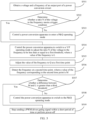
- FIG. 5 is a schematic flowchart of a method 500 for suppressing magnetic saturation of a transformer according to an embodiment of this application. The method is applied to a power conversion apparatus. As shown in FIG. 5 , the method 500 includes the following steps.
- S501 Obtain a voltage and a frequency of an output port of the power conversion apparatus.
- S502 Determine whether a ratio N of the voltage to the frequency meets a trigger condition.
- the power conversion apparatus obtains the voltage and the frequency of the output port of the power conversion apparatus, obtains the ratio N of the voltage to the frequency through calculation based on the obtained voltage and frequency, and determines whether the ratio N of the voltage to the frequency meets the trigger condition.
- S503 is performed.
- S504 is performed.
- the trigger condition includes that the ratio of the voltage to the frequency is greater than a second threshold.
- the power conversion apparatus may be a three-phase inverter.
- the inverter detects three line-to-line voltages of an output port of the inverter, performs phase-locked loop processing on the three line-to-line voltages to obtain a positive-order component and a frequency of the voltages, determines the positive-order component of the voltages as the voltage of the output port, and determines, as the frequency of the output port, a frequency obtained through the phase-locked loop processing.
- the power conversion apparatus may be a single-phase inverter.
- the inverter detects a phase voltage and a frequency of an output port of the inverter, and determines the phase voltage and the frequency as the voltage and the frequency of the output port.
- S503 Control the power conversion apparatus to enter a P&Q operating mode.
- the power conversion apparatus may control the power conversion apparatus to enter the P&Q operating mode.
- the power conversion apparatus may control the power conversion apparatus to enter the P&Q operating mode, to control active power and reactive power.
- the power conversion apparatus controls the power conversion apparatus to enter the P&Q operating mode.
- the power conversion apparatus is in a V/F operating mode before S503 is performed. In this case, when S503 is performed, the power conversion apparatus may switch from the V/F operating mode to the P&Q operating mode.
- the power conversion apparatus is already in the P&Q operating mode before S503 is performed. In this case, when S503 is performed, the power conversion apparatus may keep the power conversion apparatus in the P&Q operating mode.
- S504 Control the power conversion apparatus to switch to the V/F operating mode to adjust the ratio N of the voltage to the frequency to be less than or equal to a first threshold, where a value of the frequency is L.
- the power conversion apparatus may control the power conversion apparatus to switch from the P&Q operating mode to the V/F operating mode. In the V/F operating mode, the power conversion apparatus may adjust the voltage and/or the frequency, so that the ratio N of the voltage to the frequency is less than or equal to the first threshold.
- the power conversion apparatus may first determine adjustment target values of the voltage and the frequency, and then adjust the voltage to a first adjustment target value and adjust the frequency to a second adjustment target value.
- the first adjustment target value may be a moving average value of positive-order components of line-to-line voltages of the three-phase inverter within A mains frequency cycles before the trigger condition is met, where A is greater than or equal to 1, and is an integer.
- the second adjustment target value may be a moving average value of frequencies of the three-phase inverter within B mains frequency cycles before the trigger condition is met, where B is greater than or equal to 1, and is an integer. B may be equal to A, or may not be equal to A.
- the first adjustment target value and the second adjustment target value may be preset values.
- the first adjustment target value may be preset to 1.1 pu.
- a reference value corresponding to the first adjustment target value is a peak value of a rated phase voltage of a power grid
- the second adjustment target value may be a rated frequency of the power grid.
- the first adjustment target value when the power conversion apparatus 100 is the single-phase inverter, the first adjustment target value may be a moving average value of phase voltages of the single-phase inverter within C mains frequency cycles before the trigger condition is met, where C is greater than or equal to 1, and is an integer.
- the second adjustment target value may be a moving average value of frequencies of the single-phase inverter within D mains frequency cycles before the trigger condition is met, where D is greater than or equal to 1, and is an integer. D may be equal to C, or may not be equal to C.
- the first adjustment target value and the second adjustment target value may be preset values.
- the first adjustment target value may be 1.1 pu.
- a reference value corresponding to the first adjustment target value is a peak value of a rated phase voltage of a power grid
- the second adjustment target value may be a rated frequency of the power grid.
- the value of the frequency is L, where L is equal to the rated frequency of the power grid, and the method 500 further includes the following steps.
- S505 Adjust the value of the frequency to Q at a first time point, where Q is greater than L.
- S506 Detect the frequency at a second time point, where a value of the frequency corresponding to the second time point is M.
- S507 Determine whether a difference between M and L is greater than a third threshold.
- the ratio N of the voltage to the frequency may be less than or equal to the first threshold.
- the value of the frequency is L.
- the power conversion apparatus adjusts the value of the frequency to Q at the first time point, where Q is greater than L and Q is greater than the rated frequency of the power grid; and detects that the value of the frequency at the second time point is M. By determining whether the difference between M and L is greater than the third threshold, the power conversion apparatus determines whether the power grid is powered off.
- the power grid may not be powered off, and a reason why the ratio N of the voltage to the frequency is greater than the second threshold may be that the power grid is disturbed. In this case, S508 is performed. If the difference between M and L is greater than the third threshold, the power grid may be powered off, and consequently the ratio N of the voltage to the frequency is greater than the second threshold. In this case, S509 is performed.
- the third threshold may be a preset value.
- the third threshold is 0.5 Hz.
- S508 Control the power conversion apparatus to switch to the P&Q operating mode.
- the power conversion apparatus determines that the reason why the ratio N of the voltage to the frequency is greater than the second threshold may be that the power grid is disturbed, and may switch the power conversion apparatus from the V/F operating mode to the P&Q operating mode to control active power and reactive power.
- S509 Stop sending a PWM driver gating signal within a short period of time or perform power-off.
- the power conversion apparatus may stop sending the PWM driver gating signal within the short period of time or perform power-off to avoid islanding.
- the stopping sending a PWM driver gating signal within a short period of time or performing power-off in S509 includes: stopping sending the PWM driver gating signal within the short period of time.
- the method 500 further includes: performing power-off if detecting that the voltage is 0 when sending of the PWM driver gating signal stops within the short period of time.
- the power conversion apparatus may first stop sending the PWM driver gating signal within the short period of time, detect the voltage of the output port when sending of the PWM driver gating signal stops within the short period of time, and perform power-off if detecting that the voltage is 0.
- the trigger condition further includes that duration within which the ratio of the voltage to the frequency is greater than N is greater than or equal to a fourth threshold, that is, the trigger condition is that the ratio N of the voltage to the frequency is greater than the second threshold and the duration is greater than or equal to the fourth threshold.
- the value of the frequency is O.
- the method 500 further includes: performing low-pass filtering on the frequency.
- the power conversion apparatus may perform low-pass filtering processing on the frequency, and a value of a frequency obtained through the low-pass filtering processing is P.
- the trigger condition further includes that an absolute value of a difference between O and P is greater than the third threshold.
- the trigger condition is that the ratio N of the voltage to the frequency is greater than the second threshold and the absolute value of the difference between O and P is greater than the third threshold.
- the trigger condition is that the ratio of the voltage to the frequency is greater than N, the absolute value of the difference between O and P is greater than the third threshold, and the duration is greater than or equal to the fourth threshold.
- the power conversion apparatus can accurately determine whether the transformer runs in the magnetic saturation operating condition.
- the power conversion apparatus can switch an operating mode to the V/F operating mode to adjust the voltage and/or frequency. In this way, the transformer is relieved from the magnetic saturation operating condition, and occurrence of magnetic saturation of the transformer is suppressed.
- the power conversion apparatus can determine, by increasing the frequency, whether the power grid is actually powered off. When determining that the power grid is powered off, the power conversion apparatus can perform stop sending a PWM driver gating signal within a short period of time or perform power-off, to avoid islanding.
- a component may be but is not limited to a process that runs on a processor, a processor, an object, an executable file, an execution thread, a program, and/or a computer.
- a computing device and an application that runs on the computing device may be components.
- One or more components may reside within a process and/or an execution thread, and the component may be located on one computer and/or distributed between two or more computers.
- these components may be executed from various computer-readable media that store various data structures.
- the components may communicate by using a local and/or remote process and based on, for example, a signal having one or more data packets (for example, data from two components interacting with another component in a local system, a distributed system, and/or across a network such as the internet interacting with other systems by using the signal).
- a signal having one or more data packets (for example, data from two components interacting with another component in a local system, a distributed system, and/or across a network such as the internet interacting with other systems by using the signal).
- the disclosed system, apparatus, and method may be implemented in other manners.
- the described apparatus embodiment is merely an example.
- division into units is merely logical function division and may be other division during actual implementation.
- a plurality of units or components may be combined or integrated into another system, or some features may be ignored or not performed.
- the displayed or discussed mutual couplings or direct couplings or communication connections may be implemented through some interfaces.
- the indirect couplings or communication connections between the apparatuses or units may be implemented in electronic, mechanical, or other forms.
- the units described as separate parts may or may not be physically separate, and parts displayed as units may or may not be physical units, may be located in one position, or may be distributed on a plurality of network units. Some or all of the units may be selected based on actual requirements to achieve the objectives of the solutions of embodiments.
- functional units in embodiments of this application may be integrated into one processing unit, each of the units may exist alone physically, or two or more units are integrated into one unit.
- the functions When the functions are implemented in a form of a software functional unit and sold or used as an independent product, the functions may be stored in a computer-readable storage medium. Based on such an understanding, the technical solutions of this application essentially, or the part contributing to the conventional technology, or some of the technical solutions may be implemented in a form of a software product.
- the software product is stored in a storage medium, and includes several instructions for instructing a computer device (which may be a personal computer, a server, or a network device) to perform all or some of the steps of the methods described in embodiments of this application.
- the foregoing storage medium includes any medium that can store program code, for example, a USB flash drive, a removable hard disk, a read-only memory (read-only memory, ROM), a random access memory (random access memory, RAM), a magnetic disk, or an optical disc.
- a USB flash drive for example, a USB flash drive, a removable hard disk, a read-only memory (read-only memory, ROM), a random access memory (random access memory, RAM), a magnetic disk, or an optical disc.
Landscapes
- Engineering & Computer Science (AREA)
- Power Engineering (AREA)
- Inverter Devices (AREA)
Abstract
This application provides a method for suppressing magnetic saturation of a transformer and a power conversion apparatus. The power conversion apparatus includes a power conversion circuit and a controller. The power conversion circuit is configured to convert a direct current into an alternating current. The controller is configured to: obtain a voltage and a frequency of an output port of the power conversion circuit, and control, based on a ratio N of the voltage to the frequency, the power conversion apparatus to enter a P&Q operating mode or a V/F operating mode. In embodiments of this application, whether magnetic saturation occurs to the transformer is determined based on the ratio N of the voltage to the frequency, to control the transformer to enter the P&Q operating mode or the V/F operating mode. In this way, the transformer can operate in a normal operating condition, and is relieved from a magnetic saturation operating condition. This can avoid a phenomenon of a big current caused by magnetic saturation.
Description
- Embodiments of this application relate to the field of power technologies, and more specifically, to a method for suppressing magnetic saturation of a transformer and a power conversion apparatus.
- A new energy power generation system may generate a direct current by using solar energy, an energy storage system, and the like, convert the direct current into an alternating current by using a power conversion apparatus (for example, an inverter), and then output the alternating current to a power grid for use by the power grid. For the power conversion apparatus, an alternating current grid connection end may be connected to a power consuming load, and may also be connected to a transformer having a voltage boosting function. If a high-voltage side of the transformer is disconnected from the power grid, islanding occurs between the power conversion apparatus, the power consuming load, and a low-voltage side of the transformer. Islanding is apt to bring a safety risk to a power maintenance person and a power consuming device. Therefore, the power conversion apparatus is provided with an anti-islanding function. In an islanding state, a problem of an overcurrent on an alternating current side of the power conversion apparatus is a main factor that affects safe operation of the power conversion apparatus. When the transformer is magnetically saturated, an output current of the power conversion apparatus is likely to be an overcurrent. Therefore, how to suppress magnetic saturation of the transformer in the islanding state becomes one of technical problems that need to be urgently resolved.
- This application provides a method for suppressing magnetic saturation of a transformer and a power conversion apparatus. The power conversion apparatus may obtain a voltage and a frequency of an output port of the power conversion apparatus, and determine, based on a ratio N of the voltage to the frequency, whether magnetic saturation occurs to the transformer, to control the power conversion apparatus to enter a P&Q operating mode or a V/F operating mode. In this way, the transformer can operate in a normal operating condition, and is relieved from a magnetic saturation operating condition. This can avoid a phenomenon of a big current caused by magnetic saturation. According to a first aspect, a power conversion apparatus is provided. The power conversion apparatus includes a controller and a power conversion circuit. The power conversion circuit is configured to convert a direct current into an alternating current. An input port of the power conversion circuit is configured to connect to a direct current source. An output port of the power conversion circuit is connected to a power grid through a transformer. The controller is configured to: obtain a voltage and a frequency of the output port of the power conversion circuit, and control, based on a ratio N of the voltage to the frequency, the power conversion apparatus to switch to a P&Q operating mode or a V/F operating mode. The P&Q operating mode is a constant power operating mode, and is used to control active power and reactive power of the output port of the power conversion apparatus. The V/F operating mode is a constant voltage and constant frequency operating mode, and is used to control the voltage and the frequency of the output port of the power conversion apparatus.
- In embodiments of this application, by obtaining the voltage and the frequency of the output port of the power conversion apparatus, the controller may obtain the ratio N of the voltage to the frequency through calculation, and control an operating mode of the power conversion apparatus based on N. In this way, the transformer operates in a normal operating condition, and is relieved from a magnetic saturation operating condition. This can effectively avoid impact, on the power conversion apparatus, of a big current caused by magnetic saturation of the transformer.
- With reference to the first aspect, in a first possible implementation of the first aspect, the controller is specifically configured to: in response to meeting a trigger condition, control the power conversion apparatus to switch to the V/F operating mode, to adjust the ratio N of the voltage to the frequency to be less than or equal to a first threshold. The trigger condition includes that the ratio N of the voltage to the frequency is greater than a second threshold. The second threshold is greater than or equal to the first threshold.
- With reference to the first possible implementation of the first aspect, in a second possible implementation of the first aspect, when the ratio N of the voltage to the frequency is less than or equal to the first threshold, a value of the frequency is L. The controller is further configured to: adjust the value of the frequency to Q at a first time point, where Q is greater than L, and Q is greater than a rated frequency of the power grid; detect the frequency at a second time point, where a value of the frequency corresponding to the second time point is M; and in response to a case in which a difference between M and L is greater than a third threshold, stop sending a PWM driver gating signal within a short period of time or perform power-off; or in response to a case in which a difference between M and L is less than or equal to a third threshold, control the power conversion apparatus to switch to the P&Q operating mode.
- In embodiments of this application, after the ratio N of the voltage to the frequency is adjusted to be less than or equal to the first threshold, the frequency may be increased to determine whether the power grid is powered off. After it is determined that a reason why the ratio N of the voltage to the frequency is greater than the second threshold is power-off of the power grid, sending of a PWM driver gating signal stops within a short period of time or power-off is performed. This can eliminate a case in which the ratio N of the voltage to the frequency is mistakenly determined to be greater than the second threshold because the power grid is disturbed.
- With reference to the second possible implementation of the first aspect, in a third implementation of the first aspect, the controller is specifically configured to: in response to the case in which the difference between M and L is greater than the third threshold, stop sending the PWM driver gating signal within the short period of time. The controller is further configured to perform power-off in response to detecting that the voltage is 0 when sending of the PWM driver gating signal stops within the short period of time.
- In embodiments of this application, after power-off of the power grid is determined via the increase of the frequency sending of the PWM driver gating signal stops within the short period of time. When sending of the PWM driver gating signal stops within the short period of time, whether the power grid is powered off is further determined by detecting whether the voltage is 0. In this way, whether the power grid is powered off can be more accurately determined.
- With reference to the first implementation to the third implementation of the first aspect, in a fourth implementation of the first aspect, when the ratio N of the voltage to the frequency is greater than the second threshold, a value of the frequency is O. The controller is further configured to perform low-pass filtering processing on the frequency. A value of a frequency obtained through low-pass filtering processing is P. The trigger condition further includes that an absolute value of a difference between O and P is greater than the third threshold.
- In embodiments of this application, to prevent the power conversion apparatus from stopping sending a PWM driver gating signal or performing power-off in a high voltage ride-through state, whether the absolute value of difference between O and P is greater than the third threshold is introduced into the trigger condition to determine whether the power conversion apparatus is in the high voltage ride-through state. In this way, a conflict between high voltage ride-through and stopping of PWM driver gating signal sending or power-off can be avoided.
- With reference to the first implementation to the fourth implementation of the first aspect, in a fifth implementation of the first aspect, the trigger condition further includes that duration of the trigger condition is greater than or equal to a fourth threshold.
- With reference to the first implementation to the fifth implementation of the first aspect, in a sixth implementation of the first aspect, the power conversion apparatus is a three-phase inverter. The controller is specifically configured to: obtain three line-to-line voltages of an output port of the three-phase inverter, and perform phase-locked loop processing on the three line-to-line voltages to obtain the voltage and the frequency.
- With reference to the first implementation to the sixth implementation of the first aspect, in a seventh implementation of the first aspect, the power conversion apparatus further includes at least one circuit having a maximum power point tracking capability. The at least one circuit having the maximum power point tracking capability is configured to connect to a plurality of photovoltaic modules, and is configured to adjust output voltages of the plurality of photovoltaic modules, to track maximum power operating points of the plurality of photovoltaic modules during normal operation. An output end of the at least one circuit having the maximum power point tracking capability is connected to the input end of the power conversion circuit.
- According to a second aspect, a method for suppressing magnetic saturation of a transformer is provided. The method is applied to a power conversion apparatus. The method includes: obtaining a voltage and a frequency of an output port of the power conversion apparatus; and controlling, based on a ratio N of the voltage to the frequency, the power conversion apparatus to switch to a P&Q operating mode or a V/F operating mode. The P&Q operating mode is a constant power operating mode, and is used to control active power and reactive power of the output port of the power conversion apparatus. The V/F operating mode is a constant voltage and constant frequency operating mode, and is used to control the voltage and the frequency of the output port of the power conversion apparatus.
- In embodiments of this application, by obtaining the voltage and the frequency of the output port of the power conversion apparatus, the power conversion apparatus may obtain the ratio N of the voltage to the frequency through calculation, and control an operating mode of the power conversion apparatus based on N. In this way, the transformer operates in a normal operating condition, and is relieved from a magnetic saturation operating condition. This can effectively avoid impact, on the power conversion apparatus, of a big current caused by magnetic saturation of the transformer.
- With reference to the second aspect, in a first possible implementation of the second aspect, the controlling, based on a ratio N of the voltage to the frequency, the power conversion apparatus to enter a P&Q operating mode or a V/F operating mode includes: in response to meeting a trigger condition, controlling the power conversion apparatus to switch to the V/F operating mode, to adjust the ratio N of the voltage to the frequency to be less than or equal to a first threshold. The trigger condition includes that the ratio N of the voltage to the frequency is greater than a second threshold. The second threshold is greater than or equal to the first threshold.
- With reference to the first implementation of the second aspect, in a second implementation of the second aspect, when the ratio N of the voltage to the frequency is less than or equal to the first threshold, a value of the frequency is L. The method further includes: adjusting the value of the frequency to Q at a first time point, where Q is greater than L, and Q is greater than a rated frequency of a power grid; detecting the frequency at a second time point, where a value of the frequency corresponding to the second time point is M; and in response to a case in which a difference between M and L is greater than a third threshold, stopping sending a PWM driver gating signal within a short period of time or performing power-off; or in response to a case in which a difference between M and L is less than or equal to a third threshold, control the power conversion apparatus to switch to the P&Q operating mode.
- In embodiments of this application, after the ratio N of the voltage to the frequency is adjusted to be less than or equal to the first threshold, the frequency may be increased to determine whether the power grid is powered off. After it is determined that a reason why the ratio N of the voltage to the frequency is greater than the second threshold is power-off of the power grid, sending of a PWM driver gating signal stops within a short period of time or power-off is performed. This can eliminate a case in which the ratio N of the voltage to the frequency is mistakenly determined to be greater than the second threshold because the power grid is disturbed.
- With reference to the second implementation of the second aspect, in a third implementation of the second aspect, the stopping sending a PWM driver gating signal within a short period of time or performing power-off, in response to a case in which a difference between M and L is greater than a third threshold includes: in response to the case in which the difference between M and L is greater than the third threshold, stopping sending the PWM driver gating signal within the short period of time. The method further includes: performing power-off in response to detecting that the voltage changes to 0 when sending of the PWM driver gating signal stops within the short period of time.
- In embodiments of this application, after power-off of the power grid is determined via the increase of the frequency, sending of the PWM driver gating signal stops within the short period of time. When sending of the PWM driver gating signal stops within the short period of time, whether the power grid is powered off is further determined by detecting whether the voltage is 0. In this way, whether the power grid is powered off can be more accurately determined.
- With reference to the first implementation to the third implementation of the second aspect, in a fourth implementation of the second aspect, when the ratio N of the voltage to the frequency is greater than the second threshold, a value of the frequency is O. The method further includes: performing low-pass filtering processing on the frequency. A value of a frequency obtained through low-pass filtering processing is P. The trigger condition further includes that an absolute value of a difference between O and P is greater than the third threshold.
- In embodiments of this application, to prevent the power conversion apparatus from stopping sending a PWM driver gating signal or performing power-off in a high voltage ride-through state, whether the absolute value of difference between O and P is greater than the third threshold is introduced into the trigger condition to determine whether the power conversion apparatus is in the high voltage ride-through state. In this way, a conflict between high voltage ride-through and stopping of PWM driver gating signal sending or power-off can be avoided.
- With reference to the first implementation to the fourth implementation of the second aspect, in a fifth implementation of the second aspect, the trigger condition further includes that duration of the trigger condition is greater than or equal to a fourth threshold.
- According to a third aspect, a power system is provided. The power system includes a direct current source, a power grid, and the power conversion apparatus according to any one of the first aspect and the implementations of the first aspect. The direct current source is connected to an input port of the power conversion apparatus. The input port of the power conversion apparatus is connected to the power grid. The direct current source is configured to generate a direct current. The power conversion apparatus is configured to: convert the direct current into an alternating current, and input the obtained alternating current to the power grid.
-
-
FIG. 1 is a schematic block diagram of a power conversion apparatus according to an embodiment of this application; -
FIG. 2 is a schematic diagram of a power system according to an embodiment of this application; -
FIG. 3 is a schematic diagram of another power system according to an embodiment of this application; -
FIG. 4 is a schematic diagram of a voltage change corresponding to a case in which islanding occurs to a power conversion apparatus; and -
FIG. 5 is a schematic flowchart of a method for suppressing magnetic saturation of a transformer according to an embodiment of this application. - The following describes the technical solutions in embodiments of this application with reference to the accompanying drawings.
-
FIG. 1 is a schematic block diagram of a power conversion apparatus according to an embodiment of this application. The power conversion apparatus 100 shown inFIG. 1 includes apower conversion circuit 111 and acontroller 112. An input port of thepower conversion circuit 111 is configured to connect to a direct current source. An output port of thepower conversion circuit 111 is connected to a power grid through a transformer. Thepower conversion circuit 111 is configured to convert a direct current into an alternating current. - For example, the power conversion apparatus may be an inverter or a power conversion system (power conversion system, PCS).
- Optionally, in some embodiments, a power consuming load may be further connected between the output port of the power conversion apparatus 100 and the power grid. The power conversion apparatus 100 may convert the direct current into the alternating current by using the
power conversion circuit 111, and transmit, to the power consuming load, an alternating current obtained through processing performed by the transformer, so that the power consuming load can operate normally. -
FIG. 2 is a schematic diagram of a power system according to an embodiment of this application. As shown inFIG. 2 , the power system includes a direct current source, a power conversion apparatus, a transformer, and a power grid. One end of the power conversion apparatus is connected to the direct current source, and the other end is connected to the power grid through the transformer. When both the power grid and the power conversion apparatus run normally, the power conversion apparatus may convert, into an alternating current, a direct current input by the direct current source, and transmit the alternating current to the power grid. The direct current source may be a photovoltaic array, a wind-generated direct current source, an energy storage system, or the like. In the power system shown inFIG. 2 , the power conversion apparatus may be an inverter. If the direct current source is a photovoltaic array, the inverter is correspondingly a photovoltaic inverter. To rectify a direct current generated by a photovoltaic module, a rectifier may be further disposed in the power system. The rectifier is connected between an output port of the photovoltaic module and an input port of the photovoltaic inverter. The rectifier is configured to: rectify the direct current generated by the photovoltaic module, and input a direct current obtained after rectification into the photovoltaic inverter. -
FIG. 3 is a schematic diagram of another power system according to an embodiment of this application. As shown inFIG. 3 , the power system includes a plurality of direct current sources and a plurality of power conversion apparatuses. The plurality of power conversion apparatuses are connected in parallel and then are connected to a power grid through a transformer. When the power grid and the plurality of power conversion apparatuses run normally, direct currents input by the plurality of direct current sources are converted into alternating currents by using power conversion apparatuses corresponding to the plurality of direct current sources, and the alternating currents are transmitted to the power grid. In the power system shown inFIG. 3 , the plurality of direct current sources may be direct current sources of a same type, or may be direct current sources of different types. A type of each direct current source matches a type of a power conversion apparatus corresponding to the direct current source. - Currently, when determining that islanding occurs, the power conversion apparatus may stop sending a PWM driver gating signal or perform power-off, to indirectly prevent the transformer from being in a magnetic saturation running state for a long time. Specifically, as shown in
FIG. 4 , the power conversion apparatus may detect a voltage of an output port to determine whether islanding occurs. After the voltage of the output port of the power conversion apparatus exceeds a threshold O V and duration reaches Tdi, the power conversion apparatus may perform overvoltage protection such as stopping of PWM driver gating signal sending or power-off. - However, the foregoing solution is defected by the following disadvantages: (1) If the transformer generates a big current due to magnetic saturation within Tdi, the power conversion apparatus does not perform any protection measure, and consequently the power conversion apparatus may be damaged. (2) A PWM driver gating signal sending stopping or power-off function of the power conversion apparatus conflicts with a high voltage ride-through function. If the power conversion apparatus is in a high voltage ride-through state, the power conversion apparatus cannot stop sending a PWM driver gating signal or perform power-off, and the transformer may be in a magnetic saturation state for a long time, and then may generate the big current to cause damage to the power conversion apparatus. (3) If a ratio of the voltage to a frequency of the output port of the power conversion apparatus is excessively large, the transformer may also be in the magnetic saturation state. As a result, if only the voltage of the output port of the power conversion apparatus is detected, a corresponding operating condition obtained when magnetic saturation occurs to the transformer cannot be fully covered.
- On the basis of this, embodiments of this application provide a power conversion apparatus and a method for suppressing magnetic saturation of a transformer, so that whether the transformer is in a magnetic saturation operating condition can be accurately and quickly determined, and a voltage and/or a frequency of an output port can be adjusted to enable the transformer to be relieved from the magnetic saturation operating condition.
- Before embodiments of this application are described, several concepts that may be used in embodiments of this application are first described.
- A P&Q operating mode is also referred to as a constant power operating mode. In this operating mode, the
controller 112 may control active power and reactive power, that are output by the power conversion apparatus 100, to be equal to reference power of the power conversion apparatus 100. - A V/F operating mode is also referred to as a constant voltage and constant frequency operating mode. In this operating mode, adjustment target values of the voltage and the frequency of the output port may be set, the voltage is controlled, based on the adjustment target value of the voltage, to make a value of the voltage equal to the adjustment target value of the voltage, the frequency is controlled, based on the adjustment target value of the frequency, to make a value of the frequency equal to the adjustment target value of the frequency, and output active power and reactive power are determined by a load. The V/F operating mode is commonly used in an islanding mode. In other words, in this operating mode, for different operating conditions, the power conversion apparatus 100 may control the values of the voltage and the frequency of the output port of the power conversion apparatus 100 to be respectively equal to the adjustment target value of the voltage and the adjustment target value of the frequency. The adjustment target value of the voltage and the adjustment target value of the frequency may be changed.
- It can be learned from
FIG. 1 that the power conversion apparatus 100 embodiments of this application includes thepower conversion circuit 111 and thecontroller 112. Thecontroller 112 is configured to obtain the voltage and the frequency of the output port of the power conversion apparatus 100. Thecontroller 112 is further configured to control, based on a ratio N of the voltage to the frequency of the output port, the power conversion apparatus 100 to enter the P&Q operating mode or the V/F operating mode. - In embodiments of this application, by obtaining the voltage and the frequency of the output port of the power conversion apparatus 100, the
controller 112 may obtain the ratio N of the voltage to the frequency through calculation, and control an operating mode of the power conversion apparatus based on N. In this way, the transformer operates in a normal operating condition, and is relieved from a magnetic saturation operating condition. This can effectively avoid impact, on the power conversion apparatus, of a big current caused by magnetic saturation of the transformer. Optionally, in some embodiments, when determining that a trigger condition is met, thecontroller 112 controls the power conversion apparatus 100 to switch to the V/F operating mode. In the V/F operating mode, thecontroller 112 may adjust the voltage and/or the frequency, so that the ratio of the voltage to the frequency is less than or equal to a first threshold. The trigger condition includes that the ratio of the voltage to the frequency is greater than a second threshold. The second threshold may be equal to the first threshold, or may be greater than the first threshold. - It should be understood that the first threshold may be a preset value. For example, the first threshold is 1.1 per unit (per unit, pu). A reference value corresponding to the first threshold is a ratio of a peak value of a rated phase voltage of the power grid to a rated frequency of the power grid. In other words, the ratio of the peak value of the rated phase voltage of the power grid to the rated frequency of the power grid is 1 pu. Similarly, the second threshold may be a preset value. For example, the second threshold may be 1.2 pu. A reference value corresponding to the second threshold is a ratio of the peak value of the rated phase voltage of the power grid to the rated frequency of the power grid.
- Specifically, in an embodiment of this application, the
controller 112 determines, based on whether the ratio N of the voltage to the frequency of the output port of the power conversion apparatus 100 is greater than the second threshold, whether the transformer is in a magnetic saturation operating condition. When the ratio N of the voltage to the frequency is greater than the second threshold, thecontroller 112 determines that the transformer is in the magnetic saturation operating condition, and thecontroller 112 may switch the operating mode of the power conversion apparatus 100 from the P&Q operating mode to the V/F operating mode. In the V/F operating mode, thecontroller 112 may adjust the voltage and/or the frequency, so that the ratio of the voltage to the frequency is less than or equal to the first threshold. The first threshold corresponds to a non-magnetic saturation operating condition. In this way, the transformer is relieved from the magnetic saturation operating condition. - Optionally, in some embodiments, the power conversion apparatus 100 may be a three-phase inverter. The
controller 112 may obtain three line-to-line voltages of an output port of the three-phase inverter. The three line-to-line voltages are respectively Uab, Ubc, and Uca. Thecontroller 112 performs phase-locked loop processing on the three line-to-line voltages to obtain a positive-order component (which may also be referred to as a positive-order voltage) and a frequency of the line-to-line voltages. Thecontroller 112 uses, as a voltage and a frequency of the output port, the positive-order voltage and the frequency that are obtained through phase-locked loop processing. - It should be noted that a phase-locked loop method used by the
controller 112 is not limited in embodiments of this application, and there may be the following several examples. - For example, the
controller 112 performs phase-locked loop processing on the foregoing three line-to-line voltages through a phase-locked loop circuit, to obtain the positive-order component and the frequency of the line-to-line voltages. - For example, the
controller 112 performs phase-locked loop processing on the foregoing three line-to-line voltages based on a software phase-locked loop algorithm, to obtain the positive-order component and the frequency of the line-to-line voltages. - It should be further noted that a method for detecting the line-to-line voltage of the output port of the three-phase inverter by the
controller 112 is not limited in embodiments of this application, and there may be the following several examples. - For example, the
controller 112 performs differential sampling by using a resistor and an operational amplifier, to obtain the line-to-line voltages of the output port. - For example, the
controller 112 performs sampling by using a linear opto-isolator, to obtain the line-to-line voltages of the output port. - For example, the
controller 112 performs sampling by using a Hall sensor, to obtain the line-to-line voltages of the output port. - Optionally, in some embodiments, the power conversion apparatus 100 may be a three-phase inverter. The
controller 112 may obtain three line-to-line voltages of an output port of the three-phase inverter. The three line-to-line voltages are respectively Uab, Ubc, and Uca. Thecontroller 112 calculates an average value of the three line-to-line voltages based on the three line-to-line voltages, and determines the average value of the three line-to-line voltages as a voltage of the output port of the three-phase inverter. In this embodiment, thecontroller 112 may directly obtain a frequency of the output port of the three-phase inverter. For example, thecontroller 112 may detect the frequency of the output port of the three-phase inverter by using a zero-crossing detection circuit. - Optionally, in some embodiments, the power conversion apparatus 100 may be a single-phase inverter. The
controller 112 may obtain a phase voltage of an output port of the single-phase inverter, determine the phase voltage as a voltage of the output port of the single-phase inverter, and perform phase-locked loop processing on the phase voltage to determine the frequency. Alternatively, thecontroller 112 may directly obtain the frequency of the output port of the single-phase inverter according to a method, for example, a zero-crossing detection circuit. - When determining that the trigger condition is met, the
controller 112 switches the power conversion apparatus to the V/F operating mode, and then, may adjust the voltage and/or the frequency, so that the ratio N of the voltage to the frequency is less than or equal to the first threshold. When adjusting the voltage and/or the frequency, thecontroller 112 may first determine adjustment target values of the voltage and the frequency, and then adjust the voltage to the adjustment target value of the voltage and adjust the frequency to the adjustment target value of the frequency. In the following, the adjustment target value of the voltage is referred to as a first adjustment target value, and the adjustment target value of the frequency is referred to as a second adjustment target value. - When the power conversion apparatus 100 is the three-phase inverter and the voltage is the positive-order component of the line-to-line voltages, the first adjustment target value may be a moving average value of positive-order components of line-to-line voltages of the three-phase inverter within A mains frequency cycles before the trigger condition is met, where A is greater than or equal to 1, and is an integer. Similarly, the second adjustment target value may be a moving average value of frequencies of the three-phase inverter within B mains frequency cycles before the trigger condition is met, where B is greater than or equal to 1, and is an integer. B may be equal to A, or may not be equal to A.
- Further, when a ratio of the moving average value of the positive-order components of the line-to-line voltages within the A mains frequency cycles to the moving average value of the frequencies within the B mains frequency cycles is greater than the second threshold, the first adjustment target value and the second adjustment target value may be the preset values. For example, the first adjustment target value may be preset to 1.1 pu. The reference value corresponding to the first adjustment target value is the peak value of the rated phase voltage of the power grid, and the second adjustment target value may be the rated frequency of the power grid.
- When the power conversion apparatus 100 is the single-phase inverter, the first adjustment target value may be a moving average value of phase voltages of the single-phase inverter within C mains frequency cycles before the trigger condition is met, where C is greater than or equal to 1, and is an integer. Similarly, the second adjustment target value may be a moving average value of frequencies of the single-phase inverter within D mains frequency cycles before the trigger condition is met, where D is greater than or equal to 1, and is an integer. D may be equal to C, or may not be equal to C.
- Further, when a ratio of the moving average value of the phase voltages within the C mains frequency cycles to the moving average value of the frequencies within the D mains frequency cycles is greater than the second threshold, the first adjustment target value and the second adjustment target value may be the preset values. For example, the first adjustment target value may be 1.1 pu. The reference value corresponding to the first adjustment target value is the peak value of the rated phase voltage of the power grid, and the second adjustment target value may be the rated frequency of the power grid.
- It should be noted that a method for adjusting the voltage and/or the frequency by the
controller 112 is not limited in embodiments of this application. For example, thecontroller 112 may adjust the voltage and/or the frequency according to a method, for example, a current loop control method or a voltage loop control method. - For example, the
controller 112 may adjust the voltage and/or the frequency by using the current loop control method. Thecontroller 112 includes a pulse-width modulation (pulse-width modulation, PWM) circuit (not shown inFIG. 3 ). After determining the first adjustment target value and the second adjustment target value, thecontroller 112 may determine a current reference value based on the first adjustment target value and the second adjustment target value, and output a modulated wave to the PWM circuit through current loop control. The PWM circuit may adjust the voltage and/or the frequency based on the modulated wave. - Optionally, in some embodiments, after the
controller 112 adjusts the voltage and/or the frequency, so that the ratio N of the voltage to the frequency is less than the first threshold, a value of the frequency is L. Thecontroller 112 may further adjust the value of the frequency to Q at a first time point, where Q is greater than L and Q is greater than the rated frequency of the power grid, and detect the frequency at a second time point, where a value of the frequency corresponding to the second time point is M. When detecting that a difference between M and L is greater than a third threshold, thecontroller 112 stops sending a PWM driver gating signal within a short period of time or performs power-off, or when detecting that a difference between M and L is less than or equal to a third threshold, thecontroller 112 controls the power conversion apparatus to switch to the P&Q operating mode. - Specifically, the power grid may be powered off or disturbed and consequently the ratio N of the voltage to the frequency is greater than the second threshold. To further determine a reason why the ratio N of the voltage to the frequency is greater than the second threshold, whether the power grid is actually powered off may be detected. In embodiments of this application, the frequency may be adjusted to Q at the first time point. Q is greater than L. A difference between Q and L is greater than the third threshold. The value of the frequency measured at the second time point is M. When the difference between M and L is greater than the third threshold, the
controller 112 may determine that the reason why the ratio N of the voltage to the frequency is greater than the second threshold may be that the power grid is actually powered off, and may stop sending a PWM driver gating signal within a short period of time or perform power-off. When the difference between M and L is less than or equal to the third threshold, thecontroller 112 may determine that the reason why the ratio N of the voltage to the frequency is greater than the second threshold may be that the power grid is disturbed, and control the power conversion apparatus to switch to the P&Q operating mode. When the power grid is not powered off, even if thecontroller 112 increases the value of the frequency to Q at the first time point, thecontroller 112 cannot successfully keep the value of the frequency unchanged at Q because of a clamping effect of the power grid and because Q is greater than the rated frequency of the power grid. In other words, the value of the frequency falls back. Therefore, thecontroller 112 may detect the frequency at the second time point. The value of the frequency at the second time point is M. If the difference between M and L is less than or equal to the third threshold, it may be considered that the power grid is not powered off. On the contrary, if a difference between M and L is greater than a third threshold, it may be considered that the power grid is actually powered off. - It should be understood that the third threshold may be a preset value. For example, the third threshold is 0.5 Hz.
- Further, in some embodiments, when detecting that the difference between M and L is greater than the third threshold, the
controller 112 stops sending a PWM driver gating signal within a short period of time. If detecting that the voltage is 0 when sending of the PWM driver gating signal stops within the short period of time, thecontroller 112 may perform power-off. - When the
controller 112 stops sending the PWM driver gating signal within the short period of time, if the power grid is actually powered off and the voltage is 0, thecontroller 112 may perform power-off. - Optionally, in some embodiments, when the ratio N of the voltage to the frequency is greater than the second threshold, the value of the frequency is O. The
controller 112 may further perform low-pass filtering processing on the frequency. A value of a frequency obtained through low-pass filtering processing is P. The trigger condition further includes that an absolute value of a difference between O and P is greater than the third threshold. In other words, in this embodiment, when the ratio N of the voltage to the frequency is greater than the second threshold and the absolute value of the difference between O and P is greater than the third threshold, thecontroller 112 controls the power conversion apparatus 100 to switch to the V/F operating mode. - It should be noted that, in embodiments of this application, a time constant for performing low-pass filtering processing may not be limited. For example, the time constant may be


- It should be further noted that a low-pass filtering method is not limited in embodiments of this application, and there may be the following several examples.
- For example, the
controller 112 may perform low-pass filtering processing on the frequency through a low-pass filter circuit. - For example, the
controller 112 may perform low-pass filtering processing on the frequency based on a software low-pass filtering algorithm. - In embodiments of this application, to prevent the power conversion apparatus from stopping sending a PWM driver gating signal or performing power-off in a high voltage ride-through state, whether the absolute value of difference between O and P is greater than the third threshold is introduced into the trigger condition to determine whether the power conversion apparatus is in the high voltage ride-through state. In this way, a conflict between high voltage ride-through and stopping of PWM driver gating signal sending or power-off can be avoided.
- Optionally, in some embodiments, the trigger condition further includes that duration of the trigger condition is greater than or equal to a fourth threshold.
- For example, the trigger condition may be that the ratio N of the voltage to the frequency is greater than the second threshold and the duration is greater than or equal to the fourth threshold.
- For another example, the trigger condition may be that the ratio N of the voltage to the frequency is greater than the second threshold, an absolute value of a difference between the frequency and the frequency obtained through low-pass filtering processing is greater than the third threshold, and the duration is greater than or equal to the fourth threshold.
- It should be understood that the fourth threshold may be a preset value. For example, the fourth threshold is three mains frequency cycles.
- Optionally, in some embodiments, the power conversion apparatus 100 further includes at least one circuit having a maximum power point tracking capability. The at least one circuit having the maximum power point tracking capability is used for maximum power point tracking (maximum power point tracking, MPPT). The at least one circuit having the maximum power point tracking capability is configured to: connect to a photovoltaic module, and adjust an output voltage of the photovoltaic module, to track a maximum power operating point of the photovoltaic module during normal operation. An output end of the at least one circuit having the maximum power point tracking capability is connected to the input end of the
power conversion circuit 111. - It should be understood that the photovoltaic module is a component that directly converts solar energy into electric energy through a photovoltaic (photovoltaic) effect produced by a semiconductor material in a lighting condition. The photovoltaic module may also be referred to as a photovoltaic array, a solar panel, or the like. This is not limited in embodiments of this application.
-
FIG. 5 is a schematic flowchart of a method 500 for suppressing magnetic saturation of a transformer according to an embodiment of this application. The method is applied to a power conversion apparatus. As shown inFIG. 5 , the method 500 includes the following steps. - S501: Obtain a voltage and a frequency of an output port of the power conversion apparatus.
- S502: Determine whether a ratio N of the voltage to the frequency meets a trigger condition.
- Specifically, the power conversion apparatus obtains the voltage and the frequency of the output port of the power conversion apparatus, obtains the ratio N of the voltage to the frequency through calculation based on the obtained voltage and frequency, and determines whether the ratio N of the voltage to the frequency meets the trigger condition. When the trigger condition is not met, S503 is performed. When the trigger condition is met, S504 is performed. Optionally, in some embodiments, the trigger condition includes that the ratio of the voltage to the frequency is greater than a second threshold.
- Optionally, in some embodiments, the power conversion apparatus may be a three-phase inverter. The inverter detects three line-to-line voltages of an output port of the inverter, performs phase-locked loop processing on the three line-to-line voltages to obtain a positive-order component and a frequency of the voltages, determines the positive-order component of the voltages as the voltage of the output port, and determines, as the frequency of the output port, a frequency obtained through the phase-locked loop processing.
- Optionally, in some embodiments, the power conversion apparatus may be a single-phase inverter. The inverter detects a phase voltage and a frequency of an output port of the inverter, and determines the phase voltage and the frequency as the voltage and the frequency of the output port.
- S503: Control the power conversion apparatus to enter a P&Q operating mode.
- When determining that the ratio N of the voltage to the frequency is less than or equal to the second threshold, the power conversion apparatus may control the power conversion apparatus to enter the P&Q operating mode. In other words, when determining that the transformer is in a non-magnetic saturation operating condition, the power conversion apparatus may control the power conversion apparatus to enter the P&Q operating mode, to control active power and reactive power. There may be the following several possible implementations in which the power conversion apparatus controls the power conversion apparatus to enter the P&Q operating mode.
- In a possible implementation, the power conversion apparatus is in a V/F operating mode before S503 is performed. In this case, when S503 is performed, the power conversion apparatus may switch from the V/F operating mode to the P&Q operating mode.
- In a possible implementation, the power conversion apparatus is already in the P&Q operating mode before S503 is performed. In this case, when S503 is performed, the power conversion apparatus may keep the power conversion apparatus in the P&Q operating mode.
- S504: Control the power conversion apparatus to switch to the V/F operating mode to adjust the ratio N of the voltage to the frequency to be less than or equal to a first threshold, where a value of the frequency is L.
- When determining that the ratio N of the voltage to the frequency is greater than the second threshold, the power conversion apparatus may control the power conversion apparatus to switch from the P&Q operating mode to the V/F operating mode. In the V/F operating mode, the power conversion apparatus may adjust the voltage and/or the frequency, so that the ratio N of the voltage to the frequency is less than or equal to the first threshold.
- It should be understood that, for descriptions of the first threshold and the second threshold, refer to the foregoing descriptions. For brevity, details are not described herein again.
- When adjusting the voltage and/or the frequency, the power conversion apparatus may first determine adjustment target values of the voltage and the frequency, and then adjust the voltage to a first adjustment target value and adjust the frequency to a second adjustment target value.
- Optionally, in some embodiments, when the power conversion apparatus 100 is the three-phase inverter and the voltage is a positive-order component of line-to-line voltages, the first adjustment target value may be a moving average value of positive-order components of line-to-line voltages of the three-phase inverter within A mains frequency cycles before the trigger condition is met, where A is greater than or equal to 1, and is an integer. Similarly, the second adjustment target value may be a moving average value of frequencies of the three-phase inverter within B mains frequency cycles before the trigger condition is met, where B is greater than or equal to 1, and is an integer. B may be equal to A, or may not be equal to A.
- Further, when a ratio of the moving average value of the positive-order components of the line-to-line voltages within the A mains frequency cycles to the moving average value of the frequencies within the B mains frequency cycles is greater than the second threshold, the first adjustment target value and the second adjustment target value may be preset values. For example, the first adjustment target value may be preset to 1.1 pu. A reference value corresponding to the first adjustment target value is a peak value of a rated phase voltage of a power grid, and the second adjustment target value may be a rated frequency of the power grid.
- Optionally, in some embodiments, when the power conversion apparatus 100 is the single-phase inverter, the first adjustment target value may be a moving average value of phase voltages of the single-phase inverter within C mains frequency cycles before the trigger condition is met, where C is greater than or equal to 1, and is an integer. Similarly, the second adjustment target value may be a moving average value of frequencies of the single-phase inverter within D mains frequency cycles before the trigger condition is met, where D is greater than or equal to 1, and is an integer. D may be equal to C, or may not be equal to C.
- Further, when a ratio of the moving average value of the phase voltages within the C mains frequency cycles to the moving average value of the frequencies within the D mains frequency cycles is greater than the second threshold, the first adjustment target value and the second adjustment target value may be preset values. For example, the first adjustment target value may be 1.1 pu. A reference value corresponding to the first adjustment target value is a peak value of a rated phase voltage of a power grid, and the second adjustment target value may be a rated frequency of the power grid.
- Optionally, in some embodiments, after S504 is performed, the value of the frequency is L, where L is equal to the rated frequency of the power grid, and the method 500 further includes the following steps.
- S505: Adjust the value of the frequency to Q at a first time point, where Q is greater than L.
- S506: Detect the frequency at a second time point, where a value of the frequency corresponding to the second time point is M.
- S507: Determine whether a difference between M and L is greater than a third threshold.
- Specifically, after the power conversion apparatus switches to the V/F operating mode, the ratio N of the voltage to the frequency may be less than or equal to the first threshold. In this case, the value of the frequency is L. To further determine whether the power grid is actually powered off, the power conversion apparatus adjusts the value of the frequency to Q at the first time point, where Q is greater than L and Q is greater than the rated frequency of the power grid; and detects that the value of the frequency at the second time point is M. By determining whether the difference between M and L is greater than the third threshold, the power conversion apparatus determines whether the power grid is powered off. If the difference between M and L is less than or equal to the third threshold, the power grid may not be powered off, and a reason why the ratio N of the voltage to the frequency is greater than the second threshold may be that the power grid is disturbed. In this case, S508 is performed. If the difference between M and L is greater than the third threshold, the power grid may be powered off, and consequently the ratio N of the voltage to the frequency is greater than the second threshold. In this case, S509 is performed.
- The third threshold may be a preset value. For example, the third threshold is 0.5 Hz.
- S508: Control the power conversion apparatus to switch to the P&Q operating mode.
- Specifically, the power conversion apparatus determines that the reason why the ratio N of the voltage to the frequency is greater than the second threshold may be that the power grid is disturbed, and may switch the power conversion apparatus from the V/F operating mode to the P&Q operating mode to control active power and reactive power. S509: Stop sending a PWM driver gating signal within a short period of time or perform power-off.
- Specifically, if the power conversion apparatus determines that the reason why the ratio N of the voltage to the frequency is greater than the second threshold may be that the power grid is powered off, the power conversion apparatus may stop sending the PWM driver gating signal within the short period of time or perform power-off to avoid islanding.
- Optionally, in some embodiments, the stopping sending a PWM driver gating signal within a short period of time or performing power-off in S509 includes:
stopping sending the PWM driver gating signal within the short period of time. The method 500 further includes:
performing power-off if detecting that the voltage is 0 when sending of the PWM driver gating signal stops within the short period of time. - Specifically, when determining that the difference between M and L is greater than the third threshold, the power conversion apparatus may first stop sending the PWM driver gating signal within the short period of time, detect the voltage of the output port when sending of the PWM driver gating signal stops within the short period of time, and perform power-off if detecting that the voltage is 0.
- Optionally, in some embodiments, the trigger condition further includes that duration within which the ratio of the voltage to the frequency is greater than N is greater than or equal to a fourth threshold, that is, the trigger condition is that the ratio N of the voltage to the frequency is greater than the second threshold and the duration is greater than or equal to the fourth threshold.
- Optionally, in some embodiments, when the ratio N of the voltage to the frequency is greater than the second threshold, the value of the frequency is O. The method 500 further includes:
performing low-pass filtering on the frequency. - The power conversion apparatus may perform low-pass filtering processing on the frequency, and a value of a frequency obtained through the low-pass filtering processing is P. In this embodiment, the trigger condition further includes that an absolute value of a difference between O and P is greater than the third threshold. In other words, the trigger condition is that the ratio N of the voltage to the frequency is greater than the second threshold and the absolute value of the difference between O and P is greater than the third threshold.
- Optionally, in some embodiments, the trigger condition is that the ratio of the voltage to the frequency is greater than N, the absolute value of the difference between O and P is greater than the third threshold, and the duration is greater than or equal to the fourth threshold.
- Based on the foregoing technical solutions, the power conversion apparatus can accurately determine whether the transformer runs in the magnetic saturation operating condition. When determining that the transformer runs in the magnetic saturation operating condition, the power conversion apparatus can switch an operating mode to the V/F operating mode to adjust the voltage and/or frequency. In this way, the transformer is relieved from the magnetic saturation operating condition, and occurrence of magnetic saturation of the transformer is suppressed. In addition, the power conversion apparatus can determine, by increasing the frequency, whether the power grid is actually powered off. When determining that the power grid is powered off, the power conversion apparatus can perform stop sending a PWM driver gating signal within a short period of time or perform power-off, to avoid islanding. Terminologies such as "component", "module", and "system" used in this specification indicates computer-related entities, hardware, firmware, a combination of hardware and software, software, or software being executed. For example, a component may be but is not limited to a process that runs on a processor, a processor, an object, an executable file, an execution thread, a program, and/or a computer. As illustrated by using figures, both a computing device and an application that runs on the computing device may be components. One or more components may reside within a process and/or an execution thread, and the component may be located on one computer and/or distributed between two or more computers. In addition, these components may be executed from various computer-readable media that store various data structures. For example, the components may communicate by using a local and/or remote process and based on, for example, a signal having one or more data packets (for example, data from two components interacting with another component in a local system, a distributed system, and/or across a network such as the internet interacting with other systems by using the signal).
- A person of ordinary skill in the art may be aware that, in combination with the examples described in embodiments disclosed in this specification, units and algorithm steps may be implemented by electronic hardware or a combination of computer software and electronic hardware. Whether these functions are performed by hardware or software depends on particular applications and design constraint conditions of the technical solutions. A person skilled in the art may use different methods to implement the described functions for each particular application, but it should not be considered that the implementation goes beyond the scope of this application.
- It may be clearly understood by a person skilled in the art that, for the purpose of convenient and brief description, for a detailed operating process of the foregoing system, apparatus, and unit, refer to a corresponding process in the foregoing method embodiments. Details are not described herein again.
- In the several embodiments provided in this application, it should be understood that the disclosed system, apparatus, and method may be implemented in other manners. For example, the described apparatus embodiment is merely an example. For example, division into units is merely logical function division and may be other division during actual implementation. For example, a plurality of units or components may be combined or integrated into another system, or some features may be ignored or not performed. In addition, the displayed or discussed mutual couplings or direct couplings or communication connections may be implemented through some interfaces. The indirect couplings or communication connections between the apparatuses or units may be implemented in electronic, mechanical, or other forms.
- The units described as separate parts may or may not be physically separate, and parts displayed as units may or may not be physical units, may be located in one position, or may be distributed on a plurality of network units. Some or all of the units may be selected based on actual requirements to achieve the objectives of the solutions of embodiments. In addition, functional units in embodiments of this application may be integrated into one processing unit, each of the units may exist alone physically, or two or more units are integrated into one unit.
- When the functions are implemented in a form of a software functional unit and sold or used as an independent product, the functions may be stored in a computer-readable storage medium. Based on such an understanding, the technical solutions of this application essentially, or the part contributing to the conventional technology, or some of the technical solutions may be implemented in a form of a software product. The software product is stored in a storage medium, and includes several instructions for instructing a computer device (which may be a personal computer, a server, or a network device) to perform all or some of the steps of the methods described in embodiments of this application. The foregoing storage medium includes any medium that can store program code, for example, a USB flash drive, a removable hard disk, a read-only memory (read-only memory, ROM), a random access memory (random access memory, RAM), a magnetic disk, or an optical disc.
- The foregoing descriptions are merely specific implementations of this application, but are not intended to limit the protection scope of this application. Any variation or replacement readily figured out by a person skilled in the art within the technical scope disclosed in this application shall fall within the protection scope of this application. Therefore, the protection scope of this application shall be subject to the protection scope of the claims.
Claims (15)
- A power conversion apparatus, wherein the power conversion apparatus comprises a controller and a power conversion circuit;an input port of the power conversion circuit is configured to connect to a direct current source, and an output port of the power conversion circuit is connected to a power grid through a transformer; andthe controller is configured to: obtain a voltage and a frequency of the output port of the power conversion circuit, and control, based on a ratio N of the voltage to the frequency, the power conversion apparatus to switch to a P&Q operating mode or a V/F operating mode, wherein the P&Q operating mode is a constant power operating mode, and is used to control active power and reactive power of the output port of the power conversion apparatus, and the V/F operating mode is a constant voltage and constant frequency operating mode, and is used to control the voltage and the frequency of the output port of the power conversion apparatus.
- The power conversion apparatus according to claim 1, wherein the controller is specifically configured to: in response to meeting a trigger condition, control the power conversion apparatus to switch to the V/F operating mode, to adjust the ratio N of the voltage to the frequency to be less than or equal to a first threshold, wherein the trigger condition comprises that the ratio N of the voltage to the frequency is greater than a second threshold, and the second threshold is greater than or equal to the first threshold.
- The power conversion apparatus according to claim 2, wherein when the ratio N of the voltage to the frequency is less than or equal to the first threshold, a value of the frequency is L, and the controller is further configured to adjust the value of the frequency to Q at a first time point, wherein Q is greater than L, and Q is greater than a rated frequency of the power grid;detect the frequency at a second time point, wherein a value of the frequency corresponding to the second time point is M; andin response to a case in which a difference between M and L is greater than a third threshold, stop sending a PWM driver gating signal within a short period of time or perform power-off; orin response to a case in which a difference between M and L is less than or equal to a third threshold, control the power conversion apparatus to switch to the P&Q operating mode.
- The power conversion apparatus according to claim 3, wherein the controller is specifically configured to: in response to the case in which the difference between M and L is greater than the third threshold, stop sending the PWM driver gating signal within a short period of time; and
the controller is further configured to perform power-off in response to detecting that the voltage is 0 when sending of the PWM driver gating signal stops within the short period of time. - The power conversion apparatus according to any one of claims 2 to 4, wherein when the ratio N of the voltage to the frequency is greater than the second threshold, a value of the frequency is O, and the controller is further configured to perform low-pass filtering processing on the frequency, wherein a value of a frequency obtained through low-pass filtering processing is P, and the trigger condition further comprises that an absolute value of a difference between O and P is greater than the third threshold.
- The power conversion apparatus according to any one of claims 2 to 5, wherein the trigger condition further comprises that duration of the trigger condition is greater than or equal to a fourth threshold.
- The power conversion apparatus according to any one of claims 1 to 6, wherein the power conversion apparatus is a three-phase inverter, and the controller is specifically configured to:obtain three line-to-line voltages of an output port of the three-phase inverter; andperform phase-locked loop processing on the three line-to-line voltages to obtain the voltage and the frequency.
- The power conversion apparatus according to any one of claims 1 to 7, wherein the power conversion apparatus further comprises at least one circuit having a maximum power point tracking capability, the at least one circuit having the maximum power point tracking capability is configured to connect to a plurality of photovoltaic modules, and is configured to adjust output voltages of the plurality of photovoltaic modules, to track maximum power operating points of the plurality of photovoltaic modules during normal operation, wherein an output end of the at least one circuit having the maximum power point tracking capability is connected to an input end of the power conversion circuit.
- A method for suppressing magnetic saturation of a transformer, wherein the method is applied to a power conversion apparatus, and the method comprises:obtaining a voltage and a frequency of an output port of the power conversion apparatus; andcontrolling, based on a ratio N of the voltage to the frequency, the power conversion apparatus to switch to a P&Q operating mode or a V/F operating mode, wherein the P&Q operating mode is a constant power operating mode, and is used to control active power and reactive power of the output port of the power conversion apparatus, and the V/F operating mode is a constant voltage and constant frequency operating mode, and is used to control the voltage and the frequency of the output port of the power conversion apparatus.
- The method according to claim 9, wherein the controlling, based on a ratio N of the voltage to the frequency, the power conversion apparatus to switch to a P&Q operating mode or a V/F operating mode comprises:
in response to meeting a trigger condition, controlling the power conversion apparatus to switch to the V/F operating mode, to adjust the ratio N of the voltage to the frequency to be less than or equal to a first threshold, wherein the trigger condition comprises that the ratio N of the voltage to the frequency is greater than a second threshold, and the second threshold is greater than or equal to the first threshold. - The method according to claim 10, wherein when the ratio N of the voltage to the frequency is less than or equal to the first threshold, a value of the frequency is L, and the method further comprises:adjusting the value of the frequency to Q at a first time point, wherein Q is greater than L, and Q is greater than a rated frequency of a power grid;detecting the frequency at a second time point, wherein a value of the frequency corresponding to the second time point is M; andin response to a case in which a difference between M and L is greater than a third threshold, stopping sending a PWM driver gating signal within a short period of time or performing power-off; orin response to a case in which a difference between M and L is less than or equal to a third threshold, controlling the power conversion apparatus to switch to the P&Q operating mode.
- The method according to claim 11, wherein the stopping sending a PWM driver gating signal within a short period of time or performing power-off, in response to a case in which a difference between M and L is greater than a third threshold comprises:in response to the case in which the difference between M and L is greater than the third threshold, stopping sending the PWM driver gating signal within the short period of time; andthe method further comprises:
performing power-off in response to detecting that the voltage changes to 0 when sending of the PWM driver gating signal stops within the short period of time. - The method according to any one of claims 9 to 12, wherein when the ratio N of the voltage to the frequency is greater than the second threshold, a value of the frequency is O, and the method further comprises:
performing low-pass filtering processing on the frequency, wherein a value of a frequency obtained through low-pass filtering processing is P, and the trigger condition further comprises that an absolute value of a difference between O and P is greater than the third threshold. - The method according to any one of claims 9 to 13, wherein the trigger condition further comprises that duration of the trigger condition is greater than or equal to a fourth threshold.
- The method according to any one of claims 9 to 14, wherein,obtaining three line-to-line voltages of an output port of the three-phase inverter; andperforming phase-locked loop processing on the three line-to-line voltages to obtain the voltage and the frequency.
Applications Claiming Priority (1)
| Application Number | Priority Date | Filing Date | Title |
|---|---|---|---|
| CN202310357243.XA CN116365587A (en) | 2023-03-30 | 2023-03-30 | A method for suppressing magnetic saturation of a transformer and a power conversion device |
Publications (1)
| Publication Number | Publication Date |
|---|---|
| EP4439952A1 true EP4439952A1 (en) | 2024-10-02 |
Family
ID=86931485
Family Applications (1)
| Application Number | Title | Priority Date | Filing Date |
|---|---|---|---|
| EP24166657.7A Pending EP4439952A1 (en) | 2023-03-30 | 2024-03-27 | Method for suppressing magnetic saturation of transformer and power conversion apparatus |
Country Status (2)
| Country | Link |
|---|---|
| EP (1) | EP4439952A1 (en) |
| CN (1) | CN116365587A (en) |
Citations (1)
| Publication number | Priority date | Publication date | Assignee | Title |
|---|---|---|---|---|
| US4788619A (en) * | 1987-04-24 | 1988-11-29 | Basler Electric Company | Protective relays and methods |
-
2023
- 2023-03-30 CN CN202310357243.XA patent/CN116365587A/en active Pending
-
2024
- 2024-03-27 EP EP24166657.7A patent/EP4439952A1/en active Pending
Patent Citations (1)
| Publication number | Priority date | Publication date | Assignee | Title |
|---|---|---|---|---|
| US4788619A (en) * | 1987-04-24 | 1988-11-29 | Basler Electric Company | Protective relays and methods |
Non-Patent Citations (3)
| Title |
|---|
| KHAN FAIZAN ET AL: "Simulation of microgrid system with distributed generation", 2017 IEEE ELECTRICAL POWER AND ENERGY CONFERENCE (EPEC), IEEE, 22 October 2017 (2017-10-22), pages 1 - 6, XP033317737, DOI: 10.1109/EPEC.2017.8286175 * |
| REIS MARCOS V G ET AL: "Evaluation of active anti-islanding methods based on the ABNT NBR IEC 62116 and IEEE STD 929-2000 standards", 2015 IEEE 13TH BRAZILIAN POWER ELECTRONICS CONFERENCE AND 1ST SOUTHERN POWER ELECTRONICS CONFERENCE (COBEP/SPEC), IEEE, 29 November 2015 (2015-11-29), pages 1 - 6, XP032875103, DOI: 10.1109/COBEP.2015.7420161 * |
| XIAOYU WANG ET AL: "Impact of islanding detection time on the mode transition of inverter-based micro-grid", ELECTRIC UTILITY DEREGULATION AND RESTRUCTURING AND POWER TECHNOLOGIES (DRPT), 2011 4TH INTERNATIONAL CONFERENCE ON, IEEE, 6 July 2011 (2011-07-06), pages 708 - 711, XP032039221, ISBN: 978-1-4577-0364-5, DOI: 10.1109/DRPT.2011.5993984 * |
Also Published As
| Publication number | Publication date |
|---|---|
| CN116365587A (en) | 2023-06-30 |
Similar Documents
| Publication | Publication Date | Title |
|---|---|---|
| EP0780750B1 (en) | Inverter control method and inverter apparatus using the method | |
| US11644506B2 (en) | Power switch fault detection method and power switch fault detection circuit | |
| US12255464B2 (en) | Islanding detection method and apparatus | |
| EP2950443A1 (en) | Variable frequency speed control system and method of the same | |
| EP2680425B1 (en) | Power conversion apparatus | |
| EP3026775B1 (en) | Control device for solar power generation inverter | |
| JP6063031B2 (en) | Power conditioner and control method thereof | |
| JP5893057B2 (en) | Isolated operation detection device and isolated operation detection method | |
| JP5362472B2 (en) | Isolated operation detection method and detection apparatus | |
| JP2016010203A (en) | Inverter control device, dispersion type power source system interconnection system using the same, and control method and program for inverter | |
| WO2012169013A1 (en) | Operation control device for photovoltaic power generation system | |
| EP2680424B1 (en) | Power conversion device | |
| JP2011015493A (en) | Distributed power supply device | |
| US7166931B2 (en) | Uninterruptible power supply apparatus | |
| US10116234B2 (en) | DC/AC converter comprising control means for inrush current protection | |
| EP4439952A1 (en) | Method for suppressing magnetic saturation of transformer and power conversion apparatus | |
| EP2958224A1 (en) | Thyristor startup device and method for controlling same | |
| US10014764B1 (en) | Method for controlling inverter | |
| JP6258806B2 (en) | Power converter for grid connection | |
| US20240243659A1 (en) | Load current distribution adjustment device, load current distribution adjustment method, and load current distribution adjustment program of power conversion device for energy storage system | |
| TWI418827B (en) | Isolation operation detection method of electric current control type electric current converter | |
| EP3057222B1 (en) | Rectifying device and motor driving device | |
| EP4071956A2 (en) | Power supply system and control method for power supply system | |
| KR102837455B1 (en) | Method and device for preventing islanding of solar power converters in DC distribution network | |
| US12388267B2 (en) | Direct current combiner box, photovoltaic power generation system, and fault detection method |
Legal Events
| Date | Code | Title | Description |
|---|---|---|---|
| PUAI | Public reference made under article 153(3) epc to a published international application that has entered the european phase |
Free format text: ORIGINAL CODE: 0009012 |
|
| STAA | Information on the status of an ep patent application or granted ep patent |
Free format text: STATUS: REQUEST FOR EXAMINATION WAS MADE |
|
| 17P | Request for examination filed |
Effective date: 20240327 |
|
| AK | Designated contracting states |
Kind code of ref document: A1 Designated state(s): AL AT BE BG CH CY CZ DE DK EE ES FI FR GB GR HR HU IE IS IT LI LT LU LV MC ME MK MT NL NO PL PT RO RS SE SI SK SM TR |