EP4439921A2 - A battery pack and a method of operating a battery pack - Google Patents
A battery pack and a method of operating a battery pack Download PDFInfo
- Publication number
- EP4439921A2 EP4439921A2 EP24167561.0A EP24167561A EP4439921A2 EP 4439921 A2 EP4439921 A2 EP 4439921A2 EP 24167561 A EP24167561 A EP 24167561A EP 4439921 A2 EP4439921 A2 EP 4439921A2
- Authority
- EP
- European Patent Office
- Prior art keywords
- power
- voltage
- battery
- battery pack
- coupled
- Prior art date
- Legal status (The legal status is an assumption and is not a legal conclusion. Google has not performed a legal analysis and makes no representation as to the accuracy of the status listed.)
- Pending
Links
Images



Classifications
-
- H—ELECTRICITY
- H02—GENERATION; CONVERSION OR DISTRIBUTION OF ELECTRIC POWER
- H02J—ELECTRIC POWER NETWORKS; CIRCUIT ARRANGEMENTS OR SYSTEMS FOR SUPPLYING OR DISTRIBUTING ELECTRIC POWER; SYSTEMS FOR STORING ELECTRIC ENERGY
- H02J7/00—Circuit arrangements for charging or discharging batteries or for supplying loads from batteries
- H02J7/90—Regulation of charging or discharging current or voltage
- H02J7/96—Regulation of charging or discharging current or voltage in response to battery voltage
-
- H—ELECTRICITY
- H02—GENERATION; CONVERSION OR DISTRIBUTION OF ELECTRIC POWER
- H02J—ELECTRIC POWER NETWORKS; CIRCUIT ARRANGEMENTS OR SYSTEMS FOR SUPPLYING OR DISTRIBUTING ELECTRIC POWER; SYSTEMS FOR STORING ELECTRIC ENERGY
- H02J7/00—Circuit arrangements for charging or discharging batteries or for supplying loads from batteries
- H02J7/855—Circuit arrangements for charging or discharging batteries or for supplying loads from batteries with circuits adapted for supplying loads from the battery
-
- H—ELECTRICITY
- H02—GENERATION; CONVERSION OR DISTRIBUTION OF ELECTRIC POWER
- H02J—ELECTRIC POWER NETWORKS; CIRCUIT ARRANGEMENTS OR SYSTEMS FOR SUPPLYING OR DISTRIBUTING ELECTRIC POWER; SYSTEMS FOR STORING ELECTRIC ENERGY
- H02J7/00—Circuit arrangements for charging or discharging batteries or for supplying loads from batteries
- H02J7/90—Regulation of charging or discharging current or voltage
- H02J7/933—Regulation of charging or discharging current or voltage the cycle being controlled or terminated in response to electric parameters
-
- H—ELECTRICITY
- H01—ELECTRIC ELEMENTS
- H01M—PROCESSES OR MEANS, e.g. BATTERIES, FOR THE DIRECT CONVERSION OF CHEMICAL ENERGY INTO ELECTRICAL ENERGY
- H01M10/00—Secondary cells; Manufacture thereof
- H01M10/42—Methods or arrangements for servicing or maintenance of secondary cells or secondary half-cells
- H01M10/46—Accumulators structurally combined with charging apparatus
-
- H—ELECTRICITY
- H01—ELECTRIC ELEMENTS
- H01M—PROCESSES OR MEANS, e.g. BATTERIES, FOR THE DIRECT CONVERSION OF CHEMICAL ENERGY INTO ELECTRICAL ENERGY
- H01M50/00—Constructional details or processes of manufacture of the non-active parts of electrochemical cells other than fuel cells, e.g. hybrid cells
- H01M50/50—Current conducting connections for cells or batteries
- H01M50/502—Interconnectors for connecting terminals of adjacent batteries; Interconnectors for connecting cells outside a battery casing
- H01M50/509—Interconnectors for connecting terminals of adjacent batteries; Interconnectors for connecting cells outside a battery casing characterised by the type of connection, e.g. mixed connections
- H01M50/51—Connection only in series
-
- H—ELECTRICITY
- H02—GENERATION; CONVERSION OR DISTRIBUTION OF ELECTRIC POWER
- H02J—ELECTRIC POWER NETWORKS; CIRCUIT ARRANGEMENTS OR SYSTEMS FOR SUPPLYING OR DISTRIBUTING ELECTRIC POWER; SYSTEMS FOR STORING ELECTRIC ENERGY
- H02J7/00—Circuit arrangements for charging or discharging batteries or for supplying loads from batteries
- H02J7/50—Circuit arrangements for charging or discharging batteries or for supplying loads from batteries acting upon multiple batteries simultaneously or sequentially
-
- H—ELECTRICITY
- H02—GENERATION; CONVERSION OR DISTRIBUTION OF ELECTRIC POWER
- H02J—ELECTRIC POWER NETWORKS; CIRCUIT ARRANGEMENTS OR SYSTEMS FOR SUPPLYING OR DISTRIBUTING ELECTRIC POWER; SYSTEMS FOR STORING ELECTRIC ENERGY
- H02J7/00—Circuit arrangements for charging or discharging batteries or for supplying loads from batteries
- H02J7/80—Circuit arrangements for charging or discharging batteries or for supplying loads from batteries including monitoring or indicating arrangements
-
- H—ELECTRICITY
- H02—GENERATION; CONVERSION OR DISTRIBUTION OF ELECTRIC POWER
- H02J—ELECTRIC POWER NETWORKS; CIRCUIT ARRANGEMENTS OR SYSTEMS FOR SUPPLYING OR DISTRIBUTING ELECTRIC POWER; SYSTEMS FOR STORING ELECTRIC ENERGY
- H02J7/00—Circuit arrangements for charging or discharging batteries or for supplying loads from batteries
- H02J7/80—Circuit arrangements for charging or discharging batteries or for supplying loads from batteries including monitoring or indicating arrangements
- H02J7/82—Control of state of charge [SOC]
-
- H—ELECTRICITY
- H02—GENERATION; CONVERSION OR DISTRIBUTION OF ELECTRIC POWER
- H02J—ELECTRIC POWER NETWORKS; CIRCUIT ARRANGEMENTS OR SYSTEMS FOR SUPPLYING OR DISTRIBUTING ELECTRIC POWER; SYSTEMS FOR STORING ELECTRIC ENERGY
- H02J7/00—Circuit arrangements for charging or discharging batteries or for supplying loads from batteries
- H02J7/865—Battery or charger load switching, e.g. concurrent charging and load supply
-
- H—ELECTRICITY
- H02—GENERATION; CONVERSION OR DISTRIBUTION OF ELECTRIC POWER
- H02J—ELECTRIC POWER NETWORKS; CIRCUIT ARRANGEMENTS OR SYSTEMS FOR SUPPLYING OR DISTRIBUTING ELECTRIC POWER; SYSTEMS FOR STORING ELECTRIC ENERGY
- H02J7/00—Circuit arrangements for charging or discharging batteries or for supplying loads from batteries
- H02J7/90—Regulation of charging or discharging current or voltage
- H02J7/94—Regulation of charging or discharging current or voltage in response to battery current
-
- H—ELECTRICITY
- H02—GENERATION; CONVERSION OR DISTRIBUTION OF ELECTRIC POWER
- H02J—ELECTRIC POWER NETWORKS; CIRCUIT ARRANGEMENTS OR SYSTEMS FOR SUPPLYING OR DISTRIBUTING ELECTRIC POWER; SYSTEMS FOR STORING ELECTRIC ENERGY
- H02J9/00—Circuit arrangements for emergency or stand-by power supply, e.g. for emergency lighting
- H02J9/04—Circuit arrangements for emergency or stand-by power supply, e.g. for emergency lighting in which the distribution system is disconnected from the normal source and connected to a standby source
- H02J9/06—Circuit arrangements for emergency or stand-by power supply, e.g. for emergency lighting in which the distribution system is disconnected from the normal source and connected to a standby source with automatic change-over, e.g. UPS systems
-
- H—ELECTRICITY
- H02—GENERATION; CONVERSION OR DISTRIBUTION OF ELECTRIC POWER
- H02J—ELECTRIC POWER NETWORKS; CIRCUIT ARRANGEMENTS OR SYSTEMS FOR SUPPLYING OR DISTRIBUTING ELECTRIC POWER; SYSTEMS FOR STORING ELECTRIC ENERGY
- H02J9/00—Circuit arrangements for emergency or stand-by power supply, e.g. for emergency lighting
- H02J9/04—Circuit arrangements for emergency or stand-by power supply, e.g. for emergency lighting in which the distribution system is disconnected from the normal source and connected to a standby source
- H02J9/06—Circuit arrangements for emergency or stand-by power supply, e.g. for emergency lighting in which the distribution system is disconnected from the normal source and connected to a standby source with automatic change-over, e.g. UPS systems
- H02J9/061—Circuit arrangements for emergency or stand-by power supply, e.g. for emergency lighting in which the distribution system is disconnected from the normal source and connected to a standby source with automatic change-over, e.g. UPS systems for DC powered loads
-
- H—ELECTRICITY
- H02—GENERATION; CONVERSION OR DISTRIBUTION OF ELECTRIC POWER
- H02M—APPARATUS FOR CONVERSION BETWEEN AC AND AC, BETWEEN AC AND DC, OR BETWEEN DC AND DC, AND FOR USE WITH MAINS OR SIMILAR POWER SUPPLY SYSTEMS; CONVERSION OF DC OR AC INPUT POWER INTO SURGE OUTPUT POWER; CONTROL OR REGULATION THEREOF
- H02M1/00—Details of apparatus for conversion
- H02M1/32—Means for protecting converters other than automatic disconnection
-
- H—ELECTRICITY
- H02—GENERATION; CONVERSION OR DISTRIBUTION OF ELECTRIC POWER
- H02M—APPARATUS FOR CONVERSION BETWEEN AC AND AC, BETWEEN AC AND DC, OR BETWEEN DC AND DC, AND FOR USE WITH MAINS OR SIMILAR POWER SUPPLY SYSTEMS; CONVERSION OF DC OR AC INPUT POWER INTO SURGE OUTPUT POWER; CONTROL OR REGULATION THEREOF
- H02M3/00—Conversion of DC power input into DC power output
- H02M3/003—Constructional details, e.g. physical layout, assembly, wiring or busbar connections
-
- H—ELECTRICITY
- H02—GENERATION; CONVERSION OR DISTRIBUTION OF ELECTRIC POWER
- H02M—APPARATUS FOR CONVERSION BETWEEN AC AND AC, BETWEEN AC AND DC, OR BETWEEN DC AND DC, AND FOR USE WITH MAINS OR SIMILAR POWER SUPPLY SYSTEMS; CONVERSION OF DC OR AC INPUT POWER INTO SURGE OUTPUT POWER; CONTROL OR REGULATION THEREOF
- H02M3/00—Conversion of DC power input into DC power output
- H02M3/02—Conversion of DC power input into DC power output without intermediate conversion into AC
- H02M3/04—Conversion of DC power input into DC power output without intermediate conversion into AC by static converters
- H02M3/10—Conversion of DC power input into DC power output without intermediate conversion into AC by static converters using discharge tubes with control electrode or semiconductor devices with control electrode
- H02M3/145—Conversion of DC power input into DC power output without intermediate conversion into AC by static converters using discharge tubes with control electrode or semiconductor devices with control electrode using devices of a triode or transistor type requiring continuous application of a control signal
- H02M3/155—Conversion of DC power input into DC power output without intermediate conversion into AC by static converters using discharge tubes with control electrode or semiconductor devices with control electrode using devices of a triode or transistor type requiring continuous application of a control signal using semiconductor devices only
- H02M3/156—Conversion of DC power input into DC power output without intermediate conversion into AC by static converters using discharge tubes with control electrode or semiconductor devices with control electrode using devices of a triode or transistor type requiring continuous application of a control signal using semiconductor devices only with automatic control of output voltage or current, e.g. switching regulators
- H02M3/158—Conversion of DC power input into DC power output without intermediate conversion into AC by static converters using discharge tubes with control electrode or semiconductor devices with control electrode using devices of a triode or transistor type requiring continuous application of a control signal using semiconductor devices only with automatic control of output voltage or current, e.g. switching regulators including plural semiconductor devices as final control devices for a single load
- H02M3/1582—Buck-boost converters
-
- H—ELECTRICITY
- H02—GENERATION; CONVERSION OR DISTRIBUTION OF ELECTRIC POWER
- H02J—ELECTRIC POWER NETWORKS; CIRCUIT ARRANGEMENTS OR SYSTEMS FOR SUPPLYING OR DISTRIBUTING ELECTRIC POWER; SYSTEMS FOR STORING ELECTRIC ENERGY
- H02J2207/00—Details of circuit arrangements for charging or discharging batteries or supplying loads from batteries
- H02J2207/20—Charging or discharging characterised by the power electronics converter
-
- H—ELECTRICITY
- H02—GENERATION; CONVERSION OR DISTRIBUTION OF ELECTRIC POWER
- H02M—APPARATUS FOR CONVERSION BETWEEN AC AND AC, BETWEEN AC AND DC, OR BETWEEN DC AND DC, AND FOR USE WITH MAINS OR SIMILAR POWER SUPPLY SYSTEMS; CONVERSION OF DC OR AC INPUT POWER INTO SURGE OUTPUT POWER; CONTROL OR REGULATION THEREOF
- H02M1/00—Details of apparatus for conversion
- H02M1/0003—Details of control, feedback or regulation circuits
- H02M1/0032—Control circuits allowing low power mode operation, e.g. in standby mode
Definitions
- At least one example in accordance with the present disclosure relates generally to controlling the voltage of power provided to or from a battery.
- UPSs uninterruptible power supplies
- UPSs may be used to provide regulated, uninterrupted power for sensitive and/or critical loads, such as computer systems and other data-processing systems.
- Existing UPSs include online UPSs, offline UPSs, line-interactive UPSs, as well as others.
- UPSs may provide output power to a load. The output power may be derived from a primary source of power, such as a utility-mains source, and/or derived from a back-up source of power, such as an energy-storage device.
- references to "or” may be construed as inclusive so that any terms described using “or” may indicate any of a single, more than one, and all of the described terms.
- Batteries have chemistries and characteristics that can pose challenges in certain applications.
- batteries of different internal chemistries may have different voltages, discharge and charge rates, stored charge, and so forth. As a result, it may not be effective to charge or discharge batteries in parallel in an efficient manner simply by connecting the batteries in parallel to a charging bus.
- batteries may have different charging needs. For example, a given battery may be able to charge rapidly when its internal voltage is within a certain range, but may need to charge less rapidly when the voltage is above or below a threshold voltage level (for example, when the battery is nearly fully charged and has a corresponding fully charged voltage level).
- the battery pack uses a circuit that can increase (boost) or decrease (buck) a voltage, called a "buck/boost circuit” or “voltage converter.”
- boost boost
- buck boost
- boost/boost circuit voltage converter
- FIG. 1 illustrates a power system 100 according to an example.
- the power system 100 includes a battery pack 102, an uninterruptible power supply (UPS) 104, a charging bus 106a, a return bus 106b, a communications connection 108, and, in some examples, an optional impedance 110.
- UPS uninterruptible power supply
- the battery pack 102 is configured to provide backup power to the UPS 104 at least when the UPS 104 does not have access to acceptable power from a different power source (for example, a utility mains supply).
- the battery pack 102 may be further configured to receive charging power from the UPS 104 when the UPS 104 has acceptable power available from a different power source.
- the battery pack 102 may contain one or more batteries, and the batteries may be connected in series and/or parallel within the battery pack 102. The battery pack 102 will be discussed in greater detail with respect to FIG. 2 .
- the UPS 104 may be implemented according to any of various UPS topologies.
- the UPS 104 may be connected to, and receive input power from, a main power source (such as a utility power grid or a main power generator) and the battery pack 102.
- the UPS 104 may further be connected to, and provide uninterrupted power to, one or more loads.
- main power for example, utility grid power or power from a generator
- the UPS directs the main power to the one or more loads and may direct the main power to the battery pack 102 (or battery packs, if more than one battery pack is present) to recharge one or more batteries of the battery pack 102.
- the charging bus 106a carries power from the battery pack 102 to the UPS 104 or from the UPS 104 to the battery pack 102, while the return bus 106b is a reference node. Accordingly, while the charging bus 106a is referred to with the word "charging,” discharged power (that is, power discharged from the battery pack 102 to the UPS 104) may also be provided via the charging bus 106a.
- the UPS 104 and battery pack 102 may be configured to communicate with one another.
- the UPS 104 and battery pack 102 communicate via the communications connection 108.
- the communications connection 108 may include a physical communication medium of the power system 100, for example, an Ethernet cable, a phone cord, and/or a wire or set of wires configured to carry information from one device to another.
- the communications connection 108 may include one or more components to facilitate wireless communication, for example, a wireless transceiver or other device.
- the optional impedance 110 may include a capacitor, inductor, or other device capable of storing charge and/or energy.
- the optional impedance 110 includes a capacitor.
- the optional impedance 110 may be coupled between the battery pack 102 and the UPS 104, or the optional impedance 110 may be part of the battery pack 102 or UPS 104.
- the optional impedance 110 may include a capacitor located on the portion of the charging bus 106a located within the UPS 104.
- FIG. 2 illustrates a battery pack 200 according to an example.
- the battery pack 102 of FIG. 1 may be implemented according to the topology and characteristics of the battery pack 200 of FIG. 2 . That is, the battery pack 200 of FIG. 2 represents at least one embodiment of the battery pack 102 of FIG. 1 , and the battery pack 200 of FIG. 2 may be substituted for the battery pack 102 of FIG. 1 with respect to the discussion of FIG. 1 .
- the battery pack 200 includes a reference node 201, at least one battery 202 ("battery 202"), a battery management system (BMS) 204, a trickle charger 206, one or more sensors 208, a voltage converter 210, a first connection 228a (or a "charging bus connection 228a”), a second connection 228b (or a "return bus connection 228b”), and a communications connection 230.
- the voltage converter 210 includes a first diode 212, a first switch 214, an inductive element 216 ("inductor 216"), a second diode 218, a second switch 220, a third diode 222, a fourth diode 224, and a third switch 226.
- first diode 212 and the first switch 214, the second diode 218 and the second switch 220, and the fourth diode 224 and the third switch 226 may each be implemented as a single physical switching device, but are represented by an ideal switch and an intrinsic body diode.
- the battery 202 is coupled to at least one of the one or more sensors 208, the trickle charger 206, and the voltage converter 210. In some examples, the battery 202 is coupled to the voltage converter 210 via the first diode 212 and the first switch 214. The battery 202 may also be coupled to the second connection 228b. In examples where the battery 202 includes more than one battery, the constituent batteries of the battery 202 may be coupled together with one another in parallel and/or series.
- the trickle charger 206 is coupled to the battery 202, the first connection 228a, and the voltage converter 210. In some examples, the trickle charger 206 is coupled to the voltage converter 210 via both the combination of the first diode 212 and the first switch 214 and the combination of the second diode 218 and the second switch 220.
- the one or more sensors 208 may be located in various positions within the battery pack 200.
- at least one sensor may be implemented to sense a voltage across the first connection 228a and the second connection 228b, to sense a voltage across the battery 202, to sense a current provided to and/or received from the battery 202 via the first and second connections 228a, 228b, and so forth.
- the BMS 204 may be coupled to one or more of the one or more sensors 208, the first, second, and/or third switches 214, 220, 226, the trickle charger 206, and/or the communication connection 230.
- the voltage converter 210 may have a first converter connection and a second converter connection, the first connection being coupled to the battery 202 and the second connection being coupled to the first connection 228a.
- the first diode 212 and first switch 214 may be coupled in parallel with one another and further be coupled to the inductor 216 and the third diode 222.
- the inductor 216 may be coupled to each of the first, second, third, and/or fourth diodes 212, 218, 222, 224.
- the inductor 216 may be coupled to the first, second, and/or third switches 214, 220, 226.
- the inductor 216 may have a first inductor connection coupled to the first diode 212 and a second inductor connection coupled to the second diode 218.
- the second diode 218, second switch 220, fourth diode 224 and third switch 226 are coupled to the second inductor connection of the inductor 216.
- the first diode 212, first switch 214, and third diode 222 are coupled to the first inductor connection of the inductor 216.
- the second diode 218 and second switch 220 may be coupled in parallel with one another and further be coupled to the inductor 216, the fourth diode 224, and the third switch 226.
- the fourth diode 224 and third switch 226 may be coupled in parallel with one another and further coupled to a reference node (such as a reference node 201 to which the second connection 228b is coupled) as well as to the inductor 216, the second diode 218, and the second switch 220.
- the third diode 222 may be coupled to the reference node 201 as well as the first diode 212, first switch 214, and/or inductor 216.
- the reference node 201 corresponds to the second connection 228b and/or the bus of the battery pack 200 coupled to the second connection 228b
- anything coupled to the second connection 228b may also be coupled to the battery 202.
- a cathode of the first diode 212 is coupled to the battery 202 and an anode of the first diode 212 is coupled to the inductor 216.
- a cathode of the second diode 218 is coupled to the first connection 228a and an anode of the second diode 218 is coupled to the inductor 216.
- a cathode of the third diode 222 is coupled to the inductor 216.
- a cathode of the fourth diode 224 is coupled to the inductor 216.
- the cathode of the third diode 222 is coupled to the anode of the first diode 212.
- the cathode of the fourth diode 224 is coupled to the anode of the second diode 218.
- the BMS 204 is configured to control at least the switches 214, 220, 226 of the battery pack 200, as well as the trickle charger 206.
- the BMS 204 may include a controller, processor, circuit, and/or other device or collection of devices capable of controlling the battery pack 200.
- the BMS 204 may control the switches 214, 220, 226 to close (that is, create a conducting path across the terminals of the switch) or open (that is, create an open circuit condition, such as break in the conducting path between the terminals of the switch).
- the BMS 204 may control each switch individually, such that when one switch is open the others may be closed or open independent of the state of any other switch.
- the BMS 204 may also control the trickle charger 206 to be in an on state (that is, providing trickle charging) or an off state (that is, not providing trickle charging).
- the BMS 204 may also be coupled to the one or more sensors 208.
- the BMS 204 is configured to receive, from the one or more sensors 208, sensed information indicative of the voltage across the connections 228a, 228b, the voltage across the battery 202, and/or the current through (either to or from) the battery 202.
- the BMS 204 may be configured to communicate with external devices.
- the BMS 204 may be configured to communicate with a UPS (for example, the UPS 104) or other external power system.
- the BMS 204 may transmit and/or receive any information, such as voltage, current, power, energy, and/or state-of-charge (SOC) information, and/or other types of power-system-related information.
- SOC state-of-charge
- the first connection 228a is a connection node through which a bus, such as the charging bus 106a, may connect to the battery pack 102.
- the second connection 228b is a connection node through which a bus, such as the return bus 106b, may connect to the battery pack 102.
- the communications connection 230 may include a wired connection port (such as an Ethernet port) or a wireless connection (such as a wireless transceiver) with which the BMS 204 may communicate with external devices, such as a UPS.
- the voltage converter 210 is a circuit configured to increase (boost) and/or reduce (buck) voltages of power passing through the voltage converter 210.
- the voltage converter 210 may operate in a boost mode of operation, where the voltage converter 210 may increase the voltage of power, or the voltage converter 210 may operate in a buck mode of operation, where the voltage converter 210 may reduce the voltage of power.
- the first diode 212 may operate as a freewheeling diode in the buck mode of operation and the second diode 218 may operate as a freewheeling diode in the boost mode of operation.
- the BMS 204 may control the mode of operation of the voltage converter 210 by controlling the switches 214, 220, 226 of the voltage converter 210 as will be described in greater detail below.
- the switches 214, 220, 226 may be operated by the BMS 204 at desired frequencies depending on the mode of operation of the voltage converter 210 such that the switches 214, 220, 226 may effectively allow the voltage converter 210 to create a duty cycle or operate as a synchronous rectifier.
- the operation of the switches 214, 220, 226 will be described in greater detail with respect to FIGS. 3A , 3B , 4A , and 4B .
- the BMS 204 operates the switches 214, 220, 226 such that the inductor 216 accumulates energy over time, and then discharges over time.
- a capacitor or other optional impedance (such as optional impedance 110 of FIG. 1 ) may be coupled to the first connection 228a and may also store energy for discharge over time.
- the inductor 216 and possibly the capacitor are used to store energy such that the voltage of power provided by the inductor 216 (or capacitor) during discharge is higher or lower than the voltage of the charging bus 106a (for example, the voltage provided by a UPS).
- the boost mode of operation of the voltage converter 210 corresponds to a discharge mode of operation of the battery 202, where the battery 202 and the voltage converter 210 are providing boosted power to an external device such as a UPS.
- the buck mode of operation of the voltage converter 210 corresponds to a charge mode of operation of the battery 202, where the battery 202 is receiving bucked power from an external device such as a UPS.
- FIG. 3A illustrates a process for increasing the voltage using the voltage converter 210 during a boost mode of operation according to an example.
- FIG. 3 illustrates at least part of the process used by the BMS 204 to control the battery pack 200 during the discharge mode of operation.
- the BMS 204 controls the battery pack 200 to enter a discharge mode of operation and thus controls the voltage converter 210 in a boost mode of operation.
- the BMS 204 may control the voltage converter 210 to be in the boost mode of operation responsive to receiving a signal to operate in the boost mode of operation.
- the signal may be received from the external device, which may include a UPS.
- the BMS 204 operates the voltage converter 210 to boost the voltage of power discharged by the battery 202.
- the voltage converter 210 provides the boosted power to an external device.
- the trickle charger 206 may be turned off.
- the process 300 may then continue to act 304.
- the BMS 204 sets the state of the switches 214, 220, 226 of the voltage converter 210 to be in a first state.
- the first state corresponds to a time during which the inductor 216 is charged up.
- the first switch 214 may be closed (that is, conducting)
- the second switch 220 may be open (that is, not conducting)
- the third switch 226 may be closed.
- a current loop is formed from the positive terminal of the battery 202 through the first switch 214, through the inductor 216, then through the third switch 226 and to the negative terminal of the battery 202. Due to the lack of large impedances in this current loop, the loop will behave roughly like a short circuit.
- the current will thus rapidly increase to a very large value.
- the inductor 216 will store energy due to the large current passing therethrough. The process 300 may then continue to act 306.
- the BMS 204 determines if the inductor 216 has stored at least a threshold amount of energy.
- the threshold amount of energy may correspond to, or be determined based on, a desired degree to which the power is to be boosted. In some examples, the BMS 204 may determine whether a period of time has elapsed since beginning to charge the inductor 216.
- the threshold amount of time may correspond to, or be determined based on, a desired degree to which the power is to be boosted.
- the threshold period of time and/or amount of energy may be determined by the user or the design features of the circuit. If the inductor 216 has stored at least the threshold amount of energy or the period of time has elapsed (306 YES), the process may continue to act 308. If the controller determines that the threshold amount of energy or the period of time have not yet been satisfied (306 NO), the process may wait (that is, stay at or return to act 306).
- the BMS 204 controls the switches 214, 220, 226 to switch to a second state.
- the second state corresponds to a time during which the inductor 216 is discharged.
- the third switch 226 is opened, while the first switch 214 remains closed and the second switch 220 remains open.
- Power then flows from the positive terminal of the battery 202 through the first switch 214, the inductor 216, and through the second diode 218 to the first connection 228a (for example, to the optional impedance 110, which may include a capacitor), and then back to the negative terminal of the battery 202 via the second connection 228b.
- the voltage of the power discharged by the battery 202 is added to the voltage produced across the inductor 216 while the inductor 216 discharges, thereby boosting the voltage of the power output by the battery 202.
- the capacitor is charged until the voltage across the capacitor is at a higher level than the voltage of a DC bus, such as the charging bus.
- the second diode 218 prevents the charge on the capacitor from discharging back to the positive terminal of the battery 202. The process may then continue to act 310.
- the BMS 204 determines if the inductor 216 is sufficiently discharged of the energy stored during act 304. Being sufficiently discharged may include being discharged of at least a threshold amount of energy. Alternatively, the BMS 204 may wait for a period of time (for example, a predetermined amount of time) corresponding to an amount of time necessary for the inductor 216 to discharge. If the BMS 204 determines that the inductor is discharged or the period of time has elapsed (310 YES), the process 300 may continue to act 312. If the BMS 204 determines the inductor is not discharged or the period of time has not elapsed (310 NO), the process 300 may return to act 310.
- a period of time for example, a predetermined amount of time
- the BMS 204 determines if the battery pack 200 should remain in discharge mode.
- the BMS 204 may, for example, determine that no signal has been received from the external device (such as the UPS 104) instructing the battery pack 200 to remain (or not remain) in discharge mode, or may receive a signal indicating that the battery pack 200 should exit the discharge mode. If the BMS 204 determines the battery pack 200 should not remain in discharge mode (312 YES), the process 300 may continue to act 314. If the BMS 204 determines the battery pack 200 should remain in discharge mode (312 NO), the process 300 may return to act 304.
- the BMS 204 switches the battery pack 200 to a different state and may activate or deactivate the trickle charger 206 or change the state of the switches 214, 220, 226 of the voltage converter 210 depending on which mode of operation the battery pack 200 is switched to.
- the controller of the BMS 204 may further monitor for a fault condition.
- the controller may further deactivate the boost mode of operation responsive to detecting a fault condition, i.e., reduce the voltage of the power.
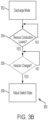
- FIG. 3B illustrates a parallel process 350 that can occur during process 300, including, for example, during act 308 of process 300.
- the process 350 may be executed any number of times during execution of the process 300.
- the BMS 204 is operating the battery pack 200 in a discharge mode of operation (that is, the battery 202 is providing power to the external device and the voltage converter 210 is boosting the voltage).
- the process 350 may then proceed to act 354.
- the BMS 204 determines if the voltage converter 210 should be operated to reduce conduction losses. If the BMS 204 determines the voltage converter 210 should not reduce conduction losses (354 NO), the process 350 may wait (that is, may return to act 354) for a time where the BMS 204 determines that the voltage converter 210 should be operated to reduce conduction losses. If the BMS 204 determines that the voltage converter 210 should be operated to reduce conduction losses, the process 350 continues to optional act 356 or, in examples in which optional act 356 is omitted, directly to act 358.
- the BMS 204 may determine that the voltage converter 210 should be operated to reduce conduction losses on any basis, but may make the determination based on a current through the inductor 216, an insertion loss due to a switch or diode, and so forth.
- the controller determines that the voltage converter 210 should be operated to reduce conduction losses when a diode is capable of supporting an expected current. For example, in the discharge mode, when current is conducted across the second diode 218, the controller may operate the second switch 220. Likewise, when current is conducted across the first diode 212, the controller may operate the first switch 214. Operating the various switches may include opening and/or closing the switches.
- the BMS 204 may determine if the inductor 216 is sufficiently charged.
- the BMS 204 may determine the charge of the inductor 216 in a substantially similar manner as act 306, such as by using sensors or based on a period of time (for example, the BMS 204 may assume the inductor 216 is sufficiently charged in the discharge mode of operation based on a set period of time elapsing). If the BMS 204 determines the inductor 216 is sufficiently charged (356 YES), the process 350 may continue to act 358. If the BMS 204 determines the inductor 216 is not sufficiently charged (356 NO), the process 350 may return to act 356 until the BMS 204 determines the inductor 216 is sufficiently charged.
- the BMS 204 adjusts the state of the switches 214, 220, 226.
- the BMS 204 may switch (that is, open and close) the first switch 214 and/or second switch 220 at a desired frequency.
- the first switch 214 may operate at a frequency greater than a line frequency, and the second switch 220 and the third switch 226 may operate as synchronous rectifiers.
- the third diode 222 may act as a flyback diode for the inductor 216, such that any current discharged from the inductor 216 may pass through the third switch 226 (if the third switch 226 is closed) to the reference node 201, and then return from the reference node 201 through the third diode 222 to the inductor 216.
- FIG. 4A illustrates a process 400 for using the voltage converter 210 to buck the voltage of power received at the first connection 228a according to an example.
- FIG. 4 illustrates at least part of the process used by the BMS 204 to control the battery pack 200 during the charge mode of operation.
- the BMS 204 controls the battery pack 200 to enter a charge mode of operation, and thus controls the voltage converter 210 in a buck mode of operation.
- the BMS 204 may control the voltage converter 210 to be in the buck mode of operation responsive to receiving a signal to operate in the buck mode of operation.
- the signal may be received from the external device, which may include a UPS.
- an external device such as a UPS, may provide recharging power to the battery 202 to replenish the energy stored in the battery 202.
- the process 400 may then continue to act 402.
- the BMS 204 sets the state of the switches 214, 220, 226 to a first state.
- the BMS 204 can set the second switch 220 to a closed position such that a current can pass through the second switch 220 from the first connection 228a to the inductor 216.
- the BMS 204 may set the first switch 214 and the third switch 224 to an open position, such that any current from the inductor 216 to the positive terminal of the battery 202 passes through the first diode 212 and cannot pass to the reference node 201 (for example, cannot pass through the third switch 226 to the reference node 201).
- a conducting loop may exist from the external device to the first connection 228a, through the second switch 220, through the first diode 212 to the positive terminal of the battery 202, and then from the negative terminal of the battery 202 to the second connection 228b and back to the external device.
- the inductor 216 will experience a change in current as the second switch 220 switches from open to closed. As a result, the inductor 216 will store energy as the current passes therethrough. The process 400 may then continue to act 406.
- the BMS 204 determines if the inductor 216 has stored sufficient energy and/or if a desired period of time has passed. If the BMS 204 determines that either condition has been met (406 YES), the process 400 continues to act 408. If the BMS 204 determines that neither condition has been met (406 NO), the process 400 may return to act 406.
- the BMS 204 changes the state of the switches 214, 220, 226 to a second state.
- the second switch 220 may be switched from a closed position to an open position.
- the inductor 216 may discharge some stored energy across the first diode 212 to the battery 202.
- a current loop may be formed where the inductor 216 discharges power through the first diode 212 to the battery 202, with the fourth diode 224 acting as a freewheeling diode for the current to return to the inductor 216.
- the process 400 may then continue to act 410.
- the BMS 204 determines whether the inductor 216 has discharged a sufficient amount of stored energy.
- the BMS 204 may determine that the inductor 216 has discharged a sufficient amount of energy using sensors or by waiting for a period of time to elapse. If the BMS 204 determines that the inductor 216 has discharged a sufficient amount of energy (410 YES), the process 400 continues to act 412. If the BMS 204 determines that the inductor 216 has not discharged a sufficient amount of energy (410 NO), the process 400 may return to act 410.
- the BMS 204 changes the mode of operation of the battery pack 200 and/or voltage converter 210.
- the BMS 204 may change the mode of operation to the discharge mode or any other mode of operation (for example, a mode of operation corresponding to providing trickle charging, such as a trickle-charge mode).
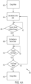
- FIG. 4B illustrates a parallel process 450 than can occur during process 400, including, for example, during act 408 of process 400.
- the process 450 may be executed any number of times during execution of the process 400.
- the BMS 204 is operating the battery pack 200 in a charge mode of operation (that is, the battery 202 is receiving recharging power from the external device and the voltage converter 210 is bucking the voltage).
- the process 450 may then proceed to act 454.
- the BMS 204 determines if the voltage converter 210 should be operated to reduce conduction losses. If the BMS 204 determines the voltage converter 210 should not reduce conduction losses (454 NO), the process 450 may wait (that is, may return to act 454) for a time where the BMS 204 determines that the voltage converter 210 should be operated to reduce conduction losses. If the BMS 204 determines that the voltage converter 210 should be operated to reduce conduction losses, the process 450 continues to optional act 456 in examples in which optional act 456 is omitted, directly to act 458. The BMS 204 may determine that the voltage converter 210 should be operated to reduce conduction losses on any basis, but may make the determination based on a current through the inductor, an insertion loss due to a switch or diode, and so forth.
- the BMS 204 may determine if the inductor 216 is sufficiently charged.
- the BMS 204 may determine the charge of the inductor 216 in a substantially similar manner as act 306, such as by using sensors or based on a period of time (for example, the BMS 204 may assume the inductor 216 is sufficiently charged in the discharge mode of operation based on a set period of time elapsing). If the BMS 204 determines the inductor 216 is sufficiently charged (456 YES), the process 450 may continue to act 458. If the BMS 204 determines the inductor 216 is not sufficiently charged (456 NO), the process 450 may return to act 456 until the BMS 204 determines the inductor 216 is sufficiently charged.
- the BMS 204 adjusts the state of the switches 214, 220, 226.
- the BMS 204 may switch (that is, open and close) the first switch 214 and/or second switch 220 at a desired frequency.
- the third switch 226 may operate at a frequency greater than the line frequency, and the first switch 214 and the second switch 220 may operate as synchronous rectifiers.
- the third diode 222 may act as a flyback diode for the inductor 216, such that any current discharged from the inductor 216 may pass through the third switch 226 (if the third switch 226 is closed) to the reference node 201, and then return from the reference node 201 through the third diode 222 to the inductor 216.
- controllers such as one or more controllers included within the BMS 204 and/or battery pack 200, may execute various operations discussed above. Using data stored in associated memory and/or storage, the one or more controllers also execute one or more instructions stored on one or more non-transitory computer-readable media, which the one or more controllers may include and/or be coupled to, that may result in manipulated data.
- the one or more controllers may include one or more processors or other types of controllers.
- the one or more controllers are or include at least one processor.
- one or more controllers perform at least a portion of the operations discussed above using an application-specific integrated circuit tailored to perform particular operations in addition to, or in lieu of, a general-purpose processor.
- examples in accordance with the present disclosure may perform the operations described herein using many specific combinations of hardware and software and the disclosure is not limited to any particular combination of hardware and software components.
- Examples of the disclosure may include a computer-program product configured to execute methods, processes, and/or operations discussed above.
- the computer-program product may be, or include, one or more controllers and/or processors configured to execute instructions to perform methods, processes, and/or operations discussed above.
- a battery pack comprising:
- Clause 3 The battery pack of clause 2 wherein at least one of the first sensor, the second sensor, or the third sensor are configured to provide a respective detected value to the at least one controller.
- the battery pack of clause 1 further comprising a trickle charger coupled to the bus connection and to the battery.
- Clause 6 The battery pack of clause 6 wherein the first diode operates as a freewheeling diode in the buck mode of operation and the second diode operates as a freewheeling diode in the boost mode of operation.
- Clause 7 The battery pack of clause 1 wherein the voltage converter further comprises a first switching device coupled in parallel with the first diode, wherein the first switching device is coupled between the first inductor connection and the reference node.
- a method of operating a battery pack comprising:
- Clause 13 The method of clause 11 wherein the frequency is adjustable and determined by at least one controller configured to operate the at least one switching device.
- Clause 14 The method of clause 11 further comprising, responsive to determining that the power is to be received from the external device, synchronously rectifying the power to reduce conduction losses.
- Clause 16 The method of clause 11 further comprising, responsive to determining that the power is to be provided to the external device, monitoring for a fault condition.
- Clause 17 The method of clause 16 further comprising reducing, responsive to detecting the fault condition, the voltage of the power.
- a non-transitory, computer-readable medium storing thereon instructions for operating a battery pack having a battery and a voltage converter, the instructions instructing at least one processor to:
Landscapes
- Engineering & Computer Science (AREA)
- Power Engineering (AREA)
- Chemical & Material Sciences (AREA)
- Chemical Kinetics & Catalysis (AREA)
- Electrochemistry (AREA)
- General Chemical & Material Sciences (AREA)
- Business, Economics & Management (AREA)
- Emergency Management (AREA)
- Manufacturing & Machinery (AREA)
- Charge And Discharge Circuits For Batteries Or The Like (AREA)
- Dc-Dc Converters (AREA)
Abstract
Description
- At least one example in accordance with the present disclosure relates generally to controlling the voltage of power provided to or from a battery.
- Power devices, such as uninterruptible power supplies (UPSs), may be used to provide regulated, uninterrupted power for sensitive and/or critical loads, such as computer systems and other data-processing systems. Existing UPSs include online UPSs, offline UPSs, line-interactive UPSs, as well as others. UPSs may provide output power to a load. The output power may be derived from a primary source of power, such as a utility-mains source, and/or derived from a back-up source of power, such as an energy-storage device.
- The disclosure is defined in the appended independent claims. Dependent claims constitute embodiments of the disclosure. In the present description and drawings, any examples and technical descriptions of apparatuses products and/or methods which are not covered by the claims should be taken as background art or examples useful for understanding the disclosure.
- Various aspects of at least one embodiment are discussed below with reference to the accompanying figures, which are not intended to be drawn to scale. The figures are included to provide an illustration and a further understanding of the various aspects and embodiments, and are incorporated in and constitute a part of this specification, but are not intended as a definition of the limits of any particular embodiment. The drawings, together with the remainder of the specification, serve to explain principles and operations of the described and claimed aspects and embodiments. In the figures, each identical or nearly identical component that is illustrated in various figures is represented by a like numeral. For purposes of clarity, not every component may be labeled in every figure. In the figures:
-
FIG. 1 illustrates a power system according to an example; -
FIG. 2 illustrates a battery pack according to an example; -
FIG. 3A illustrates a process for boosting a voltage using a voltage converter according to an example; -
FIG. 3B illustrates a parallel process for synchronous rectification according to an example; -
FIG. 4A illustrates a process for bucking a voltage according to an example; and -
FIG. 4B illustrates a parallel process for synchronous rectification according to an example. - Examples of the methods and systems discussed herein are not limited in application to the details of construction and the arrangement of components set forth in the following description or illustrated in the accompanying drawings. The methods and systems are capable of implementation in other embodiments and of being practiced or of being carried out in various ways. Examples of specific implementations are provided herein for illustrative purposes only and are not intended to be limiting. In particular, acts, components, elements and features discussed in connection with any one or more examples are not intended to be excluded from a similar role in any other examples.
- Also, the phraseology and terminology used herein is for the purpose of description and should not be regarded as limiting. Any references to examples, embodiments, components, elements or acts of the systems and methods herein referred to in the singular may also embrace embodiments including a plurality, and any references in plural to any embodiment, component, element or act herein may also embrace embodiments including only a singularity. References in the singular or plural form are not intended to limit the presently disclosed systems or methods, their components, acts, or elements. The use herein of "including," "comprising," "having," "containing," "involving," and variations thereof is meant to encompass the items listed thereafter and equivalents thereof as well as additional items.
- References to "or" may be construed as inclusive so that any terms described using "or" may indicate any of a single, more than one, and all of the described terms.
- Batteries have chemistries and characteristics that can pose challenges in certain applications. For examples, when connected in parallel to provide or receive power, batteries of different internal chemistries may have different voltages, discharge and charge rates, stored charge, and so forth. As a result, it may not be effective to charge or discharge batteries in parallel in an efficient manner simply by connecting the batteries in parallel to a charging bus. Likewise, batteries may have different charging needs. For example, a given battery may be able to charge rapidly when its internal voltage is within a certain range, but may need to charge less rapidly when the voltage is above or below a threshold voltage level (for example, when the battery is nearly fully charged and has a corresponding fully charged voltage level).
- Aspects and elements of the present disclosure relate to a battery pack configured to adjust the voltage provided by the battery or received by the battery. In some examples, the battery pack uses a circuit that can increase (boost) or decrease (buck) a voltage, called a "buck/boost circuit" or "voltage converter." By boosting and bucking the voltage, the voltage converter allows the battery to be placed in parallel with other batteries (for example, to charge and discharge) without regard to the internal chemistry or other internal characteristics of the batteries.
-
FIG. 1 illustrates apower system 100 according to an example. Thepower system 100 includes abattery pack 102, an uninterruptible power supply (UPS) 104, acharging bus 106a, areturn bus 106b, acommunications connection 108, and, in some examples, anoptional impedance 110. - The
battery pack 102 is configured to provide backup power to the UPS 104 at least when the UPS 104 does not have access to acceptable power from a different power source (for example, a utility mains supply). Thebattery pack 102 may be further configured to receive charging power from the UPS 104 when the UPS 104 has acceptable power available from a different power source. Thebattery pack 102 may contain one or more batteries, and the batteries may be connected in series and/or parallel within thebattery pack 102. Thebattery pack 102 will be discussed in greater detail with respect toFIG. 2 . - The UPS 104 may be implemented according to any of various UPS topologies. The UPS 104 may be connected to, and receive input power from, a main power source (such as a utility power grid or a main power generator) and the
battery pack 102. The UPS 104 may further be connected to, and provide uninterrupted power to, one or more loads. When main power is available (for example, utility grid power or power from a generator), the UPS directs the main power to the one or more loads and may direct the main power to the battery pack 102 (or battery packs, if more than one battery pack is present) to recharge one or more batteries of thebattery pack 102. In many examples, thecharging bus 106a carries power from thebattery pack 102 to the UPS 104 or from the UPS 104 to thebattery pack 102, while thereturn bus 106b is a reference node. Accordingly, while thecharging bus 106a is referred to with the word "charging," discharged power (that is, power discharged from thebattery pack 102 to the UPS 104) may also be provided via thecharging bus 106a. - The UPS 104 and
battery pack 102 may be configured to communicate with one another. In some examples, the UPS 104 andbattery pack 102 communicate via thecommunications connection 108. Thecommunications connection 108 may include a physical communication medium of thepower system 100, for example, an Ethernet cable, a phone cord, and/or a wire or set of wires configured to carry information from one device to another. In other examples, thecommunications connection 108 may include one or more components to facilitate wireless communication, for example, a wireless transceiver or other device. - The
optional impedance 110 may include a capacitor, inductor, or other device capable of storing charge and/or energy. In some examples, theoptional impedance 110 includes a capacitor. Theoptional impedance 110 may be coupled between thebattery pack 102 and theUPS 104, or theoptional impedance 110 may be part of thebattery pack 102 orUPS 104. For example, theoptional impedance 110 may include a capacitor located on the portion of the chargingbus 106a located within theUPS 104. -
FIG. 2 illustrates abattery pack 200 according to an example. Thebattery pack 102 ofFIG. 1 may be implemented according to the topology and characteristics of thebattery pack 200 ofFIG. 2 . That is, thebattery pack 200 ofFIG. 2 represents at least one embodiment of thebattery pack 102 ofFIG. 1 , and thebattery pack 200 ofFIG. 2 may be substituted for thebattery pack 102 ofFIG. 1 with respect to the discussion ofFIG. 1 . - The
battery pack 200 includes areference node 201, at least one battery 202 ("battery 202"), a battery management system (BMS) 204, atrickle charger 206, one ormore sensors 208, avoltage converter 210, afirst connection 228a (or a "chargingbus connection 228a"), asecond connection 228b (or a "return bus connection 228b"), and acommunications connection 230. Thevoltage converter 210 includes afirst diode 212, a first switch 214, an inductive element 216 ("inductor 216"), asecond diode 218, asecond switch 220, athird diode 222, afourth diode 224, and athird switch 226. In some examples, thefirst diode 212 and the first switch 214, thesecond diode 218 and thesecond switch 220, and thefourth diode 224 and thethird switch 226 may each be implemented as a single physical switching device, but are represented by an ideal switch and an intrinsic body diode. - The
battery 202 is coupled to at least one of the one ormore sensors 208, thetrickle charger 206, and thevoltage converter 210. In some examples, thebattery 202 is coupled to thevoltage converter 210 via thefirst diode 212 and the first switch 214. Thebattery 202 may also be coupled to thesecond connection 228b. In examples where thebattery 202 includes more than one battery, the constituent batteries of thebattery 202 may be coupled together with one another in parallel and/or series. - The
trickle charger 206 is coupled to thebattery 202, thefirst connection 228a, and thevoltage converter 210. In some examples, thetrickle charger 206 is coupled to thevoltage converter 210 via both the combination of thefirst diode 212 and the first switch 214 and the combination of thesecond diode 218 and thesecond switch 220. - The one or
more sensors 208 may be located in various positions within thebattery pack 200. For example, at least one sensor may be implemented to sense a voltage across thefirst connection 228a and thesecond connection 228b, to sense a voltage across thebattery 202, to sense a current provided to and/or received from thebattery 202 via the first andsecond connections - The
BMS 204 may be coupled to one or more of the one ormore sensors 208, the first, second, and/orthird switches trickle charger 206, and/or thecommunication connection 230. - The
voltage converter 210 may have a first converter connection and a second converter connection, the first connection being coupled to thebattery 202 and the second connection being coupled to thefirst connection 228a. Within thevoltage converter 210, thefirst diode 212 and first switch 214 may be coupled in parallel with one another and further be coupled to theinductor 216 and thethird diode 222. Theinductor 216 may be coupled to each of the first, second, third, and/orfourth diodes inductor 216 may be coupled to the first, second, and/orthird switches inductor 216 may have a first inductor connection coupled to thefirst diode 212 and a second inductor connection coupled to thesecond diode 218. In some examples, thesecond diode 218,second switch 220,fourth diode 224 andthird switch 226 are coupled to the second inductor connection of theinductor 216. In some examples, thefirst diode 212, first switch 214, andthird diode 222 are coupled to the first inductor connection of theinductor 216. Thesecond diode 218 andsecond switch 220 may be coupled in parallel with one another and further be coupled to theinductor 216, thefourth diode 224, and thethird switch 226. Thefourth diode 224 andthird switch 226 may be coupled in parallel with one another and further coupled to a reference node (such as areference node 201 to which thesecond connection 228b is coupled) as well as to theinductor 216, thesecond diode 218, and thesecond switch 220. Thethird diode 222 may be coupled to thereference node 201 as well as thefirst diode 212, first switch 214, and/orinductor 216. In examples where thereference node 201 corresponds to thesecond connection 228b and/or the bus of thebattery pack 200 coupled to thesecond connection 228b, anything coupled to thesecond connection 228b may also be coupled to thebattery 202. - In some examples, a cathode of the
first diode 212 is coupled to thebattery 202 and an anode of thefirst diode 212 is coupled to theinductor 216. In some examples, a cathode of thesecond diode 218 is coupled to thefirst connection 228a and an anode of thesecond diode 218 is coupled to theinductor 216. In some examples, a cathode of thethird diode 222 is coupled to theinductor 216. In some examples, a cathode of thefourth diode 224 is coupled to theinductor 216. In some examples, the cathode of thethird diode 222 is coupled to the anode of thefirst diode 212. In some examples, the cathode of thefourth diode 224 is coupled to the anode of thesecond diode 218. - The
battery 202 may include any of various types of battery or energy-storage device. Thebattery 202 may have an internal chemistry suitable for storing power and/or energy. In some examples, thebattery 202 may be a rechargeable battery. - The
BMS 204 is configured to control at least theswitches battery pack 200, as well as thetrickle charger 206. In some examples, theBMS 204 may include a controller, processor, circuit, and/or other device or collection of devices capable of controlling thebattery pack 200. TheBMS 204 may control theswitches BMS 204 may control each switch individually, such that when one switch is open the others may be closed or open independent of the state of any other switch. TheBMS 204 may also control thetrickle charger 206 to be in an on state (that is, providing trickle charging) or an off state (that is, not providing trickle charging). TheBMS 204 may also be coupled to the one ormore sensors 208. In some examples, theBMS 204 is configured to receive, from the one ormore sensors 208, sensed information indicative of the voltage across theconnections battery 202, and/or the current through (either to or from) thebattery 202. TheBMS 204 may be configured to communicate with external devices. In some examples, theBMS 204 may be configured to communicate with a UPS (for example, the UPS 104) or other external power system. TheBMS 204 may transmit and/or receive any information, such as voltage, current, power, energy, and/or state-of-charge (SOC) information, and/or other types of power-system-related information. - The
trickle charger 206 is configured to provide trickle charging to thebattery 202 under certain conditions. Trickle charging may include charging thebattery 202 at a rate equal to the discharge rate of thebattery 202 when thebattery 202 is not actively discharging power, thus ensuring thebattery 202 remains at a substantially constant SOC. Trickle charging may also include charging thebattery 202 at a slower rate when thebattery 202 is near a desired voltage level (such as a maximum voltage level or an optimum voltage level) such that thebattery 202 is not overcharged. Trickle charging may also be used when thebattery 202 is in a state of deep discharge (that is, the SOC is very low), to allow thebattery 202 to recover from the state of deep discharge without suffering damage. - The
first connection 228a is a connection node through which a bus, such as the chargingbus 106a, may connect to thebattery pack 102. Thesecond connection 228b is a connection node through which a bus, such as thereturn bus 106b, may connect to thebattery pack 102. Thecommunications connection 230 may include a wired connection port (such as an Ethernet port) or a wireless connection (such as a wireless transceiver) with which theBMS 204 may communicate with external devices, such as a UPS. - The
voltage converter 210 is a circuit configured to increase (boost) and/or reduce (buck) voltages of power passing through thevoltage converter 210. Thevoltage converter 210 may operate in a boost mode of operation, where thevoltage converter 210 may increase the voltage of power, or thevoltage converter 210 may operate in a buck mode of operation, where thevoltage converter 210 may reduce the voltage of power. Thefirst diode 212 may operate as a freewheeling diode in the buck mode of operation and thesecond diode 218 may operate as a freewheeling diode in the boost mode of operation. TheBMS 204 may control the mode of operation of thevoltage converter 210 by controlling theswitches voltage converter 210 as will be described in greater detail below. - The
switches BMS 204 at desired frequencies depending on the mode of operation of thevoltage converter 210 such that theswitches voltage converter 210 to create a duty cycle or operate as a synchronous rectifier. The operation of theswitches FIGS. 3A ,3B ,4A , and4B . - The
BMS 204 operates theswitches inductor 216 accumulates energy over time, and then discharges over time. In some examples, a capacitor or other optional impedance (such asoptional impedance 110 ofFIG. 1 ) may be coupled to thefirst connection 228a and may also store energy for discharge over time. Theinductor 216 and possibly the capacitor are used to store energy such that the voltage of power provided by the inductor 216 (or capacitor) during discharge is higher or lower than the voltage of the chargingbus 106a (for example, the voltage provided by a UPS). - In some examples, the boost mode of operation of the
voltage converter 210 corresponds to a discharge mode of operation of thebattery 202, where thebattery 202 and thevoltage converter 210 are providing boosted power to an external device such as a UPS. In some examples, the buck mode of operation of thevoltage converter 210 corresponds to a charge mode of operation of thebattery 202, where thebattery 202 is receiving bucked power from an external device such as a UPS. -
FIG. 3A illustrates a process for increasing the voltage using thevoltage converter 210 during a boost mode of operation according to an example. In some examples,FIG. 3 illustrates at least part of the process used by theBMS 204 to control thebattery pack 200 during the discharge mode of operation. - At
act 302, theBMS 204 controls thebattery pack 200 to enter a discharge mode of operation and thus controls thevoltage converter 210 in a boost mode of operation. TheBMS 204 may control thevoltage converter 210 to be in the boost mode of operation responsive to receiving a signal to operate in the boost mode of operation. For example, the signal may be received from the external device, which may include a UPS. In the discharge mode of operation, theBMS 204 operates thevoltage converter 210 to boost the voltage of power discharged by thebattery 202. Thevoltage converter 210 provides the boosted power to an external device. In the discharge mode of operation, thetrickle charger 206 may be turned off. Theprocess 300 may then continue to act 304. - At
act 304, theBMS 204 sets the state of theswitches voltage converter 210 to be in a first state. The first state corresponds to a time during which theinductor 216 is charged up. In the first state, the first switch 214 may be closed (that is, conducting), thesecond switch 220 may be open (that is, not conducting), and thethird switch 226 may be closed. In this first state, a current loop is formed from the positive terminal of thebattery 202 through the first switch 214, through theinductor 216, then through thethird switch 226 and to the negative terminal of thebattery 202. Due to the lack of large impedances in this current loop, the loop will behave roughly like a short circuit. When theswitches inductor 216 will store energy due to the large current passing therethrough. Theprocess 300 may then continue to act 306. - At
act 306, theBMS 204 determines if theinductor 216 has stored at least a threshold amount of energy. The threshold amount of energy may correspond to, or be determined based on, a desired degree to which the power is to be boosted. In some examples, theBMS 204 may determine whether a period of time has elapsed since beginning to charge theinductor 216. The threshold amount of time may correspond to, or be determined based on, a desired degree to which the power is to be boosted. The threshold period of time and/or amount of energy may be determined by the user or the design features of the circuit. If theinductor 216 has stored at least the threshold amount of energy or the period of time has elapsed (306 YES), the process may continue to act 308. If the controller determines that the threshold amount of energy or the period of time have not yet been satisfied (306 NO), the process may wait (that is, stay at or return to act 306). - At
act 308, theBMS 204 controls theswitches inductor 216 is discharged. In the second state, thethird switch 226 is opened, while the first switch 214 remains closed and thesecond switch 220 remains open. Power then flows from the positive terminal of thebattery 202 through the first switch 214, theinductor 216, and through thesecond diode 218 to thefirst connection 228a (for example, to theoptional impedance 110, which may include a capacitor), and then back to the negative terminal of thebattery 202 via thesecond connection 228b. The voltage of the power discharged by thebattery 202 is added to the voltage produced across theinductor 216 while theinductor 216 discharges, thereby boosting the voltage of the power output by thebattery 202. In examples in which theoptional impedance 110 is implemented with a capacitor, the capacitor is charged until the voltage across the capacitor is at a higher level than the voltage of a DC bus, such as the charging bus. Thesecond diode 218 prevents the charge on the capacitor from discharging back to the positive terminal of thebattery 202. The process may then continue to act 310. - At
act 310, theBMS 204 determines if theinductor 216 is sufficiently discharged of the energy stored duringact 304. Being sufficiently discharged may include being discharged of at least a threshold amount of energy. Alternatively, theBMS 204 may wait for a period of time (for example, a predetermined amount of time) corresponding to an amount of time necessary for theinductor 216 to discharge. If theBMS 204 determines that the inductor is discharged or the period of time has elapsed (310 YES), theprocess 300 may continue to act 312. If theBMS 204 determines the inductor is not discharged or the period of time has not elapsed (310 NO), theprocess 300 may return to act 310. - At
act 312, theBMS 204 determines if thebattery pack 200 should remain in discharge mode. TheBMS 204 may, for example, determine that no signal has been received from the external device (such as the UPS 104) instructing thebattery pack 200 to remain (or not remain) in discharge mode, or may receive a signal indicating that thebattery pack 200 should exit the discharge mode. If theBMS 204 determines thebattery pack 200 should not remain in discharge mode (312 YES), theprocess 300 may continue to act 314. If theBMS 204 determines thebattery pack 200 should remain in discharge mode (312 NO), theprocess 300 may return to act 304. - At
act 314, theBMS 204 switches thebattery pack 200 to a different state and may activate or deactivate thetrickle charger 206 or change the state of theswitches voltage converter 210 depending on which mode of operation thebattery pack 200 is switched to. The controller of theBMS 204 may further monitor for a fault condition. The controller may further deactivate the boost mode of operation responsive to detecting a fault condition, i.e., reduce the voltage of the power. -
FIG. 3B illustrates aparallel process 350 that can occur duringprocess 300, including, for example, duringact 308 ofprocess 300. Theprocess 350 may be executed any number of times during execution of theprocess 300. - At
act 352, theBMS 204 is operating thebattery pack 200 in a discharge mode of operation (that is, thebattery 202 is providing power to the external device and thevoltage converter 210 is boosting the voltage). Theprocess 350 may then proceed to act 354. - At
act 354, theBMS 204 determines if thevoltage converter 210 should be operated to reduce conduction losses. If theBMS 204 determines thevoltage converter 210 should not reduce conduction losses (354 NO), theprocess 350 may wait (that is, may return to act 354) for a time where theBMS 204 determines that thevoltage converter 210 should be operated to reduce conduction losses. If theBMS 204 determines that thevoltage converter 210 should be operated to reduce conduction losses, theprocess 350 continues tooptional act 356 or, in examples in whichoptional act 356 is omitted, directly to act 358. TheBMS 204 may determine that thevoltage converter 210 should be operated to reduce conduction losses on any basis, but may make the determination based on a current through theinductor 216, an insertion loss due to a switch or diode, and so forth. In some examples, the controller determines that thevoltage converter 210 should be operated to reduce conduction losses when a diode is capable of supporting an expected current. For example, in the discharge mode, when current is conducted across thesecond diode 218, the controller may operate thesecond switch 220. Likewise, when current is conducted across thefirst diode 212, the controller may operate the first switch 214. Operating the various switches may include opening and/or closing the switches. - At
optional act 356, theBMS 204 may determine if theinductor 216 is sufficiently charged. TheBMS 204 may determine the charge of theinductor 216 in a substantially similar manner asact 306, such as by using sensors or based on a period of time (for example, theBMS 204 may assume theinductor 216 is sufficiently charged in the discharge mode of operation based on a set period of time elapsing). If theBMS 204 determines theinductor 216 is sufficiently charged (356 YES), theprocess 350 may continue to act 358. If theBMS 204 determines theinductor 216 is not sufficiently charged (356 NO), theprocess 350 may return to act 356 until theBMS 204 determines theinductor 216 is sufficiently charged. - At
act 358, theBMS 204 adjusts the state of theswitches BMS 204 may switch (that is, open and close) the first switch 214 and/orsecond switch 220 at a desired frequency. The first switch 214 may operate at a frequency greater than a line frequency, and thesecond switch 220 and thethird switch 226 may operate as synchronous rectifiers. When the first switch 214 is open, thethird diode 222 may act as a flyback diode for theinductor 216, such that any current discharged from theinductor 216 may pass through the third switch 226 (if thethird switch 226 is closed) to thereference node 201, and then return from thereference node 201 through thethird diode 222 to theinductor 216. -
FIG. 4A illustrates aprocess 400 for using thevoltage converter 210 to buck the voltage of power received at thefirst connection 228a according to an example. In some examples,FIG. 4 illustrates at least part of the process used by theBMS 204 to control thebattery pack 200 during the charge mode of operation. - At
act 402, theBMS 204 controls thebattery pack 200 to enter a charge mode of operation, and thus controls thevoltage converter 210 in a buck mode of operation. TheBMS 204 may control thevoltage converter 210 to be in the buck mode of operation responsive to receiving a signal to operate in the buck mode of operation. For example, the signal may be received from the external device, which may include a UPS. In the charge mode of operation, an external device, such as a UPS, may provide recharging power to thebattery 202 to replenish the energy stored in thebattery 202. Theprocess 400 may then continue to act 402. - At
act 404, theBMS 204 sets the state of theswitches BMS 204 can set thesecond switch 220 to a closed position such that a current can pass through thesecond switch 220 from thefirst connection 228a to theinductor 216. TheBMS 204 may set the first switch 214 and thethird switch 224 to an open position, such that any current from theinductor 216 to the positive terminal of thebattery 202 passes through thefirst diode 212 and cannot pass to the reference node 201 (for example, cannot pass through thethird switch 226 to the reference node 201). Thus, duringact 404, a conducting loop may exist from the external device to thefirst connection 228a, through thesecond switch 220, through thefirst diode 212 to the positive terminal of thebattery 202, and then from the negative terminal of thebattery 202 to thesecond connection 228b and back to the external device. Duringact 404, theinductor 216 will experience a change in current as thesecond switch 220 switches from open to closed. As a result, theinductor 216 will store energy as the current passes therethrough. Theprocess 400 may then continue to act 406. - At
act 406, theBMS 204 determines if theinductor 216 has stored sufficient energy and/or if a desired period of time has passed. If theBMS 204 determines that either condition has been met (406 YES), theprocess 400 continues to act 408. If theBMS 204 determines that neither condition has been met (406 NO), theprocess 400 may return to act 406. - At
act 408, theBMS 204 changes the state of theswitches second switch 220 may be switched from a closed position to an open position. As a result of such a change, theinductor 216 may discharge some stored energy across thefirst diode 212 to thebattery 202. A current loop may be formed where theinductor 216 discharges power through thefirst diode 212 to thebattery 202, with thefourth diode 224 acting as a freewheeling diode for the current to return to theinductor 216. Theprocess 400 may then continue to act 410. - At
act 410, theBMS 204 determines whether theinductor 216 has discharged a sufficient amount of stored energy. TheBMS 204 may determine that theinductor 216 has discharged a sufficient amount of energy using sensors or by waiting for a period of time to elapse. If theBMS 204 determines that theinductor 216 has discharged a sufficient amount of energy (410 YES), theprocess 400 continues to act 412. If theBMS 204 determines that theinductor 216 has not discharged a sufficient amount of energy (410 NO), theprocess 400 may return to act 410. - At
act 412, theBMS 204 determines whether thevoltage converter 210 and/orbattery pack 200 should continue to operate in the charge mode. TheBMS 204 may, for example, determine whether any instructions or signals indicating that thebattery pack 200 should or should not change mode have been received. If theBMS 204 determines thebattery pack 200 and/orvoltage converter 210 should not continue to operate in the charge mode (412 YES), theprocess 400 continues to act 416. If theBMS 204 determines that thebattery pack 200 should remain in the charge mode (412 NO), theprocess 400 may return to act 404. - At
act 416, theBMS 204 changes the mode of operation of thebattery pack 200 and/orvoltage converter 210. TheBMS 204 may change the mode of operation to the discharge mode or any other mode of operation (for example, a mode of operation corresponding to providing trickle charging, such as a trickle-charge mode). -
FIG. 4B illustrates aparallel process 450 than can occur duringprocess 400, including, for example, duringact 408 ofprocess 400. Theprocess 450 may be executed any number of times during execution of theprocess 400. - At
act 452, theBMS 204 is operating thebattery pack 200 in a charge mode of operation (that is, thebattery 202 is receiving recharging power from the external device and thevoltage converter 210 is bucking the voltage). Theprocess 450 may then proceed to act 454. - At
act 454, theBMS 204 determines if thevoltage converter 210 should be operated to reduce conduction losses. If theBMS 204 determines thevoltage converter 210 should not reduce conduction losses (454 NO), theprocess 450 may wait (that is, may return to act 454) for a time where theBMS 204 determines that thevoltage converter 210 should be operated to reduce conduction losses. If theBMS 204 determines that thevoltage converter 210 should be operated to reduce conduction losses, theprocess 450 continues tooptional act 456 in examples in whichoptional act 456 is omitted, directly to act 458. TheBMS 204 may determine that thevoltage converter 210 should be operated to reduce conduction losses on any basis, but may make the determination based on a current through the inductor, an insertion loss due to a switch or diode, and so forth. - At
optional act 456, theBMS 204 may determine if theinductor 216 is sufficiently charged. TheBMS 204 may determine the charge of theinductor 216 in a substantially similar manner asact 306, such as by using sensors or based on a period of time (for example, theBMS 204 may assume theinductor 216 is sufficiently charged in the discharge mode of operation based on a set period of time elapsing). If theBMS 204 determines theinductor 216 is sufficiently charged (456 YES), theprocess 450 may continue to act 458. If theBMS 204 determines theinductor 216 is not sufficiently charged (456 NO), theprocess 450 may return to act 456 until theBMS 204 determines theinductor 216 is sufficiently charged. - At
act 458, theBMS 204 adjusts the state of theswitches BMS 204 may switch (that is, open and close) the first switch 214 and/orsecond switch 220 at a desired frequency. Thethird switch 226 may operate at a frequency greater than the line frequency, and the first switch 214 and thesecond switch 220 may operate as synchronous rectifiers. When the first switch 214 is open, thethird diode 222 may act as a flyback diode for theinductor 216, such that any current discharged from theinductor 216 may pass through the third switch 226 (if thethird switch 226 is closed) to thereference node 201, and then return from thereference node 201 through thethird diode 222 to theinductor 216. - With respect to the foregoing processes 300, 350, 400, 450, the acts may be executed in any order, and at a high frequency. In some examples, high frequencies may correspond to the switches changing state (from opened to closed and/or closed to open) at a frequency of approximately 50 kHz. In general, the frequency of operation may be selected such that the
inductor 216 is kept in a continuous conduction mode. - Various controllers, such as one or more controllers included within the
BMS 204 and/orbattery pack 200, may execute various operations discussed above. Using data stored in associated memory and/or storage, the one or more controllers also execute one or more instructions stored on one or more non-transitory computer-readable media, which the one or more controllers may include and/or be coupled to, that may result in manipulated data. In some examples, the one or more controllers may include one or more processors or other types of controllers. In one example, the one or more controllers are or include at least one processor. In another example, one or more controllers perform at least a portion of the operations discussed above using an application-specific integrated circuit tailored to perform particular operations in addition to, or in lieu of, a general-purpose processor. As illustrated by these examples, examples in accordance with the present disclosure may perform the operations described herein using many specific combinations of hardware and software and the disclosure is not limited to any particular combination of hardware and software components. Examples of the disclosure may include a computer-program product configured to execute methods, processes, and/or operations discussed above. The computer-program product may be, or include, one or more controllers and/or processors configured to execute instructions to perform methods, processes, and/or operations discussed above. - Further examples are provided in the following clauses.
- Clause 1. A battery pack comprising:
- a battery;
- a bus connection configured to allow power to pass between the battery and an external device;
- a voltage converter configured to increase a voltage of the power in a boost mode of operation and to decrease the voltage of the power in a buck mode of operation, the voltage converter including:
- a first connection coupled to the bus connection,
- a second connection coupled to the battery,
- an inductor having a first inductor connection coupled to the first connection and a second inductor connection coupled to the second connection,
- a first diode coupled to the first inductor connection and to a reference node, and
- a second diode coupled to the second inductor connection and to the reference node; and
- at least one controller configured to
operate the voltage converter in the boost mode of operation responsive to receiving a signal to operate in the boost mode of operation, and - operate the voltage converter in a buck mode of operation responsive to receiving a signal to operate in the buck mode of operation.
- Clause 2. The battery pack of clause 1 further comprising:
- a first sensor configured to detect a battery current;
- a second sensor configured to detect a voltage at the input; and
- a third sensor configured to detect a voltage of the battery.
- Clause 3. The battery pack of clause 2 wherein at least one of the first sensor, the second sensor, or the third sensor are configured to provide a respective detected value to the at least one controller.
- Clause 4. The battery pack of clause 1 further comprising at least one additional battery coupled in series with the battery.
- Clause 5. The battery pack of clause 1 further comprising a trickle charger coupled to the bus connection and to the battery.
- Clause 6. The battery pack of clause 6 wherein the first diode operates as a freewheeling diode in the buck mode of operation and the second diode operates as a freewheeling diode in the boost mode of operation.
- Clause 7. The battery pack of clause 1 wherein the voltage converter further comprises a first switching device coupled in parallel with the first diode, wherein the first switching device is coupled between the first inductor connection and the reference node.
- Clause 8. The battery pack of clause 7 wherein the voltage converter further comprises:
- a second switching device coupled in parallel with a third diode, wherein the second switching device is coupled to the battery; and
- a third switching device coupled in parallel with a fourth diode, wherein the third switching device is coupled to the bus connection.
- Clause 9. The battery pack of clause 8 wherein the controller is further configured to:
- operate, in the boost mode of operation,
- the first switching device at a frequency greater than a line frequency, and
- the second switching device and the third switching device as synchronous rectifiers; and
- operate, in the buck mode of operation,
the third switching device at a frequency greater than the line frequency, and - the first switching device and the second switching device as synchronous rectifiers.
- Clause 10. The battery pack of clause 1 wherein the controller is further configured to, in the boost mode of operation, deactivate the boost mode of operation responsive to detecting a fault condition.
- Clause 11. A method of operating a battery pack, the method comprising:
- determining whether power is to be provided to an external device or received from an external device;
- responsive to determining that the power is to be provided to the external device or received from an external device, operating at least one switching device of the battery pack as a synchronous rectifier at a frequency higher than a line frequency of the external device;
- responsive to determining that the power is to be provided to the external device, boosting a voltage of the power and providing the power to the external device; and
- responsive to determining that the power is to be received from an external device, reducing the voltage of the power.
- Clause 12. The method of clause 11 further comprising:
- responsive to determining that the power is to be received from the external device, determining that the voltage of the power is below a threshold voltage;
- responsive to determining that the voltage is below the threshold voltage, routing the power through a trickle charger; and
- responsive to determining that the voltage is below the threshold voltage, maintaining a voltage level of the voltage of the power.
- Clause 13. The method of clause 11 wherein the frequency is adjustable and determined by at least one controller configured to operate the at least one switching device.
- Clause 14. The method of clause 11 further comprising, responsive to determining that the power is to be received from the external device, synchronously rectifying the power to reduce conduction losses.
- Clause 15. The method of clause 11 further comprising, responsive to determining that the power is to be provided to the external device, synchronously rectifying the power to reduce conduction losses.
- Clause 16. The method of clause 11 further comprising, responsive to determining that the power is to be provided to the external device, monitoring for a fault condition.
- Clause 17. The method of clause 16 further comprising reducing, responsive to detecting the fault condition, the voltage of the power.
- Clause 18. A non-transitory, computer-readable medium storing thereon instructions for operating a battery pack having a battery and a voltage converter, the instructions instructing at least one processor to:
- control the voltage converter to increase a voltage of power responsive to determining that the power is to be provided to an external device;
- control the voltage converter to decrease a voltage of the power responsive to determining that the power is to be received from the external device; and
- responsive to controlling the voltage converter to increase or decrease the voltage, control at least one switching device of the battery pack to operate as a synchronous rectifier at a frequency higher than a line frequency of the external device.
- Clause 19. The non-transitory, computer-readable medium of clause 18 wherein the instructions further instruct the at least one processor to operate at least one other switching device as a synchronous rectifier to reduce conduction losses. Clause 20. The non-transitory, computer readable medium of clause 18 wherein the instructions further instruct the at least one processor to:
- determine whether the voltage of the power is within a threshold voltage of the voltage of the battery;
- deactivate the voltage converter responsive to determining that the voltage of the power is within the threshold voltage; and
- activate a trickle charger responsive to determining that the voltage of the power is within the threshold voltage.
Claims (15)
- A battery pack (102; 200) comprising:a battery (202);a bus connection (106a) configured to allow power to pass between the battery and an external device;a voltage converter (210) configured to increase a voltage of the power in a boost mode of operation and to decrease the voltage of the power in a buck mode of operation, the voltage converter including:a first connection (228a) coupled to the bus connection,a second connection (228b) coupled to the battery,an inductor having a first inductor connection coupled to the first connection and a second inductor connection coupled to the second connection,a first diode (212) coupled to the first inductor connection and to a reference node, anda second diode (218) coupled to the second inductor connection and to the reference node; andat least one controller configured tooperate the voltage converter in the boost mode of operation responsive to receiving a signal to operate in the boost mode of operation, andoperate the voltage converter in a buck mode of operation responsive to receiving a signal to operate in the buck mode of operation.
- The battery pack of claim 1 further comprising:a first sensor (208) configured to detect a battery current;a second sensor (208) configured to detect a voltage at the input; anda third sensor (208) configured to detect a voltage of the battery.
- The battery pack of any of the above claims further comprising at least one additional battery coupled in series with the battery.
- The battery pack of any of the above claims further comprising a trickle charger (206) coupled to the bus connection (228a) and to the battery (202).
- The battery pack of any of the above claims wherein the first diode operates as a freewheeling diode in the buck mode of operation and the second diode operates as a freewheeling diode in the boost mode of operation.
- The battery pack of any of the above claims wherein the voltage converter further comprises a first switching device (214) coupled in parallel with the first diode (212), wherein the first switching device (214) is coupled between the first inductor connection and the reference node (201).
- The battery pack of claim 6 wherein the voltage converter further comprises:a second switching device (220) coupled in parallel with a third diode (222), wherein the second switching device (220) is coupled to the battery (202); anda third switching device (226) coupled in parallel with a fourth diode (224), wherein the third switching device (226) is coupled to the bus connection.
- The battery pack of claim 7 wherein the controller is further configured to:operate, in the boost mode of operation,the first switching device (214) at a frequency greater than a line frequency, andthe second switching device (220) and the third switching device (226) as synchronous rectifiers; andoperate, in the buck mode of operation,the third switching device (226) at a frequency greater than the line frequency, andthe first switching device (214) and the second switching device (220) as synchronous rectifiers.
- The battery pack of any of the above claims wherein the controller is further configured to, in the boost mode of operation, deactivate the boost mode of operation responsive to detecting a fault condition.
- A method of operating a battery pack, the method comprising:determining whether power is to be provided to an external device or received from an external device;responsive to determining that the power is to be provided to the external device or received from an external device, operating at least one switching device of the battery pack as a synchronous rectifier at a frequency higher than a line frequency of the external device;responsive to determining that the power is to be provided to the external device, boosting a voltage of the power and providing the power to the external device; andresponsive to determining that the power is to be received from an external device, reducing the voltage of the power.
- The method of claim 10 further comprising:responsive to determining that the power is to be received from the external device, determining that the voltage of the power is below a threshold voltage;responsive to determining that the voltage is below the threshold voltage, routing the power through a trickle charger; andresponsive to determining that the voltage is below the threshold voltage, maintaining a voltage level of the voltage of the power.
- The method of claim 10 further comprising, responsive to determining that the power is to be received from the external device or provided to the external device, synchronously rectifying the power to reduce conduction losses.
- The method of claim 10 further comprising, responsive to determining that the power is to be provided to the external device, monitoring for a fault condition.
- The method of claim 13 further comprising reducing, responsive to detecting the fault condition, the voltage of the power.
- A non-transitory, computer-readable medium storing thereon instructions for operating a battery pack having a battery and a voltage converter, the instructions instructing at least one processor to operate the battery pack according to any of the above method claims 10 to 14.
Applications Claiming Priority (1)
| Application Number | Priority Date | Filing Date | Title |
|---|---|---|---|
| IN202311025030 | 2023-04-01 |
Publications (2)
| Publication Number | Publication Date |
|---|---|
| EP4439921A2 true EP4439921A2 (en) | 2024-10-02 |
| EP4439921A3 EP4439921A3 (en) | 2024-12-04 |
Family
ID=90572133
Family Applications (1)
| Application Number | Title | Priority Date | Filing Date |
|---|---|---|---|
| EP24167561.0A Pending EP4439921A3 (en) | 2023-04-01 | 2024-03-28 | A battery pack and a method of operating a battery pack |
Country Status (4)
| Country | Link |
|---|---|
| US (1) | US20240333012A1 (en) |
| EP (1) | EP4439921A3 (en) |
| JP (1) | JP2024146878A (en) |
| CN (1) | CN118783568A (en) |
Family Cites Families (3)
| Publication number | Priority date | Publication date | Assignee | Title |
|---|---|---|---|---|
| WO2014057298A1 (en) * | 2012-10-11 | 2014-04-17 | American Power Conversion Corporation | Circuit and method for providing an uninterruptible power supply |
| US11462918B2 (en) * | 2019-02-22 | 2022-10-04 | Aurora Flight Sciences Corporation | Battery switch with current control |
| CN115842388A (en) * | 2022-09-08 | 2023-03-24 | 新乡学院 | Portable adjustable direct current stabilized voltage power supply |
-
2024
- 2024-03-08 US US18/599,499 patent/US20240333012A1/en active Pending
- 2024-03-28 EP EP24167561.0A patent/EP4439921A3/en active Pending
- 2024-03-28 JP JP2024053223A patent/JP2024146878A/en active Pending
- 2024-03-29 CN CN202410374487.3A patent/CN118783568A/en active Pending
Also Published As
| Publication number | Publication date |
|---|---|
| JP2024146878A (en) | 2024-10-15 |
| EP4439921A3 (en) | 2024-12-04 |
| CN118783568A (en) | 2024-10-15 |
| US20240333012A1 (en) | 2024-10-03 |
Similar Documents
| Publication | Publication Date | Title |
|---|---|---|
| US8581557B2 (en) | Direct-current power source apparatus | |
| JP5800919B2 (en) | Power converter | |
| US8659263B2 (en) | Power supply circuit having low idle power dissipation | |
| US20250316995A1 (en) | Battery management system | |
| US20160134160A1 (en) | Systems and methods for battery management | |
| US20150311738A1 (en) | Method for supplying power to an portable electronic device | |
| KR20150091890A (en) | Battery tray, battery rack, energy system, and method of operating the battery tray | |
| US20140097788A1 (en) | Method and system for charging battery | |
| US12062943B2 (en) | AC switch PFC with integrated charger and DC-DC for online UPS systems | |
| CN110661278A (en) | Energy storage air conditioning system and control method and control device thereof | |
| EP4297232B1 (en) | Energy system, and charging and discharging control method | |
| EP4009476A1 (en) | Method to enhance the life of a lithium battery | |
| CN114667659A (en) | Electricity storage system | |
| CN109874366A (en) | Motor and equipment | |
| US10263446B2 (en) | Battery control circuit for power generation system using renewable energy | |
| US12512678B2 (en) | Power supply system and method for controlling output voltage of direct current combiner box | |
| JP3772665B2 (en) | Battery charger | |
| EP4439921A2 (en) | A battery pack and a method of operating a battery pack | |
| EP3591801B1 (en) | Adaptive charger | |
| CN204928206U (en) | End-of-Life Matching System for Multiple Batteries/Battery Backup Units | |
| KR101927356B1 (en) | Rectifying system, rectifier, and method of operating the rectifying system | |
| EP3540897A1 (en) | Energy storage apparatus | |
| EP4398471A1 (en) | Power system and method of operating a power system | |
| US20160006296A1 (en) | Systems And Methods For Matching End Of Life For Multiple Batteries And/Or Battery Backup Units | |
| JP2004288537A (en) | Battery pack, secondary battery charging device, and secondary battery charging method |
Legal Events
| Date | Code | Title | Description |
|---|---|---|---|
| PUAI | Public reference made under article 153(3) epc to a published international application that has entered the european phase |
Free format text: ORIGINAL CODE: 0009012 |
|
| STAA | Information on the status of an ep patent application or granted ep patent |
Free format text: STATUS: THE APPLICATION HAS BEEN PUBLISHED |
|
| AK | Designated contracting states |
Kind code of ref document: A2 Designated state(s): AL AT BE BG CH CY CZ DE DK EE ES FI FR GB GR HR HU IE IS IT LI LT LU LV MC ME MK MT NL NO PL PT RO RS SE SI SK SM TR |
|
| PUAL | Search report despatched |
Free format text: ORIGINAL CODE: 0009013 |
|
| AK | Designated contracting states |
Kind code of ref document: A3 Designated state(s): AL AT BE BG CH CY CZ DE DK EE ES FI FR GB GR HR HU IE IS IT LI LT LU LV MC ME MK MT NL NO PL PT RO RS SE SI SK SM TR |
|
| RIC1 | Information provided on ipc code assigned before grant |
Ipc: H02M 3/158 20060101ALI20241031BHEP Ipc: H02M 1/32 20070101ALI20241031BHEP Ipc: H02J 7/00 20060101AFI20241031BHEP |
|
| STAA | Information on the status of an ep patent application or granted ep patent |
Free format text: STATUS: REQUEST FOR EXAMINATION WAS MADE |
|
| 17P | Request for examination filed |
Effective date: 20250603 |