EP4439902A1 - Mikronetzsystem, stromwandler und steuerungsverfahren dafür - Google Patents
Mikronetzsystem, stromwandler und steuerungsverfahren dafür Download PDFInfo
- Publication number
- EP4439902A1 EP4439902A1 EP24710010.0A EP24710010A EP4439902A1 EP 4439902 A1 EP4439902 A1 EP 4439902A1 EP 24710010 A EP24710010 A EP 24710010A EP 4439902 A1 EP4439902 A1 EP 4439902A1
- Authority
- EP
- European Patent Office
- Prior art keywords
- power converter
- voltage
- control mode
- grid
- power
- Prior art date
- Legal status (The legal status is an assumption and is not a legal conclusion. Google has not performed a legal analysis and makes no representation as to the accuracy of the status listed.)
- Pending
Links
Images


Classifications
-
- H—ELECTRICITY
- H02—GENERATION; CONVERSION OR DISTRIBUTION OF ELECTRIC POWER
- H02J—CIRCUIT ARRANGEMENTS OR SYSTEMS FOR SUPPLYING OR DISTRIBUTING ELECTRIC POWER; SYSTEMS FOR STORING ELECTRIC ENERGY
- H02J3/00—Circuit arrangements for AC mains or AC distribution networks
- H02J3/001—Methods to deal with contingencies, e.g. abnormalities, faults or failures
- H02J3/0012—Contingency detection
-
- H—ELECTRICITY
- H02—GENERATION; CONVERSION OR DISTRIBUTION OF ELECTRIC POWER
- H02J—CIRCUIT ARRANGEMENTS OR SYSTEMS FOR SUPPLYING OR DISTRIBUTING ELECTRIC POWER; SYSTEMS FOR STORING ELECTRIC ENERGY
- H02J3/00—Circuit arrangements for AC mains or AC distribution networks
- H02J3/001—Methods to deal with contingencies, e.g. abnormalities, faults or failures
-
- H—ELECTRICITY
- H02—GENERATION; CONVERSION OR DISTRIBUTION OF ELECTRIC POWER
- H02J—CIRCUIT ARRANGEMENTS OR SYSTEMS FOR SUPPLYING OR DISTRIBUTING ELECTRIC POWER; SYSTEMS FOR STORING ELECTRIC ENERGY
- H02J3/00—Circuit arrangements for AC mains or AC distribution networks
- H02J3/12—Circuit arrangements for AC mains or AC distribution networks for adjusting voltage in AC networks by changing a characteristic of the network load
-
- H—ELECTRICITY
- H02—GENERATION; CONVERSION OR DISTRIBUTION OF ELECTRIC POWER
- H02J—CIRCUIT ARRANGEMENTS OR SYSTEMS FOR SUPPLYING OR DISTRIBUTING ELECTRIC POWER; SYSTEMS FOR STORING ELECTRIC ENERGY
- H02J3/00—Circuit arrangements for AC mains or AC distribution networks
- H02J3/28—Arrangements for balancing of the load in a network by storage of energy
- H02J3/32—Arrangements for balancing of the load in a network by storage of energy using batteries with converting means
-
- H—ELECTRICITY
- H02—GENERATION; CONVERSION OR DISTRIBUTION OF ELECTRIC POWER
- H02J—CIRCUIT ARRANGEMENTS OR SYSTEMS FOR SUPPLYING OR DISTRIBUTING ELECTRIC POWER; SYSTEMS FOR STORING ELECTRIC ENERGY
- H02J3/00—Circuit arrangements for AC mains or AC distribution networks
- H02J3/38—Arrangements for parallely feeding a single network by two or more generators, converters or transformers
- H02J3/381—Dispersed generators
-
- H—ELECTRICITY
- H02—GENERATION; CONVERSION OR DISTRIBUTION OF ELECTRIC POWER
- H02J—CIRCUIT ARRANGEMENTS OR SYSTEMS FOR SUPPLYING OR DISTRIBUTING ELECTRIC POWER; SYSTEMS FOR STORING ELECTRIC ENERGY
- H02J3/00—Circuit arrangements for AC mains or AC distribution networks
- H02J3/38—Arrangements for parallely feeding a single network by two or more generators, converters or transformers
- H02J3/388—Islanding, i.e. disconnection of local power supply from the network
-
- H02J2101/24—
-
- H02J2105/10—
-
- Y—GENERAL TAGGING OF NEW TECHNOLOGICAL DEVELOPMENTS; GENERAL TAGGING OF CROSS-SECTIONAL TECHNOLOGIES SPANNING OVER SEVERAL SECTIONS OF THE IPC; TECHNICAL SUBJECTS COVERED BY FORMER USPC CROSS-REFERENCE ART COLLECTIONS [XRACs] AND DIGESTS
- Y02—TECHNOLOGIES OR APPLICATIONS FOR MITIGATION OR ADAPTATION AGAINST CLIMATE CHANGE
- Y02P—CLIMATE CHANGE MITIGATION TECHNOLOGIES IN THE PRODUCTION OR PROCESSING OF GOODS
- Y02P80/00—Climate change mitigation technologies for sector-wide applications
- Y02P80/10—Efficient use of energy, e.g. using compressed air or pressurized fluid as energy carrier
- Y02P80/14—District level solutions, i.e. local energy networks
Definitions
- This application relates to the field of power supply technologies, and in particular, to a microgrid system, a power converter, and a control method for a power converter.
- a microgrid includes distributed power generation, power load, monitoring, protection, and automation apparatuses (including an energy storage apparatus if necessary), and is a small power supply system that can achieve an internal electric power and energy balance.
- the micro grid can operate in two modes: an on-grid mode and an off-grid mode.
- the on-grid mode in a normal case, the microgrid and a large power grid operate in a grid-tied manner, and the microgrid provides redundant electric energy for the large power grid, or the large power grid supplies power to a local load and charges a battery.
- the micro grid In the off-grid mode, when detecting that the large power grid fails or power quality does not meet a requirement, the micro grid is disconnected from the large power grid to enter an islanding state, and a distributed power supply and an energy storage battery in the microgrid supply power to the local load.
- the micro grid and all distributed power supplies and energy storage of the microgrid have become an important part of safety and stability of a power system.
- the micro grid When the large power grid fails and a voltage drops, the micro grid immediately switches to the off-grid mode. This causes great power disturbance to the large power grid.
- most voltage drops in the large power grid are temporary. To be specific, most failures that occur are not permanent failures, and the system can operate properly after a circuit breaker is turned off and then automatically turned on. Therefore, when the large power grid fails, it is particularly important that the microgrid can provide voltage support for the large power grid and complete on-grid/off-grid mode switching before the circuit breaker is turned off.
- This application provides a microgrid system, a power converter, and a control method for a power converter, to enable the microgrid system to provide voltage support for an external power grid when a power grid fails, and complete on-grid/off-grid mode switching before a grid-tied switch is turned off.
- this application provides a microgrid system.
- the microgrid system includes at least one power converter, a micro grid bus, and a grid-tied switch. An input end and an output end of the power converter are connected to a direct current power supply and the micro grid bus respectively.
- the microgrid bus is connected to an external power grid through the grid-tied switch.
- the power converter When detecting that a power grid fails, the power converter is in a first current source control mode. After duration of the power grid failure reaches first duration, the power converter switches from the first current source control mode to a first voltage source control mode.
- the power grid includes the external power grid or the microgrid system.
- the first current source control mode is a current source failure ride-through control mode.
- the first voltage source control mode is a voltage source failure ride-through control mode.
- the grid-tied switch is turned off after second duration elapses, where the second duration is greater than the first duration.
- the power converter in the microgrid system controls the power converter to be in the current source failure ride-through control mode when detecting that the power grid fails, and controls the power converter to switch to the voltage source failure ride-through control mode before the grid-tied switch is turned off, so that the microgrid system provides voltage support for the external power grid when the power grid fails, and completes on-grid/off-grid mode switching before the grid-tied switch is turned off. In this way, the microgrid system performs both a failure ride-through support function and an on-grid/off-grid switching function, to ensure stable operation of the microgrid system.
- the power converter controls an output voltage of the power converter based on a voltage drop value of the micro grid bus in a case in which the power grid fails, to provide reactive current support for the external power grid, and implement a current source failure ride-through support feature of the microgrid system.
- the power converter controls an output voltage of the power converter based on a maximum preset current amplitude in a preset current amplitude range, to provide voltage and frequency support for the external power grid, and implement a voltage source failure ride-through support feature of the microgrid system.
- the power converter obtains a first reference output current value based on the voltage drop value of the micro grid bus in a case in which the power grid fails, obtains a first reference output modulated voltage value based on the first reference output current value and a first reference angular frequency value, and controls the output voltage of the power converter based on the first reference output modulated voltage value, so that the power converter is in the first current source control mode, and the power converter provides specific voltage support for the external power grid based on the voltage drop value.
- the microgrid system can provide voltage support for the external power grid when the power grid fails, to implement the current source failure ride-through support feature.
- the power converter obtains a second reference output current value based on the maximum preset current amplitude and an equivalent impedance angle of the external power grid, obtains a second reference output modulated voltage value based on the second reference output current value and a second reference angular frequency value, and controls the output voltage of the power converter based on the second reference output modulated voltage value, so that the power converter is in the first voltage source control mode.
- the power converter switches from the current source failure ride-through control mode to the voltage source failure ride-through control mode after the duration of the power grid failure reaches the first duration. This can reduce a risk of instability of the microgrid system if the power converter does not switch to the voltage source control mode before the grid-tied switch is turned off, and therefore improve stability of the microgrid system.
- an initial reference output current value and an initial reference angular frequency value of the power converter in the first voltage source control mode are the first reference output current value and the first reference angular frequency value of the power converter in the first current source control mode at a switching moment respectively. This can reduce a degree of current and voltage fluctuation during mode switching, and improve current and voltage smoothness during mode switching.
- the power converter is further in a second current source control mode before the power grid fails, where in the second current source control mode, the power converter controls an output voltage of the power converter based on a reference output active current value and a reference output reactive current value.
- the microgrid system is in an on-grid mode, and all power converters are in the second current source control mode, namely, a normal control mode in a current source control mode. This helps improve stability of the microgrid system.
- the power converter determines the reference output active current value and the reference output reactive current value as a third reference output current value, obtains a third reference output modulated voltage value based on the third reference output current value and a third reference angular frequency value, and controls the output voltage of the power converter based on the third reference output modulated voltage value, so that the power converter is in the second current source control mode.
- the power converter further obtains the reference output active current value based on a reference output active power value and an actual output active power value of the power converter. It can be understood that a manner of obtaining the reference output active current value is simple. This helps improve operation efficiency of the power converter, to improve operation efficiency of the microgrid system.
- the power converter includes a direct current DC/direct current DC circuit, a direct current bus, and a direct current DC/alternating current AC circuit, and an output end of the DC/DC circuit is connected to an input end of the DC/AC circuit through the direct current bus.
- the power converter further obtains the reference output active current value based on a reference bus voltage and an actual bus voltage of the direct current bus. It can be understood that the reference output active current value may alternatively be obtained based on the bus voltage of the direct current bus.
- the reference output active current value can be flexibly obtained in various manners.
- the power converter further obtains the reference output reactive current value based on a reference output reactive power value and an actual output reactive power value of the power converter. It can be understood that a manner of obtaining the reference output reactive current value is simple. This helps improve operation efficiency of the power converter, to improve operation efficiency of the microgrid system.
- the power converter further obtains the reference output reactive current value based on a reference output voltage and an actual output voltage of the power converter. It can be understood that the reference output reactive current value may alternatively be obtained based on the output voltage of the power converter.
- the reference output reactive current value can be flexibly obtained in various manners.
- the power converter further switches from the first voltage source control mode to a second voltage source control mode if the power grid recovers after the power converter is in the first voltage source control mode, where in the second voltage source control mode, the power converter controls an output voltage of the power converter based on a reference voltage amplitude and a reference frequency value.
- the microgrid system can actively provide preset voltage frequency support and preset voltage amplitude support for the external power grid.
- the power converter obtains a fourth reference output modulated voltage value based on the reference voltage amplitude and the reference frequency value, and controls the output voltage of the power converter based on the fourth reference output modulated voltage value, so that the power converter is in the second voltage source control mode.
- the power converter determines that the power grid fails. It can be understood that the power converter may determine whether the power grid fails based on the output voltage or the output current of the power converter. In this manner, the power converter does not need to communicate with a micro grid controller. This can effectively improve efficiency of performing failure detection on the power grid by the power converter.
- the power converter determines that the power grid fails. It can be understood that the power converter may further determine whether the power grid fails based on the voltage of the micro grid bus. Whether the power grid fails can be flexibly determined in various manners.
- the microgrid system further includes a micro grid controller, and when detecting that the power grid fails, the micro grid controller controls the grid-tied switch to be turned off after the second duration elapses.
- the power converter further sends a control mode for the power converter to the microgrid controller after switching to the second voltage source control mode, where in the second voltage source control mode, the power converter controls the output voltage of the power converter based on the reference voltage amplitude and the reference frequency value.
- the microgrid controller sends a synchronous control instruction to the power converter when the grid-tied switch is in an off state and the received control mode for the power converter is the second voltage source control mode, where the synchronous control instruction is used to control an amplitude difference between an output voltage amplitude of the power converter and a voltage amplitude of the external power grid to be less than an amplitude difference threshold, and a phase difference between an output voltage phase of the power converter and a voltage phase of the external power grid to be less than a phase difference threshold.
- the microgrid controller controls the grid-tied switch to be turned on when an amplitude difference between a first-end voltage amplitude and a second-end voltage amplitude of the grid-tied switch is less than the amplitude difference threshold and a phase difference between a first-end voltage phase and a second-end voltage phase of the grid-tied switch is less than the phase difference threshold.
- the microgrid controller adjusts a control mode for each power converter based on an on/off state of the grid-tied switch and the control mode for each power converter, so that each power converter operates in a current source control mode when the microgrid system is in the on-grid mode, and operates in a voltage source control mode when the microgrid system is in an off-grid mode, to improve stability of the microgrid system.
- the micro grid controller when the grid-tied switch is in an on state and the received control mode for the power converter is the second voltage source control mode, the micro grid controller further sends a mode switching instruction to the power converter after third duration elapses, where the mode switching instruction is used to control the power converter to switch to the second current source control mode, and in the second current source control mode, the power converter controls the output voltage of the power converter based on the reference output active current value and the reference output reactive current value.
- the micro grid controller adjusts a control mode for each power converter based on an on/off state of the grid-tied switch and the control mode for each power converter, so that each power converter operates in a current source control mode when the microgrid system is in the on-grid mode, and operates in a voltage source control mode when the microgrid system is in an off-grid mode, to improve stability of the microgrid system.
- this application provides a power converter.
- An input end and an output end of the power converter are connected to a direct current power supply and a micro grid bus respectively.
- the micro grid bus is connected to an external power grid through a grid-tied switch.
- the power converter is in a first current source control mode when detecting that a power grid fails, and switches from the first current source control mode to a first voltage source control mode after duration of the power grid failure reaches first duration, where the power grid includes the external power grid or a microgrid system in which the micro grid bus is located, the first current source control mode is a current source failure ride-through control mode, the first voltage source control mode is a voltage source failure ride-through control mode, the first duration is less than second duration, and the second duration is a time interval between a moment at which the power grid fails and a moment at which the grid-tied switch is turned off.
- the power converter controls the power converter to be in a current source failure ride-through control mode when detecting that the power grid fails, and controls the power converter to switch to a voltage source failure ride-through control mode before the grid-tied switch is turned off, so that the power converter provides voltage support for the external power grid when the power grid fails, and completes on-grid/off-grid mode switching before the grid-tied switch is turned off.
- the power converter performs both a failure ride-through support function and an on-grid/off-grid switching function.
- the power converter controls an output voltage of the power converter based on a voltage drop value of the micro grid bus in a case in which the power grid fails, to provide reactive current support for the external power grid, and implement a current source failure ride-through support feature of the power converter.
- the power converter controls an output voltage of the power converter based on a maximum preset current amplitude in a preset current amplitude range, to provide voltage and frequency support for the external power grid, and implement a voltage source failure ride-through support feature of the power converter.
- the power converter obtains a first reference output current value based on the voltage drop value of the micro grid bus in a case in which the power grid fails, obtains a first reference output modulated voltage value based on the first reference output current value and a first reference angular frequency value, and controls the output voltage of the power converter based on the first reference output modulated voltage value, so that the power converter is in the first current source control mode, and the power converter provides specific voltage support for the external power grid based on the voltage drop value when the power grid fails, to implement the current source failure ride-through support feature of the power converter.
- the power converter obtains a second reference output current value based on the maximum preset current amplitude and an equivalent impedance angle of the external power grid, obtains a second reference output modulated voltage value based on the second reference output current value and a second reference angular frequency value, and controls the output voltage of the power converter based on the second reference output modulated voltage value, so that the power converter is in the first voltage source control mode.
- the power converter switches from the current source failure ride-through control mode to the voltage source failure ride-through control mode after the duration of the power grid failure reaches the first duration. This can reduce a risk of instability of the microgrid system if the power converter does not switch to the voltage source control mode before the grid-tied switch is turned off, and therefore improve stability of the power converter.
- an initial reference output current value and an initial reference angular frequency value of the power converter in the first voltage source control mode are the first reference output current value and the first reference angular frequency value of the power converter in the first current source control mode at a switching moment respectively. This can reduce a degree of current and voltage fluctuation during mode switching, improve current and voltage smoothness during mode switching, and therefore improve stability of the power converter during mode switching.
- the power converter is further in a second current source control mode before the power grid fails, where in the second current source control mode, the power converter controls an output voltage of the power converter based on a reference output active current value and a reference output reactive current value.
- the microgrid system is in an on-grid mode, and the power converter is in the second current source control mode, namely, a normal control mode in a current source control mode. This helps improve stability of the power converter.
- the power converter determines the reference output active current value and the reference output reactive current value as a third reference output current value, obtains a third reference output modulated voltage value based on the third reference output current value and a third reference angular frequency value, and controls the output voltage of the power converter based on the third reference output modulated voltage value, so that the power converter is in the second current source control mode.
- the power converter further obtains the reference output active current value based on a reference output active power value and an actual output active power value of the power converter. It can be understood that a manner of obtaining the reference output active current value is simple. This helps improve operation efficiency of the power converter.
- the power converter includes a direct current DC/direct current DC circuit, a direct current bus, and a direct current DC/alternating current AC circuit, and an output end of the DC/DC circuit is connected to an input end of the DC/AC circuit through the direct current bus.
- the power converter further obtains the reference output active current value based on a reference bus voltage and an actual bus voltage of the direct current bus. It can be understood that the reference output active current value may alternatively be obtained based on the bus voltage of the direct current bus.
- the reference output active current value can be flexibly obtained in various manners.
- the power converter further obtains the reference output reactive current value based on a reference output reactive power value and an actual output reactive power value of the power converter. It can be understood that a manner of obtaining the reference output reactive current value is simple. This helps improve operation efficiency of the power converter.
- the power converter further obtains the reference output reactive current value based on a reference output voltage and an actual output voltage of the power converter. It can be understood that the reference output reactive current value may alternatively be obtained based on the output voltage of the power converter.
- the reference output reactive current value can be flexibly obtained in various manners.
- the power converter further switches from the first voltage source control mode to a second voltage source control mode if the power grid recovers after the power converter is in the first voltage source control mode, where in the second voltage source control mode, the power converter controls an output voltage of the power converter based on a reference voltage amplitude and a reference frequency value. Further, after the power grid recovers, the power converter can actively provide preset voltage frequency support and preset voltage amplitude support for the external power grid.
- the power converter obtains a fourth reference output modulated voltage value based on the reference voltage amplitude and the reference frequency value, and controls the output voltage of the power converter based on the fourth reference output modulated voltage value, so that the power converter is in the second voltage source control mode.
- the power converter determines that the power grid fails. It can be understood that the power converter may determine whether the power grid fails based on the output voltage or the output current of the power converter. In this manner, the power converter does not need to communicate with a micro grid controller. This can effectively improve efficiency of performing failure detection on the power grid by the power converter.
- the power converter determines that the power grid fails. It can be understood that the power converter may further determine whether the power grid fails based on the voltage of the microgrid bus. Whether the power grid fails can be flexibly determined in various manners.
- this application provides a control method for a power converter.
- An input end and an output end of the power converter are connected to a direct current power supply and a microgrid bus respectively.
- the microgrid bus is connected to an external power grid through a grid-tied switch.
- the method includes: The power converter is in a first current source control mode when detecting that a power grid fails, and switches from the first current source control mode to a first voltage source control mode after duration of the power grid failure reaches first duration, where the power grid includes the external power grid or a micro grid system in which the micro grid bus is located, the first current source control mode is a current source failure ride-through control mode, the first voltage source control mode is a voltage source failure ride-through control mode, the first duration is less than second duration, and the second duration is a time interval between a moment at which the power grid fails and a moment at which the grid-tied switch is turned off.
- the power converter controls an output voltage of the power converter based on a voltage drop value of the micro grid bus in a case in which the power grid fails.
- the power converter controls an output voltage of the power converter based on a maximum preset current amplitude in a preset current amplitude range.
- the power converter obtains a first reference output current value based on the voltage drop value of the micro grid bus in a case in which the power grid fails, obtains a first reference output modulated voltage value based on the first reference output current value and a first reference angular frequency value, and controls the output voltage of the power converter based on the first reference output modulated voltage value, so that the power converter is in the first current source control mode.
- the power converter obtains a second reference output current value based on the maximum preset current amplitude and an equivalent impedance angle of the external power grid, obtains a second reference output modulated voltage value based on the second reference output current value and a second reference angular frequency value, and controls the output voltage of the power converter based on the second reference output modulated voltage value, so that the power converter is in the first voltage source control mode.
- an initial reference output current value and an initial reference angular frequency value of the power converter in the first voltage source control mode are the first reference output current value and the first reference angular frequency value of the power converter in the first current source control mode at a switching moment respectively.
- the power converter is further in a second current source control mode before the power grid fails, where in the second current source control mode, the power converter controls an output voltage of the power converter based on a reference output active current value and a reference output reactive current value.
- the power converter determines the reference output active current value and the reference output reactive current value as a third reference output current value, obtains a third reference output modulated voltage value based on the third reference output current value and a third reference angular frequency value, and controls the output voltage of the power converter based on the third reference output modulated voltage value, so that the power converter is in the second current source control mode.
- the power converter further obtains the reference output active current value based on a reference output active power value and an actual output active power value of the power converter.
- the power converter includes a direct current DC/direct current DC circuit, a direct current bus, and a direct current DC/alternating current AC circuit, and an output end of the DC/DC circuit is connected to an input end of the DC/AC circuit through the direct current bus.
- the power converter further obtains the reference output active current value based on a reference bus voltage and an actual bus voltage of the direct current bus.
- the power converter further obtains the reference output reactive current value based on a reference output reactive power value and an actual output reactive power value of the power converter.
- the power converter further obtains the reference output reactive current value based on a reference output voltage and an actual output voltage of the power converter.
- the power converter further switches from the first voltage source control mode to a second voltage source control mode if the power grid recovers after the power converter is in the first voltage source control mode, where in the second voltage source control mode, the power converter controls an output voltage of the power converter based on a reference voltage amplitude and a reference frequency value.
- the power converter obtains a fourth reference output modulated voltage value based on the reference voltage amplitude and the reference frequency value, and controls the output voltage of the power converter based on the fourth reference output modulated voltage value, so that the power converter is in the second voltage source control mode.
- the power converter determines that the power grid fails.
- the power converter determines that the power grid fails.
- a microgrid system and a power converter provided in this application are applicable to a plurality of application fields such as new energy smart micro grids, power transmission and distribution, new energy (for example, grid-tied photovoltaic energy or grid-tied wind energy), photovoltaic power generation, and wind power generation.
- the microgrid system and the power converter provided in this application are applicable to different application scenarios, for example, a large industrial and commercial microgrid scenario or a small- and medium-sized distributed microgrid scenario with both on-grid and off-grid functions.
- the micro grid scenario includes a photovoltaic power supply scenario, a storage power supply scenario, a hybrid photovoltaic-storage power supply scenario, and a hybrid photovoltaic-wind power supply scenario.
- FIG. 1 is a schematic diagram of an application scenario of a microgrid system according to this application.
- the microgrid system provided in this application may be the microgrid system shown in FIG. 1
- the power converter provided in this application may be an energy storage converter or a photovoltaic inverter shown in FIG. 1 .
- the microgrid system includes an energy storage battery rack a1, ..., an energy storage battery rack an, a photovoltaic string b1, ..., a photovoltaic string bm, an energy storage converter 11, ..., an energy storage converter 1n, a photovoltaic inverter 21, ..., a photovoltaic inverter 2m, a micro grid bus (Bus), a grid-tied switch, and a home appliance.
- An input end of the energy storage converter 11 is connected to the energy storage battery rack a1, ..., and an input end of the energy storage converter 1n is connected to the energy storage battery rack an.
- An output end of the energy storage converter 11, ..., and an output end of the energy storage converter 1n are all connected to the micro grid bus (Bus).
- An input end of the photovoltaic inverter 21 is connected to the photovoltaic string b1, ..., and an input end of the photovoltaic inverter 2m is connected to the photovoltaic string bm.
- An output end of the photovoltaic inverter 21, ..., and an output end of the photovoltaic inverter 2m are all connected to the microgrid bus (Bus).
- the home appliance is connected to the micro grid bus (Bus).
- the microgrid bus (Bus) is connected to an external power grid through the grid-tied switch.
- each of the n energy storage converters inverts a direct current provided by an energy storage battery rack connected to an input end of the energy storage converter, to obtain an alternating current, and outputs the alternating current obtained through inversion to the microgrid bus (Bus).
- Each of the m photovoltaic inverters inverts a direct current provided by a photovoltaic string connected to an input end of the photovoltaic inverter, to obtain an alternating current, and outputs the alternating current obtained through inversion to the microgrid bus (bus). In this way, power is supplied to the home appliance and the external power grid.
- the energy storage converters, the photovoltaic inverters, and a microgrid controller detect in real time whether a power grid fails, where the power grid includes the external power grid or the micro grid system.
- the energy storage converters and the photovoltaic inverters are in a first current source control mode.
- the energy storage converters and the photovoltaic inverters switch from the first current source control mode to a first voltage source control mode, where the first current source control mode is a current source failure ride-through control mode, the first voltage source control mode is a voltage source failure ride-through control mode, the first duration is less than second duration, and the second duration is a time interval between a moment at which the power grid fails and a moment at which the grid-tied switch is turned off.
- the energy storage converters and the photovoltaic inverters in the microgrid system respectively control the energy storage converters and the photovoltaic inverters to be in the current source failure ride-through control mode when detecting that the power grid fails, and respectively control the energy storage converters and the photovoltaic inverters to switch to the voltage source failure ride-through control mode before the grid-tied switch is turned off, so that the microgrid system provides voltage support for the external power grid when the power grid fails, and completes on-grid/off-grid mode switching before the grid-tied switch is turned off. In this way, the microgrid system performs both a failure ride-through support function and an on-grid/off-grid switching function.
- An application scenario is not limited in this application.
- FIG. 2a is a schematic diagram of a structure of a microgrid system according to this application.
- the microgrid system 1 includes a direct current power supply 101, ..., a direct current power supply 10n, a power converter 111, ..., a power converter 11n, a microgrid bus (Bus), and a grid-tied switch S1.
- An input end of the power converter 111 is connected to the direct current power supply 101, ..., and an input end of the power converter 11n is connected to the direct current power supply 10n.
- An output end of the power converter 111, ..., and an output end of the power converter 11n are all connected in parallel to the microgrid bus (Bus).
- the microgrid bus (Bus) is connected to an external power grid through the grid-tied switch S 1.
- the power converter in this application may be an energy storage converter, a photovoltaic inverter, an electromechanical converter, or the like.
- each of the power converter 111, ..., and the power converter 11n starts to detect whether a power grid fails, where the power grid includes the microgrid system 1 or the external power grid.
- the power converter is in a first current source control mode when detecting that the power grid fails, and switches from the first current source control mode to a first voltage source control mode after duration of the power grid failure reaches first duration, where the first current source control mode is a current source failure ride-through control mode, the first voltage source control mode is a voltage source failure ride-through control mode, the first duration is less than second duration, and the second duration is a time interval between a moment at which the power grid fails and a moment at which the grid-tied switch S1 is turned off.
- the power converter in the microgrid system 1 controls the power converter to be in the current source failure ride-through control mode when detecting that the power grid fails, and controls the power converter to switch to the voltage source failure ride-through control mode before the grid-tied switch is turned off, so that the microgrid system 1 provides voltage support for the external power grid when the power grid fails, and completes on-grid/off-grid mode switching before the grid-tied switch S1 is turned off.
- the microgrid system 1 performs both a failure ride-through support function and an on-grid/off-grid switching function.
- FIG. 2b is a schematic diagram of another structure of a microgrid system according to this application.
- the microgrid system 1 shown in FIG. 2b further includes a micro grid controller 12, a local load 131, and a local load 132. Both the local load 131 and the local load 132 are connected to the microgrid bus (Bus).
- a communication line represented by a dashed line in FIG. 2b is provided between the microgrid controller 12 and each of the power converter 111, ..., the power converter 11n, the grid-tied switch S1, the local load 131, and the local load 132, to establish a communication connection.
- the local load 131 and the local load 132 are a general load and a critical load respectively.
- the general load is not always in an on-grid state. Specifically, when a voltage of the micro grid bus (Bus) is less than a power supply voltage threshold, the micro grid controller 12 may disconnect the general load from the microgrid system 1, to ensure normal power supply to the critical load.
- Bus micro grid bus
- the power converters start to detect whether a power grid fails.
- the power converters are in a current source failure ride-through control mode. After duration of the power grid failure reaches first duration, the power converters switch from the current source failure ride-through control mode to a voltage source failure ride-through control mode.
- the micro grid controller 12 starts to detect whether the power grid fails. When the power grid fails, the microgrid controller 12 controls the grid-tied switch S1 to be turned off after second duration elapses. The second duration is greater than the first duration.
- the power converters control their respective output voltages based on a voltage drop value of the microgrid bus (Bus) in a case in which the power grid fails.
- the power converters control their respective output voltages based on a maximum preset current amplitude in a preset current amplitude range.
- the grid-tied switch S1 is in an on state, and the microgrid system 1 is connected to the external power grid for operation.
- the power converters start to obtain their respective output voltages or output currents, and detect whether the power grid fails.
- the micro grid controller 12 starts to obtain a voltage of the microgrid bus (Bus), and detects whether the power grid fails. Operation principles of the power converters in the microgrid system 1 are consistent. Therefore, for ease of description, the power converter 111 is used below as an example for description.
- the power converter 111 determines that the power grid fails.
- the voltage of the microgrid bus (Bus) is less than the voltage threshold, the power converter 111 determines that the power grid fails.
- the power converter 111 When determining that the power grid fails, the power converter 111 obtains a first reference output current value based on the voltage drop value of the microgrid bus in a case in which the power grid fails, and obtains a first reference output modulated voltage value based on the first reference output current value and a first reference angular frequency value, to control the output voltage of the power converter based on the first reference output modulated voltage value, so that the power converter 111 is in the current source failure ride-through control mode, namely, a failure ride-through control mode in a current source control mode.
- the power converter 111 obtains, based on the voltage drop value of the microgrid bus (Bus) in a case in which the power grid fails (to be specific, a difference between the voltage threshold and the voltage of the micro grid bus (Bus) in a case in which the power grid fails), the first reference output current value I ref1 corresponding to the voltage drop value by querying a preset correspondence table between a voltage drop value and a first reference output current.
- the first reference output current value I ref1 includes a first reference output active current value I dref1 and a first reference output reactive current value I qref1 .
- a larger voltage drop value of the micro grid bus (Bus) indicates a larger first reference output current value I ref1 .
- the power converter 111 inputs the first reference output active current value I dref1 , the first reference output reactive current value I qref1 , an actual output active current value I d , and an actual output reactive current value I q to a current control loop to obtain a first reference q-axis voltage value V qref1 and a first reference d-axis voltage value V dref1 .
- the current control loop may be any one of a PI controller, a PD controller, and a PID controller.
- the power converter 111 When determining that the power grid fails, the power converter 111 further transforms captured three-phase output voltages V a , V b , and V c of the power converter 111 from a three-phase stationary coordinate system to a two-phase rotating coordinate system, to be specific, performs abc/dq coordinate transformation on the captured three-phase output voltages V a , V b , and V c of the power converter 111, to obtain a q-axis voltage component V q , and then inputs the q-axis voltage component V q to a phase-locked control loop to obtain the first reference angular frequency value ⁇ 1 .
- the power converter 111 generates a first reference voltage phase ⁇ 1 based on the first reference angular frequency value ⁇ 1 , performs dq/abc coordinate transformation based on the first reference voltage phase ⁇ 1 , the first reference q-axis voltage value V qref1 , and the first reference d-axis voltage value V dref1 to obtain the first reference output modulated voltage value, compares the first reference output modulated voltage value with a triangular wave to obtain a first pulse width modulated wave, and then outputs the first pulse width modulated wave to a switching transistor of a power conversion circuit (for example, a DC/AC circuit) in the power converter 111, to control an output voltage of the power converter 111, so that the power converter 111 is in the current source failure ride-through control mode.
- a power conversion circuit for example, a DC/AC circuit
- the power converter 111 controls an output reactive current and an output active current of the power converter 111 based on the voltage drop value of the micro grid bus in a case in which the power grid fails, to provide voltage support for the external power grid, and implement a current source failure ride-through support feature.
- the power converter 111 switches from the current source failure ride-through control mode to the voltage source failure ride-through control mode.
- the power converter 111 determines a second reference output current value based on an equivalent impedance angle of the external power grid and the maximum preset current amplitude in the preset current amplitude range, and obtains a second reference output modulated voltage value based on the second reference output current value and a second reference angular frequency value, to control an output voltage of the power converter 111 based on the second reference output modulated voltage value, so that the power converter 111 is in the voltage source failure ride-through control mode, namely, a failure ride-through control mode in a voltage source control mode.
- the power converter 111 inputs the second reference output active current value I dref2 , the second reference output reactive current value I qref2 , the actual output active current value I d , and the actual output reactive current value I q to the current control loop to obtain a second reference q-axis voltage value V qref2 and a second reference d-axis voltage value V dref2 .
- the power converter 111 After the duration of the power grid failure reaches the first duration, the power converter 111 further obtains the second reference angular frequency value ⁇ 2 based on reference output active power P ref and actual output active power P, and generates a second reference voltage phase ⁇ 2 based on the second reference angular frequency value ⁇ 2 .
- the power converter 111 performs dq/abc coordinate transformation based on the second reference voltage phase ⁇ 2 , the second reference q-axis voltage value V qref2 , and the second reference d-axis voltage value V dref2 to obtain the second reference output modulated voltage value, compares the second reference output modulated voltage value with the triangular wave to obtain a second pulse width modulated wave, and then outputs the second pulse width modulated wave to the switching transistor of the power conversion circuit in the power converter 111, to control the output voltage of the power converter 111, so that the power converter 111 switches from the current source failure ride-through control mode to the voltage source failure ride-through control mode.
- the power converter 111 distributes an active current and a reactive current based on the maximum preset current amplitude, to provide voltage and frequency support for the external power grid, and implement a voltage source failure ride-through support feature.
- the microgrid controller 12 controls the grid-tied switch S1 to be turned off after the second duration elapses.
- the microgrid system 1 performs both an on-grid/off-grid switching function and a failure ride-through support function during failure ride-through (to be specific, in a time period between a moment at which the power grid fails and a moment at which the grid-tied switch S1 is turned off).
- this may be implemented by setting an initial reference output current value and an initial reference angular frequency value of the power converter in the voltage source failure ride-through control mode to the first reference output current value and the first reference angular frequency value of the power converter in the current source failure ride-through control mode at a switching moment respectively.
- the power converter 111 uses the first reference output current value I ref1 and the first reference angular frequency value ⁇ 1 of the power converter 111 in the current source failure ride-through control mode in a case in which the duration of the power grid failure is the first duration as an initial reference output current value I ref20 and an initial reference angular frequency value ⁇ 20 of the power converter 111 in the voltage source failure ride-through control mode.
- the initial reference current value I ref20 includes an initial reference output active current value I dref10 and an initial reference output reactive current value I qref20 .
- the power converter 111 inputs the initial reference output active current value I dref20 , the initial reference output reactive current value I qref20 , the actual output active current value I d , and the actual output reactive current value I q to the current control loop to obtain the second reference q-axis voltage value V qref2 and the second reference d-axis voltage value V dref2 .
- the power converter 111 generates the second reference voltage phase ⁇ 2 based on the initial reference angular frequency value.
- the power converter 111 performs dq/abc coordinate transformation based on the second reference voltage phase ⁇ 2 , the second reference q-axis voltage value V qref2 , and the second reference d-axis voltage value V dref2 to obtain the second reference output modulated voltage value, compares the second reference output modulated voltage value with the triangular wave to obtain the second pulse width modulated wave, and then outputs the second pulse width modulated wave to the switching transistor of the power conversion circuit in the power converter 111, to control the output voltage of the power converter 111, so that the power converter 111 is in the voltage source failure ride-through control mode and completes switching from the current source failure ride-through control mode to the voltage source failure ride-through control mode.
- the power converter 111 may continuously control an output voltage of the power converter 111 based on a second reference output voltage determined based on the initial reference output current value I ref20 and the initial reference angular frequency value ⁇ 20 , so that the power converter 111 remains in the voltage source failure ride-through control mode.
- the power converter 111 may alternatively control an output voltage of the power converter 111 based on the second reference angular frequency value and the second reference output current value determined based on the maximum preset current amplitude and the equivalent impedance angle of the external power grid, so that the power converter 111 remains in the voltage source failure ride-through control mode.
- the power converter 111 is further in a second current source control mode, namely, a normal control mode in the current source control mode, before detecting that the power grid fails.
- the power converter 111 controls an output voltage of the power converter 111 based on a reference output active current value and a reference output reactive current value.
- the second current source control mode may be an active power P control mode or a reactive power Q control mode.
- the power converter 111 obtains an actual output active power value of the power converter 111, and inputs the actual output active power value and a reference active power value of the power converter 111 to an active/reactive power control loop to obtain the reference output active current value.
- the power converter 111 includes a DC/DC circuit, a direct current bus, and a DC/AC circuit, where an input end of the DC/DC circuit is connected to an input end of the power converter, an output end of the DC/DC circuit is connected to an input end of the DC/AC circuit through the direct current bus, and an output end of the DC/AC circuit is connected to an output end of the power converter 111.
- the power converter 111 obtains an actual bus voltage of the direct current bus, and inputs the actual bus voltage of the direct current bus and a reference bus voltage to a voltage control loop to obtain the reference output active current value.
- the power converter 111 further obtains an actual output reactive power value of the power converter 111, and inputs a reference output reactive power value and the actual output reactive power value of the power converter 111 to the active/reactive power control loop to obtain the reference output reactive current value.
- the power converter further obtains an actual output voltage of the power converter, and inputs a reference output voltage and the actual output voltage of the power converter to the voltage control loop to obtain the reference output reactive current value.
- the active/reactive power control loop and the voltage control loop in the foregoing embodiments may be any one of a PI controller, a PD controller, and a PID controller.
- the power converter 111 may obtain the reference output active current value and the reference output reactive current value based on any combination of any one of the foregoing embodiments of obtaining the reference output active current value and any one of the foregoing embodiments of obtaining the reference output reactive current value.
- the power converter 111 determines the reference output active current value and the reference output reactive current value as a third reference output current value, and obtains a third reference output modulated voltage value based on the third reference output current value and a third reference angular frequency value, to control the output voltage of the power converter 111 based on the third reference output modulated voltage value, so that the power converter 111 is in the second current source control mode.
- the power converter 111 is in the second current source control mode is described below by using an example in which the reference output active current value and the reference output reactive current value are determined based on the reference output active power value and the reference output reactive power value respectively.
- the power converter 111 obtains the actual output active power value P and the actual output reactive power value Q of the power converter 111, and inputs the reference output active power value P ref , the reference output reactive power value Q ref , the actual output active power value P, and the actual output reactive power value Q of the power converter 111 to the active/reactive power control loop to obtain a third reference output active current value I dref3 and a third reference output reactive current value I qref3 .
- the power converter 111 inputs the third reference output active current value I dref3 , the third reference output reactive current value I qref3 , the actual output active current value I d , and the actual output reactive current value I q to the current control loop to obtain a third reference q-axis voltage value V qref3 and a third reference d-axis voltage value V dref3 .
- the power converter 111 further performs abc/dq coordinate transformation on the captured three-phase output voltages V a , V b , and V c of the power converter 111 to obtain the q-axis voltage component V q , and then inputs the q-axis voltage component V q to the phase-locked control loop to obtain the third reference angular frequency value ⁇ 3 .
- the power converter 111 generates a third reference voltage phase ⁇ 3 based on the third reference angular frequency value ⁇ 3 , performs dq/abc coordinate transformation based on the third reference voltage phase ⁇ 3 , the third reference q-axis voltage value V qref3 , and the third reference d-axis voltage value V dref3 to obtain the third reference output modulated voltage value, compares the third reference output modulated voltage value with the triangular wave to obtain a third pulse width modulated wave, and then outputs the third pulse width modulated wave to the switching transistor of the power conversion circuit in the power converter 111, to control the output voltage of the power converter 111, so that the power converter 111 is in the second current source control mode.
- the power converter 111 switches from the voltage source failure ride-through control mode to a second voltage source control mode (a normal control mode in the voltage source control mode), where in the second voltage source control mode, the power converter 111 controls an output voltage of the power converter 111 based on a reference voltage amplitude and a reference frequency value.
- a second voltage source controller may be in a virtual synchronous generator (Virtual Synchronous Generator, VSG) control mode.
- the power converter 111 obtains a fourth reference output modulated voltage value based on the reference voltage amplitude and the reference frequency value, and controls the output voltage of the power converter 111 based on the fourth reference output modulated voltage value, so that the power converter 111 switches to the second voltage source control mode.
- the power converter 111 compares the fourth reference output modulated voltage value with the triangular wave to obtain a fourth pulse width modulated wave, and then outputs the fourth pulse width modulated wave to the switching transistor of the power conversion circuit in the power converter 111, to control the output voltage of the power converter 111, so that the power converter 111 is in the second voltage source control mode and completes mode switching from the voltage source failure ride-through control mode to the second voltage source control mode.
- the power converter 111 After switching to the second voltage source control mode, the power converter 111 sends a control mode for the power converter 111 to the microgrid controller 12, and the micro grid controller 12 receives a control mode sent by each power converter, and detects an on/off state of the grid-tied switch S1.
- the micro grid controller 12 when the control mode for the power converter 111 is the second voltage source control mode and the grid-tied switch S1 is in an off state, the micro grid controller 12 sends a synchronous control instruction to the power converter 111.
- the power converter 111 controls, according to the received synchronous control instruction, an amplitude difference between an output voltage amplitude of the power converter 111 and a voltage amplitude of the external power grid to be less than an amplitude difference threshold, and a phase difference between an output voltage phase of the power converter 111 and a voltage phase of the external power grid to be less than a phase difference threshold, so that the output voltage of the power converter 111 is synchronized with a voltage of the external power grid.
- the micro grid controller 12 controls the grid-tied switch S1 to be turned on when an amplitude difference between a first-end voltage amplitude (to be specific, a voltage amplitude at a first end a1) and a second-end voltage amplitude (to be specific, a voltage amplitude at a second end a2) of the grid-tied switch S1 is less than the amplitude difference threshold, and a phase difference between a first-end voltage phase (to be specific, a voltage phase at the first end a1) and a second-end voltage phase (to be specific, a voltage phase at the second end a2) of the grid-tied switch S1 is less than the phase difference threshold.
- a first-end voltage amplitude to be specific, a voltage amplitude at a first end a1
- a second-end voltage amplitude to be specific, a voltage amplitude at a second end a2
- the microgrid controller 12 when the control mode for the power converter 111 is the second voltage source control mode and the grid-tied switch S1 is in an on state, the microgrid controller 12 sends a mode switching instruction to the power converter 111 after third duration elapses. The power converter 111 switches from the second voltage source control mode to the second current source control mode according to the received mode switching instruction.
- the microgrid controller 12 adjusts a control mode for each power converter based on an on/off state of the grid-tied switch S1 and the control mode for each power converter, so that each power converter operates in a current source control mode when the microgrid system 1 is in an on-grid mode, and operates in a voltage source control mode when the microgrid system 1 is in an off-grid mode, to improve stability of the microgrid system 1.
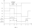
- FIG. 3 is a schematic diagram of control timing of a microgrid system according to this application.
- a grid voltage V mag of the external power grid does not drop, in other words, the external power grid does not fail.
- the grid-tied switch S1 is in an on state, and the power converter 111 is in a second current source control mode CS2.
- the grid voltage V mag of the external power grid drops, in other words, the external power grid fails, and the power converter 111 switches from the second current source control mode CS2 to a first current source control mode CS1.
- the grid-tied switch S1 is still in the on state.
- the grid voltage V mag of the external power grid does not recover, the failure of the external power grid persists, and the power converter 111 is in the first current source control mode CS1.
- the grid-tied switch S1 is still in the on state.
- the failure of the external power grid persists, and the power converter 111 switches from the first current source control mode CS1 to a first voltage source control mode VS1.
- the grid-tied switch S1 is still in the on state.
- the power converter 111 is in the first voltage source control mode VS1, and the grid-tied switch S1 is still in the on state.
- the microgrid controller 12 controls the grid-tied switch S1 to be turned off, a voltage of the microgrid system 1 recovers, and the power converter 111 is still in the first voltage source control mode VS1.
- the power converter 111 is still in the first voltage source control mode VS1, and the grid-tied switch S1 is in an off state.
- the grid voltage V mag of the external power grid recovers, the external power grid recovers, and the power converter 111 switches from the first voltage source control mode VS1 to a second voltage source control mode VS2.
- the grid-tied switch S1 is in the off state.
- the external power grid is normal, and the power converter 1111 is in the second voltage source control mode VS2, and controls an output voltage of the power converter 111 according to a synchronous control instruction sent by the microgrid controller 12.
- the grid-tied switch S1 is in the off state.
- the microgrid controller 12 controls the grid-tied switch S1 to be turned on, and determines an on/off state of the grid-tied switch S1 and a control mode for the power converter 111.
- the external power grid is normal, the power converter 111 is still in the second voltage source control mode VS2, and the grid-tied switch S1 is in the on state.
- the microgrid system 1 uses an on-grid/off-grid switching control mode with "a bottom-up means as a primary means and a top-down means as a secondary means".
- each power converter in the microgrid system 1 first determines whether a power grid fails, and then performs control mode switching, and then the microgrid controller 12 additionally sends a mode control instruction to each power converter based on an on/off state of the grid-tied switch S1 and a control mode for each power converter, so that each power converter performs both an on-grid/off-grid switching function and a failure ride-through support function during failure ride-through.
- the on-grid/off-grid switching control mode provided in this embodiment of this application has a low requirement on a communication delay between the micro grid controller 12 and each power converter. A large communication delay does not cause instability of the microgrid system 1, so that delay robustness is good.
- a controller included in the grid-tied switch S1 may directly control the grid-tied switch S1 to be turned on or turned off.
- control logic of controlling, by the controller of the grid-tied switch S1, the grid-tied switch S1 to be turned off or turned on is consistent with control logic of controlling, by the microgrid controller 12, the grid-tied switch S1 to be turned off or turned on. Details are not described herein again.
- the power converter is an energy storage converter is used below to verify that the microgrid system provided in this application performs both an on-grid/off-grid switching function and a failure ride-through support function during failure ride-through.
- FIG. 4 is a schematic diagram of simulation for a microgrid system according to this application.
- an upper curve and a lower curve in (a) in FIG. 4 represent a three-phase output voltage Vabc and a three-phase output current labc of each energy storage converter respectively
- (b) in FIG. 4 is a schematic enlarged view of a curve corresponding to a time period of 7.46s to 7.54s in (a) in FIG. 4 .
- each energy storage converter when operation time does not reach 7s, each energy storage converter is connected to the external power grid in a normal control mode in a current source control mode.
- operation time When operation time is 7s, a three-phase grounding failure occurs in the external power grid.
- operation time ranges from 7s to 7.5s each energy storage converter performs failure ride-through in the current source mode.
- each energy storage converter is in a current source failure ride-through control mode.
- operation time is 7.5s, each energy storage converter switches from the current source control mode to a voltage source control mode. Specifically, each energy storage converter switches from the current source failure ride-through control mode to a voltage source failure ride-through control mode.
- each energy storage converter When operation time ranges from 7.5s to 7.8s, each energy storage converter performs failure ride-through in the voltage source mode. To be specific, each energy storage converter is in a voltage source failure ride-through control mode. When operation time is 7.8s, the grid-tied switch is turned off, the microgrid system and the external power grid recover, and each energy storage converter operates in an off-grid mode. When operation time is greater than 7.8s, each energy storage converter independently operates with a load in a normal control mode in the voltage source control mode.
- each energy storage converter may switch from a first current source control mode to a first voltage source control mode during failure ride-through during which the external power grid fails, and perform both a failure ride-through support function and an on-grid/off-grid switching function.
- FIG. 5 is another schematic diagram of simulation for a microgrid system according to this application.
- an upper curve and a lower curve in (a) in FIG. 5 represent a three-phase output voltage Vabc and a three-phase output current labc of each energy storage converter respectively
- (b) in FIG. 5 is a schematic enlarged view of a curve corresponding to a time period of 7.46s to 7.54s in (a) in FIG. 5 .
- each energy storage converter when operation time does not reach 7s, each energy storage converter is connected to the external power grid in a normal control mode in a current source control mode.
- operation time When operation time is 7s, a three-phase grounding failure occurs at a point in the microgrid system.
- operation time ranges from 7s to 7.5s each energy storage converter performs failure ride-through in the current source mode.
- each energy storage converter is in a current source failure ride-through control mode.
- operation time is 7.5s, each energy storage converter switches from the current source control mode to a voltage source control mode. Specifically, each energy storage converter switches from the current source failure ride-through control mode to a voltage source failure ride-through control mode.
- each energy storage converter When operation time ranges from 7.5s to 7.8s, each energy storage converter performs failure ride-through in the voltage source mode. To be specific, each energy storage converter is in a voltage source failure ride-through control mode. When operation time is 7.8s, the grid-tied switch is turned off, and each energy storage converter operates in an off-grid mode. When operation time ranges from 7.8s to 8s, two energy storage converters continue to perform failure ride-through in the voltage source mode. When operation time is 8s, the failure is removed, and a voltage of the microgrid system recovers. When operation time is greater than 8s, each energy storage converter independently operates with a load in a normal control mode in the voltage source control mode.
- each energy storage converter may still switch from a first current source control mode to a first voltage source control mode during failure ride-through during which the microgrid system fails, and perform both a failure ride-through support function and an on-grid/off-grid switching function.
- FIG. 6 is still another schematic diagram of simulation for a microgrid system according to this application.
- two curves in an upper left part of FIG. 6 represent a three-phase output voltage Vabc and a three-phase output current labc of an energy storage converter PCS1 respectively
- two curves in a lower left part are schematic enlarged views of curves corresponding to a time period of 7.45s to 7.6s of the two curves in the upper left part of FIG. 6 respectively.
- FIG. 6 represent a three-phase output voltage Vabc and a three-phase output current labc of an energy storage converter PCS2 respectively, and two curves in a lower right part are schematic enlarged views of curves corresponding to a time period of 7.45s to 7.6s of the two curves in the upper right part of FIG. 6 respectively.
- each energy storage converter when operation time does not reach 7s, each energy storage converter is connected to the external power grid in a normal control mode in a current source control mode.
- operation time When operation time is 7s, a three-phase grounding failure occurs in the external power grid.
- operation time ranges from 7s to 7.5s each energy storage converter performs failure ride-through in the current source mode.
- each energy storage converter is in a current source failure ride-through control mode.
- operation time is 7.5s, the energy storage converter PCS1 switches from the current source control mode to a voltage source control mode. Specifically, each energy storage converter switches from the current source failure ride-through control mode to a voltage source failure ride-through control mode.
- the energy storage converter PCS1 When operation time ranges from 7.5s to 7.55s, the energy storage converter PCS1 performs failure ride-through in the voltage source mode, and the energy storage converter PCS2 performs failure ride-through in the current source mode.
- operation time When operation time is 7.55s, the energy storage converter PCS2 switches from the current source failure ride-through control mode to the voltage source failure ride-through control mode.
- operation time ranges from 7.55s to 7.8s
- both the energy storage converters PCS1 and PCS2 perform failure ride-through in the voltage source mode.
- operation time When operation time is 7.8s, the grid-tied switch is turned off, the failure is removed, and each energy storage converter operates in an off-grid mode.
- operation time When operation time is greater than 7.8s, each energy storage converter independently operates with a load in a normal operation mode in the voltage source control mode.
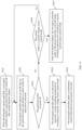
- FIG. 7 is a schematic flowchart of a control method for a power converter according to this application.
- the control method for a power converter in this embodiment of this application is applicable to the power converters in the microgrid system 1 shown in FIG. 2a and FIG. 2b .
- the control method for a power converter may include the following steps.
- the power grid includes an external power grid or a micro grid system.
- the first current source control mode is a current source failure ride-through control mode.
- the power converter controls an output voltage of the power converter based on a voltage drop value of a micro grid bus in a case in which the power grid fails.
- the power converter when the output voltage of the power converter is less than a voltage threshold or an output current of the power converter is greater than a current threshold, the power converter obtains a first reference output current value based on the voltage drop value of the microgrid bus in a case in which the power grid fails, and obtains a first reference output modulated voltage value based on the first reference output current value and a first reference angular frequency value, to control the output voltage of the power converter based on the first reference output modulated voltage value, so that the power converter is in the first current source control mode.
- the power converter switches from the first current source control mode to a first voltage source control mode, where the first duration is less than second duration, and the second duration is a time interval between a moment at which the power grid fails and a moment at which a grid-tied switch is turned off.
- the first voltage source control mode is a voltage source failure ride-through control mode.
- the power converter controls an output voltage of the power converter based on a maximum preset current amplitude in a preset current amplitude range.
- the power converter determines a second reference output current value based on the maximum preset current amplitude and an equivalent impedance angle of the external power grid, obtains a second reference output modulated voltage value based on the second reference output current value and a second reference angular frequency value, and controls the output voltage of the power converter based on the second reference output modulated voltage value, so that the power converter is in the first voltage source control mode and completes mode switching from the first current source control mode to the first voltage source control mode.
- the power converter determines, as an initial reference output current value and an initial reference angular frequency value of the power converter in the first voltage source control mode respectively, the first reference output current value and the first reference angular frequency value of the power converter in the first current source control mode at a switching moment at which the power converter switches from the first current source control mode to the first voltage source control mode; and obtains the second reference output modulated voltage value based on the initial reference output current value and the initial reference angular frequency value, to control the output voltage of the power converter based on the second reference output modulated voltage value, so that the power converter switches from the first current source control mode to the first voltage source control mode.
- the power converter when the power grid fails, controls the power converter to be in the current source failure ride-through control mode when detecting that the power grid fails, and controls the power converter to switch to the voltage source failure ride-through control mode before the grid-tied switch is turned off, so that the power converter provides voltage support for the external power grid when the power grid fails, and completes on-grid/off-grid mode switching before the grid-tied switch is turned off.
- the power converter performs both a failure ride-through support function and an on-grid/off-grid switching function.
- FIG. 8A and FIG. 8B are another schematic flowchart of a control method for a power converter according to this application.
- the control method for a power converter in this embodiment of this application is applicable to the power converters in the microgrid system 1 shown in FIG. 2a and FIG. 2b .
- the control method for a power converter may include the following steps.
- the power converter controls an output voltage of the power converter based on a reference output active current value and a reference output reactive current value.
- the power converter determines the reference output active current value and the reference output reactive current value as a third reference output current value, and obtains a third reference output modulated voltage value based on the third reference output current value and a third reference angular frequency value, to control the output voltage of the power converter based on the third reference output modulated voltage value, so that the power converter is in the second current source control mode.
- S202 The power converter determines whether a power grid fails.
- the power converter determines that the power grid fails.
- the power grid includes an external power grid or the microgrid system.
- step S203 when determining that the power grid fails, the power converter performs step S203; otherwise, the power converter performs step S201.
- S203 The power converter is in a first current source control mode.
- the power converter obtains a first reference output current value based on a voltage drop value of the micro grid bus in a case in which the power grid fails, and obtains a first reference output modulated voltage value based on the first reference output current value and a first reference angular frequency value, to control the output voltage of the power converter based on the first reference output modulated voltage value, so that the power converter is in the first current source control mode.
- S204 The power converter determines whether the power grid recovers.
- the power converter determines that the power grid recovers.
- the power converter determines that the power grid recovers.
- the power converter determines that the power grid recovers.
- the power converter determines that the power grid recovers.
- step S201 when determining that the power grid recovers, the power converter performs step S201; otherwise, the power converter performs step S205.
- S205 The power converter determines whether duration of the power grid failure reaches first duration.
- the first duration is less than second duration.
- the second duration is a time interval between a moment at which the power grid fails and a moment at which a grid-tied switch is turned off.
- the power converter after determining that the duration of the power grid failure reaches the first duration, the power converter performs step S206; otherwise, the power converter performs step S203.
- S206 The power converter switches from the first current source control mode to a first voltage source control mode.
- the power converter controls an output voltage of the power converter based on a maximum preset current amplitude in a preset current amplitude range.
- the power converter determines a second reference output current value based on the maximum preset current amplitude and an equivalent impedance angle of the external power grid, obtains a second reference output modulated voltage value based on the second reference output current value and a second reference angular frequency value, and controls the output voltage of the power converter based on the second reference output modulated voltage value, so that the power converter is in the first voltage source control mode and completes switching from the first current source control mode to the first voltage source control mode.
- the power converter determines, as an initial reference output current value and an initial reference angular frequency value of the power converter in the first voltage source control mode respectively, the first reference output current value and the first reference angular frequency value of the power converter in the first current source control mode at a switching moment at which the power converter switches from the first current source control mode to the first voltage source control mode; and obtains the second reference output modulated voltage value based on the initial reference output current value and the initial reference angular frequency value, to control the output voltage of the power converter based on the second reference output modulated voltage value, so that the power converter switches from the first current source control mode to the first voltage source control mode.
- S207 The power converter determines whether the power grid recovers.
- the power converter When determining that the power grid recovers, the power converter performs step S208; otherwise, the power converter performs step S206.
- the power converter switches from the first voltage source control mode to a second voltage source control mode, and sends a control mode for the power converter to a microgrid controller.
- the power converter controls an output voltage of the power converter based on a reference voltage amplitude and a reference frequency value.
- the power converter obtains a fourth reference output modulated voltage value based on the reference voltage amplitude and the reference frequency value, and controls the output voltage of the power converter based on the fourth reference output modulated voltage value, so that the power converter is in the second voltage source control mode and completes switching from the first voltage source control mode to the second voltage source control mode.
- the power converter sends the control mode for the power converter to the micro grid controller.
- S209 The power converter determines whether a mode switching instruction is received.
- the power converter When receiving the mode switching instruction, the power converter performs step S210; otherwise, the power converter performs step S208.
- S210 The power converter determines whether the mode switching instruction is an instruction for switching to the second current source control mode.
- the power converter When the mode switching instruction is an instruction for switching to the second current source control mode, the power converter performs step S212; otherwise, the power converter performs step S211.
- S211 The power converter switches from the second voltage source control mode to the second current source control mode.
- the power converter controls an output voltage of the power converter based on a reference output active current value and a reference output reactive current value.
- the power converter determines the reference output active current value and the reference output reactive current value as a third reference output current value, and obtains a third reference output modulated voltage value based on the third reference output current value and a third reference angular frequency value, to control the output voltage of the power converter based on the third reference output modulated voltage value, so that the power converter is in the second current source control mode and completes switching from the second voltage source control mode to the second current source control mode.
- S212 The power converter is in the second voltage source control mode.
- step S212 for a specific implementation of step S212, refer to the descriptions of step S201. Details are not described herein again.
- each power converter in the microgrid system completes switching from the failure ride-through control mode in the current source control mode to the failure ride-through control mode in the voltage source control mode before the grid-tied switch is turned off.
- each power converter performs both an on-grid/off-grid switching function and a failure ride-through support function during failure ride-through.
- dependence on communication delay performance is significantly reduced, and the power converter is prevented from injecting a disturbance signal into the external power grid to detect an off-grid state. This resolves instability of the microgrid system caused by a large switching delay of the power converter.
- FIG. 9 is a schematic flowchart of a control method for a micro grid controller according to this application.
- the control method for a micro grid controller in this embodiment of this application is applicable to the micro grid controller 12 shown in FIG. 2a and FIG. 2b .
- the control method for a micro grid controller may include the following steps.
- a micro grid controller When detecting that a power grid fails, a micro grid controller controls a grid-tied switch to be turned off after second duration elapses.
- the power grid includes an external power grid or a microgrid system.
- the microgrid controller controls the grid-tied switch to be turned off after the second duration elapses.
- the micro grid controller detects an on/off state of the grid-tied switch, and obtains a control mode for each power converter.
- S303 The microgrid controller determines whether the grid-tied switch is turned off.
- step S304 When the grid-tied switch is turned off, the micro grid controller performs step S304; otherwise, the micro grid controller performs step S306.
- S304 The micro grid controller sends, to each power converter, a mode switching instruction for switching to a second voltage source control mode.
- the mode switching instruction for switching to the second voltage source control mode is used to control each power converter to switch to the second voltage source control mode.
- S305 The microgrid controller sends a synchronous control instruction to each power converter.
- the synchronous control instruction is used to control an amplitude difference between an output voltage amplitude of the power converter and a voltage amplitude of the external power grid to be less than an amplitude difference threshold, and a phase difference between an output voltage phase of the power converter and a voltage phase of the external power grid to be less than a phase difference threshold.
- S306 The micro grid controller determines whether the control mode for the power converter is the second voltage source control mode.
- the micro grid controller When the control mode for the power converter is the second voltage source control mode, the micro grid controller performs step S307; otherwise, the microgrid controller performs step S302.
- the second mode switching instruction for switching to the second current source control mode is used to control the power converter to switch to the second current source control mode.
- the microgrid controller adjusts the control mode for each power converter based on the on/off state of the grid-tied switch and the control mode for each power converter, so that each power converter operates in a current source control mode when the microgrid system is in an on-grid mode, and operates in a voltage source control mode when the microgrid system is in an off-grid mode, to improve stability of the microgrid system.
Landscapes
- Engineering & Computer Science (AREA)
- Power Engineering (AREA)
- Inverter Devices (AREA)
Applications Claiming Priority (2)
| Application Number | Priority Date | Filing Date | Title |
|---|---|---|---|
| CN202310150573.1A CN116231636A (zh) | 2023-02-07 | 2023-02-07 | 微电网系统、功率变换器及其控制方法 |
| PCT/CN2024/072527 WO2024164811A1 (zh) | 2023-02-07 | 2024-01-16 | 微电网系统、功率变换器及其控制方法 |
Publications (2)
| Publication Number | Publication Date |
|---|---|
| EP4439902A1 true EP4439902A1 (de) | 2024-10-02 |
| EP4439902A4 EP4439902A4 (de) | 2025-04-30 |
Family
ID=86569105
Family Applications (1)
| Application Number | Title | Priority Date | Filing Date |
|---|---|---|---|
| EP24710010.0A Pending EP4439902A4 (de) | 2023-02-07 | 2024-01-16 | Mikronetzsystem, stromwandler und steuerungsverfahren dafür |
Country Status (3)
| Country | Link |
|---|---|
| EP (1) | EP4439902A4 (de) |
| CN (1) | CN116231636A (de) |
| WO (1) | WO2024164811A1 (de) |
Families Citing this family (3)
| Publication number | Priority date | Publication date | Assignee | Title |
|---|---|---|---|---|
| CN116231636A (zh) * | 2023-02-07 | 2023-06-06 | 华为数字能源技术有限公司 | 微电网系统、功率变换器及其控制方法 |
| CN117937590A (zh) * | 2023-12-18 | 2024-04-26 | 华为数字能源技术有限公司 | 用于微电网系统的控制装置,控制方法和微电网系统 |
| CN118971122A (zh) * | 2024-07-10 | 2024-11-15 | 华为数字能源技术有限公司 | 发电系统、逆变器以及发电系统的并离网切换方法 |
Family Cites Families (7)
| Publication number | Priority date | Publication date | Assignee | Title |
|---|---|---|---|---|
| CN104201706A (zh) * | 2014-09-04 | 2014-12-10 | 北京艾科迈新能源科技有限公司 | 一种兼顾故障穿越与并离网无缝切换的储能协调控制方法 |
| CN105552962B (zh) * | 2016-02-01 | 2018-10-19 | 易事特集团股份有限公司 | 微电网系统及其控制方法 |
| CN107994603B (zh) * | 2017-11-02 | 2020-07-21 | 许继电气股份有限公司 | 一种基于虚拟同步发电机故障穿越控制方法及系统 |
| CN109617075A (zh) * | 2018-12-13 | 2019-04-12 | 天津大学 | 一种多功能双向功率变换器的控制方法 |
| CN110048455B (zh) * | 2019-04-24 | 2021-06-01 | 湖南大学 | 具有弱电网故障穿越能力的下垂控制逆变器及其控制方法 |
| CN115296342B (zh) * | 2022-08-30 | 2024-10-15 | 南方电网科学研究院有限责任公司 | 一种新能源孤岛电网交流故障下送端系统协调控制方法 |
| CN116231636A (zh) * | 2023-02-07 | 2023-06-06 | 华为数字能源技术有限公司 | 微电网系统、功率变换器及其控制方法 |
-
2023
- 2023-02-07 CN CN202310150573.1A patent/CN116231636A/zh active Pending
-
2024
- 2024-01-16 WO PCT/CN2024/072527 patent/WO2024164811A1/zh not_active Ceased
- 2024-01-16 EP EP24710010.0A patent/EP4439902A4/de active Pending
Also Published As
| Publication number | Publication date |
|---|---|
| EP4439902A4 (de) | 2025-04-30 |
| CN116231636A (zh) | 2023-06-06 |
| WO2024164811A1 (zh) | 2024-08-15 |
| US20240305096A1 (en) | 2024-09-12 |
Similar Documents
| Publication | Publication Date | Title |
|---|---|---|
| EP4439902A1 (de) | Mikronetzsystem, stromwandler und steuerungsverfahren dafür | |
| US9660453B2 (en) | Control of a microgrid | |
| CN107437821B (zh) | 孤岛微电网虚拟机差异化故障穿越系统及其实现方法 | |
| US10784683B2 (en) | Method of controlling electrical power system and apparatus using the same | |
| EP3324509A1 (de) | Stromversorgungssystem und stromversorgungsverfahren | |
| EP2731222B1 (de) | Verfahren und vorrichtung zur blindleistungskompensation in einem stromnetz und wechselrichter | |
| Bisht et al. | Active and reactive power control of single phase inverter with seamless transfer between grid-connected and islanded mode | |
| EP4432545A1 (de) | Wechselrichter und steuerungsverfahren dafür | |
| EP4290727A1 (de) | Energiespeichersystem und schwarzstartverfahren | |
| EP4312335A2 (de) | Wandler, netzstromversorgungssystem und wandlersteuerungsverfahren | |
| US20180342869A1 (en) | Alternating current/direct current home smart micro-grid coordination system and operation method thereof | |
| EP4593280A1 (de) | Energiespeichersystem und inselerkennungsverfahren | |
| EP4125174B1 (de) | Energiespeichersystem und netzwerk/inselumschaltverfahren | |
| KR101646170B1 (ko) | 계통연계운전 및 독립운전을 수행하는 전력시스템 제어 방법 | |
| CN105470997A (zh) | 一种微电网控制系统 | |
| CN107769247B (zh) | 一种用于防孤岛检测的rlc负载模拟系统及其控制方法 | |
| CN104979846B (zh) | 一种多电平逆变器低电压穿越控制方法、设备及系统 | |
| US12483158B2 (en) | Power supply system, inverter, and method for controlling positive and negative bus voltages of inverter | |
| CN113013917B (zh) | 用于电力电子变流器的混合型相位同步控制器及控制方法 | |
| JP6208573B2 (ja) | 電力制御装置および電力制御方法 | |
| US12555999B2 (en) | Microgrid system, power converter, and control method for power converter | |
| CN102868213B (zh) | 后备式不间断电源无延时同步切换电路及方法 | |
| EP4456366A1 (de) | Stromversorgungssystem und verfahren zum starten des stromversorgungssystems | |
| EP4580030A1 (de) | Fotovoltaischer wechselrichter und steuerungsverfahren dafür | |
| KR100964138B1 (ko) | 계통연계형 차단장치 및 보호방법 |
Legal Events
| Date | Code | Title | Description |
|---|---|---|---|
| STAA | Information on the status of an ep patent application or granted ep patent |
Free format text: STATUS: UNKNOWN |
|
| STAA | Information on the status of an ep patent application or granted ep patent |
Free format text: STATUS: THE INTERNATIONAL PUBLICATION HAS BEEN MADE |
|
| PUAI | Public reference made under article 153(3) epc to a published international application that has entered the european phase |
Free format text: ORIGINAL CODE: 0009012 |
|
| STAA | Information on the status of an ep patent application or granted ep patent |
Free format text: STATUS: REQUEST FOR EXAMINATION WAS MADE |
|
| 17P | Request for examination filed |
Effective date: 20240315 |
|
| AK | Designated contracting states |
Kind code of ref document: A1 Designated state(s): AL AT BE BG CH CY CZ DE DK EE ES FI FR GB GR HR HU IE IS IT LI LT LU LV MC ME MK MT NL NO PL PT RO RS SE SI SK SM TR |
|
| A4 | Supplementary search report drawn up and despatched |
Effective date: 20250331 |
|
| RIC1 | Information provided on ipc code assigned before grant |
Ipc: H02J 3/38 20060101ALI20250325BHEP Ipc: H02J 3/32 20060101ALI20250325BHEP Ipc: H02J 3/12 20060101ALI20250325BHEP Ipc: H02J 3/00 20060101AFI20250325BHEP |