EP4439833A1 - Tray assembly, power battery pack, and vehicle - Google Patents
Tray assembly, power battery pack, and vehicle Download PDFInfo
- Publication number
- EP4439833A1 EP4439833A1 EP23769805.5A EP23769805A EP4439833A1 EP 4439833 A1 EP4439833 A1 EP 4439833A1 EP 23769805 A EP23769805 A EP 23769805A EP 4439833 A1 EP4439833 A1 EP 4439833A1
- Authority
- EP
- European Patent Office
- Prior art keywords
- tray assembly
- bushing
- expansion
- cavity
- carrying
- Prior art date
- Legal status (The legal status is an assumption and is not a legal conclusion. Google has not performed a legal analysis and makes no representation as to the accuracy of the status listed.)
- Pending
Links
Images


Classifications
-
- H—ELECTRICITY
- H01—ELECTRIC ELEMENTS
- H01M—PROCESSES OR MEANS, e.g. BATTERIES, FOR THE DIRECT CONVERSION OF CHEMICAL ENERGY INTO ELECTRICAL ENERGY
- H01M50/00—Constructional details or processes of manufacture of the non-active parts of electrochemical cells other than fuel cells, e.g. hybrid cells
- H01M50/20—Mountings; Secondary casings or frames; Racks, modules or packs; Suspension devices; Shock absorbers; Transport or carrying devices; Holders
- H01M50/262—Mountings; Secondary casings or frames; Racks, modules or packs; Suspension devices; Shock absorbers; Transport or carrying devices; Holders with fastening means, e.g. locks
-
- H—ELECTRICITY
- H01—ELECTRIC ELEMENTS
- H01M—PROCESSES OR MEANS, e.g. BATTERIES, FOR THE DIRECT CONVERSION OF CHEMICAL ENERGY INTO ELECTRICAL ENERGY
- H01M50/00—Constructional details or processes of manufacture of the non-active parts of electrochemical cells other than fuel cells, e.g. hybrid cells
- H01M50/20—Mountings; Secondary casings or frames; Racks, modules or packs; Suspension devices; Shock absorbers; Transport or carrying devices; Holders
- H01M50/204—Racks, modules or packs for multiple batteries or multiple cells
-
- H—ELECTRICITY
- H01—ELECTRIC ELEMENTS
- H01M—PROCESSES OR MEANS, e.g. BATTERIES, FOR THE DIRECT CONVERSION OF CHEMICAL ENERGY INTO ELECTRICAL ENERGY
- H01M50/00—Constructional details or processes of manufacture of the non-active parts of electrochemical cells other than fuel cells, e.g. hybrid cells
- H01M50/20—Mountings; Secondary casings or frames; Racks, modules or packs; Suspension devices; Shock absorbers; Transport or carrying devices; Holders
- H01M50/218—Mountings; Secondary casings or frames; Racks, modules or packs; Suspension devices; Shock absorbers; Transport or carrying devices; Holders characterised by the material
- H01M50/22—Mountings; Secondary casings or frames; Racks, modules or packs; Suspension devices; Shock absorbers; Transport or carrying devices; Holders characterised by the material of the casings or racks
-
- H—ELECTRICITY
- H01—ELECTRIC ELEMENTS
- H01M—PROCESSES OR MEANS, e.g. BATTERIES, FOR THE DIRECT CONVERSION OF CHEMICAL ENERGY INTO ELECTRICAL ENERGY
- H01M50/00—Constructional details or processes of manufacture of the non-active parts of electrochemical cells other than fuel cells, e.g. hybrid cells
- H01M50/20—Mountings; Secondary casings or frames; Racks, modules or packs; Suspension devices; Shock absorbers; Transport or carrying devices; Holders
- H01M50/233—Mountings; Secondary casings or frames; Racks, modules or packs; Suspension devices; Shock absorbers; Transport or carrying devices; Holders characterised by physical properties of casings or racks, e.g. dimensions
- H01M50/242—Mountings; Secondary casings or frames; Racks, modules or packs; Suspension devices; Shock absorbers; Transport or carrying devices; Holders characterised by physical properties of casings or racks, e.g. dimensions adapted for protecting batteries against vibrations, collision impact or swelling
-
- H—ELECTRICITY
- H01—ELECTRIC ELEMENTS
- H01M—PROCESSES OR MEANS, e.g. BATTERIES, FOR THE DIRECT CONVERSION OF CHEMICAL ENERGY INTO ELECTRICAL ENERGY
- H01M50/00—Constructional details or processes of manufacture of the non-active parts of electrochemical cells other than fuel cells, e.g. hybrid cells
- H01M50/20—Mountings; Secondary casings or frames; Racks, modules or packs; Suspension devices; Shock absorbers; Transport or carrying devices; Holders
- H01M50/244—Secondary casings; Racks; Suspension devices; Carrying devices; Holders characterised by their mounting method
-
- H—ELECTRICITY
- H01—ELECTRIC ELEMENTS
- H01M—PROCESSES OR MEANS, e.g. BATTERIES, FOR THE DIRECT CONVERSION OF CHEMICAL ENERGY INTO ELECTRICAL ENERGY
- H01M50/00—Constructional details or processes of manufacture of the non-active parts of electrochemical cells other than fuel cells, e.g. hybrid cells
- H01M50/20—Mountings; Secondary casings or frames; Racks, modules or packs; Suspension devices; Shock absorbers; Transport or carrying devices; Holders
- H01M50/249—Mountings; Secondary casings or frames; Racks, modules or packs; Suspension devices; Shock absorbers; Transport or carrying devices; Holders specially adapted for aircraft or vehicles, e.g. cars or trains
-
- H—ELECTRICITY
- H01—ELECTRIC ELEMENTS
- H01M—PROCESSES OR MEANS, e.g. BATTERIES, FOR THE DIRECT CONVERSION OF CHEMICAL ENERGY INTO ELECTRICAL ENERGY
- H01M50/00—Constructional details or processes of manufacture of the non-active parts of electrochemical cells other than fuel cells, e.g. hybrid cells
- H01M50/20—Mountings; Secondary casings or frames; Racks, modules or packs; Suspension devices; Shock absorbers; Transport or carrying devices; Holders
- H01M50/262—Mountings; Secondary casings or frames; Racks, modules or packs; Suspension devices; Shock absorbers; Transport or carrying devices; Holders with fastening means, e.g. locks
- H01M50/264—Mountings; Secondary casings or frames; Racks, modules or packs; Suspension devices; Shock absorbers; Transport or carrying devices; Holders with fastening means, e.g. locks for cells or batteries, e.g. straps, tie rods or peripheral frames
-
- H—ELECTRICITY
- H01—ELECTRIC ELEMENTS
- H01M—PROCESSES OR MEANS, e.g. BATTERIES, FOR THE DIRECT CONVERSION OF CHEMICAL ENERGY INTO ELECTRICAL ENERGY
- H01M50/00—Constructional details or processes of manufacture of the non-active parts of electrochemical cells other than fuel cells, e.g. hybrid cells
- H01M50/20—Mountings; Secondary casings or frames; Racks, modules or packs; Suspension devices; Shock absorbers; Transport or carrying devices; Holders
- H01M50/271—Lids or covers for the racks or secondary casings
-
- H—ELECTRICITY
- H01—ELECTRIC ELEMENTS
- H01M—PROCESSES OR MEANS, e.g. BATTERIES, FOR THE DIRECT CONVERSION OF CHEMICAL ENERGY INTO ELECTRICAL ENERGY
- H01M50/00—Constructional details or processes of manufacture of the non-active parts of electrochemical cells other than fuel cells, e.g. hybrid cells
- H01M50/20—Mountings; Secondary casings or frames; Racks, modules or packs; Suspension devices; Shock absorbers; Transport or carrying devices; Holders
- H01M50/289—Mountings; Secondary casings or frames; Racks, modules or packs; Suspension devices; Shock absorbers; Transport or carrying devices; Holders characterised by spacing elements or positioning means within frames, racks or packs
-
- H—ELECTRICITY
- H01—ELECTRIC ELEMENTS
- H01M—PROCESSES OR MEANS, e.g. BATTERIES, FOR THE DIRECT CONVERSION OF CHEMICAL ENERGY INTO ELECTRICAL ENERGY
- H01M2220/00—Batteries for particular applications
- H01M2220/20—Batteries in motive systems, e.g. vehicle, ship, plane
-
- Y—GENERAL TAGGING OF NEW TECHNOLOGICAL DEVELOPMENTS; GENERAL TAGGING OF CROSS-SECTIONAL TECHNOLOGIES SPANNING OVER SEVERAL SECTIONS OF THE IPC; TECHNICAL SUBJECTS COVERED BY FORMER USPC CROSS-REFERENCE ART COLLECTIONS [XRACs] AND DIGESTS
- Y02—TECHNOLOGIES OR APPLICATIONS FOR MITIGATION OR ADAPTATION AGAINST CLIMATE CHANGE
- Y02E—REDUCTION OF GREENHOUSE GAS [GHG] EMISSIONS, RELATED TO ENERGY GENERATION, TRANSMISSION OR DISTRIBUTION
- Y02E60/00—Enabling technologies; Technologies with a potential or indirect contribution to GHG emissions mitigation
- Y02E60/10—Energy storage using batteries
Definitions
- the present disclosure relates to the field of vehicle technologies, and in particular, to a tray assembly, a power battery pack, and a vehicle.
- sealing performance of a power battery pack is poor and hardly meets a design requirement.
- a sealing arrangement of the power battery pack is complex.
- the present disclosure aims to resolve at least one of the technical problems existing in the related art. Therefore, the present disclosure provides a tray assembly.
- the tray assembly has good sealing performance, to meet a sealing requirement of a power battery pack.
- the present disclosure further provides a power battery pack including the foregoing tray assembly.
- the present disclosure further provides a vehicle including the foregoing power battery pack.
- the tray assembly includes: a bottom plate, where the bottom plate includes a main body portion and a raised edge portion, the main body portion defines an accommodating cavity, the accommodating cavity is configured to accommodate a battery, and the raised edge portion is located on a peripheral side of the main body portion and arranged around the main body portion; an expansion beam, where the expansion beam is arranged on one side of the raised edge portion in a thickness direction, and the expansion beam is adapted to abut with the battery; and a first sealing member, where the first sealing member includes a first portion, and the first portion is arranged between the expansion beam and the raised edge portion.
- the tray assembly provides the first sealing member between the expansion beam and the raised edge portion, to seal a gap between the raised edge portion and the expansion beam, so that the sealing performance of the tray assembly is improved. In this way, it is easy to meet a sealing requirement of the power battery pack.
- the tray assembly further includes: a side frame, where the side frame is located on a peripheral side of the bottom plate and arranged around the main body portion, the side frame includes multiple side beams connected end to end in sequence, the side beam is located on the other side of the raised edge portion in the thickness direction and fixed to the raised edge portion, and the raised edge portion forms a first avoiding hole; and a fastener, where the fastener penetrates the first avoiding hole and fixedly connects the expansion beam to a corresponding side beam, and the first portion is arranged around the first avoiding hole.
- the first sealing member further includes a second portion, and the second portion is sealed between the fastener and a peripheral wall of the first avoiding hole.
- the side frame further includes a bushing.
- the bushing penetrates the first avoiding hole and is fixed to the side beam.
- the bushing forms a connecting hole.
- the fastener is fixedly fitted with the connecting hole.
- the first sealing member further includes a third portion, and the third portion is sealed between the bushing and a peripheral wall of the first avoiding hole.
- the tray assembly further includes: a second sealing member, where the second sealing member includes a fourth portion, and the fourth portion is arranged between the side beam and the raised edge portion.
- the fourth portion is arranged around the fastener.
- the side frame further includes the bushing.
- the side beam forms a second avoiding hole.
- the bushing is fixed to the side beam and at least a portion of the bushing is located on one side of the second avoiding hole facing away from the raised edge portion.
- the bushing forms a connecting hole. The fastener penetrates the second avoiding hole and is fixedly fitted with the connecting hole.
- one end of the bushing protrudes from one side of the raised edge portion facing the expansion beam and abuts against the expansion beam.
- the bushing and a peripheral wall of the second avoiding hole are welded and fixed, and the second sealing member covers a welding seam at the second avoiding hole.
- the first sealing member includes the third portion, and the third portion is sealed between the bushing and the peripheral wall of the first avoiding hole; and/or the second sealing member includes a fifth portion, and the fifth portion is sealed between the bushing and the peripheral wall of the first avoiding hole.
- a region of the bushing that abuts against the expansion beam is an annular region, and a radial distance between an outer circumferential edge and an inner circumferential edge of the annular region is greater than or equal to 1 mm.
- either of the first sealing member and the second sealing member is a structural adhesive
- a thickness of the structural adhesive is t, where 0.5 mm ⁇ t ⁇ 1 mm.
- the bottom plate is an insulating material member.
- the expansion beam includes a carrying beam and a partition plate.
- the carrying beam defines a carrying cavity.
- the partition plate is arranged in the carrying cavity to separate the carrying cavity into a first carrying cavity and a second carrying cavity.
- the first carrying cavity is located on one side of the second carrying cavity facing away from the raised edge portion.
- the tray assembly further includes the fastener.
- the expansion beam further includes: a support member, where the support member is arranged in the second carrying cavity, the support member supports one cavity wall of the second carrying cavity away from the partition plate and the partition plate, and the fastener penetrates the partition plate and the second carrying cavity and extends out of the second carrying cavity to fix the expansion beam to the side beam.
- the support member includes multiple support blocks.
- the multiple support blocks are arranged spaced away along a length direction of the carrying beam. Each fastener penetrates a corresponding support block.
- an area of a cross section of the support member is s1
- an area of a cross section of the second carrying cavity is s2, where 50% ⁇ s1/s2 ⁇ 60%. Either of the cross section of the support member and the cross section of the second carrying cavity is perpendicular to the length direction of the carrying beam.
- one cavity wall of the second carrying cavity away from the first carrying cavity forms a mounting through hole.
- the support member is arranged in the second carrying cavity. One end of the support member abuts against the partition plate, and the other end of the support member is fitted with the mounting through hole and fixedly connected to the cavity wall of the second carrying cavity away from the partition plate.
- the side frame includes the bushing.
- the bushing is fixedly connected to the expansion beam and the fastener separately, and one end of the bushing adjacent to the expansion beam abuts against the support member.
- a power battery pack includes a battery, a sealing cover, and the tray assembly according to the embodiments of the first aspect of the present disclosure.
- the sealing cover covers an open side of the accommodating cavity and together with the tray assembly defines a mounting space.
- the battery is provided in the mounting space.
- the power battery pack uses the foregoing tray assembly, to meet a sealing requirement of the power battery pack.
- multiple batteries exist, and the multiple batteries are arranged in a first direction in sequence.
- Each of the batteries extends along a second direction.
- a quantity of expansion beams is two, and the two expansion beams are respectively arranged on two sides of the multiple batteries in the first direction. Either of the expansion beams extends along the second direction.
- the second direction is perpendicular to the first direction.
- a vehicle includes the power battery pack according to the embodiments of the second aspect of the present disclosure.
- the vehicle uses the foregoing power battery pack, to ensure safe use of the vehicle.
- the disclosure below provides many different embodiments or examples for implementing different structures of the present disclosure.
- the following describes components and settings of specific examples.
- the components and settings are merely examples, and are not intended to limit the present disclosure.
- reference numerals and/or letters may be repeated in different examples in the present disclosure. Such repetitions are for simplification and clarity, which do not indicate relationships between the embodiments and/or settings discussed.
- the present disclosure provides examples of various specific processes and materials, but a person of ordinary skill in the art may be aware of the applicability of other processes and/or the use of other materials.
- the tray assembly 1 includes a bottom plate 111.
- the bottom plate 111 includes a main body portion 1111 and a raised edge portion 1112.
- the main body portion 1111 defines an accommodating cavity 110.
- the accommodating cavity 110 is configured to accommodate a battery 2. This facilitates ensuring stable mounting of the battery 2, and in addition, the bottom plate 111 can protect the battery 2.
- the raised edge portion 1112 is located on a peripheral side of the main body portion 1111, and the raised edge portion 1112 is arranged around the main body portion 1111. In this way, the raised edge portion 1112 can generally define an annular structure.
- annular is to be understood in a broad sense, that is, not limited to “circular ring”.
- it may alternatively be “polygonal ring”.
- the tray assembly 1 further includes an expansion beam 12.
- the expansion beam (12) is arranged on one side of the raised edge portion (1112) in a thickness direction.
- the expansion beam (12) is adapted to abut with the battery (2).
- the expansion beam 12 may be in direct contact with the battery 2, or another component may be arranged between the expansion beam 12 and the battery 2 to make the expansion beam 12 indirectly abut against the battery 2. This facilitates the expansion beam 12 to withstand expansion force of the battery 2.
- the expansion beam 12 and the bottom plate 111 are separately processed members.
- the tray assembly 1 further includes a first sealing member 141.
- the first sealing member 141 includes a first portion 141a.
- the first portion 141a is arranged between the expansion beam 12 and the raised edge portion 1112.
- a portion of the first sealing member 141 is arranged between the expansion beam 12 and the raised edge portion 1112, or the entire first sealing member 141 is arranged between the expansion beam 12 and the raised edge portion 1112, to seal a gap between the expansion beam 12 and the raised edge portion 1112, so that the tray assembly 1 has good sealing performance.
- the tray assembly 1 when used in a power battery pack 100, it is easy to meet a sealing requirement of the power battery pack 100, to ensure that the power battery pack 100 has good performance such as dustproof and waterproof.
- the first sealing member 141 is arranged conveniently, and has a large operating space.
- the tray assembly 1 provides the first portion 141a of the first sealing member 141 between the expansion beam 12 and the raised edge portion 1112, to seal the gap between the raised edge portion 1112 and the expansion beam 12, so that the sealing performance of the tray assembly 1 is improved. In this way, it is easy to meet the sealing requirement of the power battery pack 100.
- the tray assembly 1 further includes a side frame 112.
- the side frame 112 is located on a peripheral side of the bottom plate 111, and the side frame 112 is arranged around the main body portion 1111.
- the side frame 112 includes multiple side beams 1121 connected end to end in sequence, so that the side frame 112 defines an annular structure to facilitate the side frame 112 to stably support the bottom plate 111.
- the side beam 1121 is located on the other side of the raised edge portion 1112 in the thickness direction, and the side beam 1121 is fixed to the raised edge portion 1112, so that the expansion beam 12 and the side beam 1121 are located on different sides of the thickness of the raised edge portion 1112.
- the side beam 1121 is a rolled steel member.
- the side beam 1121 may alternatively be an aluminum member.
- the raised edge portion 1112 forms a first avoiding hole 1112a.
- the tray assembly 1 further includes a fastener 13.
- the fastener 13 penetrates the first avoiding hole 1112a, and the fastener 13 fixedly connects the expansion beam 12 to the side beam 1121, so that the first avoiding hole 1112a can avoid the fastener 13, to ensure that the expansion beam 12 is smoothly fixed to a corresponding side beam 1121 through the fastener 13.
- the first portion 141a is arranged around the first avoiding hole 1112a, to be specific, a portion of the first sealing member 141 between the expansion beam 12 and the raised edge portion 1112 is arranged around the first avoiding hole 1112a.
- the first sealing member 141 further includes a second portion, and the second portion is sealed between the fastener 13 and a peripheral wall of the first avoiding hole 1112a.
- the first sealing member 141 ensures sealing between the expansion beam 12 and the raised edge portion 1112, and also ensures sealing between the fastener 13 and the raised edge portion 1112, further improving the sealing performance of the tray assembly 1.
- the first sealing member 141 is a structural adhesive.
- the structural adhesive has good strength, corrosion resistance, and stable performance, to ensure service life of the tray assembly 1.
- a thickness of the first sealing member 141 is 11, where 0.5 mm ⁇ t1 ⁇ 1 mm. In this way, difficulty in controlling a processing process caused by an excessively small thickness of the first sealing member 141 can be avoided, and impact on a bonding effect of the structural adhesive caused by an excessively large thickness of the first sealing member 141 can also be avoided.
- the thickness of the first sealing member 141 may be 0.5 mm, 0.7 mm, 0.8 mm, or 1 mm.
- the first sealing member 141 may alternatively be a sealing ring, for example, a rubber ring.
- the structural adhesive when the first sealing member 141 is a structural adhesive, the structural adhesive is in a liquid state during a process of assembling the tray assembly 1.
- the structural adhesive is arranged between the expansion beam 12 and the raised edge portion 1112. Through extrusion between the expansion beam 12 and the raised edge portion 1112, the structural adhesive easily overflows between the fastener 13 and the first avoiding hole 1112a. Therefore, when the structural adhesive cures to form the first sealing member 141, it is easy to seal the first portion 141a of the first sealing member 141 between the expansion beam 12 and the raised edge portion 1112, and seal the second portion of the first sealing member 141 between the fastener 13 and the first avoiding hole 1112a.
- the side frame 112 further includes a bushing 1122.
- the bushing 1122 penetrates the first avoiding hole 1112a, and the bushing 1122 is fixed to the side beam 1121.
- the bushing 1122 forms a connecting hole 1122a.
- the fastener 13 is fixedly fitted with the connecting hole 1122a.
- the first sealing member 141 further includes a third portion 141c.
- the third portion 141c is sealed between the bushing 1122 and a peripheral wall of the first avoiding hole 1112a, to implement sealing between the bushing 1122 and the raised edge portion 1112, further improving the sealing performance of the tray assembly 1.
- the bushing 1122 may penetrate the first avoiding hole 1112a.
- the tray assembly 1 further includes a second sealing member 142.
- the second sealing member 142 includes a fourth portion 142a.
- the fourth portion 142a is arranged between the side beam 1121 and the raised edge portion 1112.
- a portion of the second sealing member 142 is arranged between the side beam 1121 and the raised edge portion 1112, or the entire second sealing member 142 is arranged between the side beam 1121 and the raised edge portion 1112, to seal a gap between the side beam 1121 and the raised edge portion 1112, further improving the sealing performance of the tray assembly 1. This helps ensure that the power battery pack 100 has good performance such as dustproof and waterproof.
- the fourth portion 142a is arranged around the fastener 13.
- a portion of the second sealing member 142 between the side beam 1121 and the raised edge portion 1112 is arranged around the fastener 13, so that one side of the fastener 13 adjacent to the accommodating cavity 110 and one side away from the accommodating cavity 110 either are respectively arranged with one portion of the second sealing member 142.
- the portion of the second sealing member 142 located on the side of the fastener 13 adjacent to the accommodating cavity 110 is sealed between the side beam 1121 and the expansion beam 12, and the portion of the second sealing member 142 located on the side of the fastener 13 away from the accommodating cavity 110 is also sealed between the side beam 1121 and the expansion beam 12, facilitating double sealing at the fastener 13, to improve the sealing performance of the tray assembly 1.
- the fastener 13 is a bolt.
- the structural adhesive when the second sealing member 142 is a structural adhesive, the structural adhesive is in a liquid state during a process of assembling the tray assembly 1.
- the structural adhesive is extruded when the fastener 13 fixedly connects the expansion beam 12 to the side beam 1121. After the structural adhesive cures, it is easy to make the second sealing member 142 to be an integral member, to improve setting reliability of the second sealing member 142.
- the side frame 112 further includes the bushing 1122.
- the side beam 1121 forms a second avoiding hole 1121a.
- the bushing 1122 is fixed to the side beam 1121, and at least a portion of the bushing 1122 is located on one side of the second avoiding hole 1121a facing away from the raised edge portion 1112.
- the bushing 1122 forms a connecting hole 1122a.
- the fastener 13 penetrates the second avoiding hole 1121a and penetrates the connecting hole 1122a, and the fastener 13 is fixedly fitted with the connecting hole 1122a, so that the fastener 13 is fixedly connected to the bushing 1122, and the expansion beam 12 is fixed to a corresponding side beam 1121.
- one end of the bushing 1122 protrudes from one side of the raised edge portion 1112 facing the expansion beam 12, and the one end of the bushing 1122 abuts against the expansion beam 12. In this way, the one end of the bushing 1122 abuts against the expansion beam 12 through the first avoiding hole 1112a and the second avoiding hole 1121a, so that the bushing 1122 tightly abuts against the expansion beam 12 under an action of the fastener 13. This helps further improve the connection strength between the side beam 1121 and the expansion beam 12.
- the bushing 1122 and a peripheral wall of the second avoiding hole 1121a are welded and fixed.
- the second sealing member 142 covers a welding seam at the second avoiding hole 1121a. In this way, the second sealing member 142 ensures sealing between the side beam 1121 and the raised edge portion 1112, and also ensures sealing between the bushing 1112 and the side beam 1121, further improving the sealing performance of the tray assembly 1.
- the second sealing member 142 is a structural adhesive.
- the structural adhesive has good strength, corrosion resistance, and stable performance, to ensure service life of the tray assembly 1.
- a thickness of the second sealing member 142 is t2, where 0.5 mm ⁇ t2 ⁇ 1 mm. In this way, difficulty in controlling a processing process caused by an excessively small thickness of the second sealing member 142 can be avoided, and impact on a bonding effect of the structural adhesive caused by an excessively large thickness of the second sealing member 142 can also be avoided.
- the thickness of the second sealing member 142 may be 0.5 mm, 0.7 mm, 0.8 mm, or 1 mm.
- the first sealing member 141 includes the third portion 141c, and the third portion 141c is sealed between the bushing 1122 and the peripheral wall of the first avoiding hole 1112a; and/or the second sealing member 142 includes a fifth portion 142c, and the fifth portion 142c is sealed between the bushing 1122 and the peripheral wall of the first avoiding hole 1112a.
- the following schemes are included: 1.
- the first sealing member 141 includes the third portion 141c, and the third portion 141c is sealed between the bushing 1122 and the peripheral wall of the first avoiding hole 1112a. 2.
- the second sealing member 142 includes the fifth portion 142c, and the fifth portion 142c is sealed between the bushing 1122 and the peripheral wall of the first avoiding hole 1112a.
- the first sealing member 141 includes the third portion 141c
- the second sealing member 142 includes the fifth portion 142c
- either of the third portion 141c and the fifth portion 142c is sealed between the bushing 1122 and the peripheral wall of the first avoiding hole 1112a. It can be learned that the first sealing member 141 and/or the second sealing member 142 further ensure/ensures the sealing between the bushing 1122 and the raised edge portion 1112, further improving the sealing performance of the tray assembly 1.
- the first sealing member 141 and the second sealing member 142 may form an integral member, to further improve the sealing performance of the tray assembly 1.
- the first sealing member 141 and the second sealing member 142 may also form an integral member.
- a reserved gap p is provided between the bushing 1122 and the peripheral wall of the first avoiding hole 1112a, where 0.5 mm ⁇ p ⁇ 1 mm, to ensure that during the process of assembling the tray assembly 1, the first sealing member 141 and/or the second sealing member 142 overflow/overflows between the bushing 1122 and the peripheral wall of the first avoiding hole 1112a, to implement sealing between the bushing 1122 and the peripheral wall of the first avoiding hole 1112a.
- a region of the bushing 1122 that abuts against the expansion beam 12 is an annular region.
- a radial distance between an outer circumferential edge and an inner circumferential edge of the annular region is greater than or equal to 1 mm, to ensure an effective abutment between the bushing 1122 and the expansion beam 12.
- annular is to be understood in a broad sense, that is, not limited to “circular ring”.
- it may alternatively be “polygonal ring”.
- the “annular region” may then refer to a circular annular region, a polygonal ring region, or the like.
- the annular region of the bushing 1122 that abuts against the expansion beam 12 is a circular annular region.
- a radial distance between an outer circumferential edge and an inner circumferential edge of the circular annular region is y, where y is greater than or equal to 1 mm.
- either of the first sealing member 141 and the second sealing member 142 is a structural adhesive.
- the structural adhesive has good strength, corrosion resistance, and stable performance, to ensure service life of the tray assembly 1.
- a thickness of the structural adhesive is t, where 0.5 mm ⁇ t ⁇ 1 mm. In this way, difficulty in controlling a processing process caused by an excessively small thickness of the structural adhesive can be avoided, and impact on a bonding effect of the structural adhesive caused by an excessively large thickness of the structural adhesive can also be avoided.
- the thickness t of the structural adhesive may be 0.5 mm, 0.7 mm, 0.8 mm, or 1 mm.
- the bottom plate 111 is an insulating material member. In this case, the bottom plate 111 has good electrical insulation. Even if cooling liquid of the power battery pack 100 leaks or the like, a risk of high-voltage arcing between the bottom plate 111 and the battery 2 can be avoided, ensuring normal use of the power battery pack 100.
- the bottom plate 111 is a composite material member. It is easy to ensure structural strength of the bottom plate 111 while ensuring electrical insulation of the bottom plate 111, so that the bottom plate 111 stably carries the battery 2.
- the expansion beam 12 includes a carrying beam 1201 and a partition plate 1202.
- the carrying beam 1201 defines a carrying cavity 1201a.
- the partition plate 1202 is arranged in the carrying cavity 1201a to separate the carrying cavity 1201a into a first carrying cavity 1201b and a second carrying cavity 1201c.
- the first carrying cavity 1201b is located on one side of the second carrying cavity 1201c facing away from the raised edge portion 1112. It can be learned that when the expansion beam 12 is in use, the partition plate 1202 can act to transmit expansion force, to ensure a carrying capacity of the expansion beam 12.
- the first sealing member 141 is arranged at least between the carrying beam 1201 and the raised edge portion 1112.
- the partition plate 1202 is arranged horizontally.
- a height of the first carrying cavity 1201b is equal to a height of the second carrying cavity 1201c.
- the partition plate 1202 is located substantially in a middle of the carrying cavity 1201a.
- an arrangement position of the partition plate 1202 can better match deformation distribution of the battery 2, to ensure that the expansion beam 12 stably withstands the expansion force of the battery 2.
- a surface of the expansion beam 12 facing the battery 2 is subjected to the expansion force of the battery 2.
- the closer to the middle position the greater the force.
- the carrying beam 1201 and the partition plate 1202 define an "8"-shaped structure.
- a shape of a cross section of the carrying beam 1201 is a square structure, and two side surfaces of width of the carrying beam 1201 may be formed substantially into a plane. At least one of the two side surfaces may be arranged toward the battery 2 to form a carrying surface, then the carrying surface is a plane, so that the force on the expansion beam 12 is uniform. This helps avoid stress concentration of the expansion beam 12 due to uneven force, reduces a risk of bending of the expansion beam 12, and effectively ensures structural safety of the tray assembly 1.
- the cross section of the expansion beam 12 is perpendicular to a length direction of the expansion beam 12.
- an avoiding portion may be provided on the carrying beam 1201, to ensure smooth mounting of the expansion beam 12 after ensuring structural strength of the carrying beam 1201.
- the carrying beam 1201 and the partition plate 1202 form an integral bent member, and a quantity of bending times is small. This simplifies a bending process and reduces processing costs.
- the carrying beam 1201 and the partition plate 1202 need to be bent 7 times in the bending process, which is a simple and convenient process.
- the partition plate 1202 has a segmentation portion 1202a and a connecting portion 1202b.
- the segmentation portion 1202a is located between the first carrying cavity 1201b and the second carrying cavity 1201c. At least one of two opposite ends of the segmentation portion 1202a is provided with the connecting portion 1202b.
- the connecting portion 1202b is superimposed with a cavity wall of the carrying cavity 1201a, and the connecting portion 1202b is fixedly connected to the cavity wall of the carrying cavity 1201a.
- a length of the connecting portion 1202b in a normal direction of the segmentation portion 1202a is x, where 6 mm ⁇ x ⁇ 12 mm.
- lengths of the two connecting portions 1202b in the normal direction of the segmentation portion 1202a may be equal or not equal.
- the length of the connecting portion 1202b is in a range of 6 mm to 12 mm, to ensure bending convenience of the partition plate 1202, which helps reduce difficulty of processing.
- a steel plate corresponding to the expansion beam 12 has an overlapping portion at the connecting portion 1202b only. In this way, in the present disclosure, the expansion beam 12 has a small amount of material and low costs.
- the connecting portion 1202b and the cavity wall of the carrying cavity 1201a are welded and fixed, to ensure a sufficient welding region between the connecting portion 1202b and the cavity wall of the carrying cavity 1201a. Therefore, welding strength between the connecting portion 1202b and the cavity wall of the carrying cavity 1201a is ensured, improving a structural stability of the carrying cavity 1201a.
- the tray assembly 1 further includes the fastener 13.
- the expansion beam 12 further includes a support member 1203.
- the support member 1203 is arranged in the second carrying cavity 1201c, and the support member 1203 supports the partition plate 1202 and one cavity wall of the second carrying cavity 1201c away from the partition plate 1202, so that the support member 1203 can perform a good support function on the second carrying cavity 1201c. This effectively ensures a structural stability of the second carrying cavity 1201c during a process of mounting the expansion beam 12, using the expansion beam 12, or the like, to avoid large deformation of the second carrying cavity 1201c, ensuring reliable use of the expansion beam 12.
- the fastener 13 penetrates the partition plate 1202 and the second carrying cavity 1201c, and the fastener 13 extends out of the second carrying cavity 1201c to fix the expansion beam 12 to the side beam 1121. Because the support member 1203 is arranged in the second carrying cavity 1201c, the support member 1203 can carry fastening force of the fastener 13, to avoid large deformation of the partition plate 1202 easily caused by excessive fastening force, effectively ensuring the carrying capacity of the expansion beam 12.
- one cavity wall of the first carrying cavity 1201b facing away from the second carrying cavity 1201c forms an avoiding through hole 1201e.
- an orthographic projection of a hole wall of the avoiding through hole 1201e on the projection surface is located outside an outer contour of an orthographic projection of the fastener 13 on the projection surface, so that the fastener 13 can penetrate the partition plate 1202 and the second carrying cavity 1201c through the avoiding through hole 1201e.
- the fastener 13 is a bolt.
- the partition plate 1202 forms a mating through hole.
- the fastener 13 penetrates the mating through hole, and one end of the fastener 13 abuts against one side of the partition plate 1202 facing away from the second carrying cavity 1201c.
- the other end of the fastener 13 is located outside the second carrying cavity 1201c, and the other end of the fastener 13 is fixedly connected to the side beam 1121.
- the fastener 13 penetrates the support member 1203, that is, the support member 1203 forms a through hole.
- the fastener 13 penetrates the through hole, and the fastener 13 extends out of the through hole to be fixedly connected to the side beam 1121.
- an edge portion of the through hole can stably carry the fastening force, so that either of the support member 1203 and the fastener 13 is evenly forced. This helps further avoid the large deformation of the partition plate 1202.
- the support member 1203 includes multiple support blocks 1203a.
- the multiple support blocks 1203a are arranged spaced away along a second direction.
- the fastener 13 is arranged between two adjacent support blocks 1203a, so that the two adjacent support blocks 1203a can carry the fastening force of the fastener 13.
- a diameter of the through hole is greater than or equal to an outer diameter of the fastener 13.
- the support member 1203 includes multiple support blocks 1203a.
- the multiple support blocks 1203a are arranged spaced away along a length direction of the carrying beam 1201.
- Each fastener 13 penetrates a corresponding support block 1203a.
- multiple fasteners 13 are arranged spaced away along the second direction, to ensure mounting and fixing of the entire expansion beam 12 while ensure that the entire partition plate 1202 does not undergo the large deformation.
- a quantity of support blocks 1203a may be greater than or equal to a quantity of fasteners 13.
- the quantity of support blocks 1203a is n, where 4 ⁇ n ⁇ 8, but is not limited thereto.
- an area of a cross section of the support member 1203 is s1
- an area of a cross section of the second carrying cavity 1201c is s2, where 50% ⁇ s1/s2 ⁇ 60%.
- Either of the cross section of the support member 1203 and the cross section of the second carrying cavity 1201c is perpendicular to the length direction of the carrying beam 1201. In this way, a relative size of the area of the cross section of the support member 1203 and the area of the cross section of the second carrying cavity 1201c is proper. This facilitates a smooth arrangement of the support block 1203a in the second carrying cavity 1201c, and in addition, ensures a good carrying capacity of the support member 1203.
- s1/s2 may be 0.5, 0.52, 0.53, 0.55, 0.58, 0.6, or the like.
- one cavity wall of the second carrying cavity 1201c away from the first carrying cavity 1201b forms a mounting through hole 1201d
- a support member 1203 is arranged in the second carrying cavity 1201c.
- One end of the support member 1203 abuts against the partition plate 1202.
- the other end of the support member 1203 is fitted with the mounting through hole 1201d, and the other end of the support member 1203 is fixedly connected (for example, welded and fixed) to the cavity wall of the second carrying cavity 1201c away from the partition plate 1201, to ensure that the support member 1203 effectively supports the second carrying cavity 1201c.
- the first sealing member 141 may be arranged between the carrying beam 1201 and the raised edge portion 1112, and between the support member 1203 and the raised edge portion 1112.
- an orthographic projection of a hole wall of the mounting through hole 1201d on the projection surface is located outside an outer contour of an orthographic projection of the support member 1203 on the projection surface, so that the support member 1203 is adapted to be arranged in the second carrying cavity 1201c through the mounting through hole 1201d. That is, the mounting through hole 1201d can allow the support member 1203 to pass through, to facilitate mounting of the support member 1203.
- the arrangement of the support member 1203 is not limited thereto.
- the support member 1203 may alternatively be arranged inside the second carrying cavity 1201c through one end of the second carrying cavity 1201c in the second direction. At this case, two ends of the support member 1203 in a first direction may respectively abut against corresponding cavity walls of the second carrying cavity 1201c, and the support member 1203 can also effectively support the second carrying cavity 1201c.
- the side frame 112 includes the bushing 1122.
- the bushing 1122 is fixedly connected to the expansion beam 12 and the fastener 13 separately, and one end of the bushing 1122 adjacent to the expansion beam 12 abuts against the support member 1203.
- the bushing 1122 tightly abuts against the support member 1203 under an action of the fastener 13. This helps further improve the connection strength between the side beam 1121 and the expansion beam 12.
- the bushing 1122 and the side beam 1121 are welded and fixed.
- a region of the bushing 1122 that abuts against the support member 1203 is an annular region.
- a radial distance between an outer circumferential edge and an inner circumferential edge of the annular region is greater than or equal to 1 mm, to ensure an effective abutment between the bushing 1122 and the support member 1203.
- a wall thickness of the bushing 1122 is equal to a wall thickness of the support member 1203.
- a power battery pack 100 includes a battery 2, a sealing cover 3, and the tray assembly 1 according to the embodiments of the first aspect of the present disclosure.
- the sealing cover 3 covers an open side of the accommodating cavity 110, and the sealing cover 3 together with the tray assembly 1 defines a mounting space 100a.
- the battery 2 is provided in the mounting space 100a.
- the power battery pack 100 uses the foregoing tray assembly 1, to meet a sealing requirement of the power battery pack 100.
- multiple batteries 2 exist, and the multiple batteries 2 are arranged in a first direction (for example, a direction AA' in FIG. 5 ).
- Each of the batteries 2 extends along a second direction (for example, a direction DD' in FIG. 5 ), where the second direction is perpendicular to the first direction.
- a quantity of expansion beams 12 is two, and the two expansion beams 12 are respectively arranged on two sides of the multiple batteries 2 in the first direction.
- one expansion beam 12 is arranged on one side of the multiple batteries 2 in the first direction, and the other expansion beam 12 is arranged on the other side of the multiple batteries 2 in the first direction.
- a direction of expansion force of the battery 2 is substantially parallel to the first direction. Either of the expansion beams 12 extends along the second direction, so that either of the expansion beams 12 withstands the expansion force of the entire battery 2.
- a vehicle 200 includes the power battery pack 100 according to the embodiments of the second aspect of the present disclosure.
- the vehicle 200 uses the foregoing power battery pack 100, to ensure safe use of the vehicle.
- orientation or position relationships indicated by the terms such as “center”, “longitudinal”, “transverse”, “length”, “width”, “thickness”, “on”, “below”, “front”, “back”, “left”, “right”, “vertical”, “horizontal”, “top”, “bottom”, “inside”, “outside”, “clockwise”, “anticlockwise”, “axial direction”, “radial direction”, and “circumferential direction” are based on orientation or position relationships shown in the accompanying drawings, and are used only for ease and brevity of illustration and description, rather than indicating or implying that the mentioned apparatus or component needs to have a particular orientation or needs to be constructed and operated in a particular orientation.
- a feature defined to be “first” or “second” may explicitly or implicitly include one or more features.
- a plurality of' means two or more than two.
- connection may be a fixed connection, a detachable connection, or an integral connection; the connection may be a mechanical connection or an electrical connection; or the connection may be a direct connection, an indirect connection through an intermediate medium, or internal communication between two components.
- references term such as "an embodiment”, “some embodiments”, “an exemplary embodiment”, “an example”, “a specific example”, or “some examples” means that a specific feature, structure, material, or characteristic that is described with reference to the embodiment or the example is included in at least one embodiment or example of the present disclosure.
- schematic descriptions of the foregoing terms do not necessarily refer to the same embodiment or example.
- the specific feature, the structure, the material, or the characteristic that is described may be combined in a proper manner in any one or more of the embodiments or examples.
Landscapes
- Chemical & Material Sciences (AREA)
- Chemical Kinetics & Catalysis (AREA)
- Electrochemistry (AREA)
- General Chemical & Material Sciences (AREA)
- Engineering & Computer Science (AREA)
- Aviation & Aerospace Engineering (AREA)
- Battery Mounting, Suspending (AREA)
- Pallets (AREA)
Abstract
Description
- The present disclosure claims priority to and benefits of
Chinese Patent Application No. 202220566246.5, filed on March 14, 2022 - The present disclosure relates to the field of vehicle technologies, and in particular, to a tray assembly, a power battery pack, and a vehicle.
- In the related art, sealing performance of a power battery pack is poor and hardly meets a design requirement. Especially when an expansion beam and a tray are separately processed members, a sealing arrangement of the power battery pack is complex.
- The present disclosure aims to resolve at least one of the technical problems existing in the related art. Therefore, the present disclosure provides a tray assembly. The tray assembly has good sealing performance, to meet a sealing requirement of a power battery pack.
- The present disclosure further provides a power battery pack including the foregoing tray assembly.
- The present disclosure further provides a vehicle including the foregoing power battery pack.
- According to embodiments of a first aspect of the present disclosure, the tray assembly includes: a bottom plate, where the bottom plate includes a main body portion and a raised edge portion, the main body portion defines an accommodating cavity, the accommodating cavity is configured to accommodate a battery, and the raised edge portion is located on a peripheral side of the main body portion and arranged around the main body portion; an expansion beam, where the expansion beam is arranged on one side of the raised edge portion in a thickness direction, and the expansion beam is adapted to abut with the battery; and a first sealing member, where the first sealing member includes a first portion, and the first portion is arranged between the expansion beam and the raised edge portion.
- According to the embodiments of the present disclosure, the tray assembly provides the first sealing member between the expansion beam and the raised edge portion, to seal a gap between the raised edge portion and the expansion beam, so that the sealing performance of the tray assembly is improved. In this way, it is easy to meet a sealing requirement of the power battery pack.
- In some embodiments, the tray assembly further includes: a side frame, where the side frame is located on a peripheral side of the bottom plate and arranged around the main body portion, the side frame includes multiple side beams connected end to end in sequence, the side beam is located on the other side of the raised edge portion in the thickness direction and fixed to the raised edge portion, and the raised edge portion forms a first avoiding hole; and a fastener, where the fastener penetrates the first avoiding hole and fixedly connects the expansion beam to a corresponding side beam, and the first portion is arranged around the first avoiding hole.
- In some embodiments, the first sealing member further includes a second portion, and the second portion is sealed between the fastener and a peripheral wall of the first avoiding hole.
- In some embodiments, the side frame further includes a bushing. The bushing penetrates the first avoiding hole and is fixed to the side beam. The bushing forms a connecting hole. The fastener is fixedly fitted with the connecting hole. The first sealing member further includes a third portion, and the third portion is sealed between the bushing and a peripheral wall of the first avoiding hole.
- In some embodiments, the tray assembly further includes: a second sealing member, where the second sealing member includes a fourth portion, and the fourth portion is arranged between the side beam and the raised edge portion.
- In some embodiments, the fourth portion is arranged around the fastener.
- In some embodiments, the side frame further includes the bushing. The side beam forms a second avoiding hole. The bushing is fixed to the side beam and at least a portion of the bushing is located on one side of the second avoiding hole facing away from the raised edge portion. The bushing forms a connecting hole. The fastener penetrates the second avoiding hole and is fixedly fitted with the connecting hole.
- In some embodiments, one end of the bushing protrudes from one side of the raised edge portion facing the expansion beam and abuts against the expansion beam.
- In some embodiments, the bushing and a peripheral wall of the second avoiding hole are welded and fixed, and the second sealing member covers a welding seam at the second avoiding hole.
- In some embodiments, the first sealing member includes the third portion, and the third portion is sealed between the bushing and the peripheral wall of the first avoiding hole; and/or the second sealing member includes a fifth portion, and the fifth portion is sealed between the bushing and the peripheral wall of the first avoiding hole.
- In some embodiments, a region of the bushing that abuts against the expansion beam is an annular region, and a radial distance between an outer circumferential edge and an inner circumferential edge of the annular region is greater than or equal to 1 mm.
- In some embodiments, either of the first sealing member and the second sealing member is a structural adhesive, and a thickness of the structural adhesive is t, where 0.5 mm ≤ t ≤ 1 mm.
- In some embodiments, the bottom plate is an insulating material member.
- In some embodiments, the expansion beam includes a carrying beam and a partition plate. The carrying beam defines a carrying cavity. The partition plate is arranged in the carrying cavity to separate the carrying cavity into a first carrying cavity and a second carrying cavity. The first carrying cavity is located on one side of the second carrying cavity facing away from the raised edge portion.
- In some embodiments, the tray assembly further includes the fastener. The expansion beam further includes: a support member, where the support member is arranged in the second carrying cavity, the support member supports one cavity wall of the second carrying cavity away from the partition plate and the partition plate, and the fastener penetrates the partition plate and the second carrying cavity and extends out of the second carrying cavity to fix the expansion beam to the side beam.
- In some embodiments, the support member includes multiple support blocks. The multiple support blocks are arranged spaced away along a length direction of the carrying beam. Each fastener penetrates a corresponding support block.
- In some embodiments, an area of a cross section of the support member is s1, and an area of a cross section of the second carrying cavity is s2, where 50% ≤ s1/s2 ≤ 60%. Either of the cross section of the support member and the cross section of the second carrying cavity is perpendicular to the length direction of the carrying beam.
- In some embodiments, one cavity wall of the second carrying cavity away from the first carrying cavity forms a mounting through hole. The support member is arranged in the second carrying cavity. One end of the support member abuts against the partition plate, and the other end of the support member is fitted with the mounting through hole and fixedly connected to the cavity wall of the second carrying cavity away from the partition plate.
- In some embodiments, the side frame includes the bushing. The bushing is fixedly connected to the expansion beam and the fastener separately, and one end of the bushing adjacent to the expansion beam abuts against the support member.
- According to embodiments of a second aspect of the present disclosure, a power battery pack includes a battery, a sealing cover, and the tray assembly according to the embodiments of the first aspect of the present disclosure. The sealing cover covers an open side of the accommodating cavity and together with the tray assembly defines a mounting space. The battery is provided in the mounting space.
- According to the embodiments of the present disclosure, the power battery pack uses the foregoing tray assembly, to meet a sealing requirement of the power battery pack.
- In some embodiments, multiple batteries exist, and the multiple batteries are arranged in a first direction in sequence. Each of the batteries extends along a second direction. A quantity of expansion beams is two, and the two expansion beams are respectively arranged on two sides of the multiple batteries in the first direction. Either of the expansion beams extends along the second direction. The second direction is perpendicular to the first direction.
- According to embodiments of a third aspect of the present disclosure, a vehicle includes the power battery pack according to the embodiments of the second aspect of the present disclosure.
- According to the embodiments of the present disclosure, the vehicle uses the foregoing power battery pack, to ensure safe use of the vehicle.
- Additional aspects and advantages of the present disclosure will be given in the following description, some of which will become apparent from the following description or may be learned from practices of the present disclosure.
- The foregoing and/or additional aspects and advantages of the present disclosure will become apparent and comprehensible in the description of the embodiments made with reference to the following accompanying drawings.
-
FIG. 1 is a schematic diagram of a tray assembly according to an embodiment of the present disclosure; -
FIG. 2 is an enlarged view of a part B circled inFIG. 1 ; -
FIG. 3 is another schematic diagram of the tray assembly shown inFIG. 1 ; -
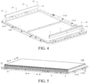
FIG. 4 is an exploded view of a tray assembly according to an embodiment of the present disclosure; -
FIG. 5 is a schematic diagram of a power battery pack according to an embodiment of the present disclosure; -
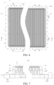
FIG. 6 is another schematic diagram of the power battery pack shown inFIG. 5 ; -
FIG. 7 is a cross-sectional view taken along line C-C inFIG. 6 ; -
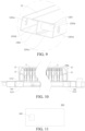
FIG. 8 is a schematic diagram of connection of an expansion beam shown inFIG. 7 ; -
FIG. 9 is a schematic diagram of the expansion beam shown inFIG. 8 ; -
FIG. 10 is still another schematic diagram of the power battery pack shown inFIG. 5 ; and -
FIG. 11 is a schematic diagram of a vehicle according to an embodiment of the present disclosure. - In the drawings:
-
Vehicle 200;power battery pack 100;battery 2; sealingcover 3; - tray assembly 1;
-
tray 11; accommodatingcavity 110;bottom plate 111;side frame 112;side beam 1121; first avoidinghole 1121a;bushing 1122; connectinghole 1122a; -
main body portion 1111; raisededge portion 1112; second avoidinghole 1112a; -
expansion beam 12; - carrying
beam 1201; carryingcavity 1201a; first carryingcavity 1201b; second carryingcavity 1201c; - mounting through
hole 1201d; avoiding throughhole 1201e; -
partition plate 1202;segmentation portion 1202a; connectingportion 1202b; -
support member 1203;support block 1203a; -
fastener 13; - first sealing
member 141;first portion 141a;third portion 141c; second sealingmember 142;fourth portion 142a; andfifth portion 142c. - Embodiments of the present disclosure are described in detail below, and examples of the embodiments are shown in accompanying drawings, where the same or similar elements or the elements having same or similar functions are denoted by the same or similar reference numerals throughout the description. The embodiments described below with reference to the accompanying drawings are exemplary and used only for explaining the present disclosure, and cannot be construed as a limitation to the present disclosure.
- The disclosure below provides many different embodiments or examples for implementing different structures of the present disclosure. To simplify the disclosure of the present disclosure, the following describes components and settings of specific examples. Certainly, the components and settings are merely examples, and are not intended to limit the present disclosure. In addition, reference numerals and/or letters may be repeated in different examples in the present disclosure. Such repetitions are for simplification and clarity, which do not indicate relationships between the embodiments and/or settings discussed. In addition, the present disclosure provides examples of various specific processes and materials, but a person of ordinary skill in the art may be aware of the applicability of other processes and/or the use of other materials.
- The following describes a tray assembly 1 according to the embodiments of the present disclosure with reference to the accompanying drawings.
- As shown in
FIG. 1 andFIG. 4 , the tray assembly 1 includes abottom plate 111. Thebottom plate 111 includes amain body portion 1111 and a raisededge portion 1112. Themain body portion 1111 defines anaccommodating cavity 110. Theaccommodating cavity 110 is configured to accommodate abattery 2. This facilitates ensuring stable mounting of thebattery 2, and in addition, thebottom plate 111 can protect thebattery 2. The raisededge portion 1112 is located on a peripheral side of themain body portion 1111, and the raisededge portion 1112 is arranged around themain body portion 1111. In this way, the raisededge portion 1112 can generally define an annular structure. - It should be noted that, in the description of the present disclosure, "annular" is to be understood in a broad sense, that is, not limited to "circular ring". For example, it may alternatively be "polygonal ring".
- The tray assembly 1 further includes an
expansion beam 12. The expansion beam (12) is arranged on one side of the raised edge portion (1112) in a thickness direction. The expansion beam (12) is adapted to abut with the battery (2). For example, theexpansion beam 12 may be in direct contact with thebattery 2, or another component may be arranged between theexpansion beam 12 and thebattery 2 to make theexpansion beam 12 indirectly abut against thebattery 2. This facilitates theexpansion beam 12 to withstand expansion force of thebattery 2. - It can be learned that, the
expansion beam 12 and thebottom plate 111 are separately processed members. - As shown in
FIG. 2 andFIG. 8 , the tray assembly 1 further includes afirst sealing member 141. Thefirst sealing member 141 includes afirst portion 141a. Thefirst portion 141a is arranged between theexpansion beam 12 and the raisededge portion 1112. In this way, a portion of thefirst sealing member 141 is arranged between theexpansion beam 12 and the raisededge portion 1112, or the entire first sealingmember 141 is arranged between theexpansion beam 12 and the raisededge portion 1112, to seal a gap between theexpansion beam 12 and the raisededge portion 1112, so that the tray assembly 1 has good sealing performance. Therefore, when the tray assembly 1 is used in apower battery pack 100, it is easy to meet a sealing requirement of thepower battery pack 100, to ensure that thepower battery pack 100 has good performance such as dustproof and waterproof. In addition, thefirst sealing member 141 is arranged conveniently, and has a large operating space. - According to the embodiments of the present disclosure, the tray assembly 1 provides the
first portion 141a of thefirst sealing member 141 between theexpansion beam 12 and the raisededge portion 1112, to seal the gap between the raisededge portion 1112 and theexpansion beam 12, so that the sealing performance of the tray assembly 1 is improved. In this way, it is easy to meet the sealing requirement of thepower battery pack 100. - In some embodiments, as shown in
FIG. 4 ,FIG. 7 , andFIG. 8 , the tray assembly 1 further includes aside frame 112. Theside frame 112 is located on a peripheral side of thebottom plate 111, and theside frame 112 is arranged around themain body portion 1111. Theside frame 112 includesmultiple side beams 1121 connected end to end in sequence, so that theside frame 112 defines an annular structure to facilitate theside frame 112 to stably support thebottom plate 111. Theside beam 1121 is located on the other side of the raisededge portion 1112 in the thickness direction, and theside beam 1121 is fixed to the raisededge portion 1112, so that theexpansion beam 12 and theside beam 1121 are located on different sides of the thickness of the raisededge portion 1112. - Optionally, the
side beam 1121 is a rolled steel member. Certainly, in other embodiments, theside beam 1121 may alternatively be an aluminum member. - As shown in
FIG. 8 , the raisededge portion 1112 forms a first avoidinghole 1112a. The tray assembly 1 further includes afastener 13. Thefastener 13 penetrates the first avoidinghole 1112a, and thefastener 13 fixedly connects theexpansion beam 12 to theside beam 1121, so that the first avoidinghole 1112a can avoid thefastener 13, to ensure that theexpansion beam 12 is smoothly fixed to acorresponding side beam 1121 through thefastener 13. Thefirst portion 141a is arranged around the first avoidinghole 1112a, to be specific, a portion of thefirst sealing member 141 between theexpansion beam 12 and the raisededge portion 1112 is arranged around the first avoidinghole 1112a. - In some embodiments, the
first sealing member 141 further includes a second portion, and the second portion is sealed between thefastener 13 and a peripheral wall of the first avoidinghole 1112a. Thefirst sealing member 141 ensures sealing between theexpansion beam 12 and the raisededge portion 1112, and also ensures sealing between thefastener 13 and the raisededge portion 1112, further improving the sealing performance of the tray assembly 1. - Optionally, the
first sealing member 141 is a structural adhesive. The structural adhesive has good strength, corrosion resistance, and stable performance, to ensure service life of the tray assembly 1. In addition, it is easy to implement bonding and fixing between theexpansion beam 12 and the raisededge portion 1112, to improve connection strength between theexpansion beam 12 and the raisededge portion 1112. A thickness of thefirst sealing member 141 is 11, where 0.5 mm ≤ t1 ≤ 1 mm. In this way, difficulty in controlling a processing process caused by an excessively small thickness of thefirst sealing member 141 can be avoided, and impact on a bonding effect of the structural adhesive caused by an excessively large thickness of thefirst sealing member 141 can also be avoided. For example, the thickness of thefirst sealing member 141 may be 0.5 mm, 0.7 mm, 0.8 mm, or 1 mm. Certainly, in other embodiments, thefirst sealing member 141 may alternatively be a sealing ring, for example, a rubber ring. - Optionally, when the
first sealing member 141 is a structural adhesive, the structural adhesive is in a liquid state during a process of assembling the tray assembly 1. The structural adhesive is arranged between theexpansion beam 12 and the raisededge portion 1112. Through extrusion between theexpansion beam 12 and the raisededge portion 1112, the structural adhesive easily overflows between thefastener 13 and the first avoidinghole 1112a. Therefore, when the structural adhesive cures to form thefirst sealing member 141, it is easy to seal thefirst portion 141a of thefirst sealing member 141 between theexpansion beam 12 and the raisededge portion 1112, and seal the second portion of thefirst sealing member 141 between thefastener 13 and the first avoidinghole 1112a. - In some embodiments, as shown in
FIG. 8 , theside frame 112 further includes abushing 1122. Thebushing 1122 penetrates the first avoidinghole 1112a, and thebushing 1122 is fixed to theside beam 1121. Thebushing 1122 forms a connectinghole 1122a. Thefastener 13 is fixedly fitted with the connectinghole 1122a. Thefirst sealing member 141 further includes athird portion 141c. Thethird portion 141c is sealed between thebushing 1122 and a peripheral wall of the first avoidinghole 1112a, to implement sealing between thebushing 1122 and the raisededge portion 1112, further improving the sealing performance of the tray assembly 1. In this case, thebushing 1122 may penetrate the first avoidinghole 1112a. - In some embodiments, as shown in
FIG. 8 , the tray assembly 1 further includes asecond sealing member 142. Thesecond sealing member 142 includes afourth portion 142a. Thefourth portion 142a is arranged between theside beam 1121 and the raisededge portion 1112. In this way, a portion of thesecond sealing member 142 is arranged between theside beam 1121 and the raisededge portion 1112, or the entire second sealingmember 142 is arranged between theside beam 1121 and the raisededge portion 1112, to seal a gap between theside beam 1121 and the raisededge portion 1112, further improving the sealing performance of the tray assembly 1. This helps ensure that thepower battery pack 100 has good performance such as dustproof and waterproof. - In some embodiments, as shown in
FIG. 2 to FIG. 4 andFIG. 8 , thefourth portion 142a is arranged around thefastener 13. To be specific, a portion of thesecond sealing member 142 between theside beam 1121 and the raisededge portion 1112 is arranged around thefastener 13, so that one side of thefastener 13 adjacent to theaccommodating cavity 110 and one side away from theaccommodating cavity 110 either are respectively arranged with one portion of thesecond sealing member 142. In this way, the portion of thesecond sealing member 142 located on the side of thefastener 13 adjacent to theaccommodating cavity 110 is sealed between theside beam 1121 and theexpansion beam 12, and the portion of thesecond sealing member 142 located on the side of thefastener 13 away from theaccommodating cavity 110 is also sealed between theside beam 1121 and theexpansion beam 12, facilitating double sealing at thefastener 13, to improve the sealing performance of the tray assembly 1. - Optionally, the
fastener 13 is a bolt. - Optionally, when the
second sealing member 142 is a structural adhesive, the structural adhesive is in a liquid state during a process of assembling the tray assembly 1. The structural adhesive is extruded when thefastener 13 fixedly connects theexpansion beam 12 to theside beam 1121. After the structural adhesive cures, it is easy to make thesecond sealing member 142 to be an integral member, to improve setting reliability of thesecond sealing member 142. - In some embodiments, as shown in
FIG. 8 , theside frame 112 further includes thebushing 1122. Theside beam 1121 forms a second avoidinghole 1121a. Thebushing 1122 is fixed to theside beam 1121, and at least a portion of thebushing 1122 is located on one side of the second avoidinghole 1121a facing away from the raisededge portion 1112. Thebushing 1122 forms a connectinghole 1122a. Thefastener 13 penetrates the second avoidinghole 1121a and penetrates the connectinghole 1122a, and thefastener 13 is fixedly fitted with the connectinghole 1122a, so that thefastener 13 is fixedly connected to thebushing 1122, and theexpansion beam 12 is fixed to acorresponding side beam 1121. - In this way, by arranging the
bushing 1122 on theside beam 1121 and allowing thefastener 13 to fixedly connect theexpansion beam 12 to thebushing 1122, fixed connection between theexpansion beam 12 and theside beam 1121 is implemented. Therefore, there is no need to separately process the connectinghole 1122a on theside beam 1121. This helps simplify a structure of theside beam 1121, and facilitates arrangement of the connectinghole 1122a. In addition, at least a portion of thebushing 1122 is located on one side of the second avoidinghole 1121a facing away from the raisededge portion 1112. This helps increase a length of thefastener 13 extending out of theexpansion beam 12, to improve connection strength between theside beam 1121 and theexpansion beam 12 to some extent. - In some embodiments, as shown in
FIG. 8 , one end of thebushing 1122 protrudes from one side of the raisededge portion 1112 facing theexpansion beam 12, and the one end of thebushing 1122 abuts against theexpansion beam 12. In this way, the one end of thebushing 1122 abuts against theexpansion beam 12 through the first avoidinghole 1112a and the second avoidinghole 1121a, so that thebushing 1122 tightly abuts against theexpansion beam 12 under an action of thefastener 13. This helps further improve the connection strength between theside beam 1121 and theexpansion beam 12. - In some embodiments, as shown in
FIG. 8 , thebushing 1122 and a peripheral wall of the second avoidinghole 1121a are welded and fixed. Thesecond sealing member 142 covers a welding seam at the second avoidinghole 1121a. In this way, thesecond sealing member 142 ensures sealing between theside beam 1121 and the raisededge portion 1112, and also ensures sealing between thebushing 1112 and theside beam 1121, further improving the sealing performance of the tray assembly 1. - Optionally, the
second sealing member 142 is a structural adhesive. The structural adhesive has good strength, corrosion resistance, and stable performance, to ensure service life of the tray assembly 1. In addition, it is easy to implement bonding and fixing between theside beam 1121 and the raisededge portion 1112, to improve connection strength between theside beam 1121 and the raisededge portion 1112. A thickness of thesecond sealing member 142 is t2, where 0.5 mm ≤ t2 ≤ 1 mm. In this way, difficulty in controlling a processing process caused by an excessively small thickness of thesecond sealing member 142 can be avoided, and impact on a bonding effect of the structural adhesive caused by an excessively large thickness of thesecond sealing member 142 can also be avoided. For example, the thickness of thesecond sealing member 142 may be 0.5 mm, 0.7 mm, 0.8 mm, or 1 mm. - In some embodiments, as shown in
FIG. 8 , thefirst sealing member 141 includes thethird portion 141c, and thethird portion 141c is sealed between thebushing 1122 and the peripheral wall of the first avoidinghole 1112a; and/or thesecond sealing member 142 includes afifth portion 142c, and thefifth portion 142c is sealed between thebushing 1122 and the peripheral wall of the first avoidinghole 1112a. The following schemes are included: 1. Thefirst sealing member 141 includes thethird portion 141c, and thethird portion 141c is sealed between thebushing 1122 and the peripheral wall of the first avoiding hole 1112a. 2. Thesecond sealing member 142 includes thefifth portion 142c, and thefifth portion 142c is sealed between thebushing 1122 and the peripheral wall of the first avoiding hole 1112a. 3. Thefirst sealing member 141 includes thethird portion 141c, thesecond sealing member 142 includes thefifth portion 142c, and either of thethird portion 141c and thefifth portion 142c is sealed between thebushing 1122 and the peripheral wall of the first avoidinghole 1112a. It can be learned that thefirst sealing member 141 and/or thesecond sealing member 142 further ensure/ensures the sealing between thebushing 1122 and the raisededge portion 1112, further improving the sealing performance of the tray assembly 1. - Optionally, when either of the
first sealing member 141 and thesecond sealing member 142 is sealed between thebushing 1122 and the peripheral wall of the first avoidinghole 1112a, thefirst sealing member 141 and thesecond sealing member 142 may form an integral member, to further improve the sealing performance of the tray assembly 1. Certainly, when a portion of thefirst sealing member 141 or a portion of thesecond sealing member 142 is sealed between thebushing 1122 and the peripheral wall of the first avoidinghole 1112a, thefirst sealing member 141 and thesecond sealing member 142 may also form an integral member. - Optionally, a reserved gap p is provided between the
bushing 1122 and the peripheral wall of the first avoidinghole 1112a, where 0.5 mm ≤ p ≤ 1 mm, to ensure that during the process of assembling the tray assembly 1, thefirst sealing member 141 and/or thesecond sealing member 142 overflow/overflows between thebushing 1122 and the peripheral wall of the first avoidinghole 1112a, to implement sealing between thebushing 1122 and the peripheral wall of the first avoidinghole 1112a. - In some embodiments, as shown in
FIG. 8 , a region of thebushing 1122 that abuts against theexpansion beam 12 is an annular region. A radial distance between an outer circumferential edge and an inner circumferential edge of the annular region is greater than or equal to 1 mm, to ensure an effective abutment between thebushing 1122 and theexpansion beam 12. - It should be noted that, in the description of the present disclosure, "annular" is to be understood in a broad sense, that is, not limited to "circular ring". For example, it may alternatively be "polygonal ring". The "annular region" may then refer to a circular annular region, a polygonal ring region, or the like. In the example of
FIG. 8 , the annular region of thebushing 1122 that abuts against theexpansion beam 12 is a circular annular region. A radial distance between an outer circumferential edge and an inner circumferential edge of the circular annular region is y, where y is greater than or equal to 1 mm. - In some embodiments, either of the
first sealing member 141 and thesecond sealing member 142 is a structural adhesive. The structural adhesive has good strength, corrosion resistance, and stable performance, to ensure service life of the tray assembly 1. A thickness of the structural adhesive is t, where 0.5 mm ≤ t ≤ 1 mm. In this way, difficulty in controlling a processing process caused by an excessively small thickness of the structural adhesive can be avoided, and impact on a bonding effect of the structural adhesive caused by an excessively large thickness of the structural adhesive can also be avoided. For example, the thickness t of the structural adhesive may be 0.5 mm, 0.7 mm, 0.8 mm, or 1 mm. - In some embodiments, the
bottom plate 111 is an insulating material member. In this case, thebottom plate 111 has good electrical insulation. Even if cooling liquid of thepower battery pack 100 leaks or the like, a risk of high-voltage arcing between thebottom plate 111 and thebattery 2 can be avoided, ensuring normal use of thepower battery pack 100. - Optionally, the
bottom plate 111 is a composite material member. It is easy to ensure structural strength of thebottom plate 111 while ensuring electrical insulation of thebottom plate 111, so that thebottom plate 111 stably carries thebattery 2. - In some embodiments, as shown in
FIG. 2, FIG. 3 ,FIG. 8 , andFIG. 9 , theexpansion beam 12 includes acarrying beam 1201 and apartition plate 1202. Thecarrying beam 1201 defines a carryingcavity 1201a. Thepartition plate 1202 is arranged in the carryingcavity 1201a to separate the carryingcavity 1201a into a first carryingcavity 1201b and a second carryingcavity 1201c. The first carryingcavity 1201b is located on one side of the second carryingcavity 1201c facing away from the raisededge portion 1112. It can be learned that when theexpansion beam 12 is in use, thepartition plate 1202 can act to transmit expansion force, to ensure a carrying capacity of theexpansion beam 12. - For example, in the example of
FIG. 8 , thefirst sealing member 141 is arranged at least between the carryingbeam 1201 and the raisededge portion 1112. - In some embodiments, as shown in
FIG. 3 andFIG. 7 , thepartition plate 1202 is arranged horizontally. A height of the first carryingcavity 1201b is equal to a height of the second carryingcavity 1201c. For example, in an up-down direction, thepartition plate 1202 is located substantially in a middle of the carryingcavity 1201a. When thebattery 2 expands, a middle position of thebattery 2 deforms the most in the up-down direction. In this case, an arrangement position of thepartition plate 1202 can better match deformation distribution of thebattery 2, to ensure that theexpansion beam 12 stably withstands the expansion force of thebattery 2. - For example, a surface of the
expansion beam 12 facing thebattery 2 is subjected to the expansion force of thebattery 2. On the surface of theexpansion beam 12, the closer to the middle position, the greater the force. By setting the height of the first carryingcavity 1201b equal to the height of the second carryingcavity 1201c, it is easy to ensure that thepartition plate 1202 stably transmits the expansion force. - In some embodiments, as shown in
FIG. 3 andFIG. 7 , in a cross section of theexpansion beam 12, thecarrying beam 1201 and thepartition plate 1202 define an "8"-shaped structure. In this case, a shape of a cross section of thecarrying beam 1201 is a square structure, and two side surfaces of width of thecarrying beam 1201 may be formed substantially into a plane. At least one of the two side surfaces may be arranged toward thebattery 2 to form a carrying surface, then the carrying surface is a plane, so that the force on theexpansion beam 12 is uniform. This helps avoid stress concentration of theexpansion beam 12 due to uneven force, reduces a risk of bending of theexpansion beam 12, and effectively ensures structural safety of the tray assembly 1. The cross section of theexpansion beam 12 is perpendicular to a length direction of theexpansion beam 12. - It may be understood that, during a process of mounting and using the
expansion beam 12, if theexpansion beam 12 interferes with another structure such as a cooling pipe, an avoiding portion may be provided on thecarrying beam 1201, to ensure smooth mounting of theexpansion beam 12 after ensuring structural strength of thecarrying beam 1201. - In some embodiments, as shown in
FIG. 3 andFIG. 7 , thecarrying beam 1201 and thepartition plate 1202 form an integral bent member, and a quantity of bending times is small. This simplifies a bending process and reduces processing costs. - For example, in the example of
FIG. 9 , for afront expansion beam 12 and amiddle expansion beam 12, thecarrying beam 1201 and thepartition plate 1202 need to be bent 7 times in the bending process, which is a simple and convenient process. - In some embodiments, as shown in
FIG. 2 and FIG. 3 , thepartition plate 1202 has asegmentation portion 1202a and a connectingportion 1202b. Thesegmentation portion 1202a is located between the first carryingcavity 1201b and the second carryingcavity 1201c. At least one of two opposite ends of thesegmentation portion 1202a is provided with the connectingportion 1202b. The connectingportion 1202b is superimposed with a cavity wall of the carryingcavity 1201a, and the connectingportion 1202b is fixedly connected to the cavity wall of the carryingcavity 1201a. A length of the connectingportion 1202b in a normal direction of thesegmentation portion 1202a is x, where 6 mm ≤ x ≤ 12 mm. In this way, by properly setting the length of the connectingportion 1202b, a connection area between the connectingportion 1202b and the cavity wall of the carryingcavity 1201a can be ensured, so that connection strength between the connectingportion 1202b and the cavity wall of the carryingcavity 1201a is ensured, to ensure a stable arrangement of thepartition plate 1202. - When the two opposite ends of the
segmentation portion 1202a are respectively arranged with connectingportions 1202b, lengths of the two connectingportions 1202b in the normal direction of thesegmentation portion 1202a may be equal or not equal. - It may be understood that, when the
carrying beam 1201 and thepartition plate 1202 form the integral bent member, the length of the connectingportion 1202b is in a range of 6 mm to 12 mm, to ensure bending convenience of thepartition plate 1202, which helps reduce difficulty of processing. In this case, a steel plate corresponding to theexpansion beam 12 has an overlapping portion at the connectingportion 1202b only. In this way, in the present disclosure, theexpansion beam 12 has a small amount of material and low costs. - Optionally, the connecting
portion 1202b and the cavity wall of the carryingcavity 1201a are welded and fixed, to ensure a sufficient welding region between the connectingportion 1202b and the cavity wall of the carryingcavity 1201a. Therefore, welding strength between the connectingportion 1202b and the cavity wall of the carryingcavity 1201a is ensured, improving a structural stability of the carryingcavity 1201a. - In some embodiments, as shown in
FIG. 8 , the tray assembly 1 further includes thefastener 13. Theexpansion beam 12 further includes asupport member 1203. Thesupport member 1203 is arranged in the second carryingcavity 1201c, and thesupport member 1203 supports thepartition plate 1202 and one cavity wall of the second carryingcavity 1201c away from thepartition plate 1202, so that thesupport member 1203 can perform a good support function on the second carryingcavity 1201c. This effectively ensures a structural stability of the second carryingcavity 1201c during a process of mounting theexpansion beam 12, using theexpansion beam 12, or the like, to avoid large deformation of the second carryingcavity 1201c, ensuring reliable use of theexpansion beam 12. Thefastener 13 penetrates thepartition plate 1202 and the second carryingcavity 1201c, and thefastener 13 extends out of the second carryingcavity 1201c to fix theexpansion beam 12 to theside beam 1121. Because thesupport member 1203 is arranged in the second carryingcavity 1201c, thesupport member 1203 can carry fastening force of thefastener 13, to avoid large deformation of thepartition plate 1202 easily caused by excessive fastening force, effectively ensuring the carrying capacity of theexpansion beam 12. - It can be learned that, in the present disclosure, arranging the
support member 1203 is helpful to reduce an arrangement requirement of thefastener 13. To be specific, when thefastener 13 is arranged, there is no need to consider a situation that the fastening force causes the large deformation of thepartition plate 1202. This facilitates arrangement of thefastener 13. - For example, in the example of
FIG. 9 , one cavity wall of the first carryingcavity 1201b facing away from the second carryingcavity 1201c forms an avoiding throughhole 1201e. Taking a plane perpendicular to an axial direction of the avoiding throughhole 1201e as a projection surface, an orthographic projection of a hole wall of the avoiding throughhole 1201e on the projection surface is located outside an outer contour of an orthographic projection of thefastener 13 on the projection surface, so that thefastener 13 can penetrate thepartition plate 1202 and the second carryingcavity 1201c through the avoiding throughhole 1201e. Thefastener 13 is a bolt. Thepartition plate 1202 forms a mating through hole. Thefastener 13 penetrates the mating through hole, and one end of thefastener 13 abuts against one side of thepartition plate 1202 facing away from the second carryingcavity 1201c. The other end of thefastener 13 is located outside the second carryingcavity 1201c, and the other end of thefastener 13 is fixedly connected to theside beam 1121. - In some embodiments, as shown in
FIG. 3 andFIG. 8 , thefastener 13 penetrates thesupport member 1203, that is, thesupport member 1203 forms a through hole. Thefastener 13 penetrates the through hole, and thefastener 13 extends out of the through hole to be fixedly connected to theside beam 1121. In this case, an edge portion of the through hole can stably carry the fastening force, so that either of thesupport member 1203 and thefastener 13 is evenly forced. This helps further avoid the large deformation of thepartition plate 1202. - Certainly, the present disclosure is not limited thereto. In other embodiments, the
support member 1203 includesmultiple support blocks 1203a. Themultiple support blocks 1203a are arranged spaced away along a second direction. Thefastener 13 is arranged between twoadjacent support blocks 1203a, so that the twoadjacent support blocks 1203a can carry the fastening force of thefastener 13. - Optionally, when the through hole is a circular hole, a diameter of the through hole is greater than or equal to an outer diameter of the
fastener 13. - In some embodiments, the
support member 1203 includesmultiple support blocks 1203a. Themultiple support blocks 1203a are arranged spaced away along a length direction of thecarrying beam 1201. Eachfastener 13 penetrates acorresponding support block 1203a. In this case,multiple fasteners 13 are arranged spaced away along the second direction, to ensure mounting and fixing of theentire expansion beam 12 while ensure that theentire partition plate 1202 does not undergo the large deformation. - It may be understood that a quantity of
support blocks 1203a may be greater than or equal to a quantity offasteners 13. Optionally, the quantity ofsupport blocks 1203a is n, where 4 ≤ n ≤ 8, but is not limited thereto. - In some embodiments, an area of a cross section of the
support member 1203 is s1, and an area of a cross section of the second carryingcavity 1201c is s2, where 50% ≤ s1/s2 ≤ 60%. Either of the cross section of thesupport member 1203 and the cross section of the second carryingcavity 1201c is perpendicular to the length direction of thecarrying beam 1201. In this way, a relative size of the area of the cross section of thesupport member 1203 and the area of the cross section of the second carryingcavity 1201c is proper. This facilitates a smooth arrangement of thesupport block 1203a in the second carryingcavity 1201c, and in addition, ensures a good carrying capacity of thesupport member 1203. - Optionally, s1/s2 may be 0.5, 0.52, 0.53, 0.55, 0.58, 0.6, or the like.
- In some embodiments, as shown in
FIG. 8 andFIG. 9 , one cavity wall of the second carryingcavity 1201c away from the first carryingcavity 1201b forms a mounting throughhole 1201d, and asupport member 1203 is arranged in the second carryingcavity 1201c. One end of thesupport member 1203 abuts against thepartition plate 1202. The other end of thesupport member 1203 is fitted with the mounting throughhole 1201d, and the other end of thesupport member 1203 is fixedly connected (for example, welded and fixed) to the cavity wall of the second carryingcavity 1201c away from thepartition plate 1201, to ensure that thesupport member 1203 effectively supports the second carryingcavity 1201c. This avoids the large deformation of the second carryingcavity 1201c, and in addition, avoids a misalignment of thesupport member 1203 relative to the second carryingcavity 1201c, ensuring a stable arrangement of thesupport member 1203. In this case, thefirst sealing member 141 may be arranged between the carryingbeam 1201 and the raisededge portion 1112, and between thesupport member 1203 and the raisededge portion 1112. - Optionally, taking a plane perpendicular to an axial direction of the mounting through
hole 1201d as a projection surface, an orthographic projection of a hole wall of the mounting throughhole 1201d on the projection surface is located outside an outer contour of an orthographic projection of thesupport member 1203 on the projection surface, so that thesupport member 1203 is adapted to be arranged in the second carryingcavity 1201c through the mounting throughhole 1201d. That is, the mounting throughhole 1201d can allow thesupport member 1203 to pass through, to facilitate mounting of thesupport member 1203. Certainly, the arrangement of thesupport member 1203 is not limited thereto. In other embodiments, thesupport member 1203 may alternatively be arranged inside the second carryingcavity 1201c through one end of the second carryingcavity 1201c in the second direction. At this case, two ends of thesupport member 1203 in a first direction may respectively abut against corresponding cavity walls of the second carryingcavity 1201c, and thesupport member 1203 can also effectively support the second carryingcavity 1201c. - In some embodiments, as shown in
FIG. 8 , theside frame 112 includes thebushing 1122. Thebushing 1122 is fixedly connected to theexpansion beam 12 and thefastener 13 separately, and one end of thebushing 1122 adjacent to theexpansion beam 12 abuts against thesupport member 1203. Thebushing 1122 tightly abuts against thesupport member 1203 under an action of thefastener 13. This helps further improve the connection strength between theside beam 1121 and theexpansion beam 12. - Optionally, the
bushing 1122 and theside beam 1121 are welded and fixed. - Optionally, a region of the
bushing 1122 that abuts against thesupport member 1203 is an annular region. A radial distance between an outer circumferential edge and an inner circumferential edge of the annular region is greater than or equal to 1 mm, to ensure an effective abutment between thebushing 1122 and thesupport member 1203. - Optionally, a wall thickness of the
bushing 1122 is equal to a wall thickness of thesupport member 1203. - According to embodiments of a second aspect of the present disclosure, as shown in
FIG. 10 , apower battery pack 100 includes abattery 2, a sealingcover 3, and the tray assembly 1 according to the embodiments of the first aspect of the present disclosure. The sealingcover 3 covers an open side of theaccommodating cavity 110, and the sealingcover 3 together with the tray assembly 1 defines a mountingspace 100a. Thebattery 2 is provided in the mountingspace 100a. - According to the embodiments of the present disclosure, the
power battery pack 100 uses the foregoing tray assembly 1, to meet a sealing requirement of thepower battery pack 100. - In some embodiments, as shown in
FIG. 1, FIG. 3 ,FIG. 5 , andFIG. 7 ,multiple batteries 2 exist, and themultiple batteries 2 are arranged in a first direction (for example, a direction AA' inFIG. 5 ). Each of thebatteries 2 extends along a second direction (for example, a direction DD' inFIG. 5 ), where the second direction is perpendicular to the first direction. A quantity ofexpansion beams 12 is two, and the twoexpansion beams 12 are respectively arranged on two sides of themultiple batteries 2 in the first direction. To be specific, oneexpansion beam 12 is arranged on one side of themultiple batteries 2 in the first direction, and theother expansion beam 12 is arranged on the other side of themultiple batteries 2 in the first direction. A direction of expansion force of thebattery 2 is substantially parallel to the first direction. Either of the expansion beams 12 extends along the second direction, so that either of the expansion beams 12 withstands the expansion force of theentire battery 2. - In this way, by arranging the expansion beams 12 respectively on two sides in an arrangement direction of the
multiple batteries 2, a small quantity ofexpansion beams 12 is used to withstand the expansion force of thebattery 2, ensuring safe use of thepower battery pack 100. - According to embodiments of a third aspect of the present disclosure, as shown in
FIG. 11 , avehicle 200 includes thepower battery pack 100 according to the embodiments of the second aspect of the present disclosure. - According to the embodiments of the present disclosure, the
vehicle 200 uses the foregoingpower battery pack 100, to ensure safe use of the vehicle. - Other configurations and operations of the
vehicle 200 according to the embodiments of the present disclosure are known to a person of ordinary skill in the art and will not be described in detail herein. - In the description of the present disclosure, it should be understood that orientation or position relationships indicated by the terms such as "center", "longitudinal", "transverse", "length", "width", "thickness", "on", "below", "front", "back", "left", "right", "vertical", "horizontal", "top", "bottom", "inside", "outside", "clockwise", "anticlockwise", "axial direction", "radial direction", and "circumferential direction" are based on orientation or position relationships shown in the accompanying drawings, and are used only for ease and brevity of illustration and description, rather than indicating or implying that the mentioned apparatus or component needs to have a particular orientation or needs to be constructed and operated in a particular orientation. Therefore, such terms should not be construed as limiting of the present disclosure. In addition, a feature defined to be "first" or "second" may explicitly or implicitly include one or more features. In the description of the present disclosure, unless otherwise stated, "a plurality of' means two or more than two.
- In the description of the present disclosure, it should be noted that, unless otherwise explicitly specified or defined, the terms such as "mount", "connect", and "connection" should be understood in a broad sense. For example, the connection may be a fixed connection, a detachable connection, or an integral connection; the connection may be a mechanical connection or an electrical connection; or the connection may be a direct connection, an indirect connection through an intermediate medium, or internal communication between two components. A person of ordinary skill in the art may understand specific meanings of the foregoing terms in the present disclosure according to specific situations.
- In the descriptions of this specification, descriptions of a reference term such as "an embodiment", "some embodiments", "an exemplary embodiment", "an example", "a specific example", or "some examples" means that a specific feature, structure, material, or characteristic that is described with reference to the embodiment or the example is included in at least one embodiment or example of the present disclosure. In this specification, schematic descriptions of the foregoing terms do not necessarily refer to the same embodiment or example. In addition, the specific feature, the structure, the material, or the characteristic that is described may be combined in a proper manner in any one or more of the embodiments or examples.
- Although the embodiments of the present disclosure have been shown and described, a person of ordinary skill in the art may understand that various changes, modifications, replacements, and variations may be made to the embodiments without departing from the principles and spirit of the present disclosure, and the scope of the present disclosure is as defined by the appended claims and their equivalents.
Claims (22)
- A tray assembly (1), comprising:a bottom plate (111), the bottom plate (111) comprising a main body portion (1111) and a raised edge portion (1112), the main body portion (1111) defining an accommodating cavity (110), the accommodating cavity (110) being configured to accommodate a battery (2), and the raised edge portion (1112) being located on a peripheral side of the main body portion (1111) and arranged around the main body portion (1111);an expansion beam (12), the expansion beam (12) being arranged on one side of the raised edge portion (1112) in a thickness direction, and the expansion beam (12) being adapted to abut with the battery (2); anda first sealing member (141), the first sealing member (141) comprising a first portion (141a), and the first portion (141a) being arranged between the expansion beam (12) and the raised edge portion (1112).
- The tray assembly (1) according to claim 1, further comprising:a side frame (112), the side frame (112) being located on a peripheral side of the bottom plate (111) and arranged around the main body portion (1111), the side frame (112) comprising a plurality of side beams (1121) connected end to end in sequence, the side beam (1121) being located on the other side of the raised edge portion (1112) in the thickness direction and fixed to the raised edge portion (1112), and the raised edge portion (1112) forming a first avoiding hole (1112a); anda fastener (13), the fastener (13) penetrating the first avoiding hole (1112a) and fixedly connecting the expansion beam (12) to a corresponding side beam (1121), and the first portion (141a) being arranged around the first avoiding hole (1112a).
- The tray assembly (1) according to claim 2, wherein the first sealing member (141) further comprises a second portion, and the second portion is sealed between the fastener (13) and a peripheral wall of the first avoiding hole (1112a).
- The tray assembly (1) according to claim 2, wherein the side frame (112) further comprises a bushing (1122), the bushing (1122) penetrating the first avoiding hole (1112a) and being fixed to the side beam (1121), the bushing (1122) forms a connecting hole (1122a), the fastener (13) being fixedly fitted with the connecting hole (1122a); and
the first sealing member (141) further comprises a third portion (141c), and the third portion (141c) being sealed between the bushing (1122) and a peripheral wall of the first avoiding hole (1112a). - The tray assembly (1) according to any one of claims 1 to 4, further comprising:
a second sealing member (142), the second sealing member (142) comprising a fourth portion (142a), and the fourth portion (142a) being arranged between the side beam (1121) and the raised edge portion (1112). - The tray assembly (1) according to claim 5, wherein the fourth portion (142a) is arranged around the fastener (13).
- The tray assembly (1) according to claim 5 or 6, wherein the side frame (112) further comprises the bushing (1122), the side beam (1121) forms a second avoiding hole (1121a), the bushing (1122) being fixed to the side beam (1121) and at least a portion of the bushing (1122) is located on one side of the second avoiding hole (1121a) facing away from the raised edge portion, the bushing (1122) forms a connecting hole (1122a), and the fastener (13) penetrating the second avoiding hole (1121a) and being fixedly fitted with the connecting hole (1122a).
- The tray assembly (1) according to any one of claims 1 to 7, wherein one end of the bushing (1122) protrudes from one side of the raised edge portion (1112) facing the expansion beam (12) and abuts against the expansion beam (12).
- The tray assembly (1) according to any one of claims 1 to 8, wherein the bushing (1122) and a peripheral wall of the second avoiding hole (1121a) are welded and fixed, and the second sealing member (142) covers a welding seam at the second avoiding hole (1121a).
- The tray assembly (1) according to any one of claims 1 to 9, whereinthe first sealing member (141) comprises the third portion (141c), and the third portion being sealed between the bushing (1122) and the peripheral wall of the first avoiding hole (1112a); and/orthe second sealing member (142) comprises a fifth portion (142c), and the fifth portion (142c) being sealed between the bushing (1122) and the peripheral wall of the first avoiding hole (1112a).
- The tray assembly (1) according to any one of claims 1 to 10, wherein a region of the bushing (1122) that abuts against the expansion beam (12) is an annular region, and a radial distance between an outer circumferential edge and an inner circumferential edge of the annular region is greater than or equal to 1 mm.
- The tray assembly (1) according to any one of claims 1 to 11, wherein either of the first sealing member (141) and the second sealing member (142) is a structural adhesive, a thickness of the structural adhesive is t, and 0.5 mm ≤ t ≤ 1 mm.
- The tray assembly (1) according to any one of claims 1 to 12, wherein the bottom plate (111) is an insulating material member.
- The tray assembly (1) according to any one of claims 1 to 13, wherein the expansion beam (12) comprises a carrying beam (1201) and a partition plate (1202), the carrying beam (1201) defines a carrying cavity (1201a), the partition plate (1202) being arranged in the carrying cavity (1201a) to separate the carrying cavity (1201a) into a first carrying cavity (1201b) and a second carrying cavity (1201c), and the first carrying cavity (1201b) being located on one side of the second carrying cavity (1201c) facing away from the raised edge portion (1112).
- The tray assembly (1) according to any one of claims 1 to 14, further comprising the fastener (13), and the expansion beam (12) further comprising:
a support member (1203), the support member (1203) being arranged in the second carrying cavity (1201c), the support member (1203) supporting one cavity wall of the second carrying cavity (1201c) away from the partition plate (1202) and the partition plate (1202), and the fastener (13) penetrating the partition plate (1202) and the second carrying cavity (1201c) and extending out of the second carrying cavity (1201c) to fix the expansion beam (12) to the side beam (1121). - The tray assembly (1) according to any one of claims 1 to 15, wherein the support member (1203) comprises a plurality of support blocks (1203a), the plurality of support blocks (1203a) being arranged spaced away along a length direction of the carrying beam (1201), and each fastener (13) penetrating a corresponding support block (1203a).
- The tray assembly (1) according to any one of claims 1 to 16, wherein an area of a cross section of the support member (1203) is s1, an area of a cross section of the second carrying cavity (1201c) is s2, 50% ≤ s1/s2 ≤ 60%, and either of the cross section of the support member (1203) and the cross section of the second carrying cavity (1201c) being perpendicular to the length direction of the carrying beam (1201).
- The tray assembly (1) according to any one of claims 1 to 17, wherein one cavity wall of the second carrying cavity (1201c) away from the first carrying cavity (1201b) forms a mounting through hole (1201d), the support member (1203) being arranged in the second carrying cavity (1201c), one end of the support member (1203) abuts against the partition plate (1202), and the other end of the support member (1203) being fitted with the mounting through hole (1201d) and fixedly connected to the cavity wall of the second carrying cavity (1201c) away from the partition plate (1202).
- The tray assembly (1) according to any one of claims 1 to 18, wherein the side frame (112) comprises the bushing (1122), the bushing (1122) being fixedly connected to the expansion beam (12) and the fastener (13) separately, and one end of the bushing (1122) adjacent to the expansion beam (12) abuts against the support member (1203).
- A power battery pack (100), comprising a battery (2), a sealing cover (3), and the tray assembly (1) according to any one of claims 1 to 19, the sealing cover (3) covering an open side of the accommodating cavity (110) and together with the tray assembly (1) defining a mounting space (100a), and the battery (2) being provided in the mounting space (100a).
- The power battery pack (100) according to claim 20, wherein a plurality of batteries (2) exist, the plurality of batteries (2) being arranged in a first direction in sequence, each of the batteries (2) extends along a second direction, a quantity of expansion beams (12) is two, the two expansion beams (12) being respectively arranged on two sides of the plurality of batteries (2) in the first direction, either of the expansion beams (12) extends along the second direction, and the second direction being perpendicular to the first direction.
- A vehicle (200), comprising the power battery pack (100) according to claim 20 or 21.
Applications Claiming Priority (2)
| Application Number | Priority Date | Filing Date | Title |
|---|---|---|---|
| CN202220566246.5U CN217158428U (en) | 2022-03-14 | 2022-03-14 | Tray assembly, power battery pack and vehicle |
| PCT/CN2023/081434 WO2023174303A1 (en) | 2022-03-14 | 2023-03-14 | Tray assembly, power battery pack, and vehicle |
Publications (2)
| Publication Number | Publication Date |
|---|---|
| EP4439833A1 true EP4439833A1 (en) | 2024-10-02 |
| EP4439833A4 EP4439833A4 (en) | 2025-04-23 |
Family
ID=82696049
Family Applications (1)
| Application Number | Title | Priority Date | Filing Date |
|---|---|---|---|
| EP23769805.5A Pending EP4439833A4 (en) | 2022-03-14 | 2023-03-14 | TRAY ASSEMBLY, BATTERY PACK AND VEHICLE |
Country Status (6)
| Country | Link |
|---|---|
| US (1) | US20240347843A1 (en) |
| EP (1) | EP4439833A4 (en) |
| JP (1) | JP7780021B2 (en) |
| KR (1) | KR20240112340A (en) |
| CN (1) | CN217158428U (en) |
| WO (1) | WO2023174303A1 (en) |
Families Citing this family (9)
| Publication number | Priority date | Publication date | Assignee | Title |
|---|---|---|---|---|
| CN217158428U (en) * | 2022-03-14 | 2022-08-09 | 比亚迪股份有限公司 | Tray assembly, power battery pack and vehicle |
| CN115275474B (en) * | 2022-09-19 | 2023-01-24 | 蜂巢能源科技股份有限公司 | Battery box structure and battery package |
| CN119789998A (en) * | 2023-04-24 | 2025-04-08 | 宁德时代(上海)智能科技有限公司 | Side beam assembly, chassis and vehicle |
| CN120016051A (en) * | 2023-11-16 | 2025-05-16 | 宁德时代新能源科技股份有限公司 | Battery boxes, batteries and electrical devices |
| CN118099638B (en) * | 2024-03-01 | 2025-12-09 | 惠州亿纬锂能股份有限公司 | Battery box beam, battery box body and battery module |
| WO2025179666A1 (en) * | 2024-03-01 | 2025-09-04 | 惠州亿纬锂能股份有限公司 | Battery case beam, battery case, and battery module |
| EP4611138A1 (en) * | 2024-03-01 | 2025-09-03 | Eve Energy Co., Ltd. | Battery box beam, battery box and battery module |
| CN221632742U (en) * | 2024-06-13 | 2024-08-30 | 宁德时代新能源科技股份有限公司 | Expansion beam, box assembly, battery and electricity utilization device |
| CN120749307B (en) * | 2025-08-27 | 2026-01-09 | 宁德时代新能源科技股份有限公司 | Battery device and electricity utilization device |
Family Cites Families (12)
| Publication number | Priority date | Publication date | Assignee | Title |
|---|---|---|---|---|
| CN201329795Y (en) | 2008-12-12 | 2009-10-21 | 比亚迪股份有限公司 | Sealing structure for power battery of vehicle |
| CN201329796Y (en) * | 2008-12-12 | 2009-10-21 | 比亚迪股份有限公司 | Installation structure for power battery of vehicle |
| CN202268406U (en) * | 2011-08-24 | 2012-06-06 | 中信国安盟固利动力科技有限公司 | Lithium ion battery composite frame and battery pack |
| US10886513B2 (en) * | 2017-05-16 | 2021-01-05 | Shape Corp. | Vehicle battery tray having tub-based integration |
| CN207449607U (en) | 2017-11-03 | 2018-06-05 | 北京新能源汽车股份有限公司 | Battery box and vehicle |
| CN108232073A (en) | 2017-12-29 | 2018-06-29 | 智车优行科技(上海)有限公司 | Battery for electric automobile babinet and its manufacturing method, electric vehicle |
| KR102544785B1 (en) | 2018-12-18 | 2023-06-15 | 주식회사 엘지에너지솔루션 | Battery pack and vehicle comprising the battery pack |
| JP7457129B2 (en) * | 2020-03-27 | 2024-03-27 | 寧徳時代新能源科技股▲分▼有限公司 | Housing, battery group and device |
| CN213042998U (en) * | 2020-08-12 | 2021-04-23 | 恒大新能源技术(深圳)有限公司 | Battery case, battery pack and vehicle |
| CN213501812U (en) * | 2020-10-30 | 2021-06-22 | 重庆长安新能源汽车科技有限公司 | A battery tray and vehicle |
| CN214505663U (en) * | 2020-12-30 | 2021-10-26 | 蜂巢能源科技有限公司 | Cooling device for battery pack and battery pack |
| CN217158428U (en) * | 2022-03-14 | 2022-08-09 | 比亚迪股份有限公司 | Tray assembly, power battery pack and vehicle |
-
2022
- 2022-03-14 CN CN202220566246.5U patent/CN217158428U/en active Active
-
2023
- 2023-03-14 KR KR1020247021438A patent/KR20240112340A/en active Pending
- 2023-03-14 JP JP2024537507A patent/JP7780021B2/en active Active
- 2023-03-14 EP EP23769805.5A patent/EP4439833A4/en active Pending
- 2023-03-14 WO PCT/CN2023/081434 patent/WO2023174303A1/en not_active Ceased
-
2024
- 2024-06-26 US US18/755,263 patent/US20240347843A1/en active Pending
Also Published As
| Publication number | Publication date |
|---|---|
| JP7780021B2 (en) | 2025-12-03 |
| JP2025503475A (en) | 2025-02-04 |
| EP4439833A4 (en) | 2025-04-23 |
| KR20240112340A (en) | 2024-07-18 |
| WO2023174303A1 (en) | 2023-09-21 |
| CN217158428U (en) | 2022-08-09 |
| US20240347843A1 (en) | 2024-10-17 |
Similar Documents
| Publication | Publication Date | Title |
|---|---|---|
| EP4439833A1 (en) | Tray assembly, power battery pack, and vehicle | |
| JP5552109B2 (en) | In-vehicle battery tray and in-vehicle battery frame | |
| US11031649B2 (en) | Housing for a vehicle battery, and method for manufacturing a housing of said type | |
| EP3088225B1 (en) | Vehicle battery mounting structure | |
| CN109461852B (en) | Battery carrier for electric vehicle | |
| EP2705554B1 (en) | Battery cover assembly and battery having the same | |
| CN217788612U (en) | Expansion beam assembly for power battery pack, power battery pack and vehicle | |
| CN106876621A (en) | Rechargeable battery module | |
| EP4037081A1 (en) | Battery compartment, battery compartment assembly and electric scooter | |
| CN114206711A (en) | Vehicle floor for an energy storage floor assembly of a motor vehicle | |
| CN107128265A (en) | Battery support structure | |
| KR20240110045A (en) | Edge beams for battery trays, battery trays, battery packs, and vehicles | |
| US20240356119A1 (en) | Cylindrical Battery, Electric Apparatus and Manufacturing Method for Cylindrical Battery | |
| CN111668411B (en) | Battery tray, power battery package and vehicle | |
| KR102440895B1 (en) | Hybrid type applied battery case | |
| CN210897345U (en) | Battery pack lower shell and battery pack | |
| CN115249864B (en) | Battery tray, battery pack and vehicle | |
| CN213768241U (en) | Battery pack for vehicle and vehicle | |
| EP4557498A1 (en) | Battery | |
| CN218577883U (en) | Vehicle body of vehicle and vehicle | |
| CN217300741U (en) | Adopt trapezoidal recess to bend reinforcing curb plate rigidity type oil tank | |
| CN211530886U (en) | Supporting structure for water-cooled motor and water-cooled motor | |
| CN221262593U (en) | Battery pack lower shell, battery pack shell and battery pack | |
| CN223778435U (en) | Charging port assembly and vehicle | |
| CN223200149U (en) | Rear floor beam frame assembly and vehicle |
Legal Events
| Date | Code | Title | Description |
|---|---|---|---|
| STAA | Information on the status of an ep patent application or granted ep patent |
Free format text: STATUS: THE INTERNATIONAL PUBLICATION HAS BEEN MADE |
|
| PUAI | Public reference made under article 153(3) epc to a published international application that has entered the european phase |
Free format text: ORIGINAL CODE: 0009012 |
|
| STAA | Information on the status of an ep patent application or granted ep patent |
Free format text: STATUS: REQUEST FOR EXAMINATION WAS MADE |
|
| 17P | Request for examination filed |
Effective date: 20240628 |
|
| AK | Designated contracting states |
Kind code of ref document: A1 Designated state(s): AL AT BE BG CH CY CZ DE DK EE ES FI FR GB GR HR HU IE IS IT LI LT LU LV MC ME MK MT NL NO PL PT RO RS SE SI SK SM TR |
|
| REG | Reference to a national code |
Ref country code: DE Ref legal event code: R079 Free format text: PREVIOUS MAIN CLASS: H01M0050244000 Ipc: H01M0050242000 |
|
| A4 | Supplementary search report drawn up and despatched |
Effective date: 20250320 |
|
| RIC1 | Information provided on ipc code assigned before grant |
Ipc: H01M 50/249 20210101ALI20250314BHEP Ipc: H01M 50/233 20210101ALI20250314BHEP Ipc: H01M 50/244 20210101ALI20250314BHEP Ipc: H01M 50/242 20210101AFI20250314BHEP |
|
| DAV | Request for validation of the european patent (deleted) | ||
| DAX | Request for extension of the european patent (deleted) | ||
| GRAP | Despatch of communication of intention to grant a patent |
Free format text: ORIGINAL CODE: EPIDOSNIGR1 |
|
| STAA | Information on the status of an ep patent application or granted ep patent |
Free format text: STATUS: GRANT OF PATENT IS INTENDED |
|
| INTG | Intention to grant announced |
Effective date: 20260128 |