EP4439803A1 - Battery module, and battery pack and automobile comprising same - Google Patents
Battery module, and battery pack and automobile comprising same Download PDFInfo
- Publication number
- EP4439803A1 EP4439803A1 EP23775336.3A EP23775336A EP4439803A1 EP 4439803 A1 EP4439803 A1 EP 4439803A1 EP 23775336 A EP23775336 A EP 23775336A EP 4439803 A1 EP4439803 A1 EP 4439803A1
- Authority
- EP
- European Patent Office
- Prior art keywords
- supply
- cooling water
- connection passage
- battery module
- passage
- Prior art date
- Legal status (The legal status is an assumption and is not a legal conclusion. Google has not performed a legal analysis and makes no representation as to the accuracy of the status listed.)
- Granted
Links
Images





Classifications
-
- H—ELECTRICITY
- H01—ELECTRIC ELEMENTS
- H01M—PROCESSES OR MEANS, e.g. BATTERIES, FOR THE DIRECT CONVERSION OF CHEMICAL ENERGY INTO ELECTRICAL ENERGY
- H01M10/00—Secondary cells; Manufacture thereof
- H01M10/60—Heating or cooling; Temperature control
- H01M10/61—Types of temperature control
- H01M10/613—Cooling or keeping cold
-
- H—ELECTRICITY
- H01—ELECTRIC ELEMENTS
- H01M—PROCESSES OR MEANS, e.g. BATTERIES, FOR THE DIRECT CONVERSION OF CHEMICAL ENERGY INTO ELECTRICAL ENERGY
- H01M10/00—Secondary cells; Manufacture thereof
- H01M10/60—Heating or cooling; Temperature control
- H01M10/62—Heating or cooling; Temperature control specially adapted for specific applications
- H01M10/625—Vehicles
-
- H—ELECTRICITY
- H01—ELECTRIC ELEMENTS
- H01M—PROCESSES OR MEANS, e.g. BATTERIES, FOR THE DIRECT CONVERSION OF CHEMICAL ENERGY INTO ELECTRICAL ENERGY
- H01M10/00—Secondary cells; Manufacture thereof
- H01M10/60—Heating or cooling; Temperature control
- H01M10/65—Means for temperature control structurally associated with the cells
- H01M10/655—Solid structures for heat exchange or heat conduction
- H01M10/6556—Solid parts with flow channel passages or pipes for heat exchange
-
- H—ELECTRICITY
- H01—ELECTRIC ELEMENTS
- H01M—PROCESSES OR MEANS, e.g. BATTERIES, FOR THE DIRECT CONVERSION OF CHEMICAL ENERGY INTO ELECTRICAL ENERGY
- H01M10/00—Secondary cells; Manufacture thereof
- H01M10/60—Heating or cooling; Temperature control
- H01M10/65—Means for temperature control structurally associated with the cells
- H01M10/656—Means for temperature control structurally associated with the cells characterised by the type of heat-exchange fluid
- H01M10/6567—Liquids
- H01M10/6568—Liquids characterised by flow circuits, e.g. loops, located externally to the cells or cell casings
-
- H—ELECTRICITY
- H01—ELECTRIC ELEMENTS
- H01M—PROCESSES OR MEANS, e.g. BATTERIES, FOR THE DIRECT CONVERSION OF CHEMICAL ENERGY INTO ELECTRICAL ENERGY
- H01M50/00—Constructional details or processes of manufacture of the non-active parts of electrochemical cells other than fuel cells, e.g. hybrid cells
- H01M50/20—Mountings; Secondary casings or frames; Racks, modules or packs; Suspension devices; Shock absorbers; Transport or carrying devices; Holders
- H01M50/204—Racks, modules or packs for multiple batteries or multiple cells
-
- H—ELECTRICITY
- H01—ELECTRIC ELEMENTS
- H01M—PROCESSES OR MEANS, e.g. BATTERIES, FOR THE DIRECT CONVERSION OF CHEMICAL ENERGY INTO ELECTRICAL ENERGY
- H01M50/00—Constructional details or processes of manufacture of the non-active parts of electrochemical cells other than fuel cells, e.g. hybrid cells
- H01M50/20—Mountings; Secondary casings or frames; Racks, modules or packs; Suspension devices; Shock absorbers; Transport or carrying devices; Holders
- H01M50/233—Mountings; Secondary casings or frames; Racks, modules or packs; Suspension devices; Shock absorbers; Transport or carrying devices; Holders characterised by physical properties of casings or racks, e.g. dimensions
-
- H—ELECTRICITY
- H01—ELECTRIC ELEMENTS
- H01M—PROCESSES OR MEANS, e.g. BATTERIES, FOR THE DIRECT CONVERSION OF CHEMICAL ENERGY INTO ELECTRICAL ENERGY
- H01M50/00—Constructional details or processes of manufacture of the non-active parts of electrochemical cells other than fuel cells, e.g. hybrid cells
- H01M50/20—Mountings; Secondary casings or frames; Racks, modules or packs; Suspension devices; Shock absorbers; Transport or carrying devices; Holders
- H01M50/249—Mountings; Secondary casings or frames; Racks, modules or packs; Suspension devices; Shock absorbers; Transport or carrying devices; Holders specially adapted for aircraft or vehicles, e.g. cars or trains
-
- H—ELECTRICITY
- H01—ELECTRIC ELEMENTS
- H01M—PROCESSES OR MEANS, e.g. BATTERIES, FOR THE DIRECT CONVERSION OF CHEMICAL ENERGY INTO ELECTRICAL ENERGY
- H01M50/00—Constructional details or processes of manufacture of the non-active parts of electrochemical cells other than fuel cells, e.g. hybrid cells
- H01M50/20—Mountings; Secondary casings or frames; Racks, modules or packs; Suspension devices; Shock absorbers; Transport or carrying devices; Holders
- H01M50/271—Lids or covers for the racks or secondary casings
-
- H—ELECTRICITY
- H01—ELECTRIC ELEMENTS
- H01M—PROCESSES OR MEANS, e.g. BATTERIES, FOR THE DIRECT CONVERSION OF CHEMICAL ENERGY INTO ELECTRICAL ENERGY
- H01M2220/00—Batteries for particular applications
- H01M2220/20—Batteries in motive systems, e.g. vehicle, ship, plane
-
- Y—GENERAL TAGGING OF NEW TECHNOLOGICAL DEVELOPMENTS; GENERAL TAGGING OF CROSS-SECTIONAL TECHNOLOGIES SPANNING OVER SEVERAL SECTIONS OF THE IPC; TECHNICAL SUBJECTS COVERED BY FORMER USPC CROSS-REFERENCE ART COLLECTIONS [XRACs] AND DIGESTS
- Y02—TECHNOLOGIES OR APPLICATIONS FOR MITIGATION OR ADAPTATION AGAINST CLIMATE CHANGE
- Y02E—REDUCTION OF GREENHOUSE GAS [GHG] EMISSIONS, RELATED TO ENERGY GENERATION, TRANSMISSION OR DISTRIBUTION
- Y02E60/00—Enabling technologies; Technologies with a potential or indirect contribution to GHG emissions mitigation
- Y02E60/10—Energy storage using batteries
Definitions
- the present invention relates to a battery module capable of minimizing a temperature deviation in an entire battery cell during cooling of the battery cell and improving cooling efficiency, a battery pack including the same, and vehicle.
- secondary batteries are commonly applied to portable devices as well as electric vehicles (EVs) or hybrid electric vehicles (HEVs) driven by an electric driving source.
- EVs electric vehicles
- HEVs hybrid electric vehicles
- These secondary batteries are attracting attention as a new energy source for improving eco-friendliness and energy efficiency in that the secondary batteries are capable of drastically reducing the use of fossil fuels and do not generate any by-products.
- the plurality of secondary batteries are connected to each other to constitute a battery module.
- the battery module needs a cooling system to prevent overheating. That is, as a capacity of the battery module increases, an amount of generated heat increases, and thus, a water-cooling type cooling system is required instead of an air-cooling type cooling system.
- the water-cooling type cooling system according to the related art has a problem in that it is difficult to uniformly cool the entire battery module. That is, the water-cooling type cooling system according to the related art has a problem in that a temperature deviation in entire battery module occurs, and as a result, cooling efficiency is deteriorated.
- An object of the present invention is to provide a battery module capable of minimizing a temperature deviation in an entire battery cell during cooling of the battery cell and improving cooling efficiency, a battery pack including the same, and vehicle.
- a battery module of the present invention includes a case assembly configured to accommodate and cool a battery cell, wherein the case assembly includes: a top cooling member provided with a top plate configured to cover a top surface of the battery cell, a first heatsink configured to cool the top surface of the battery cell while cooling water passes therethrough, a first supply port configured to supply the cooling water to the first heatsink, and a first discharge port configured to discharge the cooling water passing through the first heatsink; a bottom cooling member provided with a bottom plate configured to cover a bottom surface of the battery cell, a second heatsink configured to cool the bottom surface of the battery cell while the cooling water passes therethrough, a second supply port configured to supply the cooling water to the second heatsink, and a second discharge port configured to discharge the cooling water passing through the second heatsink; and a connector member provided with a front plate configured to cover one surface of the battery cell in a full-length direction, a supply part configured to supply the cooling water to the first and second supply port, and a collection part configured to collect the cooling
- the supply part and the collection part may be provided in the front plate.
- the supply part may include: a first connection passage provided in the central cover to pass vertically and having upper end lower ends, to which the first supply port and the second supply port are coupled respectively, to supply the cooling water to the first and second supply ports; and a supply passage configured to pass from the outside of the central cover to the first connection passage and supply the cooling water to the first connection passage.
- the supply passage may be configured to pass from a side portion of the central cover, which protrudes to the outside of the side cover, to the first connection passage.
- the collection part comprises: a second connection passage provided in the central cover to vertically pass and having upper and lower ends, to which the first discharge port and the second discharge port are coupled, respectively, so that the cooling water discharged from the first and second discharge ports passes therethrough; and a collection passage configured to pass from a side portion of the central cover to the second connection passage and collect the cooling water passing through the second connection passage.
- the collection passage may be configured to pass from a side portion of the central cover, which protrudes to the outside of the side cover, to the second connection passage.
- a coupling hole into which each of the first and second supply ports is fitted may be defined in each of both ends of the first connection passage, and a coupling piece coupled to the first connection passage may be disposed on each of the first supply port and the second supply port.
- a coupling hole into which each of the first and second discharge ports is fitted may be defined in each of both ends of the second connection passage, and a coupling piece coupled to the second connection passage may be disposed on each of the first discharge port and the second discharge port.
- a sealing ring may be provided between a coupling hole of the first connection passage and the first supply port or between the coupling hole of the first connection passage and the second supply port.
- a sealing ring may be provided between a coupling hole of the second connection passage and the first discharge port or between the coupling hole of the second connection passage and the second discharge port.
- the battery module may further include a pair of side plates configured to cover both sides of the battery cell in the full-width direction, respectively.
- the pair of side plate and the bottom plate may be integrated with each other.
- the battery module may further include a rear plate configured to cover the other side of the battery cell in the full-length direction.
- a vehicle of the present invention includes: a battery pack; and a cooling water supply device configured to supply cooling water to a supply line of the battery pack or collect the cooling water passing through the collection line.
- the battery module of the present invention may include the case assembly for cooling the battery cell using the cooling water, and the case assembly may include the top cooling member, the bottom cooling member, and the connector member. Due to this features, the upper and lower portions of the battery cell may be effectively cooled, and in particular, the entire battery cell may be uniformly cooled, and as a result, the cooling efficiency may be improved by minimizing the temperature deviation of the entire battery cell.
- a battery module 10 includes a battery cell 100 and a case assembly that cools the battery cell 100 using cooling water 200.
- the case assembly 200 includes a top cooling member 210 that cools an upper portion of the battery cell 100 using cooling water, a bottom cooling member 220 that cools a lower portion of the battery cell 100 using the cooling water, and a connector member 230 that supplies or collects the cooling water to/from the top cooling member 210 and the bottom cooling member 220.
- the top cooling member 210 and the bottom cooling member 220 have a symmetrical structure with respect to the battery cell 100, and thus manufacturing efficiency may be improved.
- the top cooling member 210 includes a top plate 211, a first heatsink 212, a first supply port 213 and a first discharge port 214.
- the first heatsink 212 is disposed on a top surface of the top plate 211 to cool the top surface of the battery cell 100 while the cooling water passes therethrough. That is, referring to FIG. 5 , the first heatsink 212 cools the entire top surface of the battery cell 100 while providing a cooling water passages through which the cooling water passes in the entire surface. An inlet of the cooling water passage is connected to the first supply port 213, and an outlet is connected to the first discharge port 214.
- the first supply port 213 is configured to supply the cooling water to the first heatsink 212 and also is coupled to one side of a bottom surface of the upper extension part 211a and is connected to the inlet of the cooling water passage provided in the first heatsink 212 to supply the cooling water to the cooling water passage of the first heatsink 212.
- the first discharge port 214 is configured to discharge the cooling water passing through the first heatsink 212 and also is coupled to the other side of the bottom surface of the upper extension part 211a and is connected to the outlet of the cooling water passage provided in the first heatsink 212 to discharge the cooling water passing through the first heatsink 212.
- the cooling water may be supplied into the first heatsink 212 through the first supply port 213, and the cooling water supplied into the first heatsink 212 may cool the entire top surface of the battery cell 100 while passing through the cooling water passage.
- the cooling water passage passes through the entire top surface of the battery cell 100, the entire top surface of the battery cell 100 may be uniformly cooled, and as a result, a temperature deviation of the entire top surface of the battery cell 100 may be minimized.
- the cooling water that has passed through the first heatsink 212 is discharged to the first discharge port 214.
- the first supply port 213 and the first discharge port 214 may be detachably coupled to the upper extension part 211a. Thus, when the first supply port 213 and the first discharge port 214 are damaged, the first supply port 213 and the first discharge port 214 may be easily replaced.
- the bottom cooling member 220 includes a bottom plate 221, a second heatsink 222, a second supply port 223 and a second discharge port 224.
- the bottom plate 221 is made of a metal material and has an area covering the entire bottom surface of the battery cell 100.
- the bottom plate 221 is provided with a lower extension part 221a extending out of the battery cell 100, and the second supply port 223 and the second discharge port 224 are coupled to the lower extension part 221a. That is, the lower extension part 221a may separate the second supply port 223 and the second discharge port 224 from the battery cell 100 to prevent the second supply port 223 and the second discharge port 224 from being in contact with each other, and as a result, prevent the battery cell 100 from being damaged.
- the second heatsink 222 is disposed on a bottom surface of the top plate 211 to cool the bottom surface of the battery cell 100 while the cooling water passes therethrough.
- the second heatsink 222 has the same cooling water passage as the first heatsink 212. That is, referring to FIG. 5 , the second heatsink 222 cools the entire bottom surface of the battery cell 100 while providing the cooling water passages through which the cooling water passes in the entire surface.
- the inlet of the cooling water passage is connected to the second supply port 223, and the outlet is connected to the second discharge port 224.
- the second supply port 223 is configured to supply the cooling water to the second heatsink 222 and also is coupled to the top surface of the lower extension part 221a and is connected to the inlet of the cooling water passage provided in the second heatsink 222 to supply the cooling water to the cooling water passage of the second heatsink 222.
- the second discharge port 224 is configured to discharge the cooling water passing through the second heatsink 222 and also is coupled to the top surface of the lower extension part 221a and is connected to the outlet of the cooling water passage provided in the second heatsink 222 to discharge the cooling water passing through the second heatsink 222.
- the cooling water may be supplied into the second heatsink 222 through the second supply port 223, and the cooling water supplied into the second heatsink 222 may cool the entire bottom surface of the battery cell 100 while passing through the cooling water passage.
- the cooling water passage passes through the entire bottom surface of the battery cell 100, the entire bottom surface of the battery cell 100 may be uniformly cooled.
- the cooling water that has passed through the second heatsink 222 is discharged through the second discharge port 224.
- the present invention has a structure in which the top cooling member 210 and the bottom cooling member 220 are symmetrical to each other, and thus, the top and bottom surfaces of the battery cell 100 may be uniformly cooled, particularly a temperature deviation of the top and bottom surfaces of the battery cell 100 may be minimized to improve cooling efficiency.
- the connector member 230 includes a front plate 231, a supply part 232 and a collection part 233.
- the front plate 231 is made of a metal material and covers one surface of the battery cell 100 in a full-length direction (a front surface of the battery cell when viewed in FIG. 2 ). That is, the front plate 231 is provided between a pair of side covers 231a, which cover both sides of one surface of the battery cell 100 in the full-length direction, respectively, and a central cover which is provided between the pair of side covers 231a and in which the supply part 232 and the collection part 233 are provided.
- the front plate 231 may prevent the battery module 10 from increasing in volume because the supply part 232 and the collection part 233 are provided therein, and may protect the supply part 232 and the collection part 233 against an external impact.
- the pair of side covers 231a and the central cover 231b may be integrally provided, as illustrated in FIG. 2 , the central cover 231b may further protrude outward from the side covers 231a (front side of the battery cell when viewed in FIG. 2 ).
- a clearance that is, an empty space
- the tolerance serves to block a temperature changes of the battery cell, which is caused by the cooling water passing through the supply part and the collection part.
- the supply part 232 is configured to supply the cooling water to the first and second supply ports. That is, the supply part 232 includes a first connection passage 232a and a supply passage 232b.
- the first connection passage 232a is provided to pass vertically through the central cover 231b when viewed in FIG. 1 , and the first supply port 213 and the second supply port 223 are coupled to the first supply port 213 and the second supply port 223 to supply the cooling water to the first supply port 213 and the second supply port 223, respectively.
- the supply passage 232b passes from the outside of the central cover 231b to the first connection passage 232a to supply the cooling water to the first connection passage 232a.
- the inlet of the supply passage 232b may be provided to pass from a side portion (left portion of the central cover 231b when viewed in FIG. 6 ) of the central cover 231b, which protrude to the outside of the side cover 231a, to the first connection passage 232a. That is, since the central cover protrudes more outward than the side cover, the supply passage may be connected to the first connection passage through a side surface of the central cover.
- usability of a space between a front surface of the side cover 231a and a left surface of the central cover 231b may increase, and as a result, an increase in volume of the battery module 10 in the full-length direction may be prevented.
- the collection part 233 is configured to collect the cooling water discharged from the first and second discharge ports. That is, the collection part 233 includes a second connection passage 233a and a collection passage 233b.
- the second connection passage 233a is provided to pass vertically through the central cover 231b, and the first discharge port 214 and the second discharge port 224 are coupled to upper and lower ends of the second connection passage 233a, respectively, so that the cooling water passes through the first and second discharge ports.
- the collection passage 233b passes from the side portion of the central cover 231b (a right side of the central cover 231b when viewed in FIG. 6 ) to the second connection passage 233a to collect the cooling water passing through the second connection passage 233a.
- the collection passage 233b passes from the side portion of the central cover 231b protruding to the outside of the side cover 231a to the second connection passage 233a. That is, since the central cover protrudes more outward than the side cover, the collection passage may be connected to the second connection passage through the side surface of the central cover. Thus, usability of a side space of the central cover 231b may be improved, and as a result, the increase in volume of the battery module 10 in the full-length direction may be minimized.
- a coupling hole 232c into which each of the first supply port 213 and the second supply port 223 is fitted may be defined in each of both ends of the first connection passage 232a, and each of the first and second supply ports 213 and 223 and the coupling hole 232c may have a diameter greater than that of the first connection passage 232a.
- the first and second supply ports 213 and 223 may be supported by the first connection passage 232a to improve the coupling therebetween.
- a coupling piece 213a that is fitted into the first connection passage 232a is disposed on each of the first supply port 213 and the second supply port 223. That is, the coupling piece 213a has a cylindrical shape. Thus, coupling force and sealing force between the first connection passage 232a and the first and second supply ports 213 and 223 may increase.
- a sealing ring 234 may be provided between the coupling hole 232c of the first connection passage 232a and the first supply port 213 or between the coupling hole 232c of the first connection passage 232a and the second supply port 223. That is, sealing force between the coupling hole 232c of the first connection passage 232a and the first supply port 213 or between the coupling hole 232c of the first connection passage 232a and the second supply port 223 may be significantly improved. Two or more sealing rings 234 may be provided.
- a coupling hole 233c into which each of the first and second discharge ports is fitted is defined in each of both ends of the second connection passage 233a, and each of the first and second discharge ports and the coupling hole 233c has a diameter greater than that of the second connection passage 233a.
- a coupling piece 214a coupled to the second connection passage 233a is disposed on each of the first discharge port 214 and the second discharge port 224. That is, the coupling piece 214a has a cylindrical shape. Thus, coupling force and sealing force between the second connection passage 233a and the first and second discharge ports may increase.
- a sealing ring 234 may be provided between the coupling hole of the second connection passage 233a and the first discharge port 214 or between the coupling hole of the second connection passage 233a and the second discharge port 224. That is, sealing force between the coupling hole of the second connection passage 233a and the first supply port 214 or between the coupling hole of the second connection passage 233a and the second supply port 224 may be significantly improved.
- the case assembly 200 may further include a pair of side plates 240 respectively covering both sides in the full-width direction of the battery cell 100.
- the side plate 240 may be integrated with the bottom plate 221 to improve efficiency when assembling the battery module.
- the case assembly 200 may further include a rear plate 250 covering the other side of the battery cell 100 in the full-width direction.
- a rear plate 250 covering the other side of the battery cell 100 in the full-width direction.
- the case assembly 200 may accommodate and cool the entire battery cell 100 while the top plate 211, the bottom plate 221, the pair of side plates 240, and the rear plate 250 are assembled.
- the battery module 10 according to the first embodiment of the present invention having the above configuration may uniformly cool the upper and lower portions of the battery cell 100, and in particular, minimize the temperature deviation of the entire battery cell 100, and as a result, the cooling efficiency may be improved.
- a battery cell 100 is disposed on a top surface of a bottom plate 221 with which a side plate 240 is integrated.
- a second supply port 223 and a second discharge port 224 which are coupled to a lower extension part 221a of the bottom plate 221, are spaced apart from the battery cell 100.
- the connector member 230 is disposed on one surface of the battery cell 100 in a full-width direction, but a lower end of a first connection passage 232a and a second supply port 223, which are provided in the supply part 232, are coupled to each other, and a lower end of the second connection passage 233a and a second discharge port 224, which are provided in a collection part 233, are coupled to each other.
- the second supply port 223 may be coupled to a coupling hole provided in a lower end of the first connection passage 232a, and a coupling piece 223a of the second supply port 223 may be coupled to the first connection passage 232a to improve coupling force.
- the second discharge passage may be coupled to a lower end of the second connection passage 233a, and a coupling piece 224a of the second discharge port 224 may be coupled to the second connection passage 233a to improve coupling force.
- a sealing ring 234 is provided between the first connection passage 232a and the second supply port 223 and between the second connection passage 233a and the second discharge port 224 to improve sealing force.
- a rear plate 250 is coupled to the other surface of the battery cell 100 in a full-length direction.
- a top cooling member 210 is placed on an upper portion of the battery cell 100.
- a first supply port 213 and a first discharge port 214 which are coupled to an upper extension part 211a of a top plate 211, are spaced apart from the battery cell 100.
- the first supply port 213 and an upper end of the first connection passage 232a are coupled to each other, and the first discharge port 214 and an upper end of the second connection passage 233a are coupled to each other.
- the first supply port 213 may be coupled to a coupling hole provided in an upper end of the first connection passage 232a, and a coupling piece 213a of the first supply port 213 may be coupled to the first connection passage 232a to improve coupling force.
- first discharge passage may be coupled to an upper end of the second connection passage 233a, and a coupling piece 214a of the first discharge port 214 may be coupled to the second connection passage 233a to improve coupling force.
- a sealing ring 234 is provided between the first connection passage 232a and the first supply port 213 and between the second connection passage 233a and the first discharge port 214 to improve sealing force.
- a finished battery module 10 as illustrated in FIG. 11 may be obtained.
- a cooling water supply line is connected to a supply passage 232b of a supply part 232, and a cooling water collection line is connected to a collection passage 233b of a collection part 233.
- the cooling water is supplied to the battery module 10 through a supply line. Then, the cooling water supplied through the supply line sequentially passes through the supply passage 232b, the first connection passage 232a, and the first and second supply ports 213 of the supply part 232 and 223, and then is introduced into first and second heatsinks 212 and 222 to cool the entire battery cell 100.
- the cooling water passing through the first and second heatsinks 212 and 222 is introduced into the second connection passage 233a through the first and second discharge ports 214 and 224, and the cooling water introduced into the second connection passage 233a is collected into the collection line through the collection passage 233b. Next, the cooling water is supplied to the supply line again after performing a cooling process.
- a battery pack according to a second embodiment of the present invention includes a battery module 10; and a pack case 20 in which at least one or more battery modules 10 are accommodated.
- the battery module 10 has the same configuration as the battery module 10 described in the first embodiment, and therefore, redundant description will be omitted.
- the pack case 20 includes a supply line 21 that supplies cooling water to a supply passage 232b of the battery module 10 and a collection line through which the cooling water collected from the collection passage 233b of the battery module 10 passes. (22). That is, the supply line is connected to the supply passage 232b of a supply part 232 provided in the battery module 10, and the collection line is connected to the collection passage 233b of a collection part 233 provided in the battery module 10.
- the battery pack 1 according to the second embodiment of the present invention may improve cooling efficiency of the battery module 10 as a whole, and in particular, may minimize a cooling deviation.
- a vehicle includes a battery pack 1; and a cooling water supply device 2 configured to supply cooling water to a supply line of the battery pack 1 or collect the cooling water passing through a collection line.
- the battery pack has the same configuration as the battery pack described in the second embodiment, and therefore, redundant description is omitted.
- the cooling water supply device may be a radiator that cools an engine using the cooling water. That is, the radiator supplies a portion of the cooling water that cools the engine to the battery pack or collects the cooling water passing through the battery pack.
- the vehicle according to the third embodiment of the present invention may improve its performance by including the battery pack with high cooling efficiency.
- the case assembly may function as the battery module or the battery pack, and in particular, the case assembly may separately include a housing, which accommodates the battery cells, at the outside thereof.
Landscapes
- Chemical & Material Sciences (AREA)
- Chemical Kinetics & Catalysis (AREA)
- Electrochemistry (AREA)
- General Chemical & Material Sciences (AREA)
- Engineering & Computer Science (AREA)
- Manufacturing & Machinery (AREA)
- Aviation & Aerospace Engineering (AREA)
- Secondary Cells (AREA)
- Battery Mounting, Suspending (AREA)
Abstract
Description
- The present application claims the benefit of the priority of
Korean Patent Application Nos. 10-2022-0036333, filed on March 23, 2022 10-2023-0037478, filed on March 22, 2023 - The present invention relates to a battery module capable of minimizing a temperature deviation in an entire battery cell during cooling of the battery cell and improving cooling efficiency, a battery pack including the same, and vehicle.
- In general, secondary batteries are commonly applied to portable devices as well as electric vehicles (EVs) or hybrid electric vehicles (HEVs) driven by an electric driving source. These secondary batteries are attracting attention as a new energy source for improving eco-friendliness and energy efficiency in that the secondary batteries are capable of drastically reducing the use of fossil fuels and do not generate any by-products.
- The plurality of secondary batteries are connected to each other to constitute a battery module. Here, the battery module needs a cooling system to prevent overheating. That is, as a capacity of the battery module increases, an amount of generated heat increases, and thus, a water-cooling type cooling system is required instead of an air-cooling type cooling system.
- However, the water-cooling type cooling system according to the related art has a problem in that it is difficult to uniformly cool the entire battery module. That is, the water-cooling type cooling system according to the related art has a problem in that a temperature deviation in entire battery module occurs, and as a result, cooling efficiency is deteriorated.
- An object of the present invention is to provide a battery module capable of minimizing a temperature deviation in an entire battery cell during cooling of the battery cell and improving cooling efficiency, a battery pack including the same, and vehicle.
- A battery module of the present invention includes a case assembly configured to accommodate and cool a battery cell, wherein the case assembly includes: a top cooling member provided with a top plate configured to cover a top surface of the battery cell, a first heatsink configured to cool the top surface of the battery cell while cooling water passes therethrough, a first supply port configured to supply the cooling water to the first heatsink, and a first discharge port configured to discharge the cooling water passing through the first heatsink; a bottom cooling member provided with a bottom plate configured to cover a bottom surface of the battery cell, a second heatsink configured to cool the bottom surface of the battery cell while the cooling water passes therethrough, a second supply port configured to supply the cooling water to the second heatsink, and a second discharge port configured to discharge the cooling water passing through the second heatsink; and a connector member provided with a front plate configured to cover one surface of the battery cell in a full-length direction, a supply part configured to supply the cooling water to the first and second supply port, and a collection part configured to collect the cooling water discharged from the first and second discharge ports, wherein the front plate includes: a pair of side covers configured to cover both sides of the battery cell in the full-length direction, respectively; and a central cover which is provided between the pair of side covers and in which the supply part and the collection part are provided, wherein the central cover further protrudes outward from each of the side covers.
- The supply part and the collection part may be provided in the front plate.
- The supply part may include: a first connection passage provided in the central cover to pass vertically and having upper end lower ends, to which the first supply port and the second supply port are coupled respectively, to supply the cooling water to the first and second supply ports; and a supply passage configured to pass from the outside of the central cover to the first connection passage and supply the cooling water to the first connection passage.
- The supply passage may be configured to pass from a side portion of the central cover, which protrudes to the outside of the side cover, to the first connection passage.
- The collection part comprises: a second connection passage provided in the central cover to vertically pass and having upper and lower ends, to which the first discharge port and the second discharge port are coupled, respectively, so that the cooling water discharged from the first and second discharge ports passes therethrough; and a collection passage configured to pass from a side portion of the central cover to the second connection passage and collect the cooling water passing through the second connection passage.
- The collection passage may be configured to pass from a side portion of the central cover, which protrudes to the outside of the side cover, to the second connection passage.
- A coupling hole into which each of the first and second supply ports is fitted may be defined in each of both ends of the first connection passage, and a coupling piece coupled to the first connection passage may be disposed on each of the first supply port and the second supply port.
- A coupling hole into which each of the first and second discharge ports is fitted may be defined in each of both ends of the second connection passage, and a coupling piece coupled to the second connection passage may be disposed on each of the first discharge port and the second discharge port.
- A sealing ring may be provided between a coupling hole of the first connection passage and the first supply port or between the coupling hole of the first connection passage and the second supply port.
- A sealing ring may be provided between a coupling hole of the second connection passage and the first discharge port or between the coupling hole of the second connection passage and the second discharge port.
- The battery module may further include a pair of side plates configured to cover both sides of the battery cell in the full-width direction, respectively.
- The pair of side plate and the bottom plate may be integrated with each other.
- The battery module may further include a rear plate configured to cover the other side of the battery cell in the full-length direction.
- A battery pack of the present invention includes: a battery module; and a pack case in which at least one or more battery modules are accommodated, wherein the pack case includes: a supply line configured to supply cooling water to a supply passage of the battery module; and a collection line through which the cooling water collected from a collection passage of the battery module passes.
- A vehicle of the present invention includes: a battery pack; and a cooling water supply device configured to supply cooling water to a supply line of the battery pack or collect the cooling water passing through the collection line.
- The battery module of the present invention may include the case assembly for cooling the battery cell using the cooling water, and the case assembly may include the top cooling member, the bottom cooling member, and the connector member. Due to this features, the upper and lower portions of the battery cell may be effectively cooled, and in particular, the entire battery cell may be uniformly cooled, and as a result, the cooling efficiency may be improved by minimizing the temperature deviation of the entire battery cell.
-
-
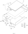
FIG. 1 is an exploded perspective view of a battery module according to a first embodiment of the present invention. -
FIG. 2 is a front view of the pouch module according to the first embodiment of the present invention. -
FIG. 3 is a plan view of the pouch module according to the first embodiment of the present invention. -
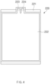
FIG. 4 is a bottom view of the battery module according to the first embodiment of the present invention. -
FIG. 5 is a cross-sectional view of first and second heatsinks according to the first embodiment of the present invention. -
FIG. 6 is a cross-sectional view of a connector member according to the first embodiment of the present invention. -
FIG. 7 is a partial enlarged view ofFIG. 6 . -
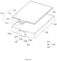
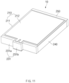
FIGS. 8 to 11 are views illustrating a method for assembling a battery module according to the first embodiment of the present invention. -
FIG. 12 is a schematic front view of a battery pack according to a second embodiment of the present invention. -
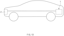
FIG. 13 is a side view of a vehicle according to a third embodiment of the present invention. - Hereinafter, embodiments of the present invention will be described in detail with reference to the accompanying drawings in such a manner that the technical idea of the present invention may easily be carried out by a person with ordinary skill in the art to which the invention pertains. The present invention may, however, be embodied in different forms and should not be construed as limited to the embodiments set forth herein. In the drawings, anything unnecessary for describing the present invention will be omitted for clarity, and also like reference numerals in the drawings denote like elements.
- As illustrated in
FIGS. 1 to 4 , abattery module 10 according to a first embodiment of the present invention includes abattery cell 100 and a case assembly that cools thebattery cell 100 usingcooling water 200. - The
battery cell 100 includes an electrode assembly, an electrolyte, and a case accommodating the electrode assembly and the electrolyte. The electrode assembly has a structure in which a plurality of electrodes and a plurality of separators are alternately disposed. The plurality of electrodes may be a positive electrode and a negative electrode. - The
case assembly 200 includes atop cooling member 210 that cools an upper portion of thebattery cell 100 using cooling water, abottom cooling member 220 that cools a lower portion of thebattery cell 100 using the cooling water, and aconnector member 230 that supplies or collects the cooling water to/from thetop cooling member 210 and thebottom cooling member 220. Here, thetop cooling member 210 and thebottom cooling member 220 have a symmetrical structure with respect to thebattery cell 100, and thus manufacturing efficiency may be improved. - The
top cooling member 210 includes atop plate 211, afirst heatsink 212, afirst supply port 213 and afirst discharge port 214. - The
top plate 211 is made of a metal material and has an area covering an entire top surface of thebattery cell 100. In addition, thetop plate 211 is provided with an upper extension part 211a extending out of thebattery cell 100, and thefirst supply port 213 and thefirst discharge port 214 are coupled to the upper extension part 211a. That is, the upper extension part 211a may separate thefirst supply port 213 and thefirst discharge port 214 from thebattery cell 100 to prevent thefirst supply port 213 and thefirst discharge port 214 from being in contact with each other, and as a result, prevent thebattery cell 100 from being damaged. - The
first heatsink 212 is disposed on a top surface of thetop plate 211 to cool the top surface of thebattery cell 100 while the cooling water passes therethrough. That is, referring toFIG. 5 , thefirst heatsink 212 cools the entire top surface of thebattery cell 100 while providing a cooling water passages through which the cooling water passes in the entire surface. An inlet of the cooling water passage is connected to thefirst supply port 213, and an outlet is connected to thefirst discharge port 214. - The
first supply port 213 is configured to supply the cooling water to thefirst heatsink 212 and also is coupled to one side of a bottom surface of the upper extension part 211a and is connected to the inlet of the cooling water passage provided in thefirst heatsink 212 to supply the cooling water to the cooling water passage of thefirst heatsink 212. - The
first discharge port 214 is configured to discharge the cooling water passing through thefirst heatsink 212 and also is coupled to the other side of the bottom surface of the upper extension part 211a and is connected to the outlet of the cooling water passage provided in thefirst heatsink 212 to discharge the cooling water passing through thefirst heatsink 212. - When the
top cooling member 210 having the above-described configuration is disposed on the top surface of thebattery cell 100, the cooling water may be supplied into thefirst heatsink 212 through thefirst supply port 213, and the cooling water supplied into thefirst heatsink 212 may cool the entire top surface of thebattery cell 100 while passing through the cooling water passage. Here, since the cooling water passage passes through the entire top surface of thebattery cell 100, the entire top surface of thebattery cell 100 may be uniformly cooled, and as a result, a temperature deviation of the entire top surface of thebattery cell 100 may be minimized. The cooling water that has passed through thefirst heatsink 212 is discharged to thefirst discharge port 214. - The
first supply port 213 and thefirst discharge port 214 may be detachably coupled to the upper extension part 211a. Thus, when thefirst supply port 213 and thefirst discharge port 214 are damaged, thefirst supply port 213 and thefirst discharge port 214 may be easily replaced. - The
bottom cooling member 220 includes abottom plate 221, asecond heatsink 222, asecond supply port 223 and asecond discharge port 224. - The
bottom plate 221 is made of a metal material and has an area covering the entire bottom surface of thebattery cell 100. Thebottom plate 221 is provided with a lower extension part 221a extending out of thebattery cell 100, and thesecond supply port 223 and thesecond discharge port 224 are coupled to the lower extension part 221a. That is, the lower extension part 221a may separate thesecond supply port 223 and thesecond discharge port 224 from thebattery cell 100 to prevent thesecond supply port 223 and thesecond discharge port 224 from being in contact with each other, and as a result, prevent thebattery cell 100 from being damaged. - The
second heatsink 222 is disposed on a bottom surface of thetop plate 211 to cool the bottom surface of thebattery cell 100 while the cooling water passes therethrough. Here, thesecond heatsink 222 has the same cooling water passage as thefirst heatsink 212. That is, referring toFIG. 5 , thesecond heatsink 222 cools the entire bottom surface of thebattery cell 100 while providing the cooling water passages through which the cooling water passes in the entire surface. The inlet of the cooling water passage is connected to thesecond supply port 223, and the outlet is connected to thesecond discharge port 224. - The
second supply port 223 is configured to supply the cooling water to thesecond heatsink 222 and also is coupled to the top surface of the lower extension part 221a and is connected to the inlet of the cooling water passage provided in thesecond heatsink 222 to supply the cooling water to the cooling water passage of thesecond heatsink 222. - The
second discharge port 224 is configured to discharge the cooling water passing through thesecond heatsink 222 and also is coupled to the top surface of the lower extension part 221a and is connected to the outlet of the cooling water passage provided in thesecond heatsink 222 to discharge the cooling water passing through thesecond heatsink 222. - When the
bottom cooling member 220 having the above-described configuration is disposed on the bottom surface of thebattery cell 100, the cooling water may be supplied into thesecond heatsink 222 through thesecond supply port 223, and the cooling water supplied into thesecond heatsink 222 may cool the entire bottom surface of thebattery cell 100 while passing through the cooling water passage. Here, since the cooling water passage passes through the entire bottom surface of thebattery cell 100, the entire bottom surface of thebattery cell 100 may be uniformly cooled. The cooling water that has passed through thesecond heatsink 222 is discharged through thesecond discharge port 224. - In particular, the present invention has a structure in which the
top cooling member 210 and thebottom cooling member 220 are symmetrical to each other, and thus, the top and bottom surfaces of thebattery cell 100 may be uniformly cooled, particularly a temperature deviation of the top and bottom surfaces of thebattery cell 100 may be minimized to improve cooling efficiency. - As illustrated in
FIGS. 6 and7 , theconnector member 230 includes afront plate 231, asupply part 232 and acollection part 233. - The
front plate 231 is made of a metal material and covers one surface of thebattery cell 100 in a full-length direction (a front surface of the battery cell when viewed inFIG. 2 ). That is, thefront plate 231 is provided between a pair of side covers 231a, which cover both sides of one surface of thebattery cell 100 in the full-length direction, respectively, and a central cover which is provided between the pair of side covers 231a and in which thesupply part 232 and thecollection part 233 are provided. - The
front plate 231 may prevent thebattery module 10 from increasing in volume because thesupply part 232 and thecollection part 233 are provided therein, and may protect thesupply part 232 and thecollection part 233 against an external impact. - The pair of side covers 231a and the
central cover 231b may be integrally provided, as illustrated inFIG. 2 , thecentral cover 231b may further protrude outward from the side covers 231a (front side of the battery cell when viewed inFIG. 2 ). Thus, a clearance (that is, an empty space) is provided between thecentral cover 231b and thebattery cell 100, and the clearance allows the supply port and thebattery cell 100 to be separated from being separated from each other and allows the discharge port and thebattery cell 100 to be separated from being separated from each other, thereby preventing contact therebetween. In particular, the tolerance serves to block a temperature changes of the battery cell, which is caused by the cooling water passing through the supply part and the collection part. - The
supply part 232 is configured to supply the cooling water to the first and second supply ports. That is, thesupply part 232 includes afirst connection passage 232a and asupply passage 232b. - The
first connection passage 232a is provided to pass vertically through thecentral cover 231b when viewed inFIG. 1 , and thefirst supply port 213 and thesecond supply port 223 are coupled to thefirst supply port 213 and thesecond supply port 223 to supply the cooling water to thefirst supply port 213 and thesecond supply port 223, respectively. Thesupply passage 232b passes from the outside of thecentral cover 231b to thefirst connection passage 232a to supply the cooling water to thefirst connection passage 232a. - The inlet of the
supply passage 232b may be provided to pass from a side portion (left portion of thecentral cover 231b when viewed inFIG. 6 ) of thecentral cover 231b, which protrude to the outside of theside cover 231a, to thefirst connection passage 232a. That is, since the central cover protrudes more outward than the side cover, the supply passage may be connected to the first connection passage through a side surface of the central cover. Thus, when viewed inFIG. 2 , usability of a space between a front surface of theside cover 231a and a left surface of thecentral cover 231b may increase, and as a result, an increase in volume of thebattery module 10 in the full-length direction may be prevented. - The
collection part 233 is configured to collect the cooling water discharged from the first and second discharge ports. That is, thecollection part 233 includes asecond connection passage 233a and acollection passage 233b. - When viewed in
FIG. 1 , thesecond connection passage 233a is provided to pass vertically through thecentral cover 231b, and thefirst discharge port 214 and thesecond discharge port 224 are coupled to upper and lower ends of thesecond connection passage 233a, respectively, so that the cooling water passes through the first and second discharge ports. In addition, thecollection passage 233b passes from the side portion of thecentral cover 231b (a right side of thecentral cover 231b when viewed inFIG. 6 ) to thesecond connection passage 233a to collect the cooling water passing through thesecond connection passage 233a. - The
collection passage 233b passes from the side portion of thecentral cover 231b protruding to the outside of theside cover 231a to thesecond connection passage 233a. That is, since the central cover protrudes more outward than the side cover, the collection passage may be connected to the second connection passage through the side surface of the central cover. Thus, usability of a side space of thecentral cover 231b may be improved, and as a result, the increase in volume of thebattery module 10 in the full-length direction may be minimized. - A coupling hole 232c into which each of the
first supply port 213 and thesecond supply port 223 is fitted may be defined in each of both ends of thefirst connection passage 232a, and each of the first andsecond supply ports first connection passage 232a. Thus, after each of the first andsecond supply ports second supply ports first connection passage 232a to improve the coupling therebetween. - In particular, a
coupling piece 213a that is fitted into thefirst connection passage 232a is disposed on each of thefirst supply port 213 and thesecond supply port 223. That is, thecoupling piece 213a has a cylindrical shape. Thus, coupling force and sealing force between thefirst connection passage 232a and the first andsecond supply ports - A sealing
ring 234 may be provided between the coupling hole 232c of thefirst connection passage 232a and thefirst supply port 213 or between the coupling hole 232c of thefirst connection passage 232a and thesecond supply port 223. That is, sealing force between the coupling hole 232c of thefirst connection passage 232a and thefirst supply port 213 or between the coupling hole 232c of thefirst connection passage 232a and thesecond supply port 223 may be significantly improved. Two or more sealing rings 234 may be provided. - A coupling hole 233c into which each of the first and second discharge ports is fitted is defined in each of both ends of the
second connection passage 233a, and each of the first and second discharge ports and the coupling hole 233c has a diameter greater than that of thesecond connection passage 233a. Thus, after each of the first and second discharge ports is inserted into the coupling hole 233c, the first and second discharge ports may be supported by thesecond connection passage 233a to improve coupling therebetween. - A
coupling piece 214a coupled to thesecond connection passage 233a is disposed on each of thefirst discharge port 214 and thesecond discharge port 224. That is, thecoupling piece 214a has a cylindrical shape. Thus, coupling force and sealing force between thesecond connection passage 233a and the first and second discharge ports may increase. - A sealing
ring 234 may be provided between the coupling hole of thesecond connection passage 233a and thefirst discharge port 214 or between the coupling hole of thesecond connection passage 233a and thesecond discharge port 224. That is, sealing force between the coupling hole of thesecond connection passage 233a and thefirst supply port 214 or between the coupling hole of thesecond connection passage 233a and thesecond supply port 224 may be significantly improved. - The
case assembly 200 may further include a pair ofside plates 240 respectively covering both sides in the full-width direction of thebattery cell 100. In particular, theside plate 240 may be integrated with thebottom plate 221 to improve efficiency when assembling the battery module. - The
case assembly 200 may further include arear plate 250 covering the other side of thebattery cell 100 in the full-width direction. Thus, the other side of thebattery cell 100 in the full-width direction may be stably protected. - On the other hand, the
case assembly 200 may accommodate and cool theentire battery cell 100 while thetop plate 211, thebottom plate 221, the pair ofside plates 240, and therear plate 250 are assembled. - The
battery module 10 according to the first embodiment of the present invention having the above configuration may uniformly cool the upper and lower portions of thebattery cell 100, and in particular, minimize the temperature deviation of theentire battery cell 100, and as a result, the cooling efficiency may be improved. - Hereinafter, a method of assembling and operating the
battery module 10 according to the first embodiment of the present invention will be described. - First, as illustrated in
FIG. 8 , abattery cell 100 is disposed on a top surface of abottom plate 221 with which aside plate 240 is integrated. Here, asecond supply port 223 and asecond discharge port 224, which are coupled to a lower extension part 221a of thebottom plate 221, are spaced apart from thebattery cell 100. - Next, as illustrated in
FIG. 9 , theconnector member 230 is disposed on one surface of thebattery cell 100 in a full-width direction, but a lower end of afirst connection passage 232a and asecond supply port 223, which are provided in thesupply part 232, are coupled to each other, and a lower end of thesecond connection passage 233a and asecond discharge port 224, which are provided in acollection part 233, are coupled to each other. Here, thesecond supply port 223 may be coupled to a coupling hole provided in a lower end of thefirst connection passage 232a, and acoupling piece 223a of thesecond supply port 223 may be coupled to thefirst connection passage 232a to improve coupling force. In addition, the second discharge passage may be coupled to a lower end of thesecond connection passage 233a, and acoupling piece 224a of thesecond discharge port 224 may be coupled to thesecond connection passage 233a to improve coupling force. In addition, a sealingring 234 is provided between thefirst connection passage 232a and thesecond supply port 223 and between thesecond connection passage 233a and thesecond discharge port 224 to improve sealing force. - Next, a
rear plate 250 is coupled to the other surface of thebattery cell 100 in a full-length direction. - Next, as illustrated in
FIG. 10 , atop cooling member 210 is placed on an upper portion of thebattery cell 100. Here, afirst supply port 213 and afirst discharge port 214, which are coupled to an upper extension part 211a of atop plate 211, are spaced apart from thebattery cell 100. Then, thefirst supply port 213 and an upper end of thefirst connection passage 232a are coupled to each other, and thefirst discharge port 214 and an upper end of thesecond connection passage 233a are coupled to each other. Here, thefirst supply port 213 may be coupled to a coupling hole provided in an upper end of thefirst connection passage 232a, and acoupling piece 213a of thefirst supply port 213 may be coupled to thefirst connection passage 232a to improve coupling force. In addition, the first discharge passage may be coupled to an upper end of thesecond connection passage 233a, and acoupling piece 214a of thefirst discharge port 214 may be coupled to thesecond connection passage 233a to improve coupling force. In addition, a sealingring 234 is provided between thefirst connection passage 232a and thefirst supply port 213 and between thesecond connection passage 233a and thefirst discharge port 214 to improve sealing force. - When the assembly is completed as described above, a
finished battery module 10 as illustrated inFIG. 11 may be obtained. - In the
finished battery module 10 as described above, a cooling water supply line is connected to asupply passage 232b of asupply part 232, and a cooling water collection line is connected to acollection passage 233b of acollection part 233. In addition, while charging and discharging thebattery module 10, the cooling water is supplied to thebattery module 10 through a supply line. Then, the cooling water supplied through the supply line sequentially passes through thesupply passage 232b, thefirst connection passage 232a, and the first andsecond supply ports 213 of thesupply part second heatsinks entire battery cell 100. The cooling water passing through the first andsecond heatsinks second connection passage 233a through the first andsecond discharge ports second connection passage 233a is collected into the collection line through thecollection passage 233b. Next, the cooling water is supplied to the supply line again after performing a cooling process. - Hereinafter, in describing another embodiment of the present invention, the same reference numerals are used for the same components as those of the above-described embodiment, and duplicated descriptions will be omitted.
- As illustrated in
FIG. 12 , a battery pack according to a second embodiment of the present invention includes abattery module 10; and apack case 20 in which at least one ormore battery modules 10 are accommodated. - The
battery module 10 has the same configuration as thebattery module 10 described in the first embodiment, and therefore, redundant description will be omitted. - The
pack case 20 includes asupply line 21 that supplies cooling water to asupply passage 232b of thebattery module 10 and a collection line through which the cooling water collected from thecollection passage 233b of thebattery module 10 passes. (22). That is, the supply line is connected to thesupply passage 232b of asupply part 232 provided in thebattery module 10, and the collection line is connected to thecollection passage 233b of acollection part 233 provided in thebattery module 10. - Therefore, the
battery pack 1 according to the second embodiment of the present invention may improve cooling efficiency of thebattery module 10 as a whole, and in particular, may minimize a cooling deviation. - As illustrated in
FIG. 13 , a vehicle according to a third embodiment of the present invention includes abattery pack 1; and a coolingwater supply device 2 configured to supply cooling water to a supply line of thebattery pack 1 or collect the cooling water passing through a collection line. - The battery pack has the same configuration as the battery pack described in the second embodiment, and therefore, redundant description is omitted.
- The cooling water supply device may be a radiator that cools an engine using the cooling water. That is, the radiator supplies a portion of the cooling water that cools the engine to the battery pack or collects the cooling water passing through the battery pack.
- Therefore, the vehicle according to the third embodiment of the present invention may improve its performance by including the battery pack with high cooling efficiency.
- The case assembly may function as the battery module or the battery pack, and in particular, the case assembly may separately include a housing, which accommodates the battery cells, at the outside thereof.
- Accordingly, the scope of the present invention is defined by the appended claims more than the foregoing description and the exemplary embodiments described therein. Various modifications made within the meaning of an equivalent of the claims of the invention and within the claims are to be regarded to be in the scope of the present invention.
-
- 1: Battery pack
- 2: Cooling water supply device
- 10: Battery module
- 20: Pack case
- 21: Supply line
- 22: Collection line
- 100: Battery cell
- 200: Case assembly
- 210: Top cooling member
- 211: Top plate
- 211a: Upper extension part
- 212: First heatsink
- 213: First supply port
- 213a, 214a, 223a, 224a: Coupling piece
- 214: First discharge port
- 220: Bottom cooling member
- 221: Bottom plate
- 221a: Lower extension part
- 222: Second heatsink
- 223: Second supply port
- 224: Second discharge port
- 230: Connector member
- 231: Front plate
- 231a: Side cover
- 231b: Central cover
- 232: Supply part
- 232a: First connection passage
- 232b: Supply passage
- 232c: Coupling hole
- 233: Collection part
- 233a: Second connection passage
- 233c: Coupling hole
- 233b: Collection passage
- 234: Sealing ring
- 240: Side plate
- 250: Rear plate
Claims (15)
- A battery module comprising a case assembly configured to accommodate and cool a battery cell,
wherein the case assembly comprises:a top cooling member provided with a top plate configured to cover a top surface of the battery cell, a first heatsink configured to cool the top surface of the battery cell while cooling water passes therethrough, a first supply port configured to supply the cooling water to the first heatsink, and a first discharge port configured to discharge the cooling water passing through the first heatsink;a bottom cooling member provided with a bottom plate configured to cover a bottom surface of the battery cell, a second heatsink configured to cool the bottom surface of the battery cell while the cooling water passes therethrough, a second supply port configured to supply the cooling water to the second heatsink, and a second discharge port configured to discharge the cooling water passing through the second heatsink; anda connector member provided with a front plate configured to cover one surface of the battery cell in a full-length direction, a supply part configured to supply the cooling water to the first and second supply port, and a collection part configured to collect the cooling water discharged from the first and second discharge ports,wherein the front plate comprises:a pair of side covers configured to cover both sides of the battery cell in the full-length direction, respectively; anda central cover which is provided between the pair of side covers and in which the supply part and the collection part are provided,wherein the central cover further protrudes outward from each of the side covers. - The battery module of claim 1, wherein the supply part and the collection part are provided in the front plate.
- The battery module of claim 2, wherein the supply part comprises:a first connection passage provided in the central cover to pass vertically and having upper end lower ends, to which the first supply port and the second supply port are coupled respectively, to supply the cooling water to the first and second supply ports; anda supply passage configured to pass from the outside of the central cover to the first connection passage and supply the cooling water to the first connection passage.
- The battery module of claim 3, wherein the supply passage is configured to pass from a side portion of the central cover, which protrudes to the outside of the side cover, to the first connection passage.
- The battery module of claim 2, wherein the collection part comprises:a second connection passage provided in the central cover to vertically pass and having upper and lower ends, to which the first discharge port and the second discharge port are coupled, respectively, so that the cooling water discharged from the first and second discharge ports passes therethrough; anda collection passage configured to pass from a side portion of the central cover to the second connection passage and collect the cooling water passing through the second connection passage.
- The battery module of claim 5, wherein the collection passage is configured to pass from a side portion of the central cover, which protrudes to the outside of the side cover, to the second connection passage.
- The battery module of claim 3, wherein a coupling hole into which each of the first and second supply ports is fitted is defined in each of both ends of the first connection passage, and
a coupling piece coupled to the first connection passage is disposed on each of the first supply port and the second supply port. - The battery module of claim 5, wherein a coupling hole into which each of the first and second discharge ports is fitted is defined in each of both ends of the second connection passage, and
a coupling piece coupled to the second connection passage is disposed on each of the first discharge port and the second discharge port. - The battery module of claim 7, wherein a sealing ring is provided between a coupling hole of the first connection passage and the first supply port or between the coupling hole of the first connection passage and the second supply port.
- The battery module of claim 8, wherein a sealing ring is provided between a coupling hole of the second connection passage and the first discharge port or between the coupling hole of the second connection passage and the second discharge port.
- The battery module of claim 1, further comprising a pair of side plates configured to cover both sides of the battery cell in the full-width direction, respectively.
- The battery module of claim 11, wherein the pair of side plate and the bottom plate are integrated with each other.
- The battery module of claim 1, further comprising a rear plate configured to cover the other side of the battery cell in the full-length direction.
- A battery pack comprising:the battery module of claim 1; anda pack case in which at least one or more battery modules are accommodated,wherein the pack case comprises:a supply line configured to supply cooling water to a supply passage of the battery module; anda collection line through which the cooling water collected from a collection passage of the battery module passes.
- A vehicle comprising:a battery pack of claim 14; anda cooling water supply device configured to supply cooling water to a supply line of the battery pack or collect the cooling water passing through the collection line.
Applications Claiming Priority (3)
| Application Number | Priority Date | Filing Date | Title |
|---|---|---|---|
| KR20220036333 | 2022-03-23 | ||
| KR1020230037478A KR102928369B1 (en) | 2022-03-23 | 2023-03-22 | Battery module, battery pack and vehicle including the same |
| PCT/KR2023/003885 WO2023182841A1 (en) | 2022-03-23 | 2023-03-23 | Battery module, and battery pack and automobile comprising same |
Publications (3)
| Publication Number | Publication Date |
|---|---|
| EP4439803A1 true EP4439803A1 (en) | 2024-10-02 |
| EP4439803A4 EP4439803A4 (en) | 2025-04-02 |
| EP4439803B1 EP4439803B1 (en) | 2025-10-15 |
Family
ID=88101892
Family Applications (1)
| Application Number | Title | Priority Date | Filing Date |
|---|---|---|---|
| EP23775336.3A Active EP4439803B1 (en) | 2022-03-23 | 2023-03-23 | Battery module, battery pack including the same and vehicle |
Country Status (5)
| Country | Link |
|---|---|
| EP (1) | EP4439803B1 (en) |
| JP (1) | JP7698804B2 (en) |
| ES (1) | ES3053088T3 (en) |
| PL (1) | PL4439803T3 (en) |
| WO (1) | WO2023182841A1 (en) |
Family Cites Families (14)
| Publication number | Priority date | Publication date | Assignee | Title |
|---|---|---|---|---|
| KR101990590B1 (en) * | 2015-08-17 | 2019-06-18 | 주식회사 엘지화학 | Battery module, battery pack comprising the battery module and vehicle comprising the battery pack |
| KR102259414B1 (en) * | 2015-11-20 | 2021-06-01 | 주식회사 엘지에너지솔루션 | Heat sink and battery module including the same |
| KR20190032843A (en) * | 2017-09-20 | 2019-03-28 | 에스케이이노베이션 주식회사 | Battery Module for Secondary Battery and Battery Pack having the Same |
| KR102277035B1 (en) * | 2018-03-21 | 2021-07-13 | 주식회사 엘지에너지솔루션 | Battery module, battery pack comprising the battery module and vehicle comprising the battery pack |
| KR20200020476A (en) * | 2018-08-17 | 2020-02-26 | 현대자동차주식회사 | Battery module |
| KR102389184B1 (en) * | 2018-09-13 | 2022-04-20 | 주식회사 엘지에너지솔루션 | Battery module, battery pack comprising the battery module and vehicle comprising the battery pack |
| CN110429359B (en) * | 2019-08-05 | 2024-09-24 | 江苏远致达轨道交通发展有限公司 | Power battery and battery compartment cooling device of new energy bus |
| US12199298B2 (en) * | 2019-11-12 | 2025-01-14 | Saic Motor Corporation Limited | Battery energy storage module and battery energy storage device |
| WO2021182092A1 (en) * | 2020-03-13 | 2021-09-16 | 大日本印刷株式会社 | Electricity storage device, electricity storage device assembly, and moving body |
| KR102690299B1 (en) * | 2020-06-29 | 2024-08-01 | 주식회사 엘지에너지솔루션 | Battery Module Comprising Heat Dissipation Member and Method for Preparing the Heat Dissipation Member |
| DE102020210202A1 (en) * | 2020-08-12 | 2022-02-17 | Robert Bosch Gesellschaft mit beschränkter Haftung | Battery case for a battery module, battery module with a battery case and vehicle |
| KR102857480B1 (en) | 2020-09-15 | 2025-09-08 | 가부시키가이샤 프로테리아루 | Coaxial cable and cable assembly |
| CN213340555U (en) * | 2020-09-25 | 2021-06-01 | 湖北亿纬动力有限公司 | Battery box and battery package |
| US20220173889A1 (en) | 2020-11-30 | 2022-06-02 | Motional Ad Llc | Secure Safety-Critical System Log |
-
2023
- 2023-03-23 EP EP23775336.3A patent/EP4439803B1/en active Active
- 2023-03-23 ES ES23775336T patent/ES3053088T3/en active Active
- 2023-03-23 PL PL23775336.3T patent/PL4439803T3/en unknown
- 2023-03-23 WO PCT/KR2023/003885 patent/WO2023182841A1/en not_active Ceased
- 2023-03-23 JP JP2024543455A patent/JP7698804B2/en active Active
Also Published As
| Publication number | Publication date |
|---|---|
| PL4439803T3 (en) | 2026-01-19 |
| EP4439803A4 (en) | 2025-04-02 |
| ES3053088T3 (en) | 2026-01-19 |
| WO2023182841A1 (en) | 2023-09-28 |
| JP2025502477A (en) | 2025-01-24 |
| EP4439803B1 (en) | 2025-10-15 |
| JP7698804B2 (en) | 2025-06-25 |
Similar Documents
| Publication | Publication Date | Title |
|---|---|---|
| CN111081960B (en) | battery module | |
| CN100511825C (en) | Cooling system for battery pack | |
| US11189868B2 (en) | Battery module of cell edge direct cooling scheme, and battery pack comprising same | |
| EP1753070B1 (en) | Battery module | |
| EP4579875A1 (en) | Flow collector, thermal management assembly, battery, and electrical apparatus | |
| EP2738835B1 (en) | Battery module | |
| CN101322281B (en) | Battery module with high cooling efficiency | |
| CN103378319B (en) | Battery module | |
| CN100405634C (en) | Secondary battery and secondary battery module with secondary battery | |
| KR100949335B1 (en) | Battery module | |
| EP3340336B1 (en) | Battery module | |
| US20080268328A1 (en) | Battery module | |
| CN101292377B (en) | Cooling system of battery pack | |
| JP2007048750A (en) | Battery module | |
| EP1753068A1 (en) | Battery module | |
| CN104823302A (en) | Electric storage apparatus | |
| CN101714645A (en) | Rechargeable batteries, battery modules and rechargeable battery assemblies | |
| CN114503338A (en) | Battery module and battery pack including the same | |
| CN113809429A (en) | Battery module | |
| EP4354567B1 (en) | Battery module and method of manufacturing battery module | |
| US20240106063A1 (en) | Battery module | |
| KR20120062308A (en) | Secondary battery cooling apparatus and heating system using heat generated from secondary battery operation | |
| KR102928369B1 (en) | Battery module, battery pack and vehicle including the same | |
| EP4439803B1 (en) | Battery module, battery pack including the same and vehicle | |
| CN120345106A (en) | Battery cell assembly and battery pack including the battery cell assembly |
Legal Events
| Date | Code | Title | Description |
|---|---|---|---|
| STAA | Information on the status of an ep patent application or granted ep patent |
Free format text: STATUS: THE INTERNATIONAL PUBLICATION HAS BEEN MADE |
|
| PUAI | Public reference made under article 153(3) epc to a published international application that has entered the european phase |
Free format text: ORIGINAL CODE: 0009012 |
|
| STAA | Information on the status of an ep patent application or granted ep patent |
Free format text: STATUS: REQUEST FOR EXAMINATION WAS MADE |
|
| 17P | Request for examination filed |
Effective date: 20240627 |
|
| AK | Designated contracting states |
Kind code of ref document: A1 Designated state(s): AL AT BE BG CH CY CZ DE DK EE ES FI FR GB GR HR HU IE IS IT LI LT LU LV MC ME MK MT NL NO PL PT RO RS SE SI SK SM TR |
|
| A4 | Supplementary search report drawn up and despatched |
Effective date: 20250304 |
|
| RIC1 | Information provided on ipc code assigned before grant |
Ipc: H01M 50/249 20210101ALI20250226BHEP Ipc: H01M 10/613 20140101ALI20250226BHEP Ipc: H01M 10/617 20140101ALI20250226BHEP Ipc: H01M 10/625 20140101ALI20250226BHEP Ipc: H01M 10/6551 20140101ALI20250226BHEP Ipc: H01M 10/6556 20140101ALI20250226BHEP Ipc: H01M 10/6568 20140101AFI20250226BHEP |
|
| DAV | Request for validation of the european patent (deleted) | ||
| DAX | Request for extension of the european patent (deleted) | ||
| REG | Reference to a national code |
Ref country code: DE Ref legal event code: R079 Free format text: PREVIOUS MAIN CLASS: H01M0010656800 Ipc: H01M0050204000 Ref country code: DE Ref legal event code: R079 Ref document number: 602023007607 Country of ref document: DE Free format text: PREVIOUS MAIN CLASS: H01M0010656800 Ipc: H01M0050204000 |
|
| GRAP | Despatch of communication of intention to grant a patent |
Free format text: ORIGINAL CODE: EPIDOSNIGR1 |
|
| STAA | Information on the status of an ep patent application or granted ep patent |
Free format text: STATUS: GRANT OF PATENT IS INTENDED |
|
| RIC1 | Information provided on ipc code assigned before grant |
Ipc: H01M 50/204 20210101AFI20250710BHEP |
|
| INTG | Intention to grant announced |
Effective date: 20250728 |
|
| GRAS | Grant fee paid |
Free format text: ORIGINAL CODE: EPIDOSNIGR3 |
|
| GRAA | (expected) grant |
Free format text: ORIGINAL CODE: 0009210 |
|
| STAA | Information on the status of an ep patent application or granted ep patent |
Free format text: STATUS: THE PATENT HAS BEEN GRANTED |
|
| P01 | Opt-out of the competence of the unified patent court (upc) registered |
Free format text: CASE NUMBER: UPC_APP_4933_4439803/2025 Effective date: 20250827 |
|
| AK | Designated contracting states |
Kind code of ref document: B1 Designated state(s): AL AT BE BG CH CY CZ DE DK EE ES FI FR GB GR HR HU IE IS IT LI LT LU LV MC ME MK MT NL NO PL PT RO RS SE SI SK SM TR |
|
| REG | Reference to a national code |
Ref country code: GB Ref legal event code: FG4D Ref country code: CH Ref legal event code: F10 Free format text: ST27 STATUS EVENT CODE: U-0-0-F10-F00 (AS PROVIDED BY THE NATIONAL OFFICE) Effective date: 20251015 |
|
| REG | Reference to a national code |
Ref country code: DE Ref legal event code: R096 Ref document number: 602023007607 Country of ref document: DE |
|
| REG | Reference to a national code |
Ref country code: IE Ref legal event code: FG4D |
|
| REG | Reference to a national code |
Ref country code: SE Ref legal event code: TRGR |
|
| REG | Reference to a national code |
Ref country code: ES Ref legal event code: FG2A Ref document number: 3053088 Country of ref document: ES Kind code of ref document: T3 Effective date: 20260119 |
|
| REG | Reference to a national code |
Ref country code: NL Ref legal event code: MP Effective date: 20251015 |
|
| REG | Reference to a national code |
Ref country code: AT Ref legal event code: MK05 Ref document number: 1847854 Country of ref document: AT Kind code of ref document: T Effective date: 20251015 |
|
| PG25 | Lapsed in a contracting state [announced via postgrant information from national office to epo] |
Ref country code: NL Free format text: LAPSE BECAUSE OF FAILURE TO SUBMIT A TRANSLATION OF THE DESCRIPTION OR TO PAY THE FEE WITHIN THE PRESCRIBED TIME-LIMIT Effective date: 20251015 |
|
| PGFP | Annual fee paid to national office [announced via postgrant information from national office to epo] |
Ref country code: SE Payment date: 20260223 Year of fee payment: 4 |
|
| REG | Reference to a national code |
Ref country code: LT Ref legal event code: MG9D |
|
| PG25 | Lapsed in a contracting state [announced via postgrant information from national office to epo] |
Ref country code: NO Free format text: LAPSE BECAUSE OF FAILURE TO SUBMIT A TRANSLATION OF THE DESCRIPTION OR TO PAY THE FEE WITHIN THE PRESCRIBED TIME-LIMIT Effective date: 20260115 |
|
| PGFP | Annual fee paid to national office [announced via postgrant information from national office to epo] |
Ref country code: DE Payment date: 20260220 Year of fee payment: 4 |
|
| PG25 | Lapsed in a contracting state [announced via postgrant information from national office to epo] |
Ref country code: FI Free format text: LAPSE BECAUSE OF FAILURE TO SUBMIT A TRANSLATION OF THE DESCRIPTION OR TO PAY THE FEE WITHIN THE PRESCRIBED TIME-LIMIT Effective date: 20251015 Ref country code: HR Free format text: LAPSE BECAUSE OF FAILURE TO SUBMIT A TRANSLATION OF THE DESCRIPTION OR TO PAY THE FEE WITHIN THE PRESCRIBED TIME-LIMIT Effective date: 20251015 Ref country code: AT Free format text: LAPSE BECAUSE OF FAILURE TO SUBMIT A TRANSLATION OF THE DESCRIPTION OR TO PAY THE FEE WITHIN THE PRESCRIBED TIME-LIMIT Effective date: 20251015 |
|
| PGFP | Annual fee paid to national office [announced via postgrant information from national office to epo] |
Ref country code: BE Payment date: 20260220 Year of fee payment: 4 |
|
| PGFP | Annual fee paid to national office [announced via postgrant information from national office to epo] |
Ref country code: HU Payment date: 20260310 Year of fee payment: 4 |
|
| PG25 | Lapsed in a contracting state [announced via postgrant information from national office to epo] |
Ref country code: RS Free format text: LAPSE BECAUSE OF FAILURE TO SUBMIT A TRANSLATION OF THE DESCRIPTION OR TO PAY THE FEE WITHIN THE PRESCRIBED TIME-LIMIT Effective date: 20260115 |
|
| PG25 | Lapsed in a contracting state [announced via postgrant information from national office to epo] |
Ref country code: IS Free format text: LAPSE BECAUSE OF FAILURE TO SUBMIT A TRANSLATION OF THE DESCRIPTION OR TO PAY THE FEE WITHIN THE PRESCRIBED TIME-LIMIT Effective date: 20260215 |
|
| PGFP | Annual fee paid to national office [announced via postgrant information from national office to epo] |
Ref country code: FR Payment date: 20260224 Year of fee payment: 4 |
|
| PG25 | Lapsed in a contracting state [announced via postgrant information from national office to epo] |
Ref country code: PT Free format text: LAPSE BECAUSE OF FAILURE TO SUBMIT A TRANSLATION OF THE DESCRIPTION OR TO PAY THE FEE WITHIN THE PRESCRIBED TIME-LIMIT Effective date: 20260216 |
|
| PGFP | Annual fee paid to national office [announced via postgrant information from national office to epo] |
Ref country code: PL Payment date: 20260223 Year of fee payment: 4 |
|
| PG25 | Lapsed in a contracting state [announced via postgrant information from national office to epo] |
Ref country code: LV Free format text: LAPSE BECAUSE OF FAILURE TO SUBMIT A TRANSLATION OF THE DESCRIPTION OR TO PAY THE FEE WITHIN THE PRESCRIBED TIME-LIMIT Effective date: 20251015 |
|
| PG25 | Lapsed in a contracting state [announced via postgrant information from national office to epo] |
Ref country code: BG Free format text: LAPSE BECAUSE OF FAILURE TO SUBMIT A TRANSLATION OF THE DESCRIPTION OR TO PAY THE FEE WITHIN THE PRESCRIBED TIME-LIMIT Effective date: 20251015 |