EP4439799A2 - Lower battery mounting box and battery pack - Google Patents
Lower battery mounting box and battery pack Download PDFInfo
- Publication number
- EP4439799A2 EP4439799A2 EP24167880.4A EP24167880A EP4439799A2 EP 4439799 A2 EP4439799 A2 EP 4439799A2 EP 24167880 A EP24167880 A EP 24167880A EP 4439799 A2 EP4439799 A2 EP 4439799A2
- Authority
- EP
- European Patent Office
- Prior art keywords
- box
- support
- pressure relief
- battery mounting
- mounting box
- Prior art date
- Legal status (The legal status is an assumption and is not a legal conclusion. Google has not performed a legal analysis and makes no representation as to the accuracy of the status listed.)
- Pending
Links
Images





Classifications
-
- H—ELECTRICITY
- H01—ELECTRIC ELEMENTS
- H01M—PROCESSES OR MEANS, e.g. BATTERIES, FOR THE DIRECT CONVERSION OF CHEMICAL ENERGY INTO ELECTRICAL ENERGY
- H01M50/00—Constructional details or processes of manufacture of the non-active parts of electrochemical cells other than fuel cells, e.g. hybrid cells
- H01M50/20—Mountings; Secondary casings or frames; Racks, modules or packs; Suspension devices; Shock absorbers; Transport or carrying devices; Holders
- H01M50/218—Mountings; Secondary casings or frames; Racks, modules or packs; Suspension devices; Shock absorbers; Transport or carrying devices; Holders characterised by the material
- H01M50/22—Mountings; Secondary casings or frames; Racks, modules or packs; Suspension devices; Shock absorbers; Transport or carrying devices; Holders characterised by the material of the casings or racks
- H01M50/222—Inorganic material
- H01M50/224—Metals
-
- H—ELECTRICITY
- H01—ELECTRIC ELEMENTS
- H01M—PROCESSES OR MEANS, e.g. BATTERIES, FOR THE DIRECT CONVERSION OF CHEMICAL ENERGY INTO ELECTRICAL ENERGY
- H01M10/00—Secondary cells; Manufacture thereof
- H01M10/60—Heating or cooling; Temperature control
- H01M10/61—Types of temperature control
- H01M10/613—Cooling or keeping cold
-
- H—ELECTRICITY
- H01—ELECTRIC ELEMENTS
- H01M—PROCESSES OR MEANS, e.g. BATTERIES, FOR THE DIRECT CONVERSION OF CHEMICAL ENERGY INTO ELECTRICAL ENERGY
- H01M10/00—Secondary cells; Manufacture thereof
- H01M10/60—Heating or cooling; Temperature control
- H01M10/62—Heating or cooling; Temperature control specially adapted for specific applications
- H01M10/625—Vehicles
-
- H—ELECTRICITY
- H01—ELECTRIC ELEMENTS
- H01M—PROCESSES OR MEANS, e.g. BATTERIES, FOR THE DIRECT CONVERSION OF CHEMICAL ENERGY INTO ELECTRICAL ENERGY
- H01M50/00—Constructional details or processes of manufacture of the non-active parts of electrochemical cells other than fuel cells, e.g. hybrid cells
- H01M50/20—Mountings; Secondary casings or frames; Racks, modules or packs; Suspension devices; Shock absorbers; Transport or carrying devices; Holders
- H01M50/204—Racks, modules or packs for multiple batteries or multiple cells
-
- H—ELECTRICITY
- H01—ELECTRIC ELEMENTS
- H01M—PROCESSES OR MEANS, e.g. BATTERIES, FOR THE DIRECT CONVERSION OF CHEMICAL ENERGY INTO ELECTRICAL ENERGY
- H01M50/00—Constructional details or processes of manufacture of the non-active parts of electrochemical cells other than fuel cells, e.g. hybrid cells
- H01M50/20—Mountings; Secondary casings or frames; Racks, modules or packs; Suspension devices; Shock absorbers; Transport or carrying devices; Holders
- H01M50/204—Racks, modules or packs for multiple batteries or multiple cells
- H01M50/207—Racks, modules or packs for multiple batteries or multiple cells characterised by their shape
- H01M50/209—Racks, modules or packs for multiple batteries or multiple cells characterised by their shape adapted for prismatic or rectangular cells
-
- H—ELECTRICITY
- H01—ELECTRIC ELEMENTS
- H01M—PROCESSES OR MEANS, e.g. BATTERIES, FOR THE DIRECT CONVERSION OF CHEMICAL ENERGY INTO ELECTRICAL ENERGY
- H01M50/00—Constructional details or processes of manufacture of the non-active parts of electrochemical cells other than fuel cells, e.g. hybrid cells
- H01M50/30—Arrangements for facilitating escape of gases
- H01M50/342—Non-re-sealable arrangements
- H01M50/3425—Non-re-sealable arrangements in the form of rupturable membranes or weakened parts, e.g. pierced with the aid of a sharp member
-
- H—ELECTRICITY
- H01—ELECTRIC ELEMENTS
- H01M—PROCESSES OR MEANS, e.g. BATTERIES, FOR THE DIRECT CONVERSION OF CHEMICAL ENERGY INTO ELECTRICAL ENERGY
- H01M2220/00—Batteries for particular applications
- H01M2220/20—Batteries in motive systems, e.g. vehicle, ship, plane
-
- Y—GENERAL TAGGING OF NEW TECHNOLOGICAL DEVELOPMENTS; GENERAL TAGGING OF CROSS-SECTIONAL TECHNOLOGIES SPANNING OVER SEVERAL SECTIONS OF THE IPC; TECHNICAL SUBJECTS COVERED BY FORMER USPC CROSS-REFERENCE ART COLLECTIONS [XRACs] AND DIGESTS
- Y02—TECHNOLOGIES OR APPLICATIONS FOR MITIGATION OR ADAPTATION AGAINST CLIMATE CHANGE
- Y02E—REDUCTION OF GREENHOUSE GAS [GHG] EMISSIONS, RELATED TO ENERGY GENERATION, TRANSMISSION OR DISTRIBUTION
- Y02E60/00—Enabling technologies; Technologies with a potential or indirect contribution to GHG emissions mitigation
- Y02E60/10—Energy storage using batteries
Definitions
- the present disclosure relates to the technical field of batteries and, particularly, to a lower battery mounting box and a battery pack.
- a power battery module in the related art includes a box, a battery module provided in the box, a beam and a plastic support provided on the box.
- the beam supports the plastic support
- the plastic support supports the battery
- a pressure relief space is formed between the plastic support and a base plate of the box.
- the beam is provided with a pressure relief channel.
- the pressure relief channel is connected to a pressure relief space formed between the plastic support and the base plate, and is connected to a pressure relief opening on the box, so as to release the pressure.
- the beam is often a profile structure, forming a pressure relief channel inside the profile structure, which leads to a larger volume of the beam, occupying a relatively large volume inside the box, which is not conducive to a reasonable utilization of the space inside the box.
- the present disclosure aims to solve the following technical problem: the beam is large and occupies a relatively large volume inside the box, which is not conducive to a reasonable utilization of the space inside the box.
- a lower battery mounting box including: a box, in which an accommodating space for a battery module is formed in the box, and the box is provided with a pressure relief hole; and a beam, provided in the accommodating space, wherein the beam is formed by a process of bending or stamping, a pressure relief channel is formed by enclosing between the beam and interior walls of the box, and the accommodating space, the pressure relief channel and the pressure relief hole are sequentially in communication.
- a battery pack including: a battery module; a lower battery mounting box mentioned above; a tray, provided in the accommodating space of the box, provided on the beam, arranged to support the battery module; and an upper cover, connected to the lower battery mounting box, arranged to cover the lower battery mounting box.
- the beam is formed by a process of bending or stamping, providing the following beneficial effects with respect to the beam of profile:
- the beam with a simple structure is a sheet metal member, with higher forming efficiency, in which a pressure relief channel is formed by enclosing between the beam and interior walls of the box.
- the internal walls of the beam and the box are connected to form a pressure relief channel, which makes full use of the space inside the box, reduces the occupied space inside the box, allows more batteries to be set up, enhances the power supply of the battery pack, also allows the beam to be shaped in different sizes according to the required size of the pressure relief channel, thereby allowing adaptive adjustments and greater adaptability.
- the meanings of the attached markings are as follows: 100 lower battery mounting box; 10 box; 11 accommodating space; 12 pressure relief hole; 13 frame; 14 base plate; 15 connecting flange; 151 connecting hole; 20 beam; 21 pressure relief channel; 22 longitudinal beam; 221 first communicating opening; 222 first support curved wall; 223 first welded flange; 224 first transition wall; 23 crossbeam; 231 second support curved wall; 232 second welded flange; 233 second transition wall; 234 second communicating opening; 30 guiding structure; 31 lateral wall; 32 top wall; 40 mounting structure; 41 mounting position; 200 battery pack; 50 tray; 60 upper cover; 70 support structure; 71 first support beam; 711 first flange; 72 second support beam; 721 second flange; 73 air avoidance gap.
- a lower battery mounting box 100 including a box 10 and a beam 20.
- an accommodating space 11 for a battery module is formed in the box 10, and the box 10 is provided with a pressure relief hole 12; and the beam 20 is provided in the accommodating space 11 for supporting a tray 50, in which the beam 20 is formed by a process of bending or stamping, a pressure relief channel 21 is formed by enclosing between the beam 20 and interior walls of the box 10, and the accommodating space 11, the pressure relief channel 21 and the pressure relief hole 12 are sequentially in communication.
- the beam 20 is formed by a process of bending or stamping, providing the following beneficial effects with respect to the beam of profile:
- the beam 20 with a simple structure is a sheet metal member, with higher forming efficiency, in which a pressure relief channel 21 is formed by enclosing between the beam 20 and interior walls of the box 10.
- the internal walls of the beam 20 and the box 10 are connected to form a pressure relief channel 21, which makes full use of the space inside the box 10, reduces the occupied space inside the box 10, allows more batteries to be set up, enhances the power supply of the battery pack, also allows the beam 20 to be shaped in different sizes according to the required size of the pressure relief channel 21, thereby allowing adaptive adjustments and greater adaptability.
- the beam 20 is arranged to support the tray 50, and the tray 50 is arranged to support cylindrical batteries.
- the box 10 is formed integrally with the stamping process, which provides a simple forming method of the box 10 and a high forming efficiency compared to the manner in which the box is formed by extrusion molding.
- the box 10 is formed integrally by the stamping process, which forms a frame 13 and a base plate 14 simultaneously when forming, avoiding a connection step between the frame 13 and the base plate 14 afterwards, providing a higher forming efficiency. Also, no connection seam is between the frame 13 and the base plate 14 since the box 10 is formed integrally, which allows the box 10 to have a higher structural strength.
- the box 10 is made of high-strength steel.
- the strength of the high-strength steel is three to four times of that of the aluminum, which leads to meeting the structural strength requirements with a relatively low thickness of high-strength steel.
- the high-strength steel with a thickness of 1.2mm is sufficient, which allows the entire weight of the sheet metal box 10 to be lower than that of the aluminum profile box, so as to achieve a lightweight aim.
- the box 10 also takes advantage of reducing costs, since the price of the high-strength steel is lower than that of the aluminum.
- the box 10 is applied for the mounting of cylindrical batteries, in which the box 10 is provided with a pressure relief hole 12, and the pressure relief hole 12 is in communication with the accommodating space 11.
- a pressure relief chamber is formed between the tray 50 and the base plate 14 when the box 10 supports the tray 50, i.e., the accommodating space 11 is divided into two sections by the tray 50, in which the upper section is a mounting space for batteries and the lower section is a pressure relief chamber.
- the beam 20 serves as an intermediary in communicating the pressure relief chamber to the pressure relief hole 12.
- the beam 20 includes a longitudinal beam 22 and a crossbeam 23, the pressure relief channels 21 corresponding to the longitudinal beam 22 and the pressure relief channels 21 corresponding to the crossbeam 23 are in communication with each other, the longitudinal beam 22 is provided with a first communicating opening 221 in communication with the accommodating space 11 and the pressure relief channel 21, and the pressure relief channel 21 formed by enclosing between the crossbeam 23 and the box 10 is in communication with the pressure relief hole 12.
- the pressure flows sequentially through the first connecting opening 221, the pressure relief channel 21 between the longitudinal beam 22 and the box 10, the pressure relief channel 21 between the crossbeam 23 and the box 10, and the pressure relief hole 12, and is finally relieved from the pressure relief hole 12 on the box 10.
- the guiding structure 30 connecting the crossbeam 23 and the box 10 is provided in the same mounting area as that of the liquid-cooling system, the wiring harness and the BMS, so that the occupying space of the guiding structure 30 is reasonably compatible with the mounting space of the liquid-cooling system, the wiring harness and the BMS.
- the beam 20 includes two longitudinal beams 22 and two crossbeams 23, in which four of them are enclosed to form a rectangular shape.
- the crossbeam 23 proximal to the pressure relief hole 12 is in communication with two longitudinal beams 22, and the crossbeam 23 distal to the pressure relief hole 12 is not in communication with the longitudinal beams 22.
- both parallel longitudinal beams 22 are provided with a first communicating opening 221.
- the beam 20 is formed by a process of bending or stamping, i.e., both the crossbeam 23 and the longitudinal beam 22 are formed by a process of bending or stamping, which allows the formation of a crossbeam 23 structure and a longitudinal beam 22 structure as required.
- the longitudinal beam 22 is provided with a first support curved wall 222 and the crossbeam 23 is provided with a second support curved wall 231, in which the first support curved wall 222 and the second support curved wall 231 are provided to support the tray 50 collectively, so that the support curved walls support the tray 50 by providing support curved walls on both the longitudinal beam 22 and the crossbeam 23, which allows a certain area for both the crossbeam 23 and the longitudinal beam 22 of steel structure to be in contact with the tray 50.
- the support area is increased by the support curved walls, which ensures the stability of the support of battery modules by the crossbeam 23 and the longitudinal beam 22. That is, two first support curved walls 222 on two longitudinal beams 22 and two second support curved walls 231 on two crossbeams 23 support the tray 50 collectively when supporting the tray 50.
- the longitudinal beam 22 and the crossbeam 23 have their own mounting means when the beam 20 is connected to the box 10.
- the box 10 includes a frame 13 and a base plate 14 vertically connected thereto, the longitudinal beam 22 is connected to the frame 13 and the base plate 14, and the crossbeam 23 is connected to the base plate 14.
- the longitudinal beam 22 is provided with two first welded flanges 223 in a width direction of the longitudinal beam 22, the first support curved wall 222 is connected between two first welded flanges 223, one of the first welded flanges 223 is welded to the frame 13, and another of the first welded flanges 223 is welded to the base plate 14, so that a circulation channel for the flow of air, i.e., a pressure relief channel 21, is formed by enclosing between the longitudinal beam 22 and the box 10; and/or the crossbeam 23 is provided with two second welded flanges 232 in a width direction of the crossbeam 23, the second support curved wall 231 is connected between two second welded flanges 232, both second welded flanges 232 are welded to the base plate 14, so that a circulation channel for the flow of air, i.e., a pressure relief channel 21, is formed by
- both the longitudinal beam 22 and the crossbeam 23 are provided with support curved walls and welded flanges, for securing the forming shape of the longitudinal beam 22 and the crossbeam 23, one of the first welded flanges 223 of the longitudinal beam 22 is transitionally connected to the first supporting curved surface wall 222 by means of a first transition wall 224, and at least one of the second welded flanges 232 of the longitudinal beam 22 is transitionally connected to the second supporting curved surface wall 231 by means of a second transition wall 233.
- first transition wall 224 and the second transition wall 233 are arc-shaped, which are bent in a direction distal to the pressure relief channel 21 so as to be transitionally adapted to the shape of the support curved wall and the welded flange.
- the first welded flange 223 and/or the second welded flange 232 are/is provided with a first sealing adhesive where welded to the box 10. That is, the areas where the longitudinal beam 22 and the crossbeam 23 are welded to the frame 13 and the base plate 14, respectively, are further coated with a first sealing adhesive, so as to further ensure the connection sealing of the longitudinal beam 22 and the crossbeam 23 on the box 10 by means of the first sealing adhesive.
- the lower battery mounting box 100 further includes a guiding structure 30 since the beam 20 is required to be in communication with the pressure relief hole 12 on the frame 13.
- the guiding structure 30 is arranged to be in communication between the beam 20 and the pressure relief hole 12, i.e., both ends of the guiding structure 30 are in communication between the crossbeam 23 and the pressure relief hole 12, so that the air guided from the longitudinal beam 22 and the crossbeam 23 is directed to the pressure relief hole 12 to release the air through a pressure relief valve provided at the pressure relief hole 12.
- a height of both the longitudinal beam 22 and the crossbeam 23 is required to be lower than that of the frame 13, since the longitudinal beam 22 and the crossbeam 23 are provided within the frame 13. Therefore, when opening the pressure relief hole 12, a setting height of the pressure relief hole 12 is configured to be higher than a height of the connecting channel in order to facilitate the mounting of the pressure relief valve.
- an opening size of the guiding structure 30 is gradually increased from the beam 23 to the pressure relief hole 12 so that the opening height of the pressure relief hole 12 may be higher than a height of the pressure relief channel 21 in the beam 20, thereby achieving the effect of directing the air from a low-positioned beam 20 to a high-positioned pressure relief hole 12.
- the guiding structure 30 includes two opposite lateral walls 31 and a top wall 32 connected to two lateral walls 31, in which two lateral walls 31 and a top wall 32 form a three-sided communicating structure. End edges of two lateral walls 31 corresponding to a side with an outlet are arranged to be connected to the frame 13 and in communication with the pressure relief hole 12, end edges of two lateral walls 31 corresponding to a lower connecting opening are arranged to be connected to the base plate 14, and end edges of two lateral walls 31 corresponding to a side with an inlet are arranged to be connected to the crossbeam 23, so as to achieve that the guiding structure 30 is enclosed with the frame 13, the base plate 14, and the crossbeam 23 respectively to form a channel for guiding air, and the air is directed to the guiding structure 30 by the pressure relief channel 21 enclosed by the crossbeam 23 in sequence, then is directed to the pressure relief hole 12 by the guiding structure 30, and finally flows out from the pressure relief hole 12.
- Each end edge of the guiding structure 30 may be
- the crossbeam 23 is provided with a second communicating opening 234, in which the second communicating opening 234 is in communication with the guiding structure 30.
- the lower battery mounting box 100 further includes a mounting structure 40, in which the mounting structure 40 is connected to the box 10, and the mounting structure 40 is provided with a plurality of mounting positions 41 spaced apart. That is, in the present implementation, the mounting structure 40 is formed integrally, and a plurality of mounting positions 41 is provided on the integrally formed mounting structure 40, so that it is sufficient to weld only one mounting structure 40 to the box 10 when mounting the mounting structure 40 to the box 10, which not only improves the forming efficiency of the mounting structure 40, but also improves the connecting efficiency of the mounting structure 40 and the box 10.
- the lower battery mounting box 100 further includes a support structure 70, in which the support structure 70 is provided in the accommodating space 11, and the first support curved wall 222 and the second support curved wall 231 are provided to support the tray 50 collectively.
- a support structure 70 is provided in the box to support the tray 50, so as to enhance the support strength of the base plate 14 of the box 10, which avoids collapsing the base plate 14 after mounting the battery module on the tray 50.
- the support structure 70 is provided with an air avoidance gap 73 for flowing air.
- the air avoidance gap 73 is provided to allow the pressure to flow through the air avoidance gap 73 to flow into the first connecting opening 221 of the longitudinal beam 22 when the cylindrical battery is relieved to a lower side of the tray 50, avoiding that the support structure 70 affects the flow of air in the space formed between the tray 50 and the base plate 14, after the support for the tray 50 is provided.
- the air avoidance gap 73 is formed by recessing a part of the support structure 70 towards the base plate 14 of the box 10, which facilitates the formation of the avoidance gap. That is, the air avoidance gap 73 is formed simultaneously when forming the support structure 70.
- a through-hole may be provided on the support structure 70 in a length direction of the longitudinal beam 22, which may also achieve the flow of air by the through-hole.
- the support structure 70 is provided in the structure with the rectangular shape.
- the support structure 70 is in a shape of a cross, positioned in the enclosing space enclosed by the longitudinal beam 22 and the crossbeam 23, i.e., positioned in the structure with the rectangular shape.
- the beam 20 and the support structure 70 are combined to form a structure with four rectangular shapes, i.e., the support structure 70 is in contact with both the longitudinal beam 23 and the crossbeam 22, which ensures the structural strength of the base plate 14 collectively, avoiding collapse.
- the load bearing problem of the base plate 14 is solved.
- the support structure 70 includes a first support beam 71 and a second support beam 72 provided in intersection, the first support beam 71 is in parallel to the longitudinal beam 22, the second support beam 72 is in parallel to the crossbeam 23, and the first support beam 71 and/or the second support beam 72 are/is provided with the air avoidance gap 73, so as to provide the air avoidance gap 73 on the first support beam 71 and/or the second support beam 72, avoiding that the support structure 70 affects the flow of air in the space formed between the tray 50 and the base plate 14, after the support for the tray 50 is provided.
- the air avoidance gap 73 is provided on the second support beam 72, in which the air flows through the air avoidance gap 73 on the second support beam 72.
- the air is directed into the first connecting opening 221 of the longitudinal beam 22 due to the guiding effect of the longitudinal beam 22 and the first support beam 71 parallel to the longitudinal beam 41, i.e., it is conducive to the smooth flow of the air in a direction towards the longitudinal beam 22, and to enhancing the efficiency of the pressure relief.
- Fig. 6 for a diagram of the airflow within the box 10.
- the air flows through the air avoidance gap 73 to the first connecting opening 221 of the longitudinal beam 22, flows through the pressure relief channel 21 formed by the longitudinal beam 22 and an interior wall of the box 10, flows to the crossbeam 23 and the interior wall of the box 10 to form the pressure relief channel 21, then flows through the second connecting opening 234 on the crossbeam 23 to the guiding structure 30, and is finally relieved by the pressure relief holes 12 in communication with the guiding structure 30 on the box 10.
- the first support beam 71 and the second support beam 72 are connected by a lap joint when setting the support structure 70 with the shape of a cross. That is, one reinforcing beam laps over another reinforcing beam.
- the first support beam 71 may lap over the second support beam 72 or the second support beam 72 may lap over the first support beam 71, which may both achieve the effect of overlapping connection.
- the second support beam 72 laps over the first support beam 71.
- the first support beam 71 and the second support beam 72 are in overlapping connection, which avoids connecting the process of connecting them, e.g., the process of welding them together, which improves the mounting efficiency of the support structure 70.
- the second support beam 72 is provided with two air avoidance gaps 73, and two air avoidance gaps 73 are provided spaced apart with the first support beam 71 as a separating beam.
- more air avoidance gaps 73 may be provided on each side of the first support beam 71, e.g., two or more, which is not limited hereby.
- both the first support beam 71 and the second support beam 72 are welded to the base plate 14 when mounting the support structure 70, so as to ensure the strength of connection between each of the first support beam 71 and the second support beam 72 to the base plate 14. Also, the integrity of the base plate 14 is ensured by the connection between each of the first support beam 71 and the second support beam 72 with the base plate 14, as compared to a rivet or bolt connection.
- the first support beam 71 is provided with a first flange 711 in parallel to the base plate 14, in which the first flange 711 is arranged to be in welded connection with the base plate 14, and the second support beam 72 is provided with a second flange 721 in parallel to the base plate 14, in which the second flange 721 is arranged to be in welded connection with the base plate 14, so that the connection area is increased when welding each of the first support beam 71 and the second support beam 72 to the base plate 14 by providing the first flange 711 and the second flange 721, which ensures the welded strength of both the first support beam 71 and the second support beam 72 to the base plate 14.
- a battery pack 200 including a battery module (not shown in figures), a tray 50, an upper cover 60, and a lower battery mounting box 100 mentioned above.
- the lower battery mounting box 100 is arranged to mount the battery module (not shown in figures).
- the tray 50 is provided in the accommodating space 11 of the battery box, provided on the beam 20, arranged to support the battery module.
- the upper cover 60 is connected to the lower battery mounting box 100 for covering the lower battery mounting box 100.
- the battery pack 200 further includes a second sealing adhesive after the tray 50 is provided on the longitudinal beam 22 and the crossbeam 23.
- the second sealing adhesive is filled with a bottom of the battery module and is supported by the tray 50, i.e., the second sealing adhesive fills the gap between the tray 50 and the battery module and extends to the overlapping connection of the tray 50 to the crossbeam 23 and the longitudinal beam 22.
- the second sealing adhesive is provided to ensure the sealing of the upper and lower areas of the tray 50 after the battery module is placed on the tray 50, which divides the accommodating space 11 within the box 10 into an upper area and a lower area.
- the second sealing adhesive combines the battery module and the tray 50 into a single unit, which allows the battery module and the tray 50 to provide greater structural strength.
- the battery pack 200 further includes an upper cover 60, since the box 10 of the present implementation is formed by stamping.
- an upper edge of the box 10 is formed with a connecting flange 15 in a peripheral direction away from a center of the box 10, the connecting flange 15 is extended in a direction perpendicular to a height direction of the box 10, and the upper cover 60 is connected to the connecting flange 15 to cover the box 10.
- An upper edge of the box 10 is formed with a connecting flange 15 in a peripheral direction, which facilitates the connection between the box 10 and the upper cover 60, ensuring the connection sealing between the upper cover 60 and the box 10, thereby sealing the battery modules inside the lower battery mounting box 100.
- the connecting flange 15 is provided with a plurality of connecting holes 151 through which the box 10 is in bolted connection with the upper cover 60, which achieves the sealing between the upper cover 60 and the box 10.
Landscapes
- Chemical & Material Sciences (AREA)
- Chemical Kinetics & Catalysis (AREA)
- Electrochemistry (AREA)
- General Chemical & Material Sciences (AREA)
- Engineering & Computer Science (AREA)
- Manufacturing & Machinery (AREA)
- Inorganic Chemistry (AREA)
- Battery Mounting, Suspending (AREA)
Abstract
Description
- The present application claims priority of
Chinese Patent Application No. 2023207136172 filed on March 31, 2023 Chinese Patent Application No. 2023207136596 filed on March 31, 2023 - The present disclosure relates to the technical field of batteries and, particularly, to a lower battery mounting box and a battery pack.
- A power battery module in the related art includes a box, a battery module provided in the box, a beam and a plastic support provided on the box. When the module is molded, the beam supports the plastic support, the plastic support supports the battery, and a pressure relief space is formed between the plastic support and a base plate of the box. The beam is provided with a pressure relief channel. The pressure relief channel is connected to a pressure relief space formed between the plastic support and the base plate, and is connected to a pressure relief opening on the box, so as to release the pressure.
- Currently, the beam is often a profile structure, forming a pressure relief channel inside the profile structure, which leads to a larger volume of the beam, occupying a relatively large volume inside the box, which is not conducive to a reasonable utilization of the space inside the box.
- The present disclosure aims to solve the following technical problem: the beam is large and occupies a relatively large volume inside the box, which is not conducive to a reasonable utilization of the space inside the box.
- As a first aspect, provided in the present disclosure is a lower battery mounting box, including: a box, in which an accommodating space for a battery module is formed in the box, and the box is provided with a pressure relief hole; and a beam, provided in the accommodating space, wherein the beam is formed by a process of bending or stamping, a pressure relief channel is formed by enclosing between the beam and interior walls of the box, and the accommodating space, the pressure relief channel and the pressure relief hole are sequentially in communication.
- As a second aspect, provided in the present disclosure is a battery pack, including: a battery module; a lower battery mounting box mentioned above; a tray, provided in the accommodating space of the box, provided on the beam, arranged to support the battery module; and an upper cover, connected to the lower battery mounting box, arranged to cover the lower battery mounting box.
- The beam is formed by a process of bending or stamping, providing the following beneficial effects with respect to the beam of profile: The beam with a simple structure is a sheet metal member, with higher forming efficiency, in which a pressure relief channel is formed by enclosing between the beam and interior walls of the box. Compared to the manner in which the beam itself forms a pressure relief channel, the internal walls of the beam and the box are connected to form a pressure relief channel, which makes full use of the space inside the box, reduces the occupied space inside the box, allows more batteries to be set up, enhances the power supply of the battery pack, also allows the beam to be shaped in different sizes according to the required size of the pressure relief channel, thereby allowing adaptive adjustments and greater adaptability.
-
-
Fig. 1 is a structural diagram of a view of the battery pack of embodiment of the present disclosure; -
Fig. 2 is a structural diagram of another view of the battery pack ofFig. 1 ; -
Fig. 3 is a structural diagram of the battery pack ofFig. 1 without the upper cover and battery modules; -
Fig. 4 is a structural diagram of the battery pack ofFig. 1 without the upper cover, battery modules, and the tray; -
Fig. 5 is a disassembly diagram of the lower battery mounting box of embodiment of the present disclosure; -
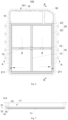
Fig. 6 is a top view of the lower battery mounting box ofFig. 5 ; -
Fig. 7 is a sectional view ofFig. 6 taken along line A-A; -
Fig. 8 is an enlarged view ofFig. 7 at I; -
Fig. 9 is a sectional view ofFig. 6 taken along line B-B; -
Fig. 10 is an enlarged view ofFig. 9 at II; -
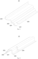
Fig. 11 is a structural diagram of the longitudinal beam ofFig. 5 ; -
Fig. 12 is a structural diagram of the crossbeam ofFig. 5 ; -
Fig. 13 is a structural diagram of the guiding structure ofFig. 5 ; and -
Fig. 14 is a structural diagram of the support structure ofFig. 4 . - The meanings of the attached markings are as follows:
100 lower battery mounting box; 10 box; 11 accommodating space; 12 pressure relief hole; 13 frame; 14 base plate; 15 connecting flange; 151 connecting hole; 20 beam; 21 pressure relief channel; 22 longitudinal beam; 221 first communicating opening; 222 first support curved wall; 223 first welded flange; 224 first transition wall; 23 crossbeam; 231 second support curved wall; 232 second welded flange; 233 second transition wall; 234 second communicating opening; 30 guiding structure; 31 lateral wall; 32 top wall; 40 mounting structure; 41 mounting position; 200 battery pack; 50 tray; 60 upper cover; 70 support structure; 71 first support beam; 711 first flange; 72 second support beam; 721 second flange; 73 air avoidance gap. - The present disclosure is further described below in conjunction with the attached drawings.
- Referring to
Figs. 3-14 , provided in the first embodiment of the present disclosure is a lowerbattery mounting box 100, including abox 10 and abeam 20. - Referring to
Figs. 3-6 , anaccommodating space 11 for a battery module is formed in thebox 10, and thebox 10 is provided with apressure relief hole 12; and thebeam 20 is provided in theaccommodating space 11 for supporting atray 50, in which thebeam 20 is formed by a process of bending or stamping, apressure relief channel 21 is formed by enclosing between thebeam 20 and interior walls of thebox 10, and theaccommodating space 11, thepressure relief channel 21 and thepressure relief hole 12 are sequentially in communication. - By adopting the lower
battery mounting box 100 mentioned above, thebeam 20 is formed by a process of bending or stamping, providing the following beneficial effects with respect to the beam of profile: Thebeam 20 with a simple structure is a sheet metal member, with higher forming efficiency, in which apressure relief channel 21 is formed by enclosing between thebeam 20 and interior walls of thebox 10. Compared to the manner in which the beam itself forms a pressure relief channel, the internal walls of thebeam 20 and thebox 10 are connected to form apressure relief channel 21, which makes full use of the space inside thebox 10, reduces the occupied space inside thebox 10, allows more batteries to be set up, enhances the power supply of the battery pack, also allows thebeam 20 to be shaped in different sizes according to the required size of thepressure relief channel 21, thereby allowing adaptive adjustments and greater adaptability. - In the present implementation, the
beam 20 is arranged to support thetray 50, and thetray 50 is arranged to support cylindrical batteries. - In the present implementation, the
box 10 is formed integrally with the stamping process, which provides a simple forming method of thebox 10 and a high forming efficiency compared to the manner in which the box is formed by extrusion molding. Thebox 10 is formed integrally by the stamping process, which forms aframe 13 and abase plate 14 simultaneously when forming, avoiding a connection step between theframe 13 and thebase plate 14 afterwards, providing a higher forming efficiency. Also, no connection seam is between theframe 13 and thebase plate 14 since thebox 10 is formed integrally, which allows thebox 10 to have a higher structural strength. - Specifically, in the present implementation, the
box 10 is made of high-strength steel. Compared to the profile box made of aluminum material, the strength of the high-strength steel is three to four times of that of the aluminum, which leads to meeting the structural strength requirements with a relatively low thickness of high-strength steel. For example, the high-strength steel with a thickness of 1.2mm is sufficient, which allows the entire weight of thesheet metal box 10 to be lower than that of the aluminum profile box, so as to achieve a lightweight aim. Additionally, in the present implementation, thebox 10 also takes advantage of reducing costs, since the price of the high-strength steel is lower than that of the aluminum. - In the present implementation, the
box 10 is applied for the mounting of cylindrical batteries, in which thebox 10 is provided with apressure relief hole 12, and thepressure relief hole 12 is in communication with theaccommodating space 11. A pressure relief chamber is formed between thetray 50 and thebase plate 14 when thebox 10 supports thetray 50, i.e., theaccommodating space 11 is divided into two sections by thetray 50, in which the upper section is a mounting space for batteries and the lower section is a pressure relief chamber. - Specifically, the
beam 20 serves as an intermediary in communicating the pressure relief chamber to thepressure relief hole 12. - Referring to
Figs. 3-6 , and11-12 , in the present implementation, thebeam 20 includes alongitudinal beam 22 and acrossbeam 23, thepressure relief channels 21 corresponding to thelongitudinal beam 22 and thepressure relief channels 21 corresponding to thecrossbeam 23 are in communication with each other, thelongitudinal beam 22 is provided with a first communicatingopening 221 in communication with theaccommodating space 11 and thepressure relief channel 21, and thepressure relief channel 21 formed by enclosing between thecrossbeam 23 and thebox 10 is in communication with thepressure relief hole 12. That is, when the battery requires pressure relief in case of thermal runaway, the pressure flows sequentially through the first connecting opening 221, thepressure relief channel 21 between thelongitudinal beam 22 and thebox 10, thepressure relief channel 21 between thecrossbeam 23 and thebox 10, and thepressure relief hole 12, and is finally relieved from thepressure relief hole 12 on thebox 10. Also, by adopting thecrossbeam 23 to connect thebox 10, since the mounting area of the liquid-cooling system, the wiring harness and the Battery Management System (hereinafter referred as BMS) is required to be formed between thecrossbeam 23 and theframe 13, the guidingstructure 30 connecting thecrossbeam 23 and thebox 10 is provided in the same mounting area as that of the liquid-cooling system, the wiring harness and the BMS, so that the occupying space of the guidingstructure 30 is reasonably compatible with the mounting space of the liquid-cooling system, the wiring harness and the BMS. Compared to the manner of connecting the guidingstructure 30 between thelongitudinal beam 22 and thebox 10, it is in such case necessary to increase the extension width along an extension direction of thecrossbeam 23, so as to connect the guidingstructure 30 between thecrossbeam 23 and thebox 10, which is conducive to reasonably narrowing the occupying space of the battery box. - Specifically, in the present implementation, the
beam 20 includes twolongitudinal beams 22 and twocrossbeams 23, in which four of them are enclosed to form a rectangular shape. Thecrossbeam 23 proximal to thepressure relief hole 12 is in communication with twolongitudinal beams 22, and thecrossbeam 23 distal to thepressure relief hole 12 is not in communication with thelongitudinal beams 22. - It is to be understood that both parallel
longitudinal beams 22 are provided with a first communicatingopening 221. - Referring to
Figs. 7-12 , in an implementation of the present disclosure, thebeam 20 is formed by a process of bending or stamping, i.e., both thecrossbeam 23 and thelongitudinal beam 22 are formed by a process of bending or stamping, which allows the formation of acrossbeam 23 structure and alongitudinal beam 22 structure as required. - Since cylindrical batteries are required to be supported by the
tray 50, for facilitating support for thetray 50, in the present implementation, thelongitudinal beam 22 is provided with a first support curvedwall 222 and thecrossbeam 23 is provided with a second supportcurved wall 231, in which the first supportcurved wall 222 and the second supportcurved wall 231 are provided to support thetray 50 collectively, so that the support curved walls support thetray 50 by providing support curved walls on both thelongitudinal beam 22 and thecrossbeam 23, which allows a certain area for both thecrossbeam 23 and thelongitudinal beam 22 of steel structure to be in contact with thetray 50. The support area is increased by the support curved walls, which ensures the stability of the support of battery modules by thecrossbeam 23 and thelongitudinal beam 22. That is, two first supportcurved walls 222 on twolongitudinal beams 22 and two second support curvedwalls 231 on twocrossbeams 23 support thetray 50 collectively when supporting thetray 50. - In the present implementation, the
longitudinal beam 22 and thecrossbeam 23 have their own mounting means when thebeam 20 is connected to thebox 10. Specifically, thebox 10 includes aframe 13 and abase plate 14 vertically connected thereto, thelongitudinal beam 22 is connected to theframe 13 and thebase plate 14, and thecrossbeam 23 is connected to thebase plate 14. - Referring to
Figs. 8 and11 , for ensuring the connection stability between thebeam 20 and thebox 10, thelongitudinal beam 22 is provided with two firstwelded flanges 223 in a width direction of thelongitudinal beam 22, the first supportcurved wall 222 is connected between two firstwelded flanges 223, one of the firstwelded flanges 223 is welded to theframe 13, and another of the firstwelded flanges 223 is welded to thebase plate 14, so that a circulation channel for the flow of air, i.e., apressure relief channel 21, is formed by enclosing between thelongitudinal beam 22 and thebox 10; and/or thecrossbeam 23 is provided with two secondwelded flanges 232 in a width direction of thecrossbeam 23, the second supportcurved wall 231 is connected between two secondwelded flanges 232, both secondwelded flanges 232 are welded to thebase plate 14, so that a circulation channel for the flow of air, i.e., apressure relief channel 21, is formed by enclosing between thecrossbeam 23 and thebase plate 14. - It is to be understood that, since both the
longitudinal beam 22 and thecrossbeam 23 are provided with support curved walls and welded flanges, for securing the forming shape of thelongitudinal beam 22 and thecrossbeam 23, one of the firstwelded flanges 223 of thelongitudinal beam 22 is transitionally connected to the first supportingcurved surface wall 222 by means of afirst transition wall 224, and at least one of the secondwelded flanges 232 of thelongitudinal beam 22 is transitionally connected to the second supportingcurved surface wall 231 by means of asecond transition wall 233. - In the present implementation, the
first transition wall 224 and thesecond transition wall 233 are arc-shaped, which are bent in a direction distal to thepressure relief channel 21 so as to be transitionally adapted to the shape of the support curved wall and the welded flange. - Additionally, for ensuring the sealing of both the
longitudinal beam 22 and thecrossbeam 23 when connected to thebox 10, the first weldedflange 223 and/or the second weldedflange 232 are/is provided with a first sealing adhesive where welded to thebox 10. That is, the areas where thelongitudinal beam 22 and thecrossbeam 23 are welded to theframe 13 and thebase plate 14, respectively, are further coated with a first sealing adhesive, so as to further ensure the connection sealing of thelongitudinal beam 22 and thecrossbeam 23 on thebox 10 by means of the first sealing adhesive. - Referring to
Figs. 3-8 ,9 ,10 and13 , in an implementation of the present disclosure, the lowerbattery mounting box 100 further includes a guidingstructure 30 since thebeam 20 is required to be in communication with thepressure relief hole 12 on theframe 13. The guidingstructure 30 is arranged to be in communication between thebeam 20 and thepressure relief hole 12, i.e., both ends of the guidingstructure 30 are in communication between thecrossbeam 23 and thepressure relief hole 12, so that the air guided from thelongitudinal beam 22 and thecrossbeam 23 is directed to thepressure relief hole 12 to release the air through a pressure relief valve provided at thepressure relief hole 12. - It should be understood that, a height of both the
longitudinal beam 22 and thecrossbeam 23 is required to be lower than that of theframe 13, since thelongitudinal beam 22 and thecrossbeam 23 are provided within theframe 13. Therefore, when opening thepressure relief hole 12, a setting height of thepressure relief hole 12 is configured to be higher than a height of the connecting channel in order to facilitate the mounting of the pressure relief valve. When setting the guidingstructure 30 of the present implementation, an opening size of the guidingstructure 30 is gradually increased from thebeam 23 to thepressure relief hole 12 so that the opening height of thepressure relief hole 12 may be higher than a height of thepressure relief channel 21 in thebeam 20, thereby achieving the effect of directing the air from a low-positionedbeam 20 to a high-positionedpressure relief hole 12. - Referring to
Fig. 13 , in the present implementation, the guidingstructure 30 includes two oppositelateral walls 31 and atop wall 32 connected to twolateral walls 31, in which twolateral walls 31 and atop wall 32 form a three-sided communicating structure. End edges of twolateral walls 31 corresponding to a side with an outlet are arranged to be connected to theframe 13 and in communication with thepressure relief hole 12, end edges of twolateral walls 31 corresponding to a lower connecting opening are arranged to be connected to thebase plate 14, and end edges of twolateral walls 31 corresponding to a side with an inlet are arranged to be connected to thecrossbeam 23, so as to achieve that the guidingstructure 30 is enclosed with theframe 13, thebase plate 14, and thecrossbeam 23 respectively to form a channel for guiding air, and the air is directed to the guidingstructure 30 by thepressure relief channel 21 enclosed by thecrossbeam 23 in sequence, then is directed to thepressure relief hole 12 by the guidingstructure 30, and finally flows out from thepressure relief hole 12. Each end edge of the guidingstructure 30 may be welded to thebox 10 and thecrossbeam 23 when the guidingstructure 30 is mounted, respectively, so as to ensure airtightness when the air flows. - Specifically, referring to
Fig. 12 , in the present implementation, thecrossbeam 23 is provided with a second communicatingopening 234, in which the second communicatingopening 234 is in communication with the guidingstructure 30. - Additionally, referring to
Figs. 1-6 , in the present implementation, the lowerbattery mounting box 100 further includes a mountingstructure 40, in which the mountingstructure 40 is connected to thebox 10, and the mountingstructure 40 is provided with a plurality of mountingpositions 41 spaced apart. That is, in the present implementation, the mountingstructure 40 is formed integrally, and a plurality of mountingpositions 41 is provided on the integrally formed mountingstructure 40, so that it is sufficient to weld only one mountingstructure 40 to thebox 10 when mounting the mountingstructure 40 to thebox 10, which not only improves the forming efficiency of the mountingstructure 40, but also improves the connecting efficiency of the mountingstructure 40 and thebox 10. - Referring to
Figs. 4-6 , and14 , for ensuring the support stability of thetray 50 and the support strength of thebox 10, the lowerbattery mounting box 100 further includes asupport structure 70, in which thesupport structure 70 is provided in theaccommodating space 11, and the first support curvedwall 222 and the second support curvedwall 231 are provided to support thetray 50 collectively. Asupport structure 70 is provided in the box to support thetray 50, so as to enhance the support strength of thebase plate 14 of thebox 10, which avoids collapsing thebase plate 14 after mounting the battery module on thetray 50. - The
support structure 70 is provided with anair avoidance gap 73 for flowing air. Theair avoidance gap 73 is provided to allow the pressure to flow through theair avoidance gap 73 to flow into the first connectingopening 221 of thelongitudinal beam 22 when the cylindrical battery is relieved to a lower side of thetray 50, avoiding that thesupport structure 70 affects the flow of air in the space formed between thetray 50 and thebase plate 14, after the support for thetray 50 is provided. - Further, in the present implementation, the
air avoidance gap 73 is formed by recessing a part of thesupport structure 70 towards thebase plate 14 of thebox 10, which facilitates the formation of the avoidance gap. That is, theair avoidance gap 73 is formed simultaneously when forming thesupport structure 70. In other implementations, a through-hole may be provided on thesupport structure 70 in a length direction of thelongitudinal beam 22, which may also achieve the flow of air by the through-hole. - Specifically, two
longitudinal beams 22 and twocrossbeams 23 are provided in the present implementation, in which four of them are enclosed to form a rectangular shape, and thesupport structure 70 is provided in the structure with the rectangular shape. Corresponding to the structure of thebeam 20, with thebox 10 forming integrally by a stamping process, thebox 10 may suffer from insufficient load bearing strength. Therefore, in the present implementation, thesupport structure 70 is in a shape of a cross, positioned in the enclosing space enclosed by thelongitudinal beam 22 and thecrossbeam 23, i.e., positioned in the structure with the rectangular shape. Thebeam 20 and thesupport structure 70 are combined to form a structure with four rectangular shapes, i.e., thesupport structure 70 is in contact with both thelongitudinal beam 23 and thecrossbeam 22, which ensures the structural strength of thebase plate 14 collectively, avoiding collapse. In such a setup, the load bearing problem of thebase plate 14 is solved. - Specifically, in the present implementation, the
support structure 70 includes afirst support beam 71 and asecond support beam 72 provided in intersection, thefirst support beam 71 is in parallel to thelongitudinal beam 22, thesecond support beam 72 is in parallel to thecrossbeam 23, and thefirst support beam 71 and/or thesecond support beam 72 are/is provided with theair avoidance gap 73, so as to provide theair avoidance gap 73 on thefirst support beam 71 and/or thesecond support beam 72, avoiding that thesupport structure 70 affects the flow of air in the space formed between thetray 50 and thebase plate 14, after the support for thetray 50 is provided. - Specifically, in the present implementation, the
air avoidance gap 73 is provided on thesecond support beam 72, in which the air flows through theair avoidance gap 73 on thesecond support beam 72. The air is directed into the first connectingopening 221 of thelongitudinal beam 22 due to the guiding effect of thelongitudinal beam 22 and thefirst support beam 71 parallel to thelongitudinal beam 41, i.e., it is conducive to the smooth flow of the air in a direction towards thelongitudinal beam 22, and to enhancing the efficiency of the pressure relief. Specifically, in the present implementation, refer toFig. 6 for a diagram of the airflow within thebox 10. With the guiding effect of thelongitudinal beam 22 and thefirst support beam 71, the air flows through theair avoidance gap 73 to the first connectingopening 221 of thelongitudinal beam 22, flows through thepressure relief channel 21 formed by thelongitudinal beam 22 and an interior wall of thebox 10, flows to thecrossbeam 23 and the interior wall of thebox 10 to form thepressure relief channel 21, then flows through the second connecting opening 234 on thecrossbeam 23 to the guidingstructure 30, and is finally relieved by the pressure relief holes 12 in communication with the guidingstructure 30 on thebox 10. - In the present implementation, the
first support beam 71 and thesecond support beam 72 are connected by a lap joint when setting thesupport structure 70 with the shape of a cross. That is, one reinforcing beam laps over another reinforcing beam. For example, thefirst support beam 71 may lap over thesecond support beam 72 or thesecond support beam 72 may lap over thefirst support beam 71, which may both achieve the effect of overlapping connection. - Specifically, in the present implementation, the
second support beam 72 laps over thefirst support beam 71. In such a setup, in the present implementation, thefirst support beam 71 and thesecond support beam 72 are in overlapping connection, which avoids connecting the process of connecting them, e.g., the process of welding them together, which improves the mounting efficiency of thesupport structure 70. - It should be noted that, in the present implementation, corresponding to that two
longitudinal beams 22 are in communication with onecrossbeam 23, thesecond support beam 72 is provided with twoair avoidance gaps 73, and twoair avoidance gaps 73 are provided spaced apart with thefirst support beam 71 as a separating beam. In other implementations, moreair avoidance gaps 73 may be provided on each side of thefirst support beam 71, e.g., two or more, which is not limited hereby. - In the present implementation, both the
first support beam 71 and thesecond support beam 72 are welded to thebase plate 14 when mounting thesupport structure 70, so as to ensure the strength of connection between each of thefirst support beam 71 and thesecond support beam 72 to thebase plate 14. Also, the integrity of thebase plate 14 is ensured by the connection between each of thefirst support beam 71 and thesecond support beam 72 with thebase plate 14, as compared to a rivet or bolt connection. - Specifically, referring to
Fig. 14 , when welding each of thefirst support beam 71 and thesecond support beam 72 to thebase plate 14, thefirst support beam 71 is provided with afirst flange 711 in parallel to thebase plate 14, in which thefirst flange 711 is arranged to be in welded connection with thebase plate 14, and thesecond support beam 72 is provided with asecond flange 721 in parallel to thebase plate 14, in which thesecond flange 721 is arranged to be in welded connection with thebase plate 14, so that the connection area is increased when welding each of thefirst support beam 71 and thesecond support beam 72 to thebase plate 14 by providing thefirst flange 711 and thesecond flange 721, which ensures the welded strength of both thefirst support beam 71 and thesecond support beam 72 to thebase plate 14. - Referring to
Fig. 1 and Fig. 2 , provided in the second embodiment of the present disclosure is abattery pack 200, including a battery module (not shown in figures), atray 50, anupper cover 60, and a lowerbattery mounting box 100 mentioned above. - The lower
battery mounting box 100 is arranged to mount the battery module (not shown in figures). Thetray 50 is provided in theaccommodating space 11 of the battery box, provided on thebeam 20, arranged to support the battery module. Theupper cover 60 is connected to the lowerbattery mounting box 100 for covering the lowerbattery mounting box 100. - Further, for ensuring the sealing of the upper and lower areas of the
tray 50 after the battery module is placed on thetray 50, for ensuring the operational security of the battery, thebattery pack 200 further includes a second sealing adhesive after thetray 50 is provided on thelongitudinal beam 22 and thecrossbeam 23. The second sealing adhesive is filled with a bottom of the battery module and is supported by thetray 50, i.e., the second sealing adhesive fills the gap between thetray 50 and the battery module and extends to the overlapping connection of thetray 50 to thecrossbeam 23 and thelongitudinal beam 22. The second sealing adhesive is provided to ensure the sealing of the upper and lower areas of thetray 50 after the battery module is placed on thetray 50, which divides theaccommodating space 11 within thebox 10 into an upper area and a lower area. The air flows below thetray 50 and avoids flowing upwards when the battery module is relieving pressure, so as to form a separate pressure relief channel and achieve the effect of separation of heat and electricity, which ensures the safety of the battery use. Also, the second sealing adhesive combines the battery module and thetray 50 into a single unit, which allows the battery module and thetray 50 to provide greater structural strength. - Further, referring to
Figs. 1-6 , thebattery pack 200 further includes anupper cover 60, since thebox 10 of the present implementation is formed by stamping. For facilitating the mounting between thebox 10 and theupper cover 60, an upper edge of thebox 10 is formed with a connectingflange 15 in a peripheral direction away from a center of thebox 10, the connectingflange 15 is extended in a direction perpendicular to a height direction of thebox 10, and theupper cover 60 is connected to the connectingflange 15 to cover thebox 10. An upper edge of thebox 10 is formed with a connectingflange 15 in a peripheral direction, which facilitates the connection between thebox 10 and theupper cover 60, ensuring the connection sealing between theupper cover 60 and thebox 10, thereby sealing the battery modules inside the lowerbattery mounting box 100. - Specifically, in the present implementation, the connecting
flange 15 is provided with a plurality of connectingholes 151 through which thebox 10 is in bolted connection with theupper cover 60, which achieves the sealing between theupper cover 60 and thebox 10.
Claims (16)
- A lower battery mounting box (100), comprising:a box (10), wherein an accommodating space (11) for a battery module is formed in the box (10), and the box (10) is provided with a pressure relief hole (12); anda beam (20), provided in the accommodating space (11), wherein the beam (20) is a sheet metal member and formed by a process of bending or stamping, a pressure relief channel (21) is formed by enclosing between the beam (20) and interior walls of the box (10), and the accommodating space (11), the pressure relief channel (21) and the pressure relief hole (12) are sequentially in communication.
- The lower battery mounting box (100) according to claim 1, wherein the beam (20) comprises a longitudinal beam (22) and a crossbeam (23), the pressure relief channels (21) corresponding to the longitudinal beam (22) and the pressure relief channels (21) corresponding to the crossbeam (23) are in communication with each other, the longitudinal beam (22) is provided with a first communicating opening (221) in communication with the accommodating space (11) and the pressure relief channel (21), and the pressure relief channel (21) formed by enclosing between the crossbeam (23) and the box (10) is in communication with the pressure relief hole (12).
- The lower battery mounting box (100) according to claim 2, wherein the longitudinal beam (22) is provided with a first support curved wall (222), the crossbeam (23) is provided with a second support curved wall (231), and the first support curved wall (222) and the second support curved wall (231) are arranged to support a tray (50) collectively.
- The lower battery mounting box (100) according to claim 3, wherein the box (10) comprises a frame (13) and a base plate (14) vertically connected thereto, the longitudinal beam (22) is provided with two first welded flanges (223) in a width direction of the longitudinal beam (22), the first support curved wall (222) is connected between two first welded flanges (223), one of the first welded flanges (223) is welded to the frame (13), and another of the first welded flanges (223) is welded to the base plate (14) and is connected to the first support curved wall (222) with a first transition wall (224); and/or
the crossbeam (23) is provided with two second welded flanges (232) in a width direction of the crossbeam (23), the second support curved wall (231) is connected between two second welded flanges (232), both two second welded flanges (232) are in welded connection with the base plate (14), and at least one of the second welded flanges (232) is connected to the second support curved wall (231) with a second transition wall (233). - The lower battery mounting box (100) according to claim 4, wherein the first welded flange (223) and/or the second welded flange (232) are/is provided with a first sealing adhesive where welded to the box (10).
- The lower battery mounting box (100) according to any one of claims 1-5, wherein the lower battery mounting box (100) further comprises a guiding structure (30), and both ends of the guiding structure (30) are in communication between the pressure relief hole (12) and the pressure relief channel (21) of the beam (20).
- The lower battery mounting box (100) according to claim 6, wherein an opening size of the guiding structure (30) is gradually increased from the beam (20) to the pressure relief hole (12), so that a setting height of the pressure relief hole (12) is higher than a height of the pressure relief channel (21) of the beam (20).
- The lower battery mounting box (100) according to any one of claims 3-5, wherein the lower battery mounting box (100) further comprises a support structure (70), the support structure (70) is provided in the accommodating space (11), and the first support curved wall (222) and the second support curved wall (231) are provided to support the tray (50) collectively.
- The lower battery mounting box (100) according to claim 8, wherein the support structure (70) is provided with an air avoidance gap (73) for flowing air.
- The lower battery mounting box (100) according to claim 9, wherein the air avoidance gap (73) is formed by recessing a part of the support structure (70) towards the base plate (14) of the box (10).
- The lower battery mounting box (100) according to claim 9 or 10, wherein the support structure (70) comprises a first support beam (71) and a second support beam (72) provided in intersection, the first support beam (71) is in parallel to the longitudinal beam (22), the second support beam (72) is in parallel to the crossbeam (23), and the first support beam (71) and/or the second support beam (72) are/is provided with the air avoidance gap (73).
- The lower battery mounting box (100) according to claim 11, wherein the first support beam (71) is provided with a first flange (711) in parallel to the base plate (14), the first flange (711) is arranged to be in welded connection with the base plate (14), the second support beam (72) is provided with a second flange (721) in parallel to the base plate (14), and the second flange (721) is arranged to be in welded connection with the base plate (14).
- The lower battery mounting box (100) according to any one of claims 1-12, wherein the lower battery mounting box (100) comprises a mounting structure (40), the mounting structure (40) is connected to an exterior side of the box (10), and the mounting structure (40) is provided with a plurality of mounting positions (41) spaced apart.
- The battery pack (200), comprising:a battery module;a lower battery mounting box (100) as claimed in any one of claims 1-13;
a tray (50), provided in the accommodating space (11) of the lower battery mounting box (100), provided on the beam (20), arranged to support the battery module; andan upper cover (60), connected to the lower battery mounting box (100), arranged to cover the lower battery mounting box (100). - The battery pack (200) according to claim 14, wherein the battery pack (200) further comprises a second sealing adhesive and the second sealing adhesive is filled with a bottom of the battery module and is supported by the tray (50), and/or
the box (100) is integrally formed by stamping process. - The battery pack (200) according to claim 15, wherein an upper edge of the box (10) is formed with a connecting flange (15) in a peripheral direction away from a center of the box (10), the connecting flange (15) is extended in a direction perpendicular to a height direction of the box (10), and the upper cover (60) is connected to the connecting flange (15) to cover the box (10).
Applications Claiming Priority (2)
| Application Number | Priority Date | Filing Date | Title |
|---|---|---|---|
| CN202320713617.2U CN219873817U (en) | 2023-03-31 | 2023-03-31 | Battery mounting box and battery pack |
| CN202320713659.6U CN219873818U (en) | 2023-03-31 | 2023-03-31 | Battery lower mounting box and battery pack |
Publications (2)
| Publication Number | Publication Date |
|---|---|
| EP4439799A2 true EP4439799A2 (en) | 2024-10-02 |
| EP4439799A3 EP4439799A3 (en) | 2025-01-22 |
Family
ID=90717322
Family Applications (1)
| Application Number | Title | Priority Date | Filing Date |
|---|---|---|---|
| EP24167880.4A Pending EP4439799A3 (en) | 2023-03-31 | 2024-03-29 | Lower battery mounting box and battery pack |
Country Status (3)
| Country | Link |
|---|---|
| EP (1) | EP4439799A3 (en) |
| DE (1) | DE202024103103U1 (en) |
| WO (1) | WO2024199463A1 (en) |
Family Cites Families (14)
| Publication number | Priority date | Publication date | Assignee | Title |
|---|---|---|---|---|
| CN207425965U (en) * | 2017-10-30 | 2018-05-29 | 东软集团股份有限公司 | A kind of battery pack housing |
| KR102952415B1 (en) * | 2020-04-29 | 2026-04-14 | 주식회사 엘지에너지솔루션 | Battery pack with improved fixing structure and gas exhausting structure, and Electronic device and Vehicle comprising the Same |
| KR102922132B1 (en) * | 2020-04-29 | 2026-02-02 | 주식회사 엘지에너지솔루션 | Battery pack and device including the same |
| CN212587659U (en) * | 2020-08-17 | 2021-02-23 | 蜂巢能源科技有限公司 | Battery pack lower case and battery pack having the same |
| DE102021100659A1 (en) * | 2021-01-14 | 2021-03-18 | Daimler Ag | Battery case and battery |
| CN216055066U (en) * | 2021-06-28 | 2022-03-15 | 长城汽车股份有限公司 | Box, battery package and vehicle under battery package |
| CN216529223U (en) * | 2021-11-18 | 2022-05-13 | 湖北亿纬动力有限公司 | a battery pack |
| CN217062363U (en) * | 2022-03-25 | 2022-07-26 | 中创新航科技股份有限公司 | Battery box and battery inserting box |
| CN217062360U (en) * | 2022-03-25 | 2022-07-26 | 中创新航科技股份有限公司 | Battery box and energy storage equipment |
| CN217589301U (en) * | 2022-04-20 | 2022-10-14 | 湖北亿纬动力有限公司 | Power battery and electric vehicle |
| CN115548548A (en) * | 2022-10-28 | 2022-12-30 | 南京创源天地动力科技有限公司 | Battery pack of electric forklift |
| KR20240084976A (en) * | 2022-12-07 | 2024-06-14 | 에스케이온 주식회사 | Battery Pack |
| CN115764146A (en) * | 2022-12-19 | 2023-03-07 | 湖北亿纬动力有限公司 | Battery pack |
| CN219873818U (en) * | 2023-03-31 | 2023-10-20 | 惠州亿纬锂能股份有限公司 | Battery lower mounting box and battery pack |
-
2024
- 2024-03-29 EP EP24167880.4A patent/EP4439799A3/en active Pending
- 2024-03-29 WO PCT/CN2024/084872 patent/WO2024199463A1/en not_active Ceased
- 2024-03-29 DE DE202024103103.2U patent/DE202024103103U1/en active Active
Also Published As
| Publication number | Publication date |
|---|---|
| DE202024103103U1 (en) | 2024-08-01 |
| WO2024199463A1 (en) | 2024-10-03 |
| EP4439799A3 (en) | 2025-01-22 |
Similar Documents
| Publication | Publication Date | Title |
|---|---|---|
| EP4148874B1 (en) | Battery box | |
| US11894510B2 (en) | Battery pack and vehicle | |
| US11926244B2 (en) | Method for producing a battery carrier for the mounting of an electric battery module | |
| EP4447215A1 (en) | Battery module, battery pack, and vehicle | |
| US11990635B2 (en) | Frame structure assembly kit, battery module, and method for manufacturing battery module | |
| CN112448086B (en) | Battery trays, battery packs and vehicles | |
| CN212659592U (en) | Cooling device for a power battery system and power battery system for a vehicle | |
| CN111106268A (en) | Liquid cooling battery box | |
| EP4404331A1 (en) | Air cooling structure and battery pack | |
| EP4726898A2 (en) | Battery module and electric vehicle | |
| EP4439799A2 (en) | Lower battery mounting box and battery pack | |
| EP4492549A1 (en) | Battery pack | |
| US20240332723A1 (en) | Lower Battery Mounting Box and Battery Pack | |
| CN212725481U (en) | Battery pack box and battery pack with same | |
| WO2026077228A1 (en) | Battery pack | |
| WO2023174308A1 (en) | Edge beam used for battery tray, battery tray, battery pack, and vehicle | |
| CN219873818U (en) | Battery lower mounting box and battery pack | |
| CN109560218B (en) | Lower shell for battery pack and battery pack | |
| CN119170980B (en) | Assembly method of power battery pack, vehicle and power battery pack | |
| CN211238324U (en) | Battery box structure and power battery pack | |
| CN220856768U (en) | Battery module and battery pack | |
| CN220253325U (en) | Liquid cooling electric box and integrated battery package | |
| CN216529038U (en) | Liquid cooling board, battery package tray and have its battery package | |
| CN212209580U (en) | Battery PACK box | |
| CN219040626U (en) | Battery pack and box thereof |
Legal Events
| Date | Code | Title | Description |
|---|---|---|---|
| PUAI | Public reference made under article 153(3) epc to a published international application that has entered the european phase |
Free format text: ORIGINAL CODE: 0009012 |
|
| STAA | Information on the status of an ep patent application or granted ep patent |
Free format text: STATUS: REQUEST FOR EXAMINATION WAS MADE |
|
| 17P | Request for examination filed |
Effective date: 20240329 |
|
| AK | Designated contracting states |
Kind code of ref document: A2 Designated state(s): AL AT BE BG CH CY CZ DE DK EE ES FI FR GB GR HR HU IE IS IT LI LT LU LV MC ME MK MT NL NO PL PT RO RS SE SI SK SM TR |
|
| PUAL | Search report despatched |
Free format text: ORIGINAL CODE: 0009013 |
|
| STAA | Information on the status of an ep patent application or granted ep patent |
Free format text: STATUS: EXAMINATION IS IN PROGRESS |
|
| AK | Designated contracting states |
Kind code of ref document: A3 Designated state(s): AL AT BE BG CH CY CZ DE DK EE ES FI FR GB GR HR HU IE IS IT LI LT LU LV MC ME MK MT NL NO PL PT RO RS SE SI SK SM TR |
|
| RIC1 | Information provided on ipc code assigned before grant |
Ipc: H01M 50/342 20210101ALI20241219BHEP Ipc: H01M 50/224 20210101ALI20241219BHEP Ipc: H01M 50/209 20210101ALI20241219BHEP Ipc: H01M 50/204 20210101ALI20241219BHEP Ipc: H01M 10/625 20140101ALI20241219BHEP Ipc: H01M 10/613 20140101AFI20241219BHEP |
|
| 17Q | First examination report despatched |
Effective date: 20250115 |
|
| GRAP | Despatch of communication of intention to grant a patent |
Free format text: ORIGINAL CODE: EPIDOSNIGR1 |
|
| STAA | Information on the status of an ep patent application or granted ep patent |
Free format text: STATUS: GRANT OF PATENT IS INTENDED |
|
| INTG | Intention to grant announced |
Effective date: 20260205 |