EP4439795A2 - Batteriemodul - Google Patents
Batteriemodul Download PDFInfo
- Publication number
- EP4439795A2 EP4439795A2 EP24158924.1A EP24158924A EP4439795A2 EP 4439795 A2 EP4439795 A2 EP 4439795A2 EP 24158924 A EP24158924 A EP 24158924A EP 4439795 A2 EP4439795 A2 EP 4439795A2
- Authority
- EP
- European Patent Office
- Prior art keywords
- flow path
- vent
- battery
- module
- battery cells
- Prior art date
- Legal status (The legal status is an assumption and is not a legal conclusion. Google has not performed a legal analysis and makes no representation as to the accuracy of the status listed.)
- Pending
Links
Images




Classifications
-
- H—ELECTRICITY
- H01—ELECTRIC ELEMENTS
- H01M—PROCESSES OR MEANS, e.g. BATTERIES, FOR THE DIRECT CONVERSION OF CHEMICAL ENERGY INTO ELECTRICAL ENERGY
- H01M50/00—Constructional details or processes of manufacture of the non-active parts of electrochemical cells other than fuel cells, e.g. hybrid cells
- H01M50/30—Arrangements for facilitating escape of gases
- H01M50/35—Gas exhaust passages comprising elongated, tortuous or labyrinth-shaped exhaust passages
- H01M50/358—External gas exhaust passages located on the battery cover or case
-
- H—ELECTRICITY
- H01—ELECTRIC ELEMENTS
- H01M—PROCESSES OR MEANS, e.g. BATTERIES, FOR THE DIRECT CONVERSION OF CHEMICAL ENERGY INTO ELECTRICAL ENERGY
- H01M50/00—Constructional details or processes of manufacture of the non-active parts of electrochemical cells other than fuel cells, e.g. hybrid cells
- H01M50/30—Arrangements for facilitating escape of gases
- H01M50/35—Gas exhaust passages comprising elongated, tortuous or labyrinth-shaped exhaust passages
- H01M50/367—Internal gas exhaust passages forming part of the battery cover or case; Double cover vent systems
-
- H—ELECTRICITY
- H01—ELECTRIC ELEMENTS
- H01M—PROCESSES OR MEANS, e.g. BATTERIES, FOR THE DIRECT CONVERSION OF CHEMICAL ENERGY INTO ELECTRICAL ENERGY
- H01M10/00—Secondary cells; Manufacture thereof
- H01M10/04—Construction or manufacture in general
- H01M10/0468—Compression means for stacks of electrodes and separators
-
- H—ELECTRICITY
- H01—ELECTRIC ELEMENTS
- H01M—PROCESSES OR MEANS, e.g. BATTERIES, FOR THE DIRECT CONVERSION OF CHEMICAL ENERGY INTO ELECTRICAL ENERGY
- H01M10/00—Secondary cells; Manufacture thereof
- H01M10/60—Heating or cooling; Temperature control
- H01M10/61—Types of temperature control
- H01M10/613—Cooling or keeping cold
-
- H—ELECTRICITY
- H01—ELECTRIC ELEMENTS
- H01M—PROCESSES OR MEANS, e.g. BATTERIES, FOR THE DIRECT CONVERSION OF CHEMICAL ENERGY INTO ELECTRICAL ENERGY
- H01M10/00—Secondary cells; Manufacture thereof
- H01M10/60—Heating or cooling; Temperature control
- H01M10/64—Heating or cooling; Temperature control characterised by the shape of the cells
- H01M10/647—Prismatic or flat cells, e.g. pouch cells
-
- H—ELECTRICITY
- H01—ELECTRIC ELEMENTS
- H01M—PROCESSES OR MEANS, e.g. BATTERIES, FOR THE DIRECT CONVERSION OF CHEMICAL ENERGY INTO ELECTRICAL ENERGY
- H01M10/00—Secondary cells; Manufacture thereof
- H01M10/60—Heating or cooling; Temperature control
- H01M10/65—Means for temperature control structurally associated with the cells
- H01M10/653—Means for temperature control structurally associated with the cells characterised by electrically insulating or thermally conductive materials
-
- H—ELECTRICITY
- H01—ELECTRIC ELEMENTS
- H01M—PROCESSES OR MEANS, e.g. BATTERIES, FOR THE DIRECT CONVERSION OF CHEMICAL ENERGY INTO ELECTRICAL ENERGY
- H01M10/00—Secondary cells; Manufacture thereof
- H01M10/60—Heating or cooling; Temperature control
- H01M10/65—Means for temperature control structurally associated with the cells
- H01M10/655—Solid structures for heat exchange or heat conduction
- H01M10/6552—Closed pipes transferring heat by thermal conductivity or phase transition, e.g. heat pipes
-
- H—ELECTRICITY
- H01—ELECTRIC ELEMENTS
- H01M—PROCESSES OR MEANS, e.g. BATTERIES, FOR THE DIRECT CONVERSION OF CHEMICAL ENERGY INTO ELECTRICAL ENERGY
- H01M10/00—Secondary cells; Manufacture thereof
- H01M10/60—Heating or cooling; Temperature control
- H01M10/65—Means for temperature control structurally associated with the cells
- H01M10/655—Solid structures for heat exchange or heat conduction
- H01M10/6554—Rods or plates
-
- H—ELECTRICITY
- H01—ELECTRIC ELEMENTS
- H01M—PROCESSES OR MEANS, e.g. BATTERIES, FOR THE DIRECT CONVERSION OF CHEMICAL ENERGY INTO ELECTRICAL ENERGY
- H01M10/00—Secondary cells; Manufacture thereof
- H01M10/60—Heating or cooling; Temperature control
- H01M10/65—Means for temperature control structurally associated with the cells
- H01M10/656—Means for temperature control structurally associated with the cells characterised by the type of heat-exchange fluid
- H01M10/6561—Gases
-
- H—ELECTRICITY
- H01—ELECTRIC ELEMENTS
- H01M—PROCESSES OR MEANS, e.g. BATTERIES, FOR THE DIRECT CONVERSION OF CHEMICAL ENERGY INTO ELECTRICAL ENERGY
- H01M10/00—Secondary cells; Manufacture thereof
- H01M10/60—Heating or cooling; Temperature control
- H01M10/65—Means for temperature control structurally associated with the cells
- H01M10/656—Means for temperature control structurally associated with the cells characterised by the type of heat-exchange fluid
- H01M10/6561—Gases
- H01M10/6566—Means within the gas flow to guide the flow around one or more cells, e.g. manifolds, baffles or other barriers
-
- H—ELECTRICITY
- H01—ELECTRIC ELEMENTS
- H01M—PROCESSES OR MEANS, e.g. BATTERIES, FOR THE DIRECT CONVERSION OF CHEMICAL ENERGY INTO ELECTRICAL ENERGY
- H01M10/00—Secondary cells; Manufacture thereof
- H01M10/60—Heating or cooling; Temperature control
- H01M10/65—Means for temperature control structurally associated with the cells
- H01M10/658—Means for temperature control structurally associated with the cells by thermal insulation or shielding
-
- H—ELECTRICITY
- H01—ELECTRIC ELEMENTS
- H01M—PROCESSES OR MEANS, e.g. BATTERIES, FOR THE DIRECT CONVERSION OF CHEMICAL ENERGY INTO ELECTRICAL ENERGY
- H01M50/00—Constructional details or processes of manufacture of the non-active parts of electrochemical cells other than fuel cells, e.g. hybrid cells
- H01M50/20—Mountings; Secondary casings or frames; Racks, modules or packs; Suspension devices; Shock absorbers; Transport or carrying devices; Holders
- H01M50/204—Racks, modules or packs for multiple batteries or multiple cells
-
- H—ELECTRICITY
- H01—ELECTRIC ELEMENTS
- H01M—PROCESSES OR MEANS, e.g. BATTERIES, FOR THE DIRECT CONVERSION OF CHEMICAL ENERGY INTO ELECTRICAL ENERGY
- H01M50/00—Constructional details or processes of manufacture of the non-active parts of electrochemical cells other than fuel cells, e.g. hybrid cells
- H01M50/20—Mountings; Secondary casings or frames; Racks, modules or packs; Suspension devices; Shock absorbers; Transport or carrying devices; Holders
- H01M50/204—Racks, modules or packs for multiple batteries or multiple cells
- H01M50/207—Racks, modules or packs for multiple batteries or multiple cells characterised by their shape
- H01M50/209—Racks, modules or packs for multiple batteries or multiple cells characterised by their shape adapted for prismatic or rectangular cells
-
- H—ELECTRICITY
- H01—ELECTRIC ELEMENTS
- H01M—PROCESSES OR MEANS, e.g. BATTERIES, FOR THE DIRECT CONVERSION OF CHEMICAL ENERGY INTO ELECTRICAL ENERGY
- H01M50/00—Constructional details or processes of manufacture of the non-active parts of electrochemical cells other than fuel cells, e.g. hybrid cells
- H01M50/20—Mountings; Secondary casings or frames; Racks, modules or packs; Suspension devices; Shock absorbers; Transport or carrying devices; Holders
- H01M50/233—Mountings; Secondary casings or frames; Racks, modules or packs; Suspension devices; Shock absorbers; Transport or carrying devices; Holders characterised by physical properties of casings or racks, e.g. dimensions
- H01M50/242—Mountings; Secondary casings or frames; Racks, modules or packs; Suspension devices; Shock absorbers; Transport or carrying devices; Holders characterised by physical properties of casings or racks, e.g. dimensions adapted for protecting batteries against vibrations, collision impact or swelling
-
- H—ELECTRICITY
- H01—ELECTRIC ELEMENTS
- H01M—PROCESSES OR MEANS, e.g. BATTERIES, FOR THE DIRECT CONVERSION OF CHEMICAL ENERGY INTO ELECTRICAL ENERGY
- H01M50/00—Constructional details or processes of manufacture of the non-active parts of electrochemical cells other than fuel cells, e.g. hybrid cells
- H01M50/50—Current conducting connections for cells or batteries
- H01M50/502—Interconnectors for connecting terminals of adjacent batteries; Interconnectors for connecting cells outside a battery casing
-
- H—ELECTRICITY
- H01—ELECTRIC ELEMENTS
- H01M—PROCESSES OR MEANS, e.g. BATTERIES, FOR THE DIRECT CONVERSION OF CHEMICAL ENERGY INTO ELECTRICAL ENERGY
- H01M50/00—Constructional details or processes of manufacture of the non-active parts of electrochemical cells other than fuel cells, e.g. hybrid cells
- H01M50/50—Current conducting connections for cells or batteries
- H01M50/502—Interconnectors for connecting terminals of adjacent batteries; Interconnectors for connecting cells outside a battery casing
- H01M50/505—Interconnectors for connecting terminals of adjacent batteries; Interconnectors for connecting cells outside a battery casing comprising a single busbar
-
- H—ELECTRICITY
- H01—ELECTRIC ELEMENTS
- H01M—PROCESSES OR MEANS, e.g. BATTERIES, FOR THE DIRECT CONVERSION OF CHEMICAL ENERGY INTO ELECTRICAL ENERGY
- H01M50/00—Constructional details or processes of manufacture of the non-active parts of electrochemical cells other than fuel cells, e.g. hybrid cells
- H01M50/50—Current conducting connections for cells or batteries
- H01M50/572—Means for preventing undesired use or discharge
- H01M50/584—Means for preventing undesired use or discharge for preventing incorrect connections inside or outside the batteries
- H01M50/59—Means for preventing undesired use or discharge for preventing incorrect connections inside or outside the batteries characterised by the protection means
- H01M50/593—Spacers; Insulating plates
-
- H—ELECTRICITY
- H01—ELECTRIC ELEMENTS
- H01M—PROCESSES OR MEANS, e.g. BATTERIES, FOR THE DIRECT CONVERSION OF CHEMICAL ENERGY INTO ELECTRICAL ENERGY
- H01M50/00—Constructional details or processes of manufacture of the non-active parts of electrochemical cells other than fuel cells, e.g. hybrid cells
- H01M50/20—Mountings; Secondary casings or frames; Racks, modules or packs; Suspension devices; Shock absorbers; Transport or carrying devices; Holders
- H01M50/289—Mountings; Secondary casings or frames; Racks, modules or packs; Suspension devices; Shock absorbers; Transport or carrying devices; Holders characterised by spacing elements or positioning means within frames, racks or packs
- H01M50/291—Mountings; Secondary casings or frames; Racks, modules or packs; Suspension devices; Shock absorbers; Transport or carrying devices; Holders characterised by spacing elements or positioning means within frames, racks or packs characterised by their shape
-
- Y—GENERAL TAGGING OF NEW TECHNOLOGICAL DEVELOPMENTS; GENERAL TAGGING OF CROSS-SECTIONAL TECHNOLOGIES SPANNING OVER SEVERAL SECTIONS OF THE IPC; TECHNICAL SUBJECTS COVERED BY FORMER USPC CROSS-REFERENCE ART COLLECTIONS [XRACs] AND DIGESTS
- Y02—TECHNOLOGIES OR APPLICATIONS FOR MITIGATION OR ADAPTATION AGAINST CLIMATE CHANGE
- Y02E—REDUCTION OF GREENHOUSE GAS [GHG] EMISSIONS, RELATED TO ENERGY GENERATION, TRANSMISSION OR DISTRIBUTION
- Y02E60/00—Enabling technologies; Technologies with a potential or indirect contribution to GHG emissions mitigation
- Y02E60/10—Energy storage using batteries
Definitions
- the present disclosure relates to a battery module.
- a battery module includes battery cells connected to each other.
- a conventional battery module includes battery cells and a module case for receiving the battery cells.
- the module case of the conventional battery module exposes vent portions of the battery cells and supports the battery cells, considering the case in which a thermal runaway is generated to the battery cells.
- the present disclosure has been made in an effort to provide a battery module for easily discharging gas generated by a vent portion of a battery cell generating a thermal runaway corresponding to thermal runaways of battery cells and trapping particles included in the gas.
- the present disclosure has been made in another effort to provide a battery module for easily conveying battery cells, assembling the same, and protecting the same from external impacts.
- An embodiment of the present disclosure provides a battery module including: battery cells including vent portions disposed in a first direction; and a first module case extending in the first direction and supporting the battery cells, wherein the first module case includes a first vent flow path communicating with the vent portions, and denting and extending in the first direction, and second vent flow paths spaced from each other in a second direction traversing the first direction with the first vent flow path therebetween, extending in the first direction to support the battery cells, and directly communicating with the first vent flow path.
- the respective second vent flow paths may include a first sub flow path directly communicating with the first vent flow path and extending in the first direction; and a second sub flow path spaced from the first sub flow path in the second direction, extending in the first direction, and directly communicating with the first sub flow path.
- the respective second vent flow paths may further include a first cell barrier disposed between the first vent flow path and the first sub flow path, and the first cell barrier may include first through-holes connecting the first vent flow path and the first sub flow path.
- the respective second vent flow paths may further include a second cell barrier disposed between the first sub flow path and the second sub flow path, and the second cell barrier may include second through-holes connecting the first sub flow path and the second sub flow path.
- the first through-holes may not overlap the second through-holes in the second direction.
- the respective second vent flow paths may further include a first cover for covering the first sub flow path and the second sub flow path and supporting the battery cells.
- the respective second vent flow paths may include a gas flow path directly communicating with the first vent flow path and extending in the first direction, and a cooling flow path spaced from the gas flow path in a third direction traversing the first direction and the second direction, extending in the first direction, and not communicating with the first vent flow path and the gas flow path.
- the cooling flow path may be disposed between the gas flow path and the battery cells.
- the respective second vent flow paths may further include a third cell barrier disposed between the first vent flow path and the gas flow path, and the third cell barrier may include third through-holes connecting the first vent flow path and the gas flow path.
- the respective second vent flow paths may further include a barrier disposed between the gas flow path and the cooling flow path, and the barrier may intercept between the gas flow path and the cooling flow path.
- the respective second vent flow paths may further include a second cover for covering the cooling flow path and supporting the battery cells.
- the battery module may further include a battery insulating sheet disposed between the battery cells and the first module case and including sheet through-holes corresponding to the vent portions.
- the battery module may further include a heat insulating sheet disposed between the battery insulating sheet and the first module case and attached to the first vent flow path.
- the battery module may further include a second module case combined to the first module case with the battery cells therebetween.
- the battery module may further include a heat transmitting sheet disposed between the battery cells and the second module case.
- the battery module may further include a first end plate and a second end plate combined to the first module case and the second module case with the battery cells therebetween.
- One of the first end plate and the second end plate may include a first module vent portion communicating with one of the second vent flow paths, and the other of the first end plate and the second end plate may include a second module vent portion communicating with the other of the second vent flow paths.
- the respective battery cells may further include a long side and a short side, and the respective vent portions may be disposed on the long sides of the battery cells.
- the battery cells may further include terminals disposed on the short sides of the battery cells, and may further include a busbar for connecting the terminals of the battery cells.
- the battery module may further include a busbar cover for covering the busbar.
- the battery module for easily discharging gas generated by a vent portion of a battery cell generating a thermal runaway corresponding to thermal runaways of battery cells and trapping particles included in the gas is provided.
- the battery module for easily conveying battery cells, assembling the same, and protecting the same from external impacts is provided.
- a battery module according to an embodiment will now be described with reference to FIG. 1 to FIG. 5 .
- FIG. 1 shows a perspective view of a battery module according to an embodiment.
- FIG. 2 shows an exploded perspective view of a battery module according to an embodiment.
- the battery module 1000 may include battery cells 100, a first module case 200, a battery insulating sheet 300, a heat insulating sheet 400, a second module case 500, a heat transmitting sheet 600, a first end plate 700, a second end plate 800, a busbar 900, and a busbar cover 950.
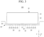
- FIG. 3 shows a front view of a battery cell and a first module case of a battery module according to an embodiment.
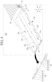
- FIG. 4 shows a perspective view battery cells and a first module case of a battery module according to an embodiment.
- the battery cells 100 may be disposed in a first direction (X) and may be electrically connected to each other.
- the respective battery cells 100 may include various types of known rechargeable batteries that may be repeatedly charged and discharged.
- the respective battery cells 100 may include a lithium ion battery, and without being limited thereto, they may include a lithium polymer battery.
- first direction (X), a second direction (Y), and a third direction (Z) may respectively represent directions traversing each other, the directions traversing each other may represent directions that are vertical to each other, and they are not limited thereto.
- the battery cells 100 may respectively include a vent portion 110, a long side 120, a short side 130, and a terminal 140.
- the vent portion 110 may be disposed on the long side 120 of the battery cell 100, and may be a passage through which inner gas is discharged outside the battery cell 100 if a thermal runaway is generated inside the battery cell 100 because of internal or external factors.
- the vent portion 110 may include various known vent means.
- the vent portions 110 included in the battery cells 100 may be disposed in the first direction (X), and the respective vent portions 110 may be disposed on the long sides 120 of the battery cells 100.
- the long side 120 may be a surface that is longer than the short side 130, and is not limited thereto.
- the short side 130 may be a surface that is shorter than the long side 120, and is not limited thereto.
- the battery cell 100 forms a rectangular shape by the short side 130 and the long side 120, and without being limited thereto, the battery cell according to another embodiment may have various known shapes such as a circle, an oval, or a polygon.
- the terminal 140 may be disposed on the short side 130 of the battery cell 100, and the terminals 140 of the battery cells 100 may be electrically connected to each other by the busbar 900.
- the terminals 140 may be disposed on the respective short sides 130 of the battery cells 100.
- the terminals 140 may have various known terminal structures.
- the first module case 200 may extend in the first direction (X) in which the battery cells 100 are disposed and may support the battery cells 100.
- the first module case 200 may support the long sides 120 of the battery cells 100, and without being limited thereto, it may further include a support means for supporting the short sides 130 of the battery cells 100.
- the first module case 200 may include a first vent flow path 210 and second vent flow paths 220.
- the first vent flow path 210 may directly communicate with the vent portions 110 of the battery cells 100, and may dent and extend in the first direction (X).
- the first vent flow path 210 may dent in the third direction (Z) traversing the first direction (X) and the second direction (Y) and may extend in the first direction (X).
- the second vent flow paths 220 may be spaced from each other with the first vent flow path 210 therebetween in the second direction (Y) traversing the first direction (X).
- the second vent flow paths 220 may extend in the first direction (X) and may support the battery cells 100.
- the second vent flow paths 220 directly communicate with the first vent flow path 210.
- the second vent flow paths 220 may include two second vent flow paths 220, and without being limited thereto, they may include at least three second vent flow paths 220.
- the two second vent flow paths 220 may be spaced from each other in the second direction (Y) with the first vent flow path 210 therebetween and may extend in the first direction (X).
- the respective second vent flow paths 220 may include a first sub flow path 221, a second sub flow path 222, a first cell barrier 223, a second cell barrier 224, and a first cover 225.
- the first sub flow path 221 may directly communicate with the first vent flow path 210 and may extend in the first direction (X).
- the first sub flow path 221 may be disposed between the first vent flow path 210 and the second sub flow path 222 in the second direction (Y).
- the first sub flow path 221 may directly communicate with the first vent flow path 210 and the second sub flow path 222 between the first vent flow path 210 and the second sub flow path 222.
- the second sub flow path 222 may be spaced from the first sub flow path 221 in the second direction (Y) and may extend in the first direction (X).
- the second sub flow path 222 may directly communicate with the first sub flow path 221, and may communicate with the first vent flow path 210 through the first sub flow path 221.
- the first cell barrier 223 may be disposed between the first vent flow path 210 and the first sub flow path 221.
- the first cell barrier 223 may be disposed between the first vent flow path 210 and the first sub flow path 221 and may extend in the first direction (X).
- the first cell barrier 223 may define the shape of the first vent flow path 210, which is not limited thereto.
- the first cell barrier 223 may include first through-holes 223a spaced from each other in the first direction (X).
- the first through-holes 223a may be passages for connecting the first vent flow path 210 and the first sub flow path 221.
- the first through-holes 223a may have various types of openings such as a circle, an oval, or a polygon.
- the first through-holes 223a may not overlap second through-holes 224a in the second direction (Y).
- the second cell barrier 224 may be disposed between the first sub flow path 221 and the second sub flow path 222.
- the second cell barrier 224 may be disposed between the first sub flow path 221 and the second sub flow path 222 and may extend in the first direction (X).
- the second cell barrier 224 may define the shapes of the first sub flow path 221 and the second sub flow path 222, which is not limited thereto.
- the second cell barrier 224 may include second through-holes 224a spaced from each other in the first direction (X).
- the second through-holes 224a are passages for connecting the first sub flow path 221 and the second sub flow path 222.
- the second through-holes 224a may have various types of openings such as a circle, an oval, or a polygon.
- the second through-holes 224a may not overlap the first through-holes 223a in the second direction (Y).
- the first cover 225 covers the first sub flow path 221 and the second sub flow path 222.
- the first cover 225 may extend in the first direction (X) and may cover the first sub flow path 221 and the second sub flow path 222.
- the first cover 225 may support the battery cells 100.
- the first cover 225, the first cell barrier 223, and the second cell barrier 224 may define the first vent flow path 210 and the second vent flow path 220, which is not limited thereto.
- Gas generated by the battery cell 100 in which a thermal runaway is generated from among the battery cells 100 is discharged to the outside of the battery module 1000 through the first vent flow path 210 and the second vent flow path 220 of the first module case 200.
- the battery insulating sheet 300 may be disposed between the battery cells 100 and the first module case 200.
- the battery insulating sheet 300 may be an insulating means between the battery cells 100 and the first module case 200, and is not limited thereto.
- the battery insulating sheet 300 may include sheet through-holes 310 penetrated and formed corresponding to the vent portions 110 of the battery cells 100.
- the sheet through-holes 310 may be spaced from each other in the first direction (X).
- the heat insulating sheet 400 may be disposed between the battery insulating sheet 300 and the first module case 200.
- the heat insulating sheet 400 may be attached to a bottom of the first vent flow path 210.
- the heat insulating sheet 400 may reinforce the first module case 200, and if the gas generated by the battery cell 100 in which a thermal runaway is generated from among the battery cells 100 passes through the first vent flow path 210, the heat insulating sheet 400 may minimize deformation of the first module case 200 by a high heat and a high pressure caused by gas and may minimize deformation of the first vent flow path 210 and the second vent flow path 220.
- the second module case 500 may be combined to the first module case 200 with the battery cells 100 therebetween.
- the second module case 500 may be combined to the first module case 200, the first end plate 700, and the second end plate 800 with the battery cells 100 therebetween so the battery cells 100 are completely covered by the first module case 200, the second module case 500, the first end plate 700, and the second end plate 800.
- the second module case 500 may be combined to the first module case 200, the first end plate 700, and the second end plate 800 by welding, and without being limited thereto, they may be combined to each other by various known combination means.
- the second module case 500 and the first module case 200 may include various types of assembling means assembled with a battery pack including battery modules or a vehicle.
- the heat transmitting sheet 600 may be disposed between the battery cells 100 and the second module case 500.
- the heat transmitting sheet 600 may contact the battery cells 100 and the second module case 500 and may exchange heat with the battery cells 100 and the second module case 500.
- the heat transmitting sheet 600 may increase a cooling effect of the battery cells 100.
- the heat transmitting sheet 600 may include various types of known cooling means.
- FIG. 5 shows a perspective view of a portion on which a first end plate of a battery module according to an embodiment is disposed and another portion on which a second end plate is disposed.
- the first end plate 700 may be combined to the first module case 200 and the second module case 500 with the battery cells 100 therebetween.
- the first end plate 700 may include a first module vent portion 710 for communicating with one of the second vent flow paths 220.
- the first module vent portion 710 may communicate with at least one of the second vent flow paths 220 and may discharge the gas generated by the battery cell 100 in which a thermal runaway is generated and provided through the second vent flow path 220 to the outside of the battery module 1000.
- the first module vent portion 710 may be a passage for communicating with at least one of the second vent flow paths 220 and discharging the gas generated by the battery cell 100 in which a thermal runaway is generated and provided through the second vent flow path 220 to the outside of the battery module 1000, which is not limited thereto.
- the second end plate 800 may be spaced from the first end plate 700 with the battery cells 100 therebetween and may be combined to the first module case 200 and the second module case 500.
- the second end plate 800 may include a second module vent portion 810 for communicating with one of the second vent flow paths 220.
- the second module vent portion 810 may communicate with at least one of the second vent flow paths 220 and may discharge the gas generated by the battery cell 100 in which a thermal runaway is generated and provided through the second vent flow path 220 to the outside of the battery module 1000.
- the second module vent portion 810 may be a passage for communicating with at least one of the second vent flow paths 220 and discharging the gas generated by the battery cell 100 in which a thermal runaway is generated and provided through the second vent flow path 220 to the outside of the battery module 1000, which is not limited thereto.
- one of the first end plate 700 and the second end plate 800 may include a first module vent portion 710 communicating with one of the second vent flow paths 220, and the other thereof may include a second module vent portion 810 communicating with the other of the second vent flow paths 220.
- various known battery management modules may be mounted on at least one of the first end plate 700 and the second end plate 800, and the battery management module may manage the battery cells 100 through the busbar 900.
- the busbar 900 may connect terminals 140 of the battery cells 100.
- the busbar 900 may include a flexible printed circuit board (FPCB) for sensing a state of the busbar, and is not limited thereto.
- FPCB flexible printed circuit board
- the busbar cover 950 may be disposed between the busbar 900 and the second module case 500.
- the busbar cover 950 may cover the busbar 900 and may be an insulating means between the busbar 900 and the second module case 500, and is not limited thereto.
- FIG. 6 shows a perspective view that a thermal runaway is generated to some of the battery cells of a battery module according to an embodiment.
- FIG. 7 shows a path for discharging gas generated by a thermal runaway of a battery cell in a battery module according to an embodiment.
- the gas VG generated by the battery cell 100 in which a thermal runaway is generated from among the battery cells 100 is discharged to the outside of the battery module 1000 through the first vent flow path 210 and the second vent flow path 220 of the first module case 200.
- the gas VG generated by the battery cell 100 in which a thermal runaway is generated may move to the first vent flow path 210 from the vent portion 110 of the battery cell 100.
- the gas VG may then move in the first direction (X), may move in the second direction (Y) through the first through-holes 223a of the first cell barrier 223, and may move to the first sub flow path 221 of the second vent flow path 220.
- the gas VG may then move in the first direction (X), may move in the second direction (Y) through the second through-holes 224a of the second cell barrier 224, and may move to the second sub flow path 222 of the second vent flow path 220.
- the gas VG may then move in the first direction (X) and may be discharged to the outside of the battery module 1000.
- the gas VG generated by the vent portion 110 of the battery cell 100 in which a thermal runaway is generated may pass through the first vent flow path 210 and the first sub flow path 221 and the second sub flow path 222 of the second vent flow path 220, and as the first through-holes 223a do not overlap the second through-holes 224a in the second direction (Y), the gas VG is cooled by the first cell barrier 223 and the second cell barrier 224, particles PA included in the gas VG are attached to the first cell barrier 223 and the second cell barrier 224 and are trapped to the first cell barrier 223 and the second cell barrier 224 so the particles PA are separated from the gas VG.
- the gas VG generated by the vent portion 110 of the battery cell 100 in which a thermal runaway is generated may be easily cooled passing through the first vent flow path 210 and the second vent flow path 220 of the first module case 200, and the particles PA may be separated and discharged to the outside of the battery module 1000.
- the battery module 1000 for easily discharging the gas VG generated by the vent portion 110 of the battery cell 100 in which a thermal runaway is generated to the outside corresponding to the thermal runaway of the battery cells 100 to the outside and trapping the particles PA included in the gas VG is provided.
- first module case 200, the second module case 500, the first end plate 700, and the second end plate 800 are combined to each other while completely covering the battery cells 100, the battery module for easily conveying the battery cells, assembling the same, and protecting the same from external impacts is provided.
- a battery module according to another embodiment will now be described with reference to FIG. 8 and FIG. 9 .
- the battery module according to another embodiment that is different from the battery module according to an embodiment will now be described.
- FIG. 8 shows a front view of a battery cell and a first module case of a battery module according to another embodiment.
- FIG. 9 shows a perspective view of battery cells and a first module case of a battery module according to another embodiment.
- the battery module 1002 may include battery cells 100 and a first module case 200.
- the battery module 1002 may further include the battery insulating sheet, the heat insulating sheet, the second module case, the heat transmitting sheet, the first end plate, the second end plate, the busbar, and the busbar cover described according to an embodiment.
- the first module case 200 may include a first vent flow path 210 and second vent flow paths 230.
- the first vent flow path 210 may directly communicate with the vent portions 110 of the battery cells 100, and may dent and extend in the first direction (X).
- the first vent flow path 210 may dent in the third direction (Z) traversing the first direction (X) and the second direction (Y) and may extend in the first direction (X).
- the second vent flow paths 230 may be spaced from each other in the second direction (Y) traversing the first direction (X) with the first vent flow path 210 therebetween.
- the second vent flow paths 230 may extend in the first direction (X) and may support the battery cells 100.
- the second vent flow paths 230 may directly communicate with the first vent flow path 210.
- the second vent flow paths 230 may include two second vent flow paths 230, and without being limited thereto, they may include at least three second vent flow paths 230.
- the two second vent flow paths 230 may be spaced from each other in the second direction (Y) with the first vent flow path 210 therebetween and may extend in the first direction (X).
- the respective second vent flow paths 230 may include a gas flow path 231, a cooling flow path 232, a third cell barrier 233, a barrier 234, and a second cover 235.
- the gas flow path 231 may directly communicate with the first vent flow path 210 and may extend in the first direction (X).
- the gas flow path 231 neighbors the first vent flow path 210 in the second direction (Y).
- the gas flow path 231 may neighbor the cooling flow path 232 in the third direction (Z) traversing the first direction (X) and the second direction (Y) and may directly communicate with the first vent flow path 210.
- the cooling flow path 232 may be spaced from the gas flow path 231 in the third direction (Z) and may extend in the first direction (X).
- the cooling flow path 232 may not communicate with the gas flow path 231 and the first vent flow path 210 and may be separated from the gas flow path 231 and the first vent flow path 210.
- the cooling flow path 232 may be disposed between the gas flow path 231 and the battery cells 100.
- Various types of cooling means such as cooling water may be applied to the cooling flow path 232.
- the third cell barrier 233 may be disposed between the first vent flow path 210 and the gas flow path 231.
- the third cell barrier 233 may be disposed between the first vent flow path 210 and the gas flow path 231 and may extend in the first direction (X).
- the third cell barrier 233 may define the shape of the first vent flow path 210, and is not limited thereto.
- the third cell barrier 233 may include third through-holes 233a spaced from each other in the first direction (X).
- the third through-holes 233a may be a passage for connecting the first vent flow path 210 and the gas flow path 231.
- the third through-holes 233a may have various types of openings such as a circle, an oval, or a polygon.
- the barrier 234 may be disposed between the gas flow path 231 and the cooling flow path 232.
- the barrier 234 may be disposed between the gas flow path 231 and the cooling flow path 232 and may extend in the first direction (X).
- the barrier 234 may define the shapes of the gas flow path 231 and the cooling flow path 232, which is not limited thereto.
- the barrier 234 intercepts the gas flow path 231 and the cooling flow path 232 separated from each other in the third direction (Z).
- the second cover 235 may cover the cooling flow path 232.
- the second cover 235 may extend in the first direction (X) and may cover the cooling flow path 232.
- the second cover 235 may support the battery cells 100.
- the second cover 235, the third cell barrier 233, and the barrier 234 may define the shapes of the first vent flow path 210 and the second vent flow path 230, which is not limited thereto.
- the gas generated by the battery cell 100 in which a thermal runaway is generated from among the battery cells 100 is discharged to the outside of the battery module 1002 through the first vent flow path 210 and the second vent flow path 230 of the first module case 200.
- the gas generated by the battery cell 100 in which a thermal runaway is generated moves to the first vent flow path 210 from the vent portion 110 of the battery cell 100.
- the gas may then move in the first direction (X), may move in the second direction (Y) through the third through-holes 233a of the third cell barrier 233, and may move to the gas flow path 231 of the second vent flow path 230.
- the gas may them move in the first direction (X), may be cooled by the cooling flow path 232 separated by the barrier 234, and may be discharged to the outside of the battery module 1002.
- the gas generated by the vent portion 110 of the battery cell 100 in which a thermal runaway is generated may pass through the gas flow path 231 of the first vent flow path 210 and the second vent flow path 230 and may be cooled by the third cell barrier 233 and the cooling flow path 232, and the particles included in the gas may be attached to the third cell barrier 233 and the barrier 234, may be trapped to the third cell barrier 233 and the barrier 234, and may be separated from the gas.
- the gas generated by the vent portion 110 of the battery cell 100 in which a thermal runaway is generated may be easily cooled through the first vent flow path 210 and the second vent flow path 230 of the first module case 200, and the particles may be separated and may be discharged to the outside of the battery module 1002.
- the battery module 1002 for easily discharging the gas generated by the vent portion 110 of the battery cell 100 in which a thermal runaway is generated to the outside corresponding to the thermal runaway of the battery cells 100 and trapping the particles included in the gas may be provided.
Landscapes
- Chemical & Material Sciences (AREA)
- Chemical Kinetics & Catalysis (AREA)
- Electrochemistry (AREA)
- General Chemical & Material Sciences (AREA)
- Engineering & Computer Science (AREA)
- Manufacturing & Machinery (AREA)
- Battery Mounting, Suspending (AREA)
- Secondary Cells (AREA)
- Gas Exhaust Devices For Batteries (AREA)
Applications Claiming Priority (1)
| Application Number | Priority Date | Filing Date | Title |
|---|---|---|---|
| KR1020230043191A KR102795117B1 (ko) | 2023-03-31 | 2023-03-31 | 배터리 모듈 |
Publications (2)
| Publication Number | Publication Date |
|---|---|
| EP4439795A2 true EP4439795A2 (de) | 2024-10-02 |
| EP4439795A3 EP4439795A3 (de) | 2025-01-22 |
Family
ID=90038273
Family Applications (1)
| Application Number | Title | Priority Date | Filing Date |
|---|---|---|---|
| EP24158924.1A Pending EP4439795A3 (de) | 2023-03-31 | 2024-02-21 | Batteriemodul |
Country Status (4)
| Country | Link |
|---|---|
| US (1) | US20240332722A1 (de) |
| EP (1) | EP4439795A3 (de) |
| KR (1) | KR102795117B1 (de) |
| CN (1) | CN118738756A (de) |
Cited By (1)
| Publication number | Priority date | Publication date | Assignee | Title |
|---|---|---|---|---|
| EP4425673A4 (de) * | 2022-12-23 | 2025-04-23 | SVOLT Energy Technology Co., Ltd. | Batteriepack und elektrische vorrichtung |
Families Citing this family (1)
| Publication number | Priority date | Publication date | Assignee | Title |
|---|---|---|---|---|
| KR20260048055A (ko) * | 2024-10-02 | 2026-04-09 | 삼성에스디아이 주식회사 | 배터리 모듈 및 그를 포함하는 배터리 팩 |
Family Cites Families (13)
| Publication number | Priority date | Publication date | Assignee | Title |
|---|---|---|---|---|
| JP5466906B2 (ja) | 2009-09-18 | 2014-04-09 | パナソニック株式会社 | 電池モジュール |
| WO2020003800A1 (ja) * | 2018-06-26 | 2020-01-02 | 三洋電機株式会社 | 電源装置及びこれを備える車両 |
| US11735788B2 (en) * | 2019-09-05 | 2023-08-22 | Samsung Sdi Co., Ltd. | Energy storage module including insulation spacers and an extinguisher sheet |
| JP7569481B2 (ja) * | 2020-09-30 | 2024-10-18 | 香港時代新能源科技有限公司 | 電池、装置、電池の製造方法及び製造装置 |
| JP7674361B2 (ja) * | 2020-09-30 | 2025-05-09 | 香港時代新能源科技有限公司 | 電池、装置、電池の製造方法及び製造装置 |
| CN114765296A (zh) * | 2021-01-13 | 2022-07-19 | 福特全球技术公司 | 包括排气通道的电池组 |
| KR20220106534A (ko) * | 2021-01-22 | 2022-07-29 | 주식회사 엘지에너지솔루션 | 전지 모듈 이를 포함하는 전지 팩 |
| KR102819175B1 (ko) * | 2021-06-17 | 2025-06-10 | 주식회사 엘지에너지솔루션 | 배터리 모듈, 그것을 포함하는 배터리 팩, 및 자동차 |
| KR102857913B1 (ko) * | 2021-06-17 | 2025-09-09 | 주식회사 엘지에너지솔루션 | 개선된 벤팅 성능을 갖는 배터리 모듈 |
| KR102844252B1 (ko) * | 2021-07-07 | 2025-08-07 | 주식회사 엘지에너지솔루션 | 전지 모듈 및 이를 포함하는 전지 팩 |
| JP7569484B2 (ja) * | 2021-08-30 | 2024-10-18 | 香港時代新能源科技有限公司 | 電池の筐体、電池、電力消費装置、電池の製造方法及び装置 |
| KR20230108139A (ko) * | 2022-01-10 | 2023-07-18 | 에스케이온 주식회사 | 배터리 모듈 및 이를 구비하는 배터리 팩 |
| WO2023133722A1 (zh) * | 2022-01-12 | 2023-07-20 | 宁德时代新能源科技股份有限公司 | 电池的箱体、电池、用电装置、制备电池的方法和装置 |
-
2023
- 2023-03-31 KR KR1020230043191A patent/KR102795117B1/ko active Active
- 2023-10-17 US US18/381,082 patent/US20240332722A1/en active Pending
-
2024
- 2024-02-21 EP EP24158924.1A patent/EP4439795A3/de active Pending
- 2024-03-29 CN CN202410370735.7A patent/CN118738756A/zh active Pending
Cited By (1)
| Publication number | Priority date | Publication date | Assignee | Title |
|---|---|---|---|---|
| EP4425673A4 (de) * | 2022-12-23 | 2025-04-23 | SVOLT Energy Technology Co., Ltd. | Batteriepack und elektrische vorrichtung |
Also Published As
| Publication number | Publication date |
|---|---|
| US20240332722A1 (en) | 2024-10-03 |
| KR20240147347A (ko) | 2024-10-08 |
| CN118738756A (zh) | 2024-10-01 |
| KR102795117B1 (ko) | 2025-04-10 |
| EP4439795A3 (de) | 2025-01-22 |
Similar Documents
| Publication | Publication Date | Title |
|---|---|---|
| CN116349081B (zh) | 电池单体组件以及包括该电池单体组件的电池组和车辆 | |
| US7794875B2 (en) | Battery module | |
| US9640790B2 (en) | Middle or large-sized battery module | |
| US7927728B2 (en) | Battery module interface | |
| EP1992026B1 (de) | Batteriemodul | |
| EP4439795A2 (de) | Batteriemodul | |
| US7794871B2 (en) | Secondary battery and secondary battery module with the same | |
| CN101517782B (zh) | 用于电连接电池组电池的连接构件 | |
| US8968901B2 (en) | Middle or large-sized battery module | |
| CN114303277B (zh) | 电池模块和包括该电池模块的电池组 | |
| US8765287B2 (en) | Battery module | |
| CN114365341B (zh) | 电池模块和包括该电池模块的电池组 | |
| CN114270619A (zh) | 电池模块和包括该电池模块的电池组 | |
| US12542312B2 (en) | Eco-friendly power source such as a battery module for a transportation vehicle | |
| US20240145851A1 (en) | Battery assembly having improved safety | |
| CN118213659A (zh) | 电池模块及包括电池模块的电池组 | |
| KR20230098002A (ko) | 안전성이 강화된 배터리 어셈블리 | |
| KR102887874B1 (ko) | 냉각 장치 및 이를 포함하는 전지 셀 적층체 | |
| KR20240078828A (ko) | 배터리 팩 | |
| KR20260048055A (ko) | 배터리 모듈 및 그를 포함하는 배터리 팩 | |
| KR20250122815A (ko) | 실링 어셈블리를 포함하는 배터리 모듈 | |
| CN121885897A (zh) | 电池模组 | |
| CN117063341A (zh) | 具有加强的安全性的电池组件 | |
| KR20250164460A (ko) | 배터리모듈, 이를 포함하는 배터리팩 및 상기 배터리팩의 조립방법 | |
| CN119278537A (zh) | 具有优异抗冲击性的电池组 |
Legal Events
| Date | Code | Title | Description |
|---|---|---|---|
| PUAI | Public reference made under article 153(3) epc to a published international application that has entered the european phase |
Free format text: ORIGINAL CODE: 0009012 |
|
| STAA | Information on the status of an ep patent application or granted ep patent |
Free format text: STATUS: REQUEST FOR EXAMINATION WAS MADE |
|
| 17P | Request for examination filed |
Effective date: 20240221 |
|
| AK | Designated contracting states |
Kind code of ref document: A2 Designated state(s): AL AT BE BG CH CY CZ DE DK EE ES FI FR GB GR HR HU IE IS IT LI LT LU LV MC ME MK MT NL NO PL PT RO RS SE SI SK SM TR |
|
| PUAL | Search report despatched |
Free format text: ORIGINAL CODE: 0009013 |
|
| AK | Designated contracting states |
Kind code of ref document: A3 Designated state(s): AL AT BE BG CH CY CZ DE DK EE ES FI FR GB GR HR HU IE IS IT LI LT LU LV MC ME MK MT NL NO PL PT RO RS SE SI SK SM TR |
|
| RIC1 | Information provided on ipc code assigned before grant |
Ipc: H01M 50/367 20210101ALI20241216BHEP Ipc: H01M 50/358 20210101ALI20241216BHEP Ipc: H01M 50/291 20210101ALI20241216BHEP Ipc: H01M 50/211 20210101ALI20241216BHEP Ipc: H01M 10/6566 20140101ALI20241216BHEP Ipc: H01M 10/647 20140101ALI20241216BHEP Ipc: H01M 10/613 20140101AFI20241216BHEP |