EP4439788A2 - Batteriepack - Google Patents
Batteriepack Download PDFInfo
- Publication number
- EP4439788A2 EP4439788A2 EP24166287.3A EP24166287A EP4439788A2 EP 4439788 A2 EP4439788 A2 EP 4439788A2 EP 24166287 A EP24166287 A EP 24166287A EP 4439788 A2 EP4439788 A2 EP 4439788A2
- Authority
- EP
- European Patent Office
- Prior art keywords
- battery cells
- battery
- conductive line
- battery pack
- cell
- Prior art date
- Legal status (The legal status is an assumption and is not a legal conclusion. Google has not performed a legal analysis and makes no representation as to the accuracy of the status listed.)
- Granted
Links
Images


Classifications
-
- H—ELECTRICITY
- H01—ELECTRIC ELEMENTS
- H01M—PROCESSES OR MEANS, e.g. BATTERIES, FOR THE DIRECT CONVERSION OF CHEMICAL ENERGY INTO ELECTRICAL ENERGY
- H01M50/00—Constructional details or processes of manufacture of the non-active parts of electrochemical cells other than fuel cells, e.g. hybrid cells
- H01M50/50—Current conducting connections for cells or batteries
- H01M50/569—Constructional details of current conducting connections for detecting conditions inside cells or batteries, e.g. details of voltage sensing terminals
-
- H—ELECTRICITY
- H01—ELECTRIC ELEMENTS
- H01M—PROCESSES OR MEANS, e.g. BATTERIES, FOR THE DIRECT CONVERSION OF CHEMICAL ENERGY INTO ELECTRICAL ENERGY
- H01M10/00—Secondary cells; Manufacture thereof
- H01M10/42—Methods or arrangements for servicing or maintenance of secondary cells or secondary half-cells
- H01M10/425—Structural combination with electronic components, e.g. electronic circuits integrated to the outside of the casing
-
- H—ELECTRICITY
- H01—ELECTRIC ELEMENTS
- H01M—PROCESSES OR MEANS, e.g. BATTERIES, FOR THE DIRECT CONVERSION OF CHEMICAL ENERGY INTO ELECTRICAL ENERGY
- H01M10/00—Secondary cells; Manufacture thereof
- H01M10/42—Methods or arrangements for servicing or maintenance of secondary cells or secondary half-cells
- H01M10/48—Accumulators combined with arrangements for measuring, testing or indicating the condition of cells, e.g. the level or density of the electrolyte
- H01M10/482—Accumulators combined with arrangements for measuring, testing or indicating the condition of cells, e.g. the level or density of the electrolyte for several batteries or cells simultaneously or sequentially
-
- H—ELECTRICITY
- H01—ELECTRIC ELEMENTS
- H01M—PROCESSES OR MEANS, e.g. BATTERIES, FOR THE DIRECT CONVERSION OF CHEMICAL ENERGY INTO ELECTRICAL ENERGY
- H01M10/00—Secondary cells; Manufacture thereof
- H01M10/42—Methods or arrangements for servicing or maintenance of secondary cells or secondary half-cells
- H01M10/48—Accumulators combined with arrangements for measuring, testing or indicating the condition of cells, e.g. the level or density of the electrolyte
- H01M10/486—Accumulators combined with arrangements for measuring, testing or indicating the condition of cells, e.g. the level or density of the electrolyte for measuring temperature
-
- H—ELECTRICITY
- H01—ELECTRIC ELEMENTS
- H01M—PROCESSES OR MEANS, e.g. BATTERIES, FOR THE DIRECT CONVERSION OF CHEMICAL ENERGY INTO ELECTRICAL ENERGY
- H01M50/00—Constructional details or processes of manufacture of the non-active parts of electrochemical cells other than fuel cells, e.g. hybrid cells
- H01M50/20—Mountings; Secondary casings or frames; Racks, modules or packs; Suspension devices; Shock absorbers; Transport or carrying devices; Holders
- H01M50/204—Racks, modules or packs for multiple batteries or multiple cells
- H01M50/207—Racks, modules or packs for multiple batteries or multiple cells characterised by their shape
- H01M50/213—Racks, modules or packs for multiple batteries or multiple cells characterised by their shape adapted for cells having curved cross-section, e.g. round or elliptic
-
- H—ELECTRICITY
- H01—ELECTRIC ELEMENTS
- H01M—PROCESSES OR MEANS, e.g. BATTERIES, FOR THE DIRECT CONVERSION OF CHEMICAL ENERGY INTO ELECTRICAL ENERGY
- H01M50/00—Constructional details or processes of manufacture of the non-active parts of electrochemical cells other than fuel cells, e.g. hybrid cells
- H01M50/20—Mountings; Secondary casings or frames; Racks, modules or packs; Suspension devices; Shock absorbers; Transport or carrying devices; Holders
- H01M50/249—Mountings; Secondary casings or frames; Racks, modules or packs; Suspension devices; Shock absorbers; Transport or carrying devices; Holders specially adapted for aircraft or vehicles, e.g. cars or trains
-
- H—ELECTRICITY
- H01—ELECTRIC ELEMENTS
- H01M—PROCESSES OR MEANS, e.g. BATTERIES, FOR THE DIRECT CONVERSION OF CHEMICAL ENERGY INTO ELECTRICAL ENERGY
- H01M50/00—Constructional details or processes of manufacture of the non-active parts of electrochemical cells other than fuel cells, e.g. hybrid cells
- H01M50/50—Current conducting connections for cells or batteries
- H01M50/502—Interconnectors for connecting terminals of adjacent batteries; Interconnectors for connecting cells outside a battery casing
- H01M50/503—Interconnectors for connecting terminals of adjacent batteries; Interconnectors for connecting cells outside a battery casing characterised by the shape of the interconnectors
-
- H—ELECTRICITY
- H01—ELECTRIC ELEMENTS
- H01M—PROCESSES OR MEANS, e.g. BATTERIES, FOR THE DIRECT CONVERSION OF CHEMICAL ENERGY INTO ELECTRICAL ENERGY
- H01M50/00—Constructional details or processes of manufacture of the non-active parts of electrochemical cells other than fuel cells, e.g. hybrid cells
- H01M50/50—Current conducting connections for cells or batteries
- H01M50/502—Interconnectors for connecting terminals of adjacent batteries; Interconnectors for connecting cells outside a battery casing
- H01M50/507—Interconnectors for connecting terminals of adjacent batteries; Interconnectors for connecting cells outside a battery casing comprising an arrangement of two or more busbars within a container structure, e.g. busbar modules
-
- H—ELECTRICITY
- H01—ELECTRIC ELEMENTS
- H01M—PROCESSES OR MEANS, e.g. BATTERIES, FOR THE DIRECT CONVERSION OF CHEMICAL ENERGY INTO ELECTRICAL ENERGY
- H01M50/00—Constructional details or processes of manufacture of the non-active parts of electrochemical cells other than fuel cells, e.g. hybrid cells
- H01M50/50—Current conducting connections for cells or batteries
- H01M50/502—Interconnectors for connecting terminals of adjacent batteries; Interconnectors for connecting cells outside a battery casing
- H01M50/509—Interconnectors for connecting terminals of adjacent batteries; Interconnectors for connecting cells outside a battery casing characterised by the type of connection, e.g. mixed connections
-
- H—ELECTRICITY
- H01—ELECTRIC ELEMENTS
- H01M—PROCESSES OR MEANS, e.g. BATTERIES, FOR THE DIRECT CONVERSION OF CHEMICAL ENERGY INTO ELECTRICAL ENERGY
- H01M50/00—Constructional details or processes of manufacture of the non-active parts of electrochemical cells other than fuel cells, e.g. hybrid cells
- H01M50/50—Current conducting connections for cells or batteries
- H01M50/502—Interconnectors for connecting terminals of adjacent batteries; Interconnectors for connecting cells outside a battery casing
- H01M50/519—Interconnectors for connecting terminals of adjacent batteries; Interconnectors for connecting cells outside a battery casing comprising printed circuit boards [PCB]
-
- H—ELECTRICITY
- H01—ELECTRIC ELEMENTS
- H01M—PROCESSES OR MEANS, e.g. BATTERIES, FOR THE DIRECT CONVERSION OF CHEMICAL ENERGY INTO ELECTRICAL ENERGY
- H01M10/00—Secondary cells; Manufacture thereof
- H01M10/42—Methods or arrangements for servicing or maintenance of secondary cells or secondary half-cells
- H01M10/425—Structural combination with electronic components, e.g. electronic circuits integrated to the outside of the casing
- H01M2010/4271—Battery management systems including electronic circuits, e.g. control of current or voltage to keep battery in healthy state, cell balancing
-
- Y—GENERAL TAGGING OF NEW TECHNOLOGICAL DEVELOPMENTS; GENERAL TAGGING OF CROSS-SECTIONAL TECHNOLOGIES SPANNING OVER SEVERAL SECTIONS OF THE IPC; TECHNICAL SUBJECTS COVERED BY FORMER USPC CROSS-REFERENCE ART COLLECTIONS [XRACs] AND DIGESTS
- Y02—TECHNOLOGIES OR APPLICATIONS FOR MITIGATION OR ADAPTATION AGAINST CLIMATE CHANGE
- Y02E—REDUCTION OF GREENHOUSE GAS [GHG] EMISSIONS, RELATED TO ENERGY GENERATION, TRANSMISSION OR DISTRIBUTION
- Y02E60/00—Enabling technologies; Technologies with a potential or indirect contribution to GHG emissions mitigation
- Y02E60/10—Energy storage using batteries
Definitions
- Embodiments relate to a battery pack.
- a secondary battery refers to a chargeable and dischargeable battery, unlike a primary battery that is not chargeable. Secondary batteries are used as energy sources for mobile devices, electric vehicles, hybrid vehicles, electric bicycles, uninterruptible power supplies, etc. According to a type of an external device they are applied to, secondary batteries may be used in the form of a single battery or in the form of a pack in which multiple battery cells are connected and grouped into one unit.
- Small mobile devices such as mobile phones may operate for a certain amount of time based on the output and capacity of a single battery, whereas for devices requiring long-term driving and high-power operations such as electric vehicles, hybrid vehicles, etc., consuming a lot of power, a secondary battery of a module type including a plurality of batteries may be preferred due to output and capacity issues.
- the output voltage or output current may be increased with the number of built-in batteries.
- the present invention is directed to a battery pack in which, by replacing a bus bar electrically connecting a plurality of battery cells to each other with a conductive pattern on a cell holder, the cell holder may be formed integrally with the bus bar and a component for sensing a voltage and a temperature of the battery cell may be replaced with the conductive pattern on the cell holder.
- Embodiments are directed to a battery pack, including a plurality of battery cells in a row in a first direction and in a plurality of rows in a second direction intersecting the first direction, a cell holder in which the plurality of battery cells are assembled at a first side thereof, and a first conductive line of the cell holder plated and patterned at a second side opposite to the first side electrically connecting different battery cells to each other and extending in the second direction.
- the battery pack may further include a second conductive line plated and patterned at the second side of the cell holder to collect state information about different battery cells.
- first conductive line and the second conductive line may be formed on the cell holder through laser direct structuring (LDS).
- LDS laser direct structuring
- the first conductive line may have a greater width than a width of the second conductive line.
- the first conductive line B may be formed as a 1-shape structure.
- the second conductive line may include a voltage sensing line that may be connected to each first conductive line to sense a voltage and a temperature sensing line to sense a temperature at a certain position.
- the plurality of battery cells may be arranged such that battery cells in adjacent rows in the second direction may be alternately staggered with each other at front and rear positions in the first direction.
- the battery cells 10 of any one row may be arranged to be inserted into a valley between the battery cells 10 of the other row.
- the battery cells 10 of any one row may be arranged to be biased relatively toward the front position or the rear position in the first direction Z1, and the battery cells 10 of the other row may be arranged to be biased relatively toward the rear position or the front position in the first direction Z1.
- the first conductive line may include a plurality of first conductive lines electrically connecting the battery cells to each other, and each of the plurality of first conductive lines may extend between a first group of battery cells and a second group of battery cells, the first group of battery cells and the second group of battery cells may be adjacent to each other in the first direction and may be arranged in the second direction.
- first group of battery cells and the second group of battery cells may be arranged in the second direction and may be connected to each other in parallel, and the first group of battery cells and the second group of battery cells may be connected to each other in series in the first direction.
- each of the plurality of first conductive lines may extend in a zigzag pattern and have a curved portion surrounding an outer circumferential surface of an electrode at a center position of the first and second groups of battery cells.
- the battery cell 10 may be arranged to be surrounded by a front curved portion of the first conductive line at the front position and a rear curved portion of the first conductive line at the rear position.
- an end of the second conductive line may be connected to a battery management system, extend in the second direction, and include a plurality of branch lines.
- first and second electrodes at an end of a battery cell may be exposed to outside of the cell holder through first and second electrode holes in the cell holder and may be connected to the first conductive line through a connection member, and a second electrode selectively from the first and second electrodes may be at the other end of the battery cell.
- first may be referred to as a second component without departing from the scope of the present disclosure, and similarly, the second component may be referred to as the first component.
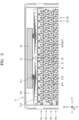
- FIG. 1 shows an exploded perspective view of a battery pack according to embodiments.
- the battery pack may include a plurality of battery cells 10 and a cell holder H.
- Each of the plurality of battery cells 10 may include first electrodes E1 and second electrodes E2 which have different polarities.
- the battery cell 10 may include the electrodes E1 and E2 at opposite end positions in a height direction Z3.
- the battery cell 10 may include a cylindrical battery cell 10 including circumferential side surfaces connecting the electrodes E1 and E2 at the opposite end positions.
- the first electrode E1 and the second electrode E2 may be formed in an upper end of the battery cell 10 in the height direction Z3 of the battery cell 10.
- the first electrode E1 may be formed at a center position of the upper end of the battery cell 10
- the second electrode E2 may be formed at an edge position surrounding the first electrode E1 in the upper end of the battery cell 10.
- the second electrode E2 may extend from the edge position of the upper end of the battery cell 10 to a lower end in the height direction Z3 of the battery cell 10.
- the second electrode E2 may be formed over the entire lower end of the battery cell 10 while forming the side surface between the upper end and the lower end of the battery cell 10.
- the cell holder H may provide a receiving space for the plurality of battery cells 10, and may be modularized into a single pack by physically binding the plurality of battery cells 10 to each other. Modularization of the plurality of battery cells 10 into a single pack may mean structurally binding the plurality of battery cells 10 to each other, like the cell holder H. In addition, modularization of the plurality of battery cells 10 into a single pack may mean electrically binding the plurality of battery cells 10 into the single pack by electrically connecting the plurality of different battery cells 10 as will be described below.
- the cell holder H may modularize the plurality of battery cells 10 into a single pack by structurally binding the plurality of battery cells 10, and regulate assembly positions of the plurality of battery cells 10.
- the cell holder H may include at least one cell holder H where an end position and/or the other end position of the battery cell 10 is assembled.
- the cell holder H may include a first holder and a second holder assembled to face each other with the plurality of battery cells 10 therebetween, and may include the plurality of battery cells 10 assembled at specified positions of the first and second holders.
- the battery pack may comprise a cell holder H in which the plurality of battery cells 10 may be assembled at a first side thereof.
- the cell holder H may correspond to an insulating structure.
- the insulating structure may form at least a part of the cell holder H and may form the entire cell holder H or a part thereof.
- the insulating structure and the cell holder H may mean substantially the same structure, and hereinbelow, the insulating structure may be referred to as the cell holder H for convenience of understanding, but may also form the entire cell holder H or a part thereof.
- FIG. 2 shows a plan view of a battery pack including the battery cell 10 and the cell holder H assembled together, according to embodiments, and FIG. 3 shows a partial enlarged view of FIG. 2 .
- the plurality of battery cells 10 forming the battery pack may be arranged in a first direction Z1 and a second direction Z2 that intersect each other.
- a row of the battery cells 10 may include a group of the battery cells 10 arranged in the first direction Z1
- a column of the battery cells 10 may include a group of the battery cells 10 arranged in the second direction Z2.
- the group of battery cells 10 arranged in the first direction Z1 may be arranged in the first direction Z1 from a front position to a rear position
- the group of battery cells 10 arranged in the second direction Z2 may be arranged in the second direction Z2 from a left position to a right position.
- a row of the battery cells 10 arranged in the first direction Z1 may be arranged as a plurality of rows R1, R2, R3, and R4 in the second direction Z2 intersecting the first direction Z1.
- the battery pack may comprise a plurality of battery cells 10 in a row in a first direction Z1 and in a plurality of rows in a second direction Z2 intersecting the first direction Z1.
- the battery cells 10 of rows that are adjacent to each other in the second direction Z2 may be arranged to be alternately staggered with each other toward the front position or the rear position in the first direction Z1.
- the battery cells 10 of any one row may be arranged to be inserted into a valley between the battery cells 10 of the other row.
- the battery cells 10 of any one row may be arranged to be biased relatively toward the front position (or the rear position) in the first direction Z1
- the battery cells 10 of the other row may be arranged to be biased relatively toward the rear position (or the front position) in the first direction Z1.
- the battery cells 10 of rows adjacent in the second direction Z2 may be arranged to be staggered with each other relatively toward the front position and the rear position, such that the battery cells 10 of the adjacent rows may be arranged at a high density in a relatively small area and a battery pack favorable to compactness may be provided through the relatively dense arrangement of the battery cells 10.
- the battery cells 10 of a group arranged in the second direction Z2 may include the battery cells 10 of rows alternately arranged in the second direction Z2 rather than the battery cells 10 of all rows arranged in the second direction Z2.
- a first group of battery cells G1 arranged in the second direction Z2 may include the battery cells 10 of odd-numbered rows like the battery cells 10 of the first row R1 and the battery cells 10 of the third row R3, and a second group of battery cells G2 arranged in the second direction Z2 may include the battery cells 10 of even-numbered rows like the battery cells 10 of the second row R2 and the battery cells 10 of the fourth row R4.
- the first conductive line B may include a plurality of first conductive lines B electrically connecting the battery cells 10 to each other.
- each of the plurality of first conductive lines B may extend between a first group of battery cells G1 and a second group of battery cells G2, the first group of battery cells G1 and the second group of battery cells G2 may be adjacent to each other in the first direction Z1 and may be arranged in the second direction Z2.
- the battery cell 10 may be arranged such that an end having the first electrode E1 and the second electrode E2 formed therein is oriented toward a top surface side of the cell holder H and the other end having the second electrode E2 formed therein is oriented toward the opposite side.
- the battery cell 10 may be assembled to the cell holder H such that an end position of the battery cell 10 having both the first electrode E1 and the second electrode E2 formed therein is oriented toward a side of the cell holder H where a first conductive line B described below is arranged.
- a battery pack may include the first conductive line B on the cell holder H.
- the first conductive line B may be arranged on a plane of the cell holder H to electrically connect the plurality of battery cells 10 arranged on the cell holder H.
- the first conductive line B may function as a bus bar that electrically connects the plurality of battery cells 10 to one another.
- the first conductive line B may be arranged on an opposite surface to the plurality of battery cells 10 on the cell holder H.
- the first conductive line B may be arranged on the other side (i.e., an upper surface HU of the cell holder H) opposite to a side where the plurality of battery cells 10 are arranged (i.e., a lower surface HL (refer to FIG. 1 ) of the cell holder H), in the cell holder H.
- the first conductive line B may be formed by being plated and patterned on the cell holder H.
- the battery pack may comprise a first conductive line B of the cell holder H plated and patterned at a second side opposite to the first side electrically connecting different battery cells 10 to each other and extending in the second direction Z2.
- the first conductive line B may be formed on the cell holder H through laser direct structuring (LDS).
- LDS may be a method of selectively processing a pattern by using a laser on a thermoplastic resin such as a plastic injection mold and forming a conductive material through a plating process.
- a pattern for functioning as a bus bar on a plane of the cell holder H may be formed and plated through LSD, thereby forming the first conductive line B.
- the battery pack including the first conductive line B formed by being directly plated and patterned on the plane of the cell holder H may simplify an assembling process between the cell holder H and the bus bar.
- the battery pack including the first conductive line B formed by being directly plated and patterned on the plane of the cell holder H may prevent deformation from occurring due to a difference in a shrinkage rate between metal and plastic.
- FIG. 4 shows a partial enlarged view of FIG. 3 , of an arrangement of the battery cell 10 and the first conductive line B.
- the first conductive line B may be arranged to extend on a plane of the cell holder H in the second direction Z2.
- the first conductive line B may include a plurality of first conductive lines B that electrically connect the plurality of battery cells 10 on the upper surface HU of the cell holder H.
- Each first conductive line B may extend between a group of battery cells 10 (the first group of battery cells G1) arranged in the second direction Z2 and another group of battery cells 10 (the second group of battery cells G2) arranged in the second direction Z2.
- the first conductive line B may extend in a zigzag pattern between the first group of battery cells G1 and the second group of battery cells G2 in the second direction Z2.
- the first conductive line B may extend between the first group of battery cells G1 and the second group of battery cells G2, which are adjacent to each other, in the first direction Z1, and may extend in a zigzag direction while forming a curved portion BC surrounding outer circumferential surfaces of the adjacent groups of battery cells 10 in the first direction Z1.
- each first conductive line B the outer circumferential surfaces of the first group of battery cells G1 and the outer circumferential surfaces of the second group of battery cells G2, surrounded by any one first conductive line B, may be formed on opposite positions.
- the outer circumferential surface of the first group of battery cell G1 surrounded by any one first conductive line B may mean an outer circumferential surface at a rear position 10R in the first direction Z1
- the outer circumferential surface of the second group of battery cell G2 surrounded by the first conductive line B may mean an outer circumferential surface at a front position 10F in the first direction Z1.
- any one first conductive line B surrounds the opposite outer circumferential surfaces of the first and second groups of battery cells G1 and G2, it may mean that the first conductive line B surrounds the outer circumferential surface at a rear position 10R of the battery cell G1 of the first group at the rear position or the outer circumferential surface at a front position 10F of the battery cell G1 of the first group at the front position and surrounds the outer circumferential surface at a front position 10F of the battery cell G2 of the second group at the front position or the outer circumferential surface at a rear position 10R of the battery cell G2 of the second group at the rear position.
- the battery cell 10 may be arranged to be surrounded by a front curved portion BCF of the first conductive line B at the front position and a rear curved portion BCR of the first conductive line B at the rear position.
- the first conductive line B surrounds the outer circumferential surface of the battery cell 10, it may include a case where the first conductive line B surrounds an outer circumferential surface of the first electrode E1 formed at the center position of the battery cell 10 while extending across the outer circumferential surface of the battery cell 10.
- the curved portion BC of the first conductive line B may surround the outer circumferential surface of the battery cell 10 or the outer circumferential surface of the first electrode E1 formed at the center position of the battery cell 10.
- the curved portion BC of the first conductive line B may surround the outer circumferential surface of the first electrode E1 formed at the center position of the battery cell 10 while extending across the second electrode E2 formed at an edge position of the battery cell 10 to surround the first electrode E1.
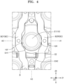
- FIG. 5 shows a connection state between the battery cell 10 and the first conductive line B according to embodiments.
- the first conductive line B may be electrically connected to the battery cell 10 via a connection member C between different first electrodes E1 and second electrodes E2 of the battery cell 10.
- the connection member C may include a conductive wire as a conductive member.
- connection member C may be connected to the first conductive line B at an end position and to the battery cell 10 at the other end position.
- the first conductive line B may be electrically connected to the first electrode E1 of the battery cell 10 through the connection member C extending between the first electrode E1 of the battery cell 10 and the first conductive line B and may be electrically connected to the second electrode E2 of the battery cell 10 through the connection member C extending between the second electrode E2 of the battery cell 10 and the first conductive line B.
- the first electrode E1 may be formed at the center position of the battery cell 10 at an end of the battery cell 10, and the second electrode E2 may be formed at an edge position surrounding the center position of the battery cell 10.
- the first electrode E1 and the second electrode E2 formed at the end position of the battery cell 10 may be exposed from the cell holder H through a first electrode hole EH1 and a second electrode hole EH2 of the cell holder H where the first conductive line B is arranged, and may be connected to the first conductive line B through the connection member C.
- the plurality of battery cells 10 may be electrically connected to each other by the first conductive line B.
- the first conductive line B may connect different battery cells 10 in parallel by connecting the same polarities of the different battery cells 10 or may connect different battery cells 10 in series by connecting different polarities of the different battery cells 10.
- the first conductive line B may connect different battery cells 10 in parallel by connecting the same polarities of the different battery cells 10 through the connection member C. In an implementation, the first conductive line B may connect the different battery cells 10 in parallel by connecting the first electrodes E1 or the second electrodes E2 of the different battery cells 10. Similarly, the first conductive line B may connect the different battery cells 10 in series by connecting the different polarities of the different battery cells 10 through the connection member C. In an implementation, the first conductive line B may connect the different battery cells 10 in series by connecting the first electrodes E1 of the different battery cells 10 to the second electrodes E2 of the different battery cells 10.
- the plurality of battery cells 10 included in the battery pack may be electrically connected to each other such that they are connected in parallel in the second direction Z2 and in series in the first direction Z1.
- the first electrode E1 or the second electrode E2 may be connected to the first conductive line B in each battery cell 10 of the first group of battery cells G1 and the second electrode E2 or the first electrode E1 may be connected to the first conductive line B in each battery cell 10 of the second group of battery cells G2.
- first conductive line B in the first group of battery cells G1 located at the front, the first conductive line B and the first electrode E1 may be connected through the connection member C, and in the second group of battery cells G2 located at the rear, the first conductive line B and the second electrode E2 may be connected through the connection member C, such that the battery cells G1 and G2 may be connected in parallel in the second direction Z2 and in series in the first direction Z1.
- the first conductive line B may be formed as a 1-shape structure.
- the first conductive line B may be formed as a 1 -shape structure extending in a zigzag pattern in the second direction Z2.
- a lower current may flow through the bus bar of the 1-shape structure, reducing the amount of heat emission, and the bus bar of the 1-shape structure may be implemented as a thinner bus bar.
- the first conductive line B of the 1-shape structure may be formed in the cell holder H through LDS, thus functioning as a bus bar.
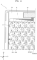
- FIG. 6 shows a partial enlarged view of the cell holder H where the first conductive line B and a voltage sensing line VL are plated and patterned, according to embodiments
- FIG. 7 shows a partial enlarged view of the cell holder H where a temperature sensing line TL is plated and patterned, according to embodiments.
- the battery pack may include a battery management system (BMS) 20 and a second conductive line that gathers state information about the plurality of battery cells 10 to transmit the state information to the BMS 20.
- the BMS 20 may monitor current, voltage, temperature, etc., of the battery cell 10, which are measured through a sensor, to predict a charge state and a lifetime of the battery cell 10, and perform a control operation to avoid over-charge, over-discharge, and over-current of a battery.
- the second conductive line may include a voltage sensing line VL for measuring a bank voltage of each battery cell 10 and a temperature sensing line TL for measuring a temperature of the battery cell 10.
- the second conductive line may include a voltage sensing line VL that may be connected to the first conductive line B to sense a voltage and a temperature sensing line TL to sense a temperature at a certain position.
- the BMS 20 and the second conductive line may be arranged on the cell holder H.
- the BMS 20 may be arranged at a side in the second direction Z2 on the cell holder H, e.g., at a side on a top surface of the cell holder H where an end of the first conductive line B is arranged.
- the BMS 20 is shown as being arranged on the top surface of the cell holder H where the first conductive line B and the second conductive line are arranged, but the BMS 20 may also be arranged at a side including a side surface of the cell holder H and connected to the second conductive line.
- an end of the second conductive line may be connected to the battery management system BMS, may extend in the second direction Z2, and may include a plurality of branch lines.
- the voltage sensing line VL may sense a voltage of the battery cell 10 and transmit the same to the BMS 20.
- the voltage sensing line VL may include a plurality of voltage sensing lines VL for connection to each first conductive line B.
- the voltage sensing line VL may include a main line VL1 connected to the BMS 20 and a branch line VL2 connected to each first conductive line B.
- one end of the main line VL1 of the voltage sensing line VL may be connected to the BMS 20 to extend in the second direction Z2, and the other end thereof may be connected to the branch line VL2 so as to be connected to each first conductive line B.
- Each voltage sensing line VL may connect an end of the first conductive line B to the BMS 20 on the cell holder H to transmit voltage information about the first conductive line B to the BMS 20.
- the temperature sensing line TL may sense the temperature of the battery cell 10 to transmit the same to the BMS 20.
- the temperature sensing line TL may be arranged on the cell holder H and connected to a thermistor TH for detecting the temperature of the battery cell 10 to transmit the temperature of the battery cell 10 to the BMS 20.
- the thermistor TH may be arranged at a certain position of the cell holder H including a central portion to measure the temperature of the battery cell 10, and the temperature sensing line TL may be connected to the thermistor TH to transmit the measured temperature of the battery cell 10 to the BMS 20.
- the thermistors TH may be arranged in series such that two temperature sensing lines TL of an input line and an output line are arranged in a single line in the second direction Z2, or the thermistors TH may be arranged at various positions on the cell holder H and thus the temperature sensing lines TL may include a plurality of branch lines.
- the second conductive line may be formed by being plated and patterned on the cell holder H.
- the voltage sensing line VL and the temperature sensing line TL may be formed on the cell holder H through LDS.
- Some other battery packs may require a separate connection structure for connection to the BMS 20 to measure a voltage and a temperature of the battery cell 10.
- the battery pack including the voltage sensing line VL and the temperature sensing line TL formed by being directly plated and patterned on a plane of the cell holder H may be implemented through LDS without a separate component for connection to the first conductive line B or the BMS 20.
- an aluminum block and a printed circuit board (PCB, or a flexible PCB (FPCB)) for connecting the bus bar to the BMS 20 through wirebonding may be omitted.
- PCB printed circuit board
- FPCB flexible PCB
- the voltage sensing line VL and the temperature sensing line TL may be implemented in a fine pattern on the cell holder H.
- a width of the first conductive line B may be related to a resistance and the amount of heat emission and thus may be large, and the second conductive line may be formed to have a narrow width.
- the battery pack including the voltage sensing line VL and the temperature sensing line TL that are implemented in a fine pattern through LDS may be formed integrally on the cell holder H without a separate connection member, and thus may have a less size of the BMS 20 than the other battery pack, allowing free designing thereof.
- the first conductive line B may have a greater width than a width of the second conductive line.
- the bus bar electrically connecting the plurality of battery cells 10 may be formed as the first conductive line B through LDS, thus providing the battery pack where the cell holder H and the bus bar are integrally formed.
- the battery cells 10 may be connected to the 1-shape first conductive line B such that the number of parallel cells of the module/pack matches arrangement of the actual physical battery cells 10.
- the first conductive line B may be directly formed on the cell holder H through the LDS process, separate attachment component and attachment process may be omitted and deformation may be prevented from occurring due to a difference in a shrinkage rate between metal and plastic.
- the second conductive line for transmitting the state information about the battery, such as a voltage, a temperature, etc., to the BMS 20 may be provided by being formed integrally with the cell holder H.
- the cell holder H, the voltage sensing line VL, and the temperature sensing line TL may be integrally formed, such that a separate connection component may be omitted and the size of the BMS 20 may be implemented as being small, enabling free designing.
- the use of the term "the” and similar indicators thereof may correspond to both the singular and the plural.
- the range includes the disclosure to which an individual value falling within the range is applied (unless stated otherwise), and is the same as the description of an individual value constituting the range in the detailed description of the present disclosure.
- the operations may be performed in an appropriate order.
- the present disclosure is not necessarily limited according to the describing order of the operations.
- the use of all examples or exemplary terms (for example, etc.) in the present disclosure are to simply describe the present disclosure in detail, and unless the range of the present disclosure is not limited by the examples or the exemplary terms unless limited by the claims.
- a battery pack may be provided in which by replacing a bus bar electrically connecting a plurality of battery cells to each other with a conductive pattern on a cell holder, the cell holder formed integrally with the bus bar may be provided and a part for sensing a voltage and a temperature of the battery cell may be replaced with the conductive pattern on the cell holder, thereby simplifying a manufacturing process without a separate connection component.
- small mobile devices such as mobile phones may operate for a certain amount of time based on the output and capacity of a single battery, whereas for devices requiring long-term driving and high-power operations such as electric vehicles, hybrid vehicles, etc., consuming a lot of power, a secondary battery of a module type including a plurality of batteries may be preferred due to output and capacity issues.
- the output voltage or output current may be increased with the number of built-in batteries.
- Embodiments of the present disclosure include a battery pack in which, by replacing a bus bar electrically connecting a plurality of battery cells to each other with a conductive pattern on a cell holder, the cell holder may be formed integrally with the bus bar and a component for sensing a voltage and a temperature of the battery cell may be replaced with the conductive pattern on the cell holder, thereby simplifying a manufacturing process without a separate connection component.
- Example embodiments have been disclosed herein, and although specific terms are employed, they are used and are to be interpreted in a generic and descriptive sense only and not for purpose of limitation.
Landscapes
- Chemical & Material Sciences (AREA)
- Chemical Kinetics & Catalysis (AREA)
- Electrochemistry (AREA)
- General Chemical & Material Sciences (AREA)
- Engineering & Computer Science (AREA)
- Manufacturing & Machinery (AREA)
- Microelectronics & Electronic Packaging (AREA)
- Aviation & Aerospace Engineering (AREA)
- Battery Mounting, Suspending (AREA)
- Connection Of Batteries Or Terminals (AREA)
Applications Claiming Priority (2)
| Application Number | Priority Date | Filing Date | Title |
|---|---|---|---|
| KR20230039404 | 2023-03-26 | ||
| KR1020230089090A KR20240144829A (ko) | 2023-03-26 | 2023-07-10 | 배터리 팩 |
Publications (3)
| Publication Number | Publication Date |
|---|---|
| EP4439788A2 true EP4439788A2 (de) | 2024-10-02 |
| EP4439788A3 EP4439788A3 (de) | 2024-11-06 |
| EP4439788B1 EP4439788B1 (de) | 2025-12-03 |
Family
ID=90482413
Family Applications (1)
| Application Number | Title | Priority Date | Filing Date |
|---|---|---|---|
| EP24166287.3A Active EP4439788B1 (de) | 2023-03-26 | 2024-03-26 | Batteriepack |
Country Status (3)
| Country | Link |
|---|---|
| US (1) | US20240322379A1 (de) |
| EP (1) | EP4439788B1 (de) |
| PL (1) | PL4439788T3 (de) |
Family Cites Families (5)
| Publication number | Priority date | Publication date | Assignee | Title |
|---|---|---|---|---|
| US20140234686A1 (en) * | 2013-02-19 | 2014-08-21 | Faster Faster, Inc. | Thermal Interface and Thermal Management System for Battery Cells |
| US9735414B2 (en) * | 2015-08-11 | 2017-08-15 | Atieva, Inc. | Current distribution system for a battery assembly utilizing non-overlapping bus bars |
| US20190081370A1 (en) * | 2017-09-12 | 2019-03-14 | Sf Motors, Inc. | Embedded current collector for electric vehicle battery monitoring |
| KR102006686B1 (ko) * | 2018-03-07 | 2019-08-02 | 주식회사 이엠따블유 | 배터리 센싱 모듈 및 이의 제조 방법 |
| US12002993B2 (en) * | 2021-09-10 | 2024-06-04 | Milwaukee Electric Tool Corporation | Battery pack with wire bonded bus bars |
-
2023
- 2023-10-27 US US18/384,592 patent/US20240322379A1/en active Pending
-
2024
- 2024-03-26 EP EP24166287.3A patent/EP4439788B1/de active Active
- 2024-03-26 PL PL24166287.3T patent/PL4439788T3/pl unknown
Also Published As
| Publication number | Publication date |
|---|---|
| PL4439788T3 (pl) | 2026-03-23 |
| EP4439788A3 (de) | 2024-11-06 |
| EP4439788B1 (de) | 2025-12-03 |
| US20240322379A1 (en) | 2024-09-26 |
Similar Documents
| Publication | Publication Date | Title |
|---|---|---|
| US10553909B2 (en) | Battery pack | |
| US8080332B2 (en) | Battery pack including cylindrical cells arranged in two rows and two layers | |
| US8080331B2 (en) | Battery pack including eight cylindrical cells in series-parallel configuration | |
| US8614016B2 (en) | Battery pack having enhanced manufacturing efficiency | |
| US8691412B2 (en) | Battery pack | |
| KR102758669B1 (ko) | 배터리 팩 | |
| US9105914B2 (en) | Battery pack including electrode tabs with load absorbing parts | |
| KR102505615B1 (ko) | 배터리 팩 | |
| US20110104521A1 (en) | Battery system and electric vehicle including the same | |
| US20080286642A1 (en) | Battery pack | |
| US11799143B2 (en) | Battery pack | |
| KR102731009B1 (ko) | 배터리 팩 | |
| US8597810B2 (en) | Battery pack | |
| US8604749B2 (en) | Battery pack | |
| US20180159098A1 (en) | Lithium-ion battery pack | |
| US20160322838A1 (en) | Battery pack | |
| US7955727B2 (en) | Battery pack | |
| EP4439788A2 (de) | Batteriepack | |
| KR20140065582A (ko) | 전지팩의 탭 연결장치 | |
| US20220140449A1 (en) | Battery pack | |
| CN118712664A (zh) | 电池组 | |
| KR20240144829A (ko) | 배터리 팩 | |
| US12255358B2 (en) | Battery module | |
| US20250096341A1 (en) | Apparatus for measuring battery temperature | |
| US12176581B2 (en) | Battery pack |
Legal Events
| Date | Code | Title | Description |
|---|---|---|---|
| PUAI | Public reference made under article 153(3) epc to a published international application that has entered the european phase |
Free format text: ORIGINAL CODE: 0009012 |
|
| STAA | Information on the status of an ep patent application or granted ep patent |
Free format text: STATUS: REQUEST FOR EXAMINATION WAS MADE |
|
| 17P | Request for examination filed |
Effective date: 20240326 |
|
| AK | Designated contracting states |
Kind code of ref document: A2 Designated state(s): AL AT BE BG CH CY CZ DE DK EE ES FI FR GB GR HR HU IE IS IT LI LT LU LV MC ME MK MT NL NO PL PT RO RS SE SI SK SM TR |
|
| PUAL | Search report despatched |
Free format text: ORIGINAL CODE: 0009013 |
|
| AK | Designated contracting states |
Kind code of ref document: A3 Designated state(s): AL AT BE BG CH CY CZ DE DK EE ES FI FR GB GR HR HU IE IS IT LI LT LU LV MC ME MK MT NL NO PL PT RO RS SE SI SK SM TR |
|
| RIC1 | Information provided on ipc code assigned before grant |
Ipc: H01M 50/213 20210101ALI20241002BHEP Ipc: H01M 50/569 20210101ALI20241002BHEP Ipc: H01M 50/519 20210101ALI20241002BHEP Ipc: H01M 50/509 20210101ALI20241002BHEP Ipc: H01M 50/507 20210101ALI20241002BHEP Ipc: H01M 50/503 20210101ALI20241002BHEP Ipc: H01M 50/249 20210101ALI20241002BHEP Ipc: H01M 50/204 20210101ALI20241002BHEP Ipc: H01M 10/48 20060101AFI20241002BHEP |
|
| GRAP | Despatch of communication of intention to grant a patent |
Free format text: ORIGINAL CODE: EPIDOSNIGR1 |
|
| STAA | Information on the status of an ep patent application or granted ep patent |
Free format text: STATUS: GRANT OF PATENT IS INTENDED |
|
| INTG | Intention to grant announced |
Effective date: 20250901 |
|
| RIN1 | Information on inventor provided before grant (corrected) |
Inventor name: LEE, JOOYUL |
|
| GRAS | Grant fee paid |
Free format text: ORIGINAL CODE: EPIDOSNIGR3 |
|
| GRAA | (expected) grant |
Free format text: ORIGINAL CODE: 0009210 |
|
| STAA | Information on the status of an ep patent application or granted ep patent |
Free format text: STATUS: THE PATENT HAS BEEN GRANTED |
|
| AK | Designated contracting states |
Kind code of ref document: B1 Designated state(s): AL AT BE BG CH CY CZ DE DK EE ES FI FR GB GR HR HU IE IS IT LI LT LU LV MC ME MK MT NL NO PL PT RO RS SE SI SK SM TR |
|
| REG | Reference to a national code |
Ref country code: CH Ref legal event code: F10 Free format text: ST27 STATUS EVENT CODE: U-0-0-F10-F00 (AS PROVIDED BY THE NATIONAL OFFICE) Effective date: 20251203 Ref country code: GB Ref legal event code: FG4D |
|
| REG | Reference to a national code |
Ref country code: DE Ref legal event code: R096 Ref document number: 602024001475 Country of ref document: DE |
|
| REG | Reference to a national code |
Ref country code: IE Ref legal event code: FG4D |
|
| REG | Reference to a national code |
Ref country code: NL Ref legal event code: MP Effective date: 20251203 |
|
| PG25 | Lapsed in a contracting state [announced via postgrant information from national office to epo] |
Ref country code: ES Free format text: LAPSE BECAUSE OF FAILURE TO SUBMIT A TRANSLATION OF THE DESCRIPTION OR TO PAY THE FEE WITHIN THE PRESCRIBED TIME-LIMIT Effective date: 20251203 |
|
| REG | Reference to a national code |
Ref country code: LT Ref legal event code: MG9D |
|
| PG25 | Lapsed in a contracting state [announced via postgrant information from national office to epo] |
Ref country code: NO Free format text: LAPSE BECAUSE OF FAILURE TO SUBMIT A TRANSLATION OF THE DESCRIPTION OR TO PAY THE FEE WITHIN THE PRESCRIBED TIME-LIMIT Effective date: 20260303 |
|
| PGFP | Annual fee paid to national office [announced via postgrant information from national office to epo] |
Ref country code: DE Payment date: 20260305 Year of fee payment: 3 |
|
| PG25 | Lapsed in a contracting state [announced via postgrant information from national office to epo] |
Ref country code: FI Free format text: LAPSE BECAUSE OF FAILURE TO SUBMIT A TRANSLATION OF THE DESCRIPTION OR TO PAY THE FEE WITHIN THE PRESCRIBED TIME-LIMIT Effective date: 20251203 Ref country code: HR Free format text: LAPSE BECAUSE OF FAILURE TO SUBMIT A TRANSLATION OF THE DESCRIPTION OR TO PAY THE FEE WITHIN THE PRESCRIBED TIME-LIMIT Effective date: 20251203 |
|
| PGFP | Annual fee paid to national office [announced via postgrant information from national office to epo] |
Ref country code: AT Payment date: 20260301 Year of fee payment: 3 |
|
| PGFP | Annual fee paid to national office [announced via postgrant information from national office to epo] |
Ref country code: HU Payment date: 20260330 Year of fee payment: 3 |
|
| PG25 | Lapsed in a contracting state [announced via postgrant information from national office to epo] |
Ref country code: RS Free format text: LAPSE BECAUSE OF FAILURE TO SUBMIT A TRANSLATION OF THE DESCRIPTION OR TO PAY THE FEE WITHIN THE PRESCRIBED TIME-LIMIT Effective date: 20260303 |
|
| PGFP | Annual fee paid to national office [announced via postgrant information from national office to epo] |
Ref country code: FR Payment date: 20260309 Year of fee payment: 3 |