EP4439786A2 - Batteriepack und verfahren zur herstellung des batteriepacks - Google Patents
Batteriepack und verfahren zur herstellung des batteriepacks Download PDFInfo
- Publication number
- EP4439786A2 EP4439786A2 EP24165231.2A EP24165231A EP4439786A2 EP 4439786 A2 EP4439786 A2 EP 4439786A2 EP 24165231 A EP24165231 A EP 24165231A EP 4439786 A2 EP4439786 A2 EP 4439786A2
- Authority
- EP
- European Patent Office
- Prior art keywords
- sensing
- sensing board
- board
- terminals
- displacement
- Prior art date
- Legal status (The legal status is an assumption and is not a legal conclusion. Google has not performed a legal analysis and makes no representation as to the accuracy of the status listed.)
- Pending
Links
Images














Classifications
-
- H—ELECTRICITY
- H01—ELECTRIC ELEMENTS
- H01M—PROCESSES OR MEANS, e.g. BATTERIES, FOR THE DIRECT CONVERSION OF CHEMICAL ENERGY INTO ELECTRICAL ENERGY
- H01M10/00—Secondary cells; Manufacture thereof
- H01M10/42—Methods or arrangements for servicing or maintenance of secondary cells or secondary half-cells
- H01M10/48—Accumulators combined with arrangements for measuring, testing or indicating the condition of cells, e.g. the level or density of the electrolyte
- H01M10/482—Accumulators combined with arrangements for measuring, testing or indicating the condition of cells, e.g. the level or density of the electrolyte for several batteries or cells simultaneously or sequentially
-
- H—ELECTRICITY
- H01—ELECTRIC ELEMENTS
- H01M—PROCESSES OR MEANS, e.g. BATTERIES, FOR THE DIRECT CONVERSION OF CHEMICAL ENERGY INTO ELECTRICAL ENERGY
- H01M50/00—Constructional details or processes of manufacture of the non-active parts of electrochemical cells other than fuel cells, e.g. hybrid cells
- H01M50/50—Current conducting connections for cells or batteries
- H01M50/569—Constructional details of current conducting connections for detecting conditions inside cells or batteries, e.g. details of voltage sensing terminals
-
- G—PHYSICS
- G01—MEASURING; TESTING
- G01R—MEASURING ELECTRIC VARIABLES; MEASURING MAGNETIC VARIABLES
- G01R31/00—Arrangements for testing electric properties; Arrangements for locating electric faults; Arrangements for electrical testing characterised by what is being tested not provided for elsewhere
- G01R31/36—Arrangements for testing, measuring or monitoring the electrical condition of accumulators or electric batteries, e.g. capacity or state of charge [SoC]
- G01R31/364—Battery terminal connectors with integrated measuring arrangements
-
- H—ELECTRICITY
- H01—ELECTRIC ELEMENTS
- H01M—PROCESSES OR MEANS, e.g. BATTERIES, FOR THE DIRECT CONVERSION OF CHEMICAL ENERGY INTO ELECTRICAL ENERGY
- H01M10/00—Secondary cells; Manufacture thereof
- H01M10/42—Methods or arrangements for servicing or maintenance of secondary cells or secondary half-cells
- H01M10/4207—Methods or arrangements for servicing or maintenance of secondary cells or secondary half-cells for several batteries or cells simultaneously or sequentially
-
- H—ELECTRICITY
- H01—ELECTRIC ELEMENTS
- H01M—PROCESSES OR MEANS, e.g. BATTERIES, FOR THE DIRECT CONVERSION OF CHEMICAL ENERGY INTO ELECTRICAL ENERGY
- H01M10/00—Secondary cells; Manufacture thereof
- H01M10/42—Methods or arrangements for servicing or maintenance of secondary cells or secondary half-cells
- H01M10/48—Accumulators combined with arrangements for measuring, testing or indicating the condition of cells, e.g. the level or density of the electrolyte
- H01M10/486—Accumulators combined with arrangements for measuring, testing or indicating the condition of cells, e.g. the level or density of the electrolyte for measuring temperature
-
- H—ELECTRICITY
- H01—ELECTRIC ELEMENTS
- H01M—PROCESSES OR MEANS, e.g. BATTERIES, FOR THE DIRECT CONVERSION OF CHEMICAL ENERGY INTO ELECTRICAL ENERGY
- H01M50/00—Constructional details or processes of manufacture of the non-active parts of electrochemical cells other than fuel cells, e.g. hybrid cells
- H01M50/20—Mountings; Secondary casings or frames; Racks, modules or packs; Suspension devices; Shock absorbers; Transport or carrying devices; Holders
- H01M50/204—Racks, modules or packs for multiple batteries or multiple cells
- H01M50/207—Racks, modules or packs for multiple batteries or multiple cells characterised by their shape
- H01M50/209—Racks, modules or packs for multiple batteries or multiple cells characterised by their shape adapted for prismatic or rectangular cells
-
- H—ELECTRICITY
- H01—ELECTRIC ELEMENTS
- H01M—PROCESSES OR MEANS, e.g. BATTERIES, FOR THE DIRECT CONVERSION OF CHEMICAL ENERGY INTO ELECTRICAL ENERGY
- H01M50/00—Constructional details or processes of manufacture of the non-active parts of electrochemical cells other than fuel cells, e.g. hybrid cells
- H01M50/50—Current conducting connections for cells or batteries
- H01M50/502—Interconnectors for connecting terminals of adjacent batteries; Interconnectors for connecting cells outside a battery casing
- H01M50/503—Interconnectors for connecting terminals of adjacent batteries; Interconnectors for connecting cells outside a battery casing characterised by the shape of the interconnectors
-
- H—ELECTRICITY
- H01—ELECTRIC ELEMENTS
- H01M—PROCESSES OR MEANS, e.g. BATTERIES, FOR THE DIRECT CONVERSION OF CHEMICAL ENERGY INTO ELECTRICAL ENERGY
- H01M50/00—Constructional details or processes of manufacture of the non-active parts of electrochemical cells other than fuel cells, e.g. hybrid cells
- H01M50/50—Current conducting connections for cells or batteries
- H01M50/502—Interconnectors for connecting terminals of adjacent batteries; Interconnectors for connecting cells outside a battery casing
- H01M50/507—Interconnectors for connecting terminals of adjacent batteries; Interconnectors for connecting cells outside a battery casing comprising an arrangement of two or more busbars within a container structure, e.g. busbar modules
-
- H—ELECTRICITY
- H01—ELECTRIC ELEMENTS
- H01M—PROCESSES OR MEANS, e.g. BATTERIES, FOR THE DIRECT CONVERSION OF CHEMICAL ENERGY INTO ELECTRICAL ENERGY
- H01M50/00—Constructional details or processes of manufacture of the non-active parts of electrochemical cells other than fuel cells, e.g. hybrid cells
- H01M50/20—Mountings; Secondary casings or frames; Racks, modules or packs; Suspension devices; Shock absorbers; Transport or carrying devices; Holders
- H01M50/204—Racks, modules or packs for multiple batteries or multiple cells
- H01M50/207—Racks, modules or packs for multiple batteries or multiple cells characterised by their shape
- H01M50/211—Racks, modules or packs for multiple batteries or multiple cells characterised by their shape adapted for pouch cells
-
- Y—GENERAL TAGGING OF NEW TECHNOLOGICAL DEVELOPMENTS; GENERAL TAGGING OF CROSS-SECTIONAL TECHNOLOGIES SPANNING OVER SEVERAL SECTIONS OF THE IPC; TECHNICAL SUBJECTS COVERED BY FORMER USPC CROSS-REFERENCE ART COLLECTIONS [XRACs] AND DIGESTS
- Y02—TECHNOLOGIES OR APPLICATIONS FOR MITIGATION OR ADAPTATION AGAINST CLIMATE CHANGE
- Y02E—REDUCTION OF GREENHOUSE GAS [GHG] EMISSIONS, RELATED TO ENERGY GENERATION, TRANSMISSION OR DISTRIBUTION
- Y02E60/00—Enabling technologies; Technologies with a potential or indirect contribution to GHG emissions mitigation
- Y02E60/10—Energy storage using batteries
Definitions
- aspects of embodiments of the present disclosure relate to a battery pack and a method of manufacturing the battery pack.
- secondary batteries are designed to be rechargeable, different from non-rechargeable primary batteries. Secondary batteries are used as energy sources of devices, such as mobile devices, electric vehicles, hybrid electric vehicles, electric bicycles, and uninterruptible power supplies. According to the type of external devices using the secondary batteries, secondary batteries may be used as (or implemented as) single battery cells or battery packs including a plurality of battery cells connected together as a unit.
- An output voltage or an output current of a battery pack may increase as the number of battery cells included therein increases.
- Embodiments of the present disclosure include a battery pack and a method of manufacturing the battery pack, in which, when a battery cell in the battery pack swells, a sensing board absorbs the displacement that occurs due to the swelling of the battery cell.
- a battery pack includes: a plurality of battery cells; busbars respectively connected to the plurality of battery cells; a holder accommodating the busbars; a sensing board seated on the holder, connected to the busbars, and extending in a wavy manner (i.e. having a wave-shaped geometry) in a first direction; and sensing terminals connecting the busbars to the sensing board and being configured to detect state information about the plurality of battery cells.
- the sensing board have holes in both sides thereof, and the holder includes protrusions respectively inserted into (i.e. located within) the holes. In response to the sensing terminals moving, the holes in the sensing board move with respect to the protrusions to stretch the sensing board.
- Each of the protrusions may include: a protrusion upper portion; and a protrusion connecting portion connecting the protrusion upper portion to the holder.
- Each of the holes may have: a first hole portion having a first hole portion width corresponding to a width of the protrusion upper portion; and a second hole portion having a second hole portion width corresponding to a width of the protrusion connecting portion.
- the protrusion upper portions may extend through the first hole portions, respectively, and the protrusion connecting portions may respectively pass through the first hole portions and/or the second hole portions.
- the battery pack may further include sensing board connecting portions respectively connecting the sensing terminals to the sensing board, and each of the sensing board connecting portions may be connected to a portion of the sensing board in a direction perpendicular to the first direction.
- the sensing board In response to displacement of the sensing terminals in the first direction, the sensing board may be stretched in the first direction to absorb the displacement by up to a first displacement value, and the sensing board connecting portions may be deformed in a direction perpendicular to a connection direction between the sensing board connecting portions and the sensing terminals to absorb the displacement by up to a second displacement value.
- the battery pack may further include sensing board connecting portions respectively connecting the sensing terminals to the sensing board.
- Each of the sensing board connecting portions may be connected to a portion of the sensing board in a direction parallel to the first direction.
- the sensing board In response to displacement of the sensing terminals in the first direction, the sensing board may be stretched in the first direction to absorb the displacement by up to a first displacement value, and the sensing board connecting portions may be deformed in a direction parallel to a connection direction between the sensing board connecting portions and the sensing terminals to absorb the displacement by up to a second displacement value.
- the sensing board may have a first area forming an edge portion of the sensing board and a second area forming an inner edge portion of the sensing board.
- the sensing board may include: a sensing terminal connecting portion at an end of the sensing terminal and electrically connected to the sensing board passes through the first area to be coupled to the second area of the sensing board; a first circuit path formed in the first direction of the sensing board; a second circuit path passing through the first area and electrically connected to the sensing terminal and another sensing terminal; and a third circuit path electrically connected to the sensing terminal connecting portion of the sensing board in the second area.
- the first circuit path, the second circuit path, and the third circuit path may not overlap each other.
- the protrusion upper portions of the protrusions may be respectively coupled to the protrusion connecting portions by a heat stacking method.
- the protrusion upper portions of the protrusions may be caps respectively fitted onto the protrusion connecting portions.
- the protrusion upper portions of the protrusions may respectively include snap-fit portions, and the snap-fit portions may be snap-fit to the sensing board.
- a method of manufacturing a battery pack includes: coupling a wavy sensing board (i.e. a sensing board having a wave geometry) to a holder by inserting protrusions of the holder into holes in the sensing board, respectively; maintaining a free state in which waviness of the sensing board coupled to the protrusions is released (e.g. to a certain extent, or partially released) by a tensile force of the sensing board and no external force is applied to the sensing board (e.g.
- a wavy sensing board i.e. a sensing board having a wave geometry
- the waviness of the sensing board has an amplitude greater than zero and less than a maximum amplitude
- the battery pack may include sensing board connecting portions that connect the sensing terminals to the sensing board, respectively, and are each connected to a portion of the sensing board in a direction perpendicular to a first direction.
- the absorbing, by the sensing board coupled to the sensing terminals, of the displacement of the sensing terminals in response to the sensing terminals being moved while being stretched in accordance with the movements of the sensing terminals may include: in response to displacement of the sensing terminals in the first direction, absorbing, by the sensing board being stretched in the first direction, the displacement by up to a first displacement value; and absorbing, by the sensing board connecting portions being deformed in a direction perpendicular to a connection direction between the sensing board connecting portions and the sensing terminals, the displacement by up to a second displacement value.
- the battery pack may further include sensing board connecting portions that connect the sensing terminals to the sensing board, respectively, and are each connected to a portion of the sensing board in a direction parallel to a first direction.
- the absorbing, by the sensing board coupled to the sensing terminals, of the displacement of the sensing terminals in response to the sensing terminals being moved while being stretched in accordance with the movements of the sensing terminals may include, in response to displacement of the sensing terminals in the first direction: absorbing, by the sensing board being stretched in the first direction, the displacement by up to a first displacement value; and absorbing, by the sensing board connecting portions being deformed in a direction parallel to a connection direction between the sensing board connecting portions and the sensing terminals, the displacement by up to a second displacement value.
- the coupling of the wavy sensing board to the holder by inserting the protrusions of the holder into the holes of the sensing board, respectively may include: inserting protrusion connecting portions of the holder into the holes in the sensing board, respectively; and coupling protrusion upper portions to the protrusion connecting portions coupled to the holes, respectively.
- the expression "at least one of a, b, or c" indicates only a, only b, only c, both a and b, both a and c, both b and c, all of a, b, and c, or variations thereof.
- the terms “use,” “using,” and “used” may be considered synonymous with the terms “utilize,” “utilizing,” and “utilized,” respectively.
- the terms “substantially,” “about,” and similar terms are used as terms of approximation and not as terms of degree, and are intended to account for the inherent variations in measured or calculated values that would be recognized by those of ordinary skill in the art.
- first, second, third, etc. may be used herein to describe various elements, components, regions, layers, and/or sections, these elements, components, regions, layers, and/or sections should not be limited by these terms. These terms are used to distinguish one element, component, region, layer, or section from another element, component, region, layer, or section. Thus, a first element, component, region, layer, or section discussed below could be termed a second element, component, region, layer, or section without departing from the teachings of example embodiments.
- spatially relative terms such as “beneath,” “below,” “lower,” “above,” “upper,” and the like, may be used herein for ease of description to describe one element or feature's relationship to another element(s) or feature(s) as illustrated in the figures. It will be understood that the spatially relative terms are intended to encompass different orientations of the device in use or operation in addition to the orientation depicted in the figures. For example, if the device in the figures is turned over, elements described as “below” or “beneath” other elements or features would then be oriented “above” or “over” the other elements or features. Thus, the term “below” may encompass both an orientation of above and below. The device may be otherwise oriented (rotated 90 degrees or at other orientations), and the spatially relative descriptors used herein should be interpreted accordingly.
- FIGS. 1 , 2A , 2B , 3A , 3B , 4A , and 4B a battery pack according to embodiments of the present disclosure will be described with reference to FIGS. 1 , 2A , 2B , 3A , 3B , 4A , and 4B .
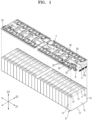
- FIG. 1 is an exploded perspective view of a battery pack according to embodiments of the present disclosure.
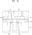
- FIG. 2A is a diagram illustrating a wavy sensing board coupled to protrusions of a holder through insertion according to embodiments of the present disclosure.
- FIG. 2B is a cross-sectional perspective view taken along the line A-A of FIG. 2A .
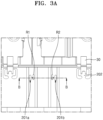
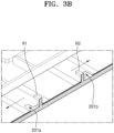
- FIG. 3A is a diagram illustrating a sensing board is stretched to be flat and coupled to protrusions of a holder through insertion according to embodiments of the present disclosure.
- FIG. 3B is a cross-sectional perspective view taken along the line B-B of FIG. 3A .
- FIG. 4A is an enlarged view illustrating protrusion upper portions and protrusion connecting portions according to embodiments of the present disclosure.
- FIG. 4B is a diagram illustrating shapes of hole portions in a sensing board coupled to protrusions shown in FIG. 4A .
- the battery pack may include a plurality of battery cells B arranged in a first direction Z1 and busbars 50 arranged on the plurality of battery cells B to electrically connect different ones of the battery cells B to each other.
- a holder H may be arranged between the busbars 50 and the battery cells B to electrically insulate the busbars 50 from the battery cells B and to align assembly positions of the busbars 50.
- Sensing boards 20 for collecting state information about the battery cells B may be arranged on the holder H along with the busbars 50.
- the busbar 50 may be connected to first and second electrode terminals E1 and E2 of the battery cells B having opposite polarities, which are arranged on a terminal surface 11 of the battery cells B in a second direction Z2 crossing the first direction Z1.
- the first and second electrode terminals E1 and E2 may be arranged in (or may form) first and second rows of electrode terminals E1 and E2 in the first direction Z1, and the busbars 50 electrically connected to the first and second rows of electrode terminals E1 and E2 may be arranged in (or may form) first and second rows of busbars 50 on (or over) the first and second rows of electrode terminals E1 and E2.
- the sensing boards 20 for collecting state information about the plurality of battery cells B may be arranged between the first and second rows of electrode terminals E1 and E2 or between the first and second rows of busbars 50.
- first and second rows of busbars 50 and the sensing boards 20 arranged between the first and second rows of busbars 50 may be supported together on the holder H and may be arranged on the holder H such that their assembly positions are aligned and they may be insulated from the battery cells B.
- the battery cell B may have the terminal surface 11 on which the first and second electrode terminals E1 and E2 are formed, a bottom surface 12 opposite to the terminal surface 11, and side surfaces 13 and 14 connecting (or extending between) the terminal surface 11 and the bottom surface 12.
- the wide side surfaces 13 occupy a relatively large area
- the narrow side surfaces 14 occupy a relatively small area.
- the plurality of battery cells B arranged in the first direction Z1 may be arranged such that the wide side surfaces 13 of different battery cells B face each other.
- a vent 15 for relieving internal pressure in the battery cell B may be formed between the first and second electrode terminals E1 and E2 having opposite polarities on the terminal surface 11 of the battery cell B, and a vent hole V for allowing the flow of exhaust gas discharged through the vent 15 of the battery cell B may be formed in each of the holder H and the sensing board 20 arranged on the vent 15.
- a connector CN electrically connected to the sensing board 20 may be formed at one end of the sensing board 20, and an electrical connection between the sensing board 20 and a battery management unit may be established through the connector CN.
- the busbar 50 may electrically connect different battery cells B to each other, and a plurality of busbars 50 electrically connected to each other may be electrically connected to an external device through input/output terminals 51 and 52.
- the input/output terminals 51 and 52 may include a pair of different input/output terminals 51 and 52 connected to the battery cells B at one end and the other end, respectively, or to the busbars 50 connected to the battery cells B at one end and the other end, respectively.
- the external device to which the plurality of battery cells B are connected through the input/output terminals 51 and 52 may correspond to an external load for receiving discharge power from the battery pack or an external charger for supplying charging power to the battery pack.
- the sensing board 20 is formed having the lengthwise direction in the first direction Z1 and has an edge formed in a direction parallel to the first direction Z1.
- Sensing terminals 30 are connected to an edge portion of the sensing board 20.
- the sensing terminals 30 may collect state information about a plurality of battery cells B.
- the sensing terminals 30 may be connected to the busbars 50 to collect state information about the plurality of battery cells B connected to the busbars 50.
- the sensing terminal 30 may measure state information about the battery cell B, such as temperature, voltage, or current, and for example, the sensing terminal 30 may include a thermistor for measuring a temperature by using a characteristic in which resistance increases or decreases according to the temperature, such as a positive temperature coefficient (PTC) thermistor or a negative temperature coefficient (NTC) thermistor for measuring the temperature of the battery cell B.
- PTC positive temperature coefficient
- NTC negative temperature coefficient
- the battery pack includes the plurality of battery cells B, the holder H accommodating the busbars 50 connected to the plurality of battery cells B, the sensing boards 20 that are seated on the holder H, connected to the busbars 50, and extend in the first direction Z1 to have a wavy shape (i.e. the sensing boards 20 are shaped to have a wave geometry in the first direction Z1), and the sensing terminals 30 that connect the busbars 50 to the sensing boards 20 and detect state information about the plurality of battery cells B.
- the sensing board 20 has holes (e.g., openings) 201a and 201b formed in both sides of the sensing board 20, the holder H includes protrusions R1 and R2 inserted into the holes 201a and 201b, respectively.
- the sensing terminal 30 When the sensing terminal 30 is moved, the positions of the hole portions 201a and 201b in the sensing board 20 are moved with respect to the protrusions R1 and R2 such that the sensing board 20 is stretched.
- the sensing board 20 may be seated on the holder H.
- the sensing board 20 may be formed with the lengthwise direction in the first direction Z1 and to have a wavy shape in the first direction Z1.
- the busbars 50 connecting the plurality of battery cells B to each other and the sensing terminal 30 connected to the busbars 50 may be moved in the direction of the swelling of the battery cells B.
- the plurality of battery cells B are arranged in the first direction Z1 and the areas of the side surfaces 13 of the plurality of battery cells B in the first direction Z1 are larger than the areas of the side surfaces 14 in a second direction Z2, the plurality of battery cells B expand in (e.g., primarily expand in) the first direction Z1 when swelling occurs.
- the busbars 50 and the sensing terminals 30 connected to the plurality of battery cells B may also be moved in the first direction Z1.
- the sensing board 20 extends in the first direction Z1 to have a wavy shape.
- the sensing boards 20 may absorb displacement of the busbars 50 and the sensing terminals 30 by changing the waviness of the sensing boards 20 (e.g. by extending such that the waviness has a lower magnitude).
- the sensing boards 20 may absorb displacement of the busbars 50 and the sensing terminals 30 to absorb changes to the size of the plurality of battery cells B when swelling occurs in the plurality of battery cells B so that the connection between the sensing boards 20 and the plurality of battery cells B, the connection between the plurality of battery cells B and the connector CN through the sensing boards 20, and/or the connection between the plurality of battery cells B and the input/output terminals 51 and 52 through the sensing boards 20 may be stably maintained.
- the sensing board 20 having the wavy shape may absorb displacement of the busbars 50 or the sensing terminals 30 by being deformed from the wavy shape to a flat (or flatter) shape (i.e. a wave with a lower magnitude).
- the maximum value of the displacement absorbed by the sensing board 20 may be a distance by which the sensing terminals 30 coupled to the sensing board 20, which has the wavy shape when an external force is not applied thereto, are moved until the waviness of the sensing board 20 becomes zero (e.g., when the sensing board 20 is completely flat) due to the movement of the sensing terminals 30 coupled to the sensing board 20.
- the direction of the waviness of the sensing board 20 is illustrated and described as being in the first direction Z1 but may also be the second direction Z2 according to the arrangement and arrangement direction of the plurality of battery cells B.
- the interval between waves on the sensing board 20 or the size of the waves may vary.
- the sensing board 20 may be formed of (e.g., the sensing board 20 may be) a flexible printed circuit (FPC) film.
- the wavy sensing board 20 may be easily manufactured by using the FPC film because it is flexible and, thus, easily bendable.
- the protrusions R1 and R2 include protrusion upper portions R11 and R21 and protrusion connecting portions R12 and R22 connecting the protrusion upper portions R11 and R21 to the holder H, respectively (see, e.g., FIG. 4A ).
- the hole portions 201a and 201b include first hole portions 201a1 and 201b1 having a first hole portion width W21 corresponding to the width of the protrusion upper portions R11 and R21 and second hole portions 201a2 and 201b2 having a second hole portion width W22 corresponding to the width of the protrusion connecting portions R12 and R22, respectively (see, e.g., FIG. 4B ).
- the sensing board 20 may be kept wavy (e.g., may be maintained in a wavy state) to a certain extent as illustrated in FIGS. 2A and 2B .
- the sensing board 20 When swelling occurs in the plurality of battery cells B in the state shown in FIGS. 2A and 2B and the positions of the busbars 50 or the sensing terminals 30 are changed, the sensing board 20 may be deformed from the wavy shape shown in FIGS. 2A and 2B to a flat shape shown in FIGS. 3A and 3B to absorb the changes in the positions of the sensing terminals 30 and, thus, absorb a displacement of the sensing terminals 30.
- the protrusion upper portions R11 and R21 are formed to correspond to the first hole portions 201a1 and 201b1, respectively, and the protrusion connecting portions R12 and R22 are formed to correspond to the second hole portions 201a2 and 201b2, respectively.
- a protrusion connecting portion width W12 of the protrusion connecting portions R12 and R22 is less than a protrusion upper portion width W11.
- the protrusion upper portions R11 and R21 are formed to be able to pass through the first hole portions 201a1 and 201b1, respectively, such that the first hole portions 201a1 and 201b1 pass through the protrusion upper portions R11 and R21, respectively, and thus, the sensing board 20 may be coupled to the holder H.
- the second hole portions 201a2 and 201b2 are moved with respect to the protrusion connecting portions R12 and R22, respectively, and because the second hole portion width W22 of the second hole portions 201a2 and 201b2 is less than the protrusion upper portion width W11, the sensing board 20 is only moved while the protrusions R1 and R2 extend therethrough and is unable to escape from (e.g., cannot become disconnected from) the protrusions R1 and R2.
- the second hole portions 201a2 and 201b2 may be moved in first moving directions DIR1 through the protrusion connecting portions R12 and R22 having the protrusion connecting portion width W12 corresponding to the second hole portion width W22.
- Each of the second hole portions 201a2 and 201b2 is moved only in a direction to get closer to or to move away from each other.
- the waviness of the sensing board 20 may increase (or may become larger).
- the waviness of the sensing board 20 may decrease (or may become smaller).
- the description of the illustrated embodiment has focused on the movement of the second hole portions 201a2 and 201b2 in the sensing board 20 in only the first moving directions DIR1 parallel to the first direction Z1, but the second hole portions 201a2 and 201b2 may also be moved with respect to the protrusion connecting portions R12 and R22 in second moving directions DIR2 perpendicular to the first moving directions DIR1 and, thus, may absorb swelling of the plurality of battery cells B in other directions as well.
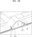
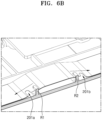
- FIGS. 5A , 5B , 6A , 6B , 7A , 7B , and 16 Details not illustrated or described in FIGS. 5A , 5B , 6A , 6B , 7A , and 7B may refer to FIGS. 1 , 2A , 2B , 3A , 3B , 4A , and 4B .
- the method of manufacturing a battery pack includes coupling the sensing board 20 to the holder H by inserting the protrusions R1 and R2 of the holder H into the holes 201a and 201b in the wavy sensing board 20, respectively (S1), maintaining a free state in which the waviness of the sensing board 20 coupled to the protrusions R1 and R2 is released to a certain extent by the tensile force of the sensing board 20 and while no external force is applied to the sensing board 20 (S2).
- the sensing terminals 30 are moved, absorbing, by the sensing board 20 coupled to the sensing terminals 30, a displacement of the sensing terminals 30 while being stretched in accordance with movements of the sensing terminals 30 (S3).
- the sensing board 20 is brought into an unstretched (i.e. maximally wavy, or a wave with maximum amplitude) state such that the center portions of the holes 201a and 201b are located at uppermost positions and, thus, the hole portions 201a and 201b are located to correspond to the protrusions R1 and R2, respectively. Then, the sensing board 20 may be coupled to the holder H by inserting the protrusion upper portions R11 and R21 into the first hole portions 201a1 and 201b1 corresponding to the protrusion upper portions R11 and R21, respectively.
- unstretched i.e. maximally wavy, or a wave with maximum amplitude
- the protrusion upper portions R11 and R21 may be caught by the second hole portions 201a2 and 201b2 such that the sensing board 20 may be caught by and coupled to the protrusions R1 and R2.
- the sensing board 20 when the sensing board 20 is coupled to the protrusions R1 and R2, the external force applied to make the sensing board 20 unstretched when coupling the sensing board 20 to the protrusions R1 and R2 is released, the waviness of the sensing board 20 is released to a certain extent (i.e. the sensing board 20 reverts to a geometry having a waviness with a magnitude greater than zero and less than the aforementioned maximum amplitude) by the tensile force of the sensing board 20 and, thus, a free state in which no external force is applied to the sensing board 20 may be maintained (S2). In this configuration, the waviness of the sensing board 20 does not become zero, and the sensing board 20 may be kept coupled to the protrusions R1 and R2 while being wavy to a certain extent.
- the sensing board 20 coupled to the sensing terminals 30 may be stretched in accordance with movements of the sensing terminals 30 and, thus, absorbs a displacement of the sensing terminals 30 (S3).
- FIG. 8 is a diagram illustrating a plurality of sensing boards arranged in a process of manufacturing sensing boards according to embodiments of the present disclosure.
- the sensing boards according to embodiments may be arranged in the manufacturing process such that edges 200n1 and 200n2 of two adjacent sensing boards 20n1 and 20n2 are parallel to each other.
- Conventional sensing boards including sensing terminals having an S-curve shape (e.g., a meandering shape) need to be manufactured with a wide interval G between the boards during the manufacturing process to avoid interference between the sensing terminals. Because the area occupied by one sensing board increases by the interval G, the productivity and efficiency may decrease.
- the sensing boards 20 are formed to have a substantially rectangular shape and adjacent edge portions are parallel to each other in the manufacturing process, the manufacture may be seamlessly performed even when the interval G between the sensing boards in the manufacturing process is narrow.
- the area occupied by the sensing boards being manufactured may be reduced, and the overall productivity and efficiency of the sensing boards may be improved with an increase in the number of manufactured sensing boards per unit area.
- the edge of the sensing board 20 is formed in a straight line shape. Thus, mold processing is simplified, and process simplification and production cost reduction may be achieved.
- FIG. 9 is a diagram illustrating a plurality of non-overlapping circuit paths inside a sensing board according to embodiments of the present disclosure.
- the sensing board 20 may have a sensing board height h. This is because, as illustrated in FIG. 8 , the interval G between sensing boards during the manufacturing process may be reduced or minimized such that the height h of each sensing board 20 may be increased or maximized. By maximizing the height h of the sensing board 20, a circuit implementation space arranged inside the sensing board 20 increases, and thus, the performance of the sensing board 20 may be improved.
- the sensing board 20 has a first area A1 forming an edge portion of the sensing board 20 and a second area A2 forming an inner edge portion of the sensing board 20, a sensing terminal connecting portion 31 formed at an end of the sensing terminal 30 and electrically connected to the sensing board 20 passes through the first area A1 to be coupled to the second area A2 of the sensing board 20, and circuit paths in the sensing board 20 include a first circuit path P1 formed in the sensing board 20 in the first direction Z1, a second circuit path P2 passing through the first area A1 of the sensing board 20 to be electrically connected to the sensing terminal 30 and another sensing terminal 30', and a third circuit path P3 electrically connected to the sensing terminal connecting portion 31 of the sensing terminal 30 in the second area A2 of the sensing board 20.
- the first, second, and third circuit paths P1, P2, and P3 do not overlap each other. That is, according to the illustrated embodiment, because the second circuit path P2 connected to the other sensing terminal 30' has a circuit path structure in which the second circuit path P2 passes through the first area A1 at where the sensing terminal 30 is arranged (e.g., other than the sensing terminal connecting portion 31 included in the second area A2 of the sensing board 20) to be connected to the other sensing terminal 30', the circuit paths P1 and P2 are respectively connected to the sensing terminals 30 and 30' without overlapping each other, and thus, the circuit performance of the sensing board 20 may be secured.
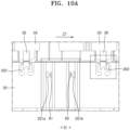
- FIG. 10A is a diagram illustrating a structure of a sensing board and sensing terminals coupled thereto according to embodiments of the present disclosure.
- FIG. 10B includes diagrams showing that when displacement of the sensing terminals shown in FIG. 10A occurs, the sensing board is stretched to absorb the displacement by up to a first displacement value D1.
- FIG. 10C is includes diagrams showing that when displacement of the sensing terminals shown in FIG. 10A occurs, sensing board connecting portions are deformed in a direction perpendicular to a connection direction between the sensing board connecting portions and the sensing terminals to absorb the displacement by up to a second displacement value D2.
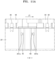
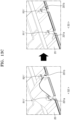
- FIG. 11A is a diagram illustrating a structure of a sensing board and sensing terminals coupled thereto according to embodiments of the present disclosure.
- FIG. 11B includes diagrams showing that when displacement of the sensing terminals shown in FIG. 11A occurs, the sensing board is stretched to absorb the displacement by up to a first displacement value D1'.
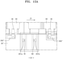
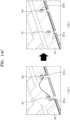
- FIG. 12A is a diagram illustrating a structure of a sensing board and sensing terminals coupled thereto according to embodiments of the present disclosure.
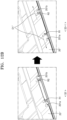
- FIG. 12B includes diagrams showing that when displacement of the sensing terminals shown in FIG. 12A occurs, the sensing board is stretched to absorb the displacement by up to a first displacement value D1".
- FIG. 12C includes diagrams showing that when a displacement of the sensing terminals shown in FIG. 12A occurs, sensing board connecting portions are deformed in a direction perpendicular to a connection direction between the sensing board connecting portions and the sensing terminals to absorb the displacement by up to a second displacement value D2".
- the sensing board 20, may further include sensing board connecting portions 202 connecting the sensing terminals 30 to the sensing board 20, and each of the sensing board connecting portions 202 may be connected to a portion of the sensing board 20 in a direction perpendicular to the first direction Z1.
- the sensing board connecting portion 202 may be arranged inside a recessed portion of the sensing board 20 and may be locally connected to only a portion of the sensing board 20 forming the recessed portion.
- the connection direction between the sensing board connecting portion 202 and the sensing board 20 may be a direction perpendicular to the first direction Z1.
- the sensing board 20 When displacement of the sensing terminals 30 in the first direction Z1 occurs, as illustrated in FIG. 10B , the sensing board 20 may be stretched in the first direction Z1 to absorb the displacement by up to the first displacement value D1.
- the sensing board connecting portions 202 may be deformed in a direction perpendicular to the connection direction (e.g., in the first direction Z1) to absorb the displacement by up to the second displacement value D2.
- the sensing board connecting portions 202 may absorb the displacement while tilting (or rotating) in the first direction Z1 with respect to the sensing board 20, and their maximum tilt angle may be the second displacement value D2.
- the absorbing, by the sensing board 20 coupled to the sensing terminals 30, of the displacement of the sensing terminals 30 while being stretched in accordance with movements of the sensing terminals 30 (S3) may include, when displacement of the sensing terminals 30 in the first direction Z1 occurs, absorbing, by the sensing board 20 being stretched in the first direction Z1, the displacement by up to the first displacement value D1 (S3-1), and absorbing, by the sensing board connecting portions 202 being deformed in a direction perpendicular to the connection direction, the displacement by up to the second displacement value D2 (S3-2).
- a sensing board 20' of a battery pack may not include the sensing board connecting portions 202.
- the sensing board 20' may be stretched in the first direction Z1 to absorb the displacement by up to the first displacement value D1'.
- a sensing board 20" of a battery pack may further include sensing board connecting portions 202" connecting the sensing terminals 30 to the sensing board 20", and each of the sensing board connecting portions 202" may be connected to a portion of the sensing board 20" in a direction perpendicular to the first direction Z1.
- the sensing board connecting portion 202" may be arranged inside a recessed portion of the sensing board 20" and may be locally connected to only a portion of the sensing board 20" forming the recessed portion.
- the connection direction between the sensing board connecting portion 202" and the sensing board 20" may be a direction parallel to the first direction Z1.
- the sensing board 20" When displacement of the sensing terminals 30 in the first direction Z1 occurs, as illustrated in FIG. 12B , the sensing board 20" may be stretched in the first direction Z1 to absorb the displacement by up to the first displacement value D1". In addition, as illustrated in FIG. 12C , the sensing board connecting portions 202" may be deformed in a direction parallel to the connection direction (e.g., in the first direction Z1) to absorb the displacement by up to the second displacement value D2".
- the absorbing, by the sensing board 20" coupled to the sensing terminals 30, of the displacement of the sensing terminals 30 while being stretched in accordance with movements of the sensing terminals 30 may include, when a displacement of the sensing terminals 30 in the first direction Z1 occurs, absorbing, by the sensing board 20", the displacement by up to the first displacement value D1 by being stretched in the first direction Z1 (S3-1), and absorbing, by the sensing board connecting portions 202" being deformed in a direction parallel to the connection direction, the displacement by up to the second displacement value D2" (S3-2).
- FIG. 13A is a diagram illustrating protrusion connecting portions of a holder inserted into holes in a sensing board, respectively, according to embodiments of the present disclosure.
- FIG. 13B is a diagram illustrating protrusion upper portions coupled to the protrusion connecting portions shown in FIG. 13A by using a heat stacking method.
- FIG. 13C includes diagrams showing the sensing board shown in FIG. 13B stretched to be flat.
- FIG. 14A is a diagram illustrating protrusion connecting portions of a holder inserted into holes in a sensing board, respectively, according to embodiments of the present disclosure.
- FIG. 14B is a diagram illustrating protrusion upper portions formed as caps fitted into the protrusion connecting portions shown in FIG. 14A , respectively.
- FIG. 14C includes diagrams showing the sensing board shown in FIG. 14B stretched to be flat.
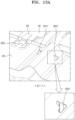
- FIG. 15A is a diagram illustrating unspread snap-fit portions of a holder inserted into holes in a sensing board, respectively, according to embodiments of the present disclosure.
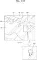
- FIG. 15B is a diagram illustrating, after insertion of the snap-fit portions into the holes in the sensing board shown in FIG. 15A , the sensing board coupled to the snap-fit portions by releasing an external force applied to the snap-fit portions such that the snap-fit portions are spread.
- FIG. 15C includes diagrams showing the sensing board shown in FIG. 15B stretched to be flat.
- protrusion upper portions R11' and R21' may be coupled to protrusion connecting portions R12' and R22' by using a heat stacking method.
- the coupling of the sensing board 20 to the holder H by inserting the protrusions of the holder into the holes in the wavy sensing board 20, respectively (S1) may include inserting the protrusion connecting portions R12' and R22' of the holder H into the holes 201a and 201b in the sensing board 20, respectively (S1-1), and coupling the protrusion connecting portions R12' and R22' to the protrusion upper portions R11' and R21' extending through the holes 201a and 201b, respectively (S1-2).
- the sensing board 20 may be more easily coupled to the protrusion connecting portions R12' and R22' without the protrusion upper portion being present during the insertion.
- the sensing board 20 may be completely coupled to the protrusions by coupling the protrusion upper portions R11' and R21' to the protrusion connecting portions R12' and R22' protruding from the sensing board 20.
- the protrusion upper portions R11' and R21' may have a wider width than the protrusion connecting portions R12' and R22' and the hole portions 201a and 201b.
- the sensing board 20 cannot escape from (e.g., cannot become detached from) due to the protrusions R1' and R2'.
- the protrusion upper portions R11' and R21' may be integrally formed by thermal compression.
- Such a coupling structure and method may be sufficiently implemented in an automated manufacturing process.
- protrusion upper portions R11" and R21" may be formed as caps and may be fitted onto protrusion connecting portions R12" and R22".
- the coupling of the sensing board 20 to the holder H by inserting the protrusions of the holder H into the holes in the wavy sensing board 20, respectively (S1) may include inserting the protrusion connecting portions R12" and R22" of the holder H into the holes 201a and 201b in the sensing board 20, respectively (S1-1), and coupling the protrusion connecting portions R12” and R22” to the protrusion upper portions R11" and R21" extending through the holes 201a and 201b, respectively (S1-2).
- the sensing board 20 may be more easily coupled to the protrusion connecting portions R12" and R22" without the protrusion upper portion being present during the insertion.
- the sensing board 20 may be completely coupled to the protrusions by fitting the protrusion upper portions R1 1' and R21' onto the protrusion connecting portions R12" and R22" protruding from the sensing board 20.
- the protrusion upper portions R11" and R21" may have a wider width than the protrusion connecting portions R12" and R22” and the hole portions 201a and 201b.
- the sensing board 20 cannot escape from (e.g., cannot become detached) from protrusions R1" and R2".
- the protrusion upper portions R11" and R21" may be fixed together.
- Such a coupling structure and method may be sufficiently implemented in an automated manufacturing process.
- the protrusion upper portions R11′′′ and R21′′′ may include snap-fit portions R1′′′ and R2′′′, and the snap-fit portions R1′′′ and R2′′′ may be snap-fit to the sensing board 20.
- the coupling of the sensing board 20 to the holder H by inserting the protrusions of the holder H into the holes in the wavy sensing board 20, respectively (S1) may include inserting protrusion connecting portions R12′′′ and R22′′′ of the holder into the holes 201a and 201b in the sensing board 20, respectively (S1-1), and coupling the protrusion connecting portions R12′′′ and R22′′′ to the protrusion upper portions R11′′′ and R21′′′ coupled to the holes 201a and 201b, respectively (S1-2).
- the sensing board 20 may be coupled to the inside of (e.g., may be coupled under) the snap-fit portions R1′′′ and R2'".
- Such a coupling structure and method may be sufficiently implemented in an automated manufacturing process.
- a wavy sensing board may absorb the corresponding displacement of the battery cell and sensing terminals connected to the battery cell.
Landscapes
- Chemical & Material Sciences (AREA)
- Chemical Kinetics & Catalysis (AREA)
- Electrochemistry (AREA)
- General Chemical & Material Sciences (AREA)
- Engineering & Computer Science (AREA)
- Manufacturing & Machinery (AREA)
- Physics & Mathematics (AREA)
- General Physics & Mathematics (AREA)
- Battery Mounting, Suspending (AREA)
- Connection Of Batteries Or Terminals (AREA)
Applications Claiming Priority (2)
| Application Number | Priority Date | Filing Date | Title |
|---|---|---|---|
| KR20230039784 | 2023-03-27 | ||
| KR1020230083599A KR20240145350A (ko) | 2023-03-27 | 2023-06-28 | 배터리 팩 및 배터리 팩 제조 방법 |
Publications (2)
| Publication Number | Publication Date |
|---|---|
| EP4439786A2 true EP4439786A2 (de) | 2024-10-02 |
| EP4439786A3 EP4439786A3 (de) | 2025-01-29 |
Family
ID=90417478
Family Applications (1)
| Application Number | Title | Priority Date | Filing Date |
|---|---|---|---|
| EP24165231.2A Pending EP4439786A3 (de) | 2023-03-27 | 2024-03-21 | Batteriepack und verfahren zur herstellung des batteriepacks |
Country Status (3)
| Country | Link |
|---|---|
| US (1) | US20240332758A1 (de) |
| EP (1) | EP4439786A3 (de) |
| JP (1) | JP2024139764A (de) |
Family Cites Families (7)
| Publication number | Priority date | Publication date | Assignee | Title |
|---|---|---|---|---|
| JP5702947B2 (ja) * | 2010-04-22 | 2015-04-15 | 矢崎総業株式会社 | 配線材 |
| CN107732607B (zh) * | 2016-08-12 | 2024-04-09 | 泰科电子(上海)有限公司 | 引线框架、连接组件、信号采样装置及电池包 |
| JP6986504B2 (ja) * | 2018-11-22 | 2021-12-22 | 株式会社オートネットワーク技術研究所 | 接続モジュール |
| JP7212504B2 (ja) * | 2018-11-22 | 2023-01-25 | 株式会社オートネットワーク技術研究所 | 接続モジュール |
| JP7403240B2 (ja) * | 2019-06-07 | 2023-12-22 | 日本メクトロン株式会社 | 配線材及びバッテリモジュール |
| WO2021199534A1 (ja) * | 2020-03-31 | 2021-10-07 | 三洋電機株式会社 | 電源装置及びこれを備える車両並びに蓄電装置 |
| CN114122627B (zh) * | 2020-08-27 | 2024-08-09 | 莫仕连接器(成都)有限公司 | 电池连接模块 |
-
2023
- 2023-10-27 US US18/496,486 patent/US20240332758A1/en active Pending
-
2024
- 2024-03-21 EP EP24165231.2A patent/EP4439786A3/de active Pending
- 2024-03-26 JP JP2024049761A patent/JP2024139764A/ja active Pending
Also Published As
| Publication number | Publication date |
|---|---|
| JP2024139764A (ja) | 2024-10-09 |
| EP4439786A3 (de) | 2025-01-29 |
| US20240332758A1 (en) | 2024-10-03 |
Similar Documents
| Publication | Publication Date | Title |
|---|---|---|
| KR102303827B1 (ko) | 다수의 전극조립체를 구비하는 복합전극조립체 및 이를 포함하는 전기화학소자 | |
| TWI869543B (zh) | 具有匯流排的電池模組、電池組以及運輸工具 | |
| US10270138B2 (en) | Battery module with a fixture for a temperature sensitive element | |
| US11742547B2 (en) | Battery module and battery pack having the same | |
| US9240618B2 (en) | Rechargeable battery and battery module | |
| US11424514B2 (en) | Battery module having electrode tab with protrusion | |
| KR102942276B1 (ko) | 전지 모듈 | |
| EP4439786A2 (de) | Batteriepack und verfahren zur herstellung des batteriepacks | |
| EP4095990A1 (de) | Batteriezelle, batteriepack und elektronische vorrichtung | |
| EP3358649B1 (de) | Stromableitersystem eines batteriemoduls | |
| EP4524530A1 (de) | Batteriemodul | |
| CN110544759B (zh) | 电池单池和电池模块 | |
| CN119725663A (zh) | 可再充电电池 | |
| EP4258425B1 (de) | Batteriemodul sowie batteriepack und fahrzeug damit | |
| KR101174964B1 (ko) | 이차 전지 및 그의 전극 조립체 제조 방법 | |
| KR102930968B1 (ko) | 이차 전지 및 전지 모듈 | |
| CN118712675A (zh) | 电池组和制造该电池组的方法 | |
| KR20240145350A (ko) | 배터리 팩 및 배터리 팩 제조 방법 | |
| US20250233282A1 (en) | Busbar assembly and battery module including the same | |
| US20250158195A1 (en) | Secondary battery module | |
| EP4568006A1 (de) | Batteriemodul | |
| US20250132435A1 (en) | Case, battery module comprising case, and manufacturing method of case | |
| US20260088334A1 (en) | Secondary battery module | |
| KR20250119023A (ko) | 버스바 조립체 및 센서 조립체를 포함하는 배터리 모듈 및 이를 포함하는 배터리 팩 | |
| KR20250144567A (ko) | 터미널 버스바가 구비된 버스바 어셈블리 및 이를 포함하는 배터리 모듈 |
Legal Events
| Date | Code | Title | Description |
|---|---|---|---|
| PUAI | Public reference made under article 153(3) epc to a published international application that has entered the european phase |
Free format text: ORIGINAL CODE: 0009012 |
|
| STAA | Information on the status of an ep patent application or granted ep patent |
Free format text: STATUS: REQUEST FOR EXAMINATION WAS MADE |
|
| 17P | Request for examination filed |
Effective date: 20240321 |
|
| AK | Designated contracting states |
Kind code of ref document: A2 Designated state(s): AL AT BE BG CH CY CZ DE DK EE ES FI FR GB GR HR HU IE IS IT LI LT LU LV MC ME MK MT NL NO PL PT RO RS SE SI SK SM TR |
|
| PUAL | Search report despatched |
Free format text: ORIGINAL CODE: 0009013 |
|
| AK | Designated contracting states |
Kind code of ref document: A3 Designated state(s): AL AT BE BG CH CY CZ DE DK EE ES FI FR GB GR HR HU IE IS IT LI LT LU LV MC ME MK MT NL NO PL PT RO RS SE SI SK SM TR |
|
| RIC1 | Information provided on ipc code assigned before grant |
Ipc: H01M 50/211 20210101ALN20241220BHEP Ipc: G01R 31/364 20190101ALI20241220BHEP Ipc: H01M 50/569 20210101ALI20241220BHEP Ipc: H01M 50/507 20210101ALI20241220BHEP Ipc: H01M 50/503 20210101ALI20241220BHEP Ipc: H01M 10/48 20060101AFI20241220BHEP |