EP4439774A1 - Ccs assembly, battery module and battery pack - Google Patents
Ccs assembly, battery module and battery pack Download PDFInfo
- Publication number
- EP4439774A1 EP4439774A1 EP23213167.2A EP23213167A EP4439774A1 EP 4439774 A1 EP4439774 A1 EP 4439774A1 EP 23213167 A EP23213167 A EP 23213167A EP 4439774 A1 EP4439774 A1 EP 4439774A1
- Authority
- EP
- European Patent Office
- Prior art keywords
- collecting
- collecting terminal
- temperature
- blocking part
- adhesive
- Prior art date
- Legal status (The legal status is an assumption and is not a legal conclusion. Google has not performed a legal analysis and makes no representation as to the accuracy of the status listed.)
- Pending
Links
- 230000001070 adhesive effect Effects 0.000 claims abstract description 126
- 239000000853 adhesive Substances 0.000 claims abstract description 125
- 230000000903 blocking effect Effects 0.000 claims abstract description 71
- 239000004033 plastic Substances 0.000 claims abstract description 39
- 238000000926 separation method Methods 0.000 claims abstract description 28
- 102100021283 1-aminocyclopropane-1-carboxylate synthase-like protein 1 Human genes 0.000 claims 1
- 101000675558 Homo sapiens 1-aminocyclopropane-1-carboxylate synthase-like protein 1 Proteins 0.000 claims 1
- 210000004027 cell Anatomy 0.000 description 34
- 238000004519 manufacturing process Methods 0.000 description 7
- 238000000034 method Methods 0.000 description 6
- 238000012546 transfer Methods 0.000 description 5
- 238000000576 coating method Methods 0.000 description 4
- 238000012545 processing Methods 0.000 description 4
- 238000001514 detection method Methods 0.000 description 3
- 238000010586 diagram Methods 0.000 description 3
- 239000011248 coating agent Substances 0.000 description 2
- 230000000694 effects Effects 0.000 description 2
- RYGMFSIKBFXOCR-UHFFFAOYSA-N Copper Chemical compound [Cu] RYGMFSIKBFXOCR-UHFFFAOYSA-N 0.000 description 1
- 239000004642 Polyimide Substances 0.000 description 1
- 230000002159 abnormal effect Effects 0.000 description 1
- 230000004931 aggregating effect Effects 0.000 description 1
- 229910052782 aluminium Inorganic materials 0.000 description 1
- XAGFODPZIPBFFR-UHFFFAOYSA-N aluminium Chemical compound [Al] XAGFODPZIPBFFR-UHFFFAOYSA-N 0.000 description 1
- 229910052802 copper Inorganic materials 0.000 description 1
- 239000010949 copper Substances 0.000 description 1
- 230000007547 defect Effects 0.000 description 1
- 238000013461 design Methods 0.000 description 1
- 239000006260 foam Substances 0.000 description 1
- 230000017525 heat dissipation Effects 0.000 description 1
- 230000002452 interceptive effect Effects 0.000 description 1
- 239000000463 material Substances 0.000 description 1
- 239000007769 metal material Substances 0.000 description 1
- 239000000203 mixture Substances 0.000 description 1
- 239000002985 plastic film Substances 0.000 description 1
- 229920006267 polyester film Polymers 0.000 description 1
- 229920001721 polyimide Polymers 0.000 description 1
- 238000003825 pressing Methods 0.000 description 1
- 238000009877 rendering Methods 0.000 description 1
- 230000035939 shock Effects 0.000 description 1
- 238000012360 testing method Methods 0.000 description 1
Images


Classifications
-
- H—ELECTRICITY
- H01—ELECTRIC ELEMENTS
- H01M—PROCESSES OR MEANS, e.g. BATTERIES, FOR THE DIRECT CONVERSION OF CHEMICAL ENERGY INTO ELECTRICAL ENERGY
- H01M50/00—Constructional details or processes of manufacture of the non-active parts of electrochemical cells other than fuel cells, e.g. hybrid cells
- H01M50/20—Mountings; Secondary casings or frames; Racks, modules or packs; Suspension devices; Shock absorbers; Transport or carrying devices; Holders
- H01M50/204—Racks, modules or packs for multiple batteries or multiple cells
-
- H—ELECTRICITY
- H01—ELECTRIC ELEMENTS
- H01M—PROCESSES OR MEANS, e.g. BATTERIES, FOR THE DIRECT CONVERSION OF CHEMICAL ENERGY INTO ELECTRICAL ENERGY
- H01M10/00—Secondary cells; Manufacture thereof
- H01M10/42—Methods or arrangements for servicing or maintenance of secondary cells or secondary half-cells
- H01M10/425—Structural combination with electronic components, e.g. electronic circuits integrated to the outside of the casing
-
- H—ELECTRICITY
- H01—ELECTRIC ELEMENTS
- H01M—PROCESSES OR MEANS, e.g. BATTERIES, FOR THE DIRECT CONVERSION OF CHEMICAL ENERGY INTO ELECTRICAL ENERGY
- H01M10/00—Secondary cells; Manufacture thereof
- H01M10/42—Methods or arrangements for servicing or maintenance of secondary cells or secondary half-cells
- H01M10/48—Accumulators combined with arrangements for measuring, testing or indicating the condition of cells, e.g. the level or density of the electrolyte
- H01M10/482—Accumulators combined with arrangements for measuring, testing or indicating the condition of cells, e.g. the level or density of the electrolyte for several batteries or cells simultaneously or sequentially
-
- H—ELECTRICITY
- H01—ELECTRIC ELEMENTS
- H01M—PROCESSES OR MEANS, e.g. BATTERIES, FOR THE DIRECT CONVERSION OF CHEMICAL ENERGY INTO ELECTRICAL ENERGY
- H01M10/00—Secondary cells; Manufacture thereof
- H01M10/42—Methods or arrangements for servicing or maintenance of secondary cells or secondary half-cells
- H01M10/48—Accumulators combined with arrangements for measuring, testing or indicating the condition of cells, e.g. the level or density of the electrolyte
- H01M10/486—Accumulators combined with arrangements for measuring, testing or indicating the condition of cells, e.g. the level or density of the electrolyte for measuring temperature
-
- H—ELECTRICITY
- H01—ELECTRIC ELEMENTS
- H01M—PROCESSES OR MEANS, e.g. BATTERIES, FOR THE DIRECT CONVERSION OF CHEMICAL ENERGY INTO ELECTRICAL ENERGY
- H01M50/00—Constructional details or processes of manufacture of the non-active parts of electrochemical cells other than fuel cells, e.g. hybrid cells
- H01M50/50—Current conducting connections for cells or batteries
- H01M50/502—Interconnectors for connecting terminals of adjacent batteries; Interconnectors for connecting cells outside a battery casing
- H01M50/507—Interconnectors for connecting terminals of adjacent batteries; Interconnectors for connecting cells outside a battery casing comprising an arrangement of two or more busbars within a container structure, e.g. busbar modules
-
- H—ELECTRICITY
- H01—ELECTRIC ELEMENTS
- H01M—PROCESSES OR MEANS, e.g. BATTERIES, FOR THE DIRECT CONVERSION OF CHEMICAL ENERGY INTO ELECTRICAL ENERGY
- H01M50/00—Constructional details or processes of manufacture of the non-active parts of electrochemical cells other than fuel cells, e.g. hybrid cells
- H01M50/50—Current conducting connections for cells or batteries
- H01M50/502—Interconnectors for connecting terminals of adjacent batteries; Interconnectors for connecting cells outside a battery casing
- H01M50/519—Interconnectors for connecting terminals of adjacent batteries; Interconnectors for connecting cells outside a battery casing comprising printed circuit boards [PCB]
-
- H—ELECTRICITY
- H01—ELECTRIC ELEMENTS
- H01M—PROCESSES OR MEANS, e.g. BATTERIES, FOR THE DIRECT CONVERSION OF CHEMICAL ENERGY INTO ELECTRICAL ENERGY
- H01M50/00—Constructional details or processes of manufacture of the non-active parts of electrochemical cells other than fuel cells, e.g. hybrid cells
- H01M50/50—Current conducting connections for cells or batteries
- H01M50/569—Constructional details of current conducting connections for detecting conditions inside cells or batteries, e.g. details of voltage sensing terminals
-
- H—ELECTRICITY
- H01—ELECTRIC ELEMENTS
- H01M—PROCESSES OR MEANS, e.g. BATTERIES, FOR THE DIRECT CONVERSION OF CHEMICAL ENERGY INTO ELECTRICAL ENERGY
- H01M10/00—Secondary cells; Manufacture thereof
- H01M10/42—Methods or arrangements for servicing or maintenance of secondary cells or secondary half-cells
- H01M10/425—Structural combination with electronic components, e.g. electronic circuits integrated to the outside of the casing
- H01M2010/4271—Battery management systems including electronic circuits, e.g. control of current or voltage to keep battery in healthy state, cell balancing
-
- H—ELECTRICITY
- H01—ELECTRIC ELEMENTS
- H01M—PROCESSES OR MEANS, e.g. BATTERIES, FOR THE DIRECT CONVERSION OF CHEMICAL ENERGY INTO ELECTRICAL ENERGY
- H01M50/00—Constructional details or processes of manufacture of the non-active parts of electrochemical cells other than fuel cells, e.g. hybrid cells
- H01M50/20—Mountings; Secondary casings or frames; Racks, modules or packs; Suspension devices; Shock absorbers; Transport or carrying devices; Holders
- H01M50/204—Racks, modules or packs for multiple batteries or multiple cells
- H01M50/207—Racks, modules or packs for multiple batteries or multiple cells characterised by their shape
- H01M50/209—Racks, modules or packs for multiple batteries or multiple cells characterised by their shape adapted for prismatic or rectangular cells
-
- Y—GENERAL TAGGING OF NEW TECHNOLOGICAL DEVELOPMENTS; GENERAL TAGGING OF CROSS-SECTIONAL TECHNOLOGIES SPANNING OVER SEVERAL SECTIONS OF THE IPC; TECHNICAL SUBJECTS COVERED BY FORMER USPC CROSS-REFERENCE ART COLLECTIONS [XRACs] AND DIGESTS
- Y02—TECHNOLOGIES OR APPLICATIONS FOR MITIGATION OR ADAPTATION AGAINST CLIMATE CHANGE
- Y02E—REDUCTION OF GREENHOUSE GAS [GHG] EMISSIONS, RELATED TO ENERGY GENERATION, TRANSMISSION OR DISTRIBUTION
- Y02E60/00—Enabling technologies; Technologies with a potential or indirect contribution to GHG emissions mitigation
- Y02E60/10—Energy storage using batteries
Definitions
- the present application relates to the field of batteries, in particular to a CCS assembly, a battery module and a battery pack.
- Flexible circuit board is a printed circuit based on polyester film or polyimide with high reliability and excellent flexibility. By embedding the designed circuits on a thin, lightweight plastic sheet that is bendable, a large amount of precision elements is stacked in a narrow and limited space, forming a bendable and flexible circuit. Flexible circuit boards may be freely bent and folded, light weight, small size, good heat dissipation, and easy to install, breaking through the traditional interconnection technology, and are widely used in the CCS assembly of battery packs.
- a heat-conductive adhesive is used to reinforce and conduct heat between the collecting terminals of the flexible circuit board and the cell.
- a heat-conductive adhesive is used to reinforce and conduct heat between the collecting terminals of the flexible circuit board and the cell.
- a CCS assembly In order to overcome at least one of the defects of the prior art mentioned above, provided in the present application is a CCS assembly, a battery module and a battery pack, solving the problem that the heat-conductive adhesive between the collecting terminal of the existing flexible circuit board and the cell is prone to overflow during the coating process.
- a CCS assembly including:
- the adhesive blocking part includes a first lateral frame and a second lateral frame; the first lateral frame and the second lateral frame are vertically distributed in an L shape; and the first lateral frame and the second lateral frame are both fixedly connected to the plastic supporting frame.
- the adhesive blocking part includes two first lateral frames and two second lateral frames; two first lateral frames are provided oppositely and two second lateral frames are provided oppositely; and two first lateral frames and two second lateral frames are enclosed in a square structure.
- an interior of the temperature-sensing collecting zone is also provided with a first positioning line; the first positioning line is extended in a length direction of the flexible circuit board; and the collecting terminal is assembled in the interior of the temperature-sensing collecting zone and is aligned with the first positioning line, so that the separation distance is formed between the collecting terminal and the adhesive blocking part.
- the interior of the temperature-sensing collecting zone is also provided with a second positioning line; the second positioning line is perpendicular to the first positioning line; and the collecting terminal is assembled in the interior of the temperature-sensing collecting zone and is aligned with the second positioning line, so that the separation distance is formed between the collecting terminal and the adhesive blocking part.
- a plurality of the temperature-sensing collecting zones are provided on the plastic supporting frame in a length direction of the flexible circuit board; an edge of each temperature-sensing collecting zone is provided with the adhesive blocking part; a plurality of the collecting terminals are provided on the flexible circuit board; each collecting terminal is provided corresponding to each adhesive blocking part; and each collecting terminal is provided in an interior of each adhesive blocking part.
- the collecting terminal includes a temperature sensing member and a collection supporting part, the temperature sensing member being fixedly connected to the collection supporting part, the collection supporting part being fixedly connected to the flexible circuit board.
- thermally conductive adhesive is poured on the collecting terminal, used for thermally conductively connecting the collecting terminal to the cell.
- a battery module including
- a plurality of the collecting terminals are provided on the flexible circuit board, and a plurality of the collecting terminals are thermally conductively connected to a plurality of cells of the battery pack.
- a height of the collecting terminal is greater than that of the adhesive blocking part, so that the collecting terminal abuts the cell of the battery pack.
- a battery pack including the battery module mentioned above.
- a CCS assembly, a battery module and a battery pack provided in the present application provide technical effects as follows:
- the structure of the adhesive blocking part is used to allow the excess adhesive (i.e., heat-conductive adhesive of the prior art) to be restrained and stored in an interior of the adhesive blocking part when an excessive amount of adhesive is injected into the collecting terminal provided within the temperature-sensing collecting zone. More ingeniously, a separation distance between the adhesive blocking part and the collecting terminal is provided so that excess adhesive is diffused to be accommodated within the range of the separation distance, thereby ensuring that no or only a small amount of adhesive is in contact with the adhesive blocking part.
- excess adhesive i.e., heat-conductive adhesive of the prior art
- Labels 11 flexible circuit board; 12 collecting terminal; 121 temperature sensing member; 122 collection supporting part; 21 plastic supporting frame; 22 adhesive blocking part; 221 first lateral frame; 222 second lateral frame; 3 separation distance; 41 first positioning line; 42 second positioning line.
- Flexible circuit board 11 also known as FPC, which provides good properties such as light weight, thin thickness, and good bendability, has been widely used in battery packs and battery products, enabling battery packs and battery products to provide more prominent advantages in terms of such as safety, light weight, and layout regularity.
- the flexible circuit board 11 is used in battery packs and battery products as a collecting harness for testing, collecting voltage and detecting temperature.
- a CCS assembly including:
- a plastic supporting frame 21 cooperating with the flexible circuit board 11 may better ensure the lightweight of the CCS assembly, and also enable the structure of the CCS assembly to be lighter, more cost-saving, and also improve the processing efficiency.
- the temperature-sensing collecting zone is projected onto a surface of the corresponding cell to form temperature-sensing collecting points on the cell.
- Thermally conductive adhesive is poured on the collecting terminal 12 to achieve the objective of thermal conductive connection between the collecting terminal 12 and the cell.
- the collecting terminal 12 is stably fixed on the corresponding cell, so as to avoid the risk of loosening between the flexible circuit board 11 and the cell.
- the temperature of the cell may be steadily transferred to the collecting terminal 12 through the heat-conductive adhesive, thereby enabling the collecting terminal 12 to continuously collect the temperature signal of the cell.
- the adhesive is not limited to the heat-conductive adhesive mentioned above.
- Other adhesives that may achieve the thermal conductive connection between the collecting terminal 12 and the cell are all may be used as adhesive for replacing the heat-conductive adhesive in the present embodiment.
- the adhesive is rendered not to diffuse and flow over a large area towards a periphery of the collecting terminal 12.
- the excess adhesive may be constrained in the interior of the adhesive blocking part 22, which solves the risk that the collecting terminal 12 of the flexible circuit board 11 is prone to overflow of adhesive during the process of applying adhesive.
- a separation distance 3 is provided between the collecting terminal 12 and a side wall of the adhesive blocking part 22, in which the separation distance 3 is used to accommodate the excess adhesive, which reduces heat transfer from the plastic supporting frame 21 directly or indirectly to the collecting terminal 12 through the adhesive.
- part of the heat of the cell is transferred to the plastic supporting frame 21, and then the plastic supporting frame 21 also possesses a certain amount of heat.
- the amount of adhesive is excessive, the excess adhesive diffuses to the separation distance 3 so that a small amount of adhesive is in contact with the adhesive blocking part 22 or even no adhesive in contact with the adhesive blocking part 22, which avoids the problem of heat on the plastic supporting frame 21 aggregating to the collecting terminal 12 through the adhesive, thereby leading to interference with the accurate collection of the temperature of the cell by the collecting terminal 12.
- the problem of overflow of adhesive in the processing of the flexible circuit board 11 is solved, and the collecting accuracy of the collecting terminal 12 for the temperature of the cell is also effectively improved.
- the adhesive and the adhesive blocking part 22 are also capable of blocking the transfer of heat from the adhesive blocking part 22 to the collecting terminal 12 under the action of the separation distance 3. Therefore, in conjunction with the method of managing the amount of adhesive, it may highly effectively ensure that the collecting terminal 12 detects and collects the temperature of the cell with high accuracy.
- the adhesive blocking part 22 includes two first lateral frame 221 and two second lateral frame 222; two first lateral frame 221 are provided oppositely and two second lateral frame 222 are provided oppositely; and two first lateral frame 221 and two second lateral frame 222 are enclosed in a square structure.
- each first lateral frame 221 is connected to the adjacent second lateral frame 222, which may not only ensure that the adhesive may not infiltrate out from the adhesive blocking part 22 but may also effectively ensure an overall structural strength of the adhesive blocking part 22. Admittedly, each lateral edge of the first lateral frame 221 may also be in contact with a lateral edge of the second lateral frame 222. Alternatively, a gap exists between the first lateral frame 221 and the second lateral frame 222.
- the separation distance 3 may be suitably increased in order to achieve that, in the case of an excessive amount of adhesive, the excess adhesive is not in contact with the first lateral frame 221 or with the second lateral frame 222, in which the size of the separation distance 3 is determined and adjusted according to the structural design of the plastic supporting frame 21 and the assembly requirements of the battery, and the size of the separation distance 3 is not limited hereby.
- the adhesive blocking part 22 includes a first lateral frame 221 and a second lateral frame 22, in which the first lateral frame 221 and the second lateral frame 222 are vertically distributed in an L shape, and the first lateral frame 221 and the second lateral frame 222 are both fixedly connected to the plastic supporting frame 21.
- the first lateral frame 221 is preferably connected to the second lateral frame 222, which ensures that the adhesive may not infiltrate from the adhesive blocking part 22, and also ensures an overall structural strength of the adhesive blocking part 22. Admittedly, a lateral edge of the first lateral frame 221 may also be in contact with a lateral edge of the second lateral frame 222. Alternatively, a gap exists between the first lateral frame 221 and the second lateral frame 222.
- flexible circuit boards 11 provide a certain degree of flexibility. Assembly errors may occur when the flexible circuit board 11 and the plastic supporting frame 21 are assembled with each other.
- the collecting terminal 12 is prone to misalignment during assembly to the interior of the adhesive blocking part 22, so that the separation distance 3 is not achieved between the collecting terminal 12 and the adhesive blocking part 22, thereby causing the risk of overflow of adhesive due to inaccurate alignment of the collecting terminal 12.
- an interior of the temperature sensing collecting-zone is also provided with a first positioning line 41; the first positioning line 41 is extended in a length direction of the flexible circuit board 11; the first positioning line 41 is used as a first reference standard for assembling the collecting terminal 12 to the temperature-sensing collecting zone; and the collecting terminal 12 is assembled in the interior of the temperature sensing collecting-zone and is aligned with the first positioning line 41, so that the separation distance 3 is formed between the collecting terminal 12 and the adhesive blocking part 22.
- the first lateral frame 221 of the adhesive blocking part 22 is defined to extend in a length direction of the flexible circuit board 11, so the extension direction of the second lateral frame 222 is perpendicular to a length direction of the flexible circuit board 11. Then, the first positioning line 41 mentioned above is parallel to the first lateral frame 221, and a relative distance between the first positioning line 41 and the first lateral frame 221 is equal to the separation distance 3.
- the first positioning line 41 is used as a first reference standard.
- a lateral edge of the collecting terminal 12 is aligned with the first positioning line 41 in a direction perpendicular to the temperature-sensing collecting zone, and a relative distance between the collecting terminal 12 and the first lateral frame 221 is equal to the separation distance 3.
- the assembly accuracy of the collecting terminal 12 is improved, and the problem of inaccurate positioning of the collecting terminal 12 in the assembly process is eliminated, so as to avoid the problem of overflow of adhesive in the manufacturing process. Additionally, it also avoids the problem that the relative distance between the collecting terminal 12 and the first lateral frame 221 is reduced due to the offset and misalignment of the collecting terminal 12 resulting in the heat transfer from the adhesive blocking part 22 to the collecting terminal 12, and effectively ensures the accuracy of the detection and collection of the collecting terminal 12.
- the first positioning line 41 may be provided on the temperature-sensing collecting zone by applying, or may be provided on the temperature-sensing collecting zone by engraving, or may be a protruding structure in the form of a long strip and integrally molded with the plastic supporting frame 21.
- the interior of the temperature sensing collecting-zone is also provided with a second positioning line 42; the second positioning line 42 is perpendicular to the first positioning line 41; the second positioning line 42 is used as a second reference standard for assembling the collecting terminal 12 to the temperature-sensing collecting zone; and the collecting terminal 12 is assembled in the interior of the temperature sensing collecting-zone and is aligned with the second positioning line 42, so that the separation distance 3 is formed between the collecting terminal 12 and the adhesive blocking part 22.
- the second positioning line 42 is parallel to the second lateral frame 222, and a relative distance between the second positioning line 42 and the second lateral frame 222 is equal to the separation distance 3.
- the second positioning line 42 is used as a second reference standard. A lateral edge of the collecting terminal 12 is aligned with the second positioning line 42 in a direction perpendicular to the temperature-sensing collecting zone, and a relative distance between the collecting terminal 12 and the second lateral frame 222 is equal to the separation distance 3.
- the assembly accuracy of the collecting terminal 12 is improved, and the problem of inaccurate positioning of the collecting terminal 12 in the assembly process is eliminated, so as to avoid the problem of overflow of adhesive in the manufacturing process.
- the collecting terminal 12 may be precisely positioned in both the direction along the length of the flexible circuit board 11 and the direction perpendicular to the length of the flexible circuit board 11, so as to effectively ensure the assembly accuracy between the adhesive blocking part 22 and the collecting terminal 12, thereby effectively ensuring that the collecting terminal 12 carries out a stable and accurate collection.
- the second positioning line 42 may be provided on the temperature-sensing collecting zone by applying, or may be provided on the temperature-sensing collecting zone by engraving, or may be a protruding structure in the form of a long strip and integrally molded with the plastic supporting frame 21.
- the temperature-sensing collecting zone may be provided with only the first positioning line 41 when the collecting terminal 12 is not provided with a second lateral frame 222 in the direction of offsetting along the length of the flexible circuit board 11 of the plastic supporting frame 21.
- the collecting terminal 12 includes a temperature sensing member 121 and a collection supporting part 122, the temperature sensing member 121 being fixedly connected to the collection supporting part 122, the collection supporting part 122 being fixedly connected to the flexible circuit board 11.
- the temperature sensing member 121 is preferably thermistor, admittedly, or may be other elements for detecting temperature, such as a temperature sensor.
- the collection supporting part 122 is made of a metal material with good thermal conductivity, such as aluminum and copper. The temperature sensing member 121 abuts the cell, so that the temperature sensing member 121 may directly detect and collect the temperature of the cell, thereby achieving the objective that the collecting terminal 12 collects the temperature signal of the cell accurately and efficiently.
- a plurality of the temperature sensing collecting-zones are provided on the plastic supporting frame 3 in a length direction of the flexible circuit board 11; an edge of each temperature sensing collecting-zone is provided with the adhesive blocking part 22; a plurality of the collecting terminals are provided on the flexible circuit board 11; each collecting terminal 12 is provided corresponding to each adhesive blocking part 22; and each collecting terminal 12 is provided in an interior of each adhesive blocking part 22.
- a plurality of temperature-sensing collecting zones are evenly provided in a length direction of the flexible circuit board 11.
- a plurality of temperature-sensing collecting zones are unevenly provided in a length direction of the flexible circuit board 11.
- the adhesive blocking parts 22 may all be in an L-shaped structure, or may all be in a square-shaped structure. Admittedly, as shown in Fig. 1 and Fig. 3 , the adhesive blocking part 22 may be a mix of L-shaped and square-shaped structures.
- square-shaped adhesive blocking part 22 is provided on two ends of the flexible circuit board 11 in the length direction, and square-shaped adhesive blocking part 22 is provided on the middle part of the flexible circuit board 11.
- the battery module includes:
- the collecting terminal 12 of the flexible circuit board 11 abuts the corresponding cell of the battery pack, and is fixed and heat-conducted by adhesive, in which the adhesive is preferably a heat-conductive adhesive.
- the collecting terminal 12 may collect the temperature of the cell effectively and directly, under the combined function of the separation distance 3 and the adhesive blocking part 22, which effectively ensures the collection accuracy of the collecting terminal 12 on the temperature of the cell.
- a height of the collecting terminal 12 is greater than that of the adhesive blocking part 22. That is, the relative distance between the collecting terminal 12 for contacting and detecting the side of the cell and the temperature-sensing collecting zone is greater than a total height of the adhesive blocking part 22, so that the collecting terminal 12 may abut the cell of the battery pack. Additionally, the temperature sensing member 122 of the collecting terminal 12 is fixed to the plastic supporting frame 21 by foam adhesive.
- a plurality of collecting terminals 12 are provided on the flexible circuit board 11, and a plurality of collecting terminals 12 are thermally conductive connected to a plurality of cells of the battery pack, so that a plurality of collecting points are provided on different positions on the battery pack to acquire temperature signals of different cells, which further improves the temperature collecting accuracy of the battery pack.
- a battery pack including the battery module mentioned above.
- the temperature signal acquired form the flexible circuit board 11 of the battery module is transferred to the battery management system (BMS) of the battery pack.
- BMS battery management system
- the battery management system may stably and accurately acquire the cell temperature of the battery pack so as to accurately monitor the operating condition of the cell, which ensures the operating stability and an optimal operating performance of the battery pack and a battery production adopted the battery pack.
Landscapes
- Chemical & Material Sciences (AREA)
- Chemical Kinetics & Catalysis (AREA)
- Electrochemistry (AREA)
- General Chemical & Material Sciences (AREA)
- Engineering & Computer Science (AREA)
- Manufacturing & Machinery (AREA)
- Microelectronics & Electronic Packaging (AREA)
- Battery Mounting, Suspending (AREA)
- Secondary Cells (AREA)
Abstract
Disclosed in the present application is a CCS assembly, including a flexible circuit board, the flexible circuit board being provided with a collecting terminal, the collecting terminal being used for collecting a temperature signal of a cell; and a plastic supporting frame, the plastic supporting frame being provided with a temperature-sensing collecting zone, an edge of the temperature-sensing collecting zone being provided with an adhesive blocking part, in which the flexible circuit board is mounted and fixed on the plastic supporting frame, and the collecting terminal is provided in an interior of the adhesive blocking part, a separation distance being formed between the collecting terminal and a side wall of the adhesive blocking part.
Description
- The present application claims priority of
Chinese Patent Application No.202320704342.6 filed on March 31, 2023 - The present application relates to the field of batteries, in particular to a CCS assembly, a battery module and a battery pack.
- Flexible circuit board (FPC) is a printed circuit based on polyester film or polyimide with high reliability and excellent flexibility. By embedding the designed circuits on a thin, lightweight plastic sheet that is bendable, a large amount of precision elements is stacked in a narrow and limited space, forming a bendable and flexible circuit. Flexible circuit boards may be freely bent and folded, light weight, small size, good heat dissipation, and easy to install, breaking through the traditional interconnection technology, and are widely used in the CCS assembly of battery packs.
- Typically, a heat-conductive adhesive is used to reinforce and conduct heat between the collecting terminals of the flexible circuit board and the cell. However, due to a variety of factors in the manufacturing process, it is inevitable that there may be an overflow of heat-conductive adhesive during coating.
- In order to overcome at least one of the defects of the prior art mentioned above, provided in the present application is a CCS assembly, a battery module and a battery pack, solving the problem that the heat-conductive adhesive between the collecting terminal of the existing flexible circuit board and the cell is prone to overflow during the coating process.
- As a first aspect, provided in an embodiment of the present application is a CCS assembly, including:
- a flexible circuit board, the flexible circuit board being provided with a collecting terminal, the collecting terminal being used for collecting a temperature signal of a cell; and
- a plastic supporting frame, the plastic supporting frame being provided with a temperature-sensing collecting zone, an edge of the temperature-sensing collecting zone being provided with an adhesive blocking part, in which the flexible circuit board is mounted and fixed on the plastic supporting frame, and the collecting terminal is provided in an interior of the adhesive blocking part, a separation distance being formed between the collecting terminal and a side wall of the adhesive blocking part.
- In one implementation, the adhesive blocking part includes a first lateral frame and a second lateral frame; the first lateral frame and the second lateral frame are vertically distributed in an L shape; and the first lateral frame and the second lateral frame are both fixedly connected to the plastic supporting frame.
- In one implementation, the adhesive blocking part includes two first lateral frames and two second lateral frames; two first lateral frames are provided oppositely and two second lateral frames are provided oppositely; and two first lateral frames and two second lateral frames are enclosed in a square structure.
- In one implementation, an interior of the temperature-sensing collecting zone is also provided with a first positioning line; the first positioning line is extended in a length direction of the flexible circuit board; and the collecting terminal is assembled in the interior of the temperature-sensing collecting zone and is aligned with the first positioning line, so that the separation distance is formed between the collecting terminal and the adhesive blocking part.
- In one implementation, the interior of the temperature-sensing collecting zone is also provided with a second positioning line; the second positioning line is perpendicular to the first positioning line; and the collecting terminal is assembled in the interior of the temperature-sensing collecting zone and is aligned with the second positioning line, so that the separation distance is formed between the collecting terminal and the adhesive blocking part.
- In one implementation, a plurality of the temperature-sensing collecting zones are provided on the plastic supporting frame in a length direction of the flexible circuit board; an edge of each temperature-sensing collecting zone is provided with the adhesive blocking part; a plurality of the collecting terminals are provided on the flexible circuit board; each collecting terminal is provided corresponding to each adhesive blocking part; and each collecting terminal is provided in an interior of each adhesive blocking part.
- In one implementation, the collecting terminal includes a temperature sensing member and a collection supporting part, the temperature sensing member being fixedly connected to the collection supporting part, the collection supporting part being fixedly connected to the flexible circuit board.
- In one implementation, thermally conductive adhesive is poured on the collecting terminal, used for thermally conductively connecting the collecting terminal to the cell.
- As a second aspect, disclosed in an embodiment of the present application is a battery module, including
- a battery pack; and
- a CCS assembly mentioned above, the CCS assembly being provided on the battery pack, and a collecting terminal of a flexible circuit board being thermally conductively connected to the battery pack.
- In one implementation, a plurality of the collecting terminals are provided on the flexible circuit board, and a plurality of the collecting terminals are thermally conductively connected to a plurality of cells of the battery pack.
- In one implementation, a height of the collecting terminal is greater than that of the adhesive blocking part, so that the collecting terminal abuts the cell of the battery pack.
- As a third aspect, disclosed in an embodiment of the present application is also a battery pack, including the battery module mentioned above.
- In summary, a CCS assembly, a battery module and a battery pack provided in the present application provide technical effects as follows:
- The structure of the adhesive blocking part is used to allow the excess adhesive (i.e., heat-conductive adhesive of the prior art) to be restrained and stored in an interior of the adhesive blocking part when an excessive amount of adhesive is injected into the collecting terminal provided within the temperature-sensing collecting zone. More ingeniously, a separation distance between the adhesive blocking part and the collecting terminal is provided so that excess adhesive is diffused to be accommodated within the range of the separation distance, thereby ensuring that no or only a small amount of adhesive is in contact with the adhesive blocking part. Therefore, it is not only highly effective in solving the problem that the heat-conductive adhesive between the collecting terminal of the existing flexible circuit board and the cell is prone to overflowing during the coating process but also avoids the problem that the heat from the plastic supporting frame is transferred to the collecting terminal and leads to the problem of interfering with the detection of the collecting terminal, so as to achieve the technical effect of improving the collecting accuracy of the collecting terminal.
-
-
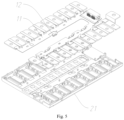
Fig. 1 is an overall structural diagram of a CCS assembly in the first embodiment of the present application; -
Fig. 2 is a partially enlarged diagram ofFig. 1 at A; -
Fig. 3 is a top view of a CCS assembly in the first embodiment of the present application; -
Fig. 4 is a partially enlarged diagram ofFig. 3 at B; -
Fig. 5 is an exploded view of a CCS assembly in the first embodiment of the present application. - Labels: 11 flexible circuit board; 12 collecting terminal; 121 temperature sensing member; 122 collection supporting part; 21 plastic supporting frame; 22 adhesive blocking part; 221 first lateral frame; 222 second lateral frame; 3 separation distance; 41 first positioning line; 42 second positioning line.
- In the description of the present application, it is to be noted that the terms "up", "down", "front", "back", "left", "right", "vertical", "horizontal", "top", "bottom", "inside", "outside" and other orientation or position relationships are based on the orientation or position relationships shown in the attached drawings. It is only intended to facilitate description and simplify operation, but not to indicate or imply that the referred device or element has a specific orientation, or is constructed and operated in a specific orientation. Therefore, they should not be construed as a limitation of the present application.
-
Flexible circuit board 11, also known as FPC, which provides good properties such as light weight, thin thickness, and good bendability, has been widely used in battery packs and battery products, enabling battery packs and battery products to provide more prominent advantages in terms of such as safety, light weight, and layout regularity. Typically, theflexible circuit board 11 is used in battery packs and battery products as a collecting harness for testing, collecting voltage and detecting temperature. - In the manufacturing process (such as pressing process) flow, due to the process parameters (such as temperature, humidity and time) in the manufacturing process is improperly configured or the coating of adhesive is uneven, it is easy to lead to the overflow of adhesive in the manufacturing process. In addition, factors such as excessive adhesive output and excessive pressure during processing may also lead to the abnormal problem of adhesive overflow.
- In view of the problem of adhesive overflow during the processing of
flexible circuit board 11 mentioned above, please refer toFig. 1 to Fig. 5 for details. Disclosed in the present application is a CCS assembly, including: - a
flexible circuit board 11, theflexible circuit board 11 being provided with acollecting terminal 12, thecollecting terminal 12 being used for collecting a temperature signal of a cell; and - a plastic supporting
frame 21, the plastic supportingframe 21 being provided with a temperature-sensing collecting zone, an edge of the temperature-sensing collecting zone being provided with anadhesive blocking part 22, in which theflexible circuit board 11 is mounted and fixed on the plastic supportingframe 21, and thecollecting terminal 12 is provided in an interior of theadhesive blocking part 22, thecollecting terminal 12 being connected to the plastic supportingframe 21 by adhesive. - In the present embodiment, a plastic supporting
frame 21 cooperating with theflexible circuit board 11 may better ensure the lightweight of the CCS assembly, and also enable the structure of the CCS assembly to be lighter, more cost-saving, and also improve the processing efficiency. When the CCS assembly is mounted and fixed on the battery pack, the temperature-sensing collecting zone is projected onto a surface of the corresponding cell to form temperature-sensing collecting points on the cell. Thermally conductive adhesive is poured on thecollecting terminal 12 to achieve the objective of thermal conductive connection between thecollecting terminal 12 and the cell. - On the one side, utilizing the good adhesive properties of the heat-conductive adhesive as well as the excellent moisture-proof and shock-resistant properties thereof, the
collecting terminal 12 is stably fixed on the corresponding cell, so as to avoid the risk of loosening between theflexible circuit board 11 and the cell. On the flip side, utilizing the thermal conductivity of the heat-conductive adhesive, the temperature of the cell may be steadily transferred to the collectingterminal 12 through the heat-conductive adhesive, thereby enabling the collectingterminal 12 to continuously collect the temperature signal of the cell. - It is to be noted that the adhesive is not limited to the heat-conductive adhesive mentioned above. Other adhesives that may achieve the thermal conductive connection between the
collecting terminal 12 and the cell are all may be used as adhesive for replacing the heat-conductive adhesive in the present embodiment. - Besides reducing the amount of adhesive of the heat-conductive adhesive, constrained by the adhesive blocking
part 22 mentioned above, the adhesive is rendered not to diffuse and flow over a large area towards a periphery of thecollecting terminal 12. When the amount of adhesive is excessive, the excess adhesive may be constrained in the interior of theadhesive blocking part 22, which solves the risk that the collectingterminal 12 of theflexible circuit board 11 is prone to overflow of adhesive during the process of applying adhesive. - As the essence of the present embodiment is that, as shown in
Fig. 3 and Fig. 4 for details, a separation distance 3 is provided between thecollecting terminal 12 and a side wall of theadhesive blocking part 22, in which the separation distance 3 is used to accommodate the excess adhesive, which reduces heat transfer from the plastic supportingframe 21 directly or indirectly to the collectingterminal 12 through the adhesive. - Specifically, part of the heat of the cell is transferred to the plastic supporting
frame 21, and then the plastic supportingframe 21 also possesses a certain amount of heat. When the amount of adhesive is excessive, the excess adhesive diffuses to the separation distance 3 so that a small amount of adhesive is in contact with theadhesive blocking part 22 or even no adhesive in contact with theadhesive blocking part 22, which avoids the problem of heat on the plastic supportingframe 21 aggregating to thecollecting terminal 12 through the adhesive, thereby leading to interference with the accurate collection of the temperature of the cell by thecollecting terminal 12. Further, under the cooperating action of theadhesive blocking part 22 and the separation distance 3, the problem of overflow of adhesive in the processing of theflexible circuit board 11 is solved, and the collecting accuracy of the collectingterminal 12 for the temperature of the cell is also effectively improved. - Unexpectedly, when the amount of adhesive is managed within a suitable range, the adhesive and the adhesive blocking
part 22 are also capable of blocking the transfer of heat from the adhesive blockingpart 22 to the collectingterminal 12 under the action of the separation distance 3. Therefore, in conjunction with the method of managing the amount of adhesive, it may highly effectively ensure that the collectingterminal 12 detects and collects the temperature of the cell with high accuracy. - As another solution of the present embodiment, please refer to
Fig. 1, Fig. 2 andFig. 3 for details. The adhesive blockingpart 22 includes two firstlateral frame 221 and two secondlateral frame 222; two firstlateral frame 221 are provided oppositely and two secondlateral frame 222 are provided oppositely; and two firstlateral frame 221 and two secondlateral frame 222 are enclosed in a square structure. - It is to be noted that each first
lateral frame 221 is connected to the adjacent secondlateral frame 222, which may not only ensure that the adhesive may not infiltrate out from the adhesive blockingpart 22 but may also effectively ensure an overall structural strength of the adhesive blockingpart 22. Admittedly, each lateral edge of the firstlateral frame 221 may also be in contact with a lateral edge of the secondlateral frame 222. Alternatively, a gap exists between the firstlateral frame 221 and the secondlateral frame 222. - Supplementarily, the separation distance 3 may be suitably increased in order to achieve that, in the case of an excessive amount of adhesive, the excess adhesive is not in contact with the first
lateral frame 221 or with the secondlateral frame 222, in which the size of the separation distance 3 is determined and adjusted according to the structural design of the plastic supportingframe 21 and the assembly requirements of the battery, and the size of the separation distance 3 is not limited hereby. - As an preferable solution of the present embodiment, please refer to
Fig. 1, Fig. 2 andFig. 3 for details. The adhesive blockingpart 22 includes a firstlateral frame 221 and a secondlateral frame 22, in which the firstlateral frame 221 and the secondlateral frame 222 are vertically distributed in an L shape, and the firstlateral frame 221 and the secondlateral frame 222 are both fixedly connected to theplastic supporting frame 21. - The first
lateral frame 221 is preferably connected to the secondlateral frame 222, which ensures that the adhesive may not infiltrate from the adhesive blockingpart 22, and also ensures an overall structural strength of the adhesive blockingpart 22. Admittedly, a lateral edge of the firstlateral frame 221 may also be in contact with a lateral edge of the secondlateral frame 222. Alternatively, a gap exists between the firstlateral frame 221 and the secondlateral frame 222. - In such a setup, it not only further reduces the material and mass of the adhesive blocking
part 22 and saves cost, but also simplifies the structure of the plastic supportingframe 21, rendering the structure of the plastic supportingframe 21 more simple and lightweight. More importantly, the area of wall thickness is canceled. Also, in the case of reducing the temperature-sensing collecting zone and/or the separation distance 3, heat of the plastic supportingframe 21 may be avoided to directly or indirectly transfer to the collectingterminal 12 causing a risk of interference with the detection/collection of the collectingterminal 12 by the heat of the plastic supportingframe 21. It is achieved that the size of the temperature-sensing collecting zone and theplastic supporting frame 21 is reduced to enable a more compact assembly of the collectingterminal 12 and the adhesive blockingpart 22, while ensuring a high accuracy of the collectingterminal 12 in collecting the temperature of the cell. - Further,
flexible circuit boards 11 provide a certain degree of flexibility. Assembly errors may occur when theflexible circuit board 11 and theplastic supporting frame 21 are assembled with each other. The collectingterminal 12 is prone to misalignment during assembly to the interior of the adhesive blockingpart 22, so that the separation distance 3 is not achieved between the collectingterminal 12 and the adhesive blockingpart 22, thereby causing the risk of overflow of adhesive due to inaccurate alignment of the collectingterminal 12. - Referring to
Fig. 2 andFig. 4 for details, an interior of the temperature sensing collecting-zone is also provided with afirst positioning line 41; thefirst positioning line 41 is extended in a length direction of theflexible circuit board 11; thefirst positioning line 41 is used as a first reference standard for assembling the collectingterminal 12 to the temperature-sensing collecting zone; and the collectingterminal 12 is assembled in the interior of the temperature sensing collecting-zone and is aligned with thefirst positioning line 41, so that the separation distance 3 is formed between the collectingterminal 12 and the adhesive blockingpart 22. - In the present embodiment, the first
lateral frame 221 of the adhesive blockingpart 22 is defined to extend in a length direction of theflexible circuit board 11, so the extension direction of the secondlateral frame 222 is perpendicular to a length direction of theflexible circuit board 11. Then, thefirst positioning line 41 mentioned above is parallel to the firstlateral frame 221, and a relative distance between thefirst positioning line 41 and the firstlateral frame 221 is equal to the separation distance 3. - Specifically, as shown in
Fig. 4 , when a collectingterminal 12 is assembled to an interior of the adhesive blockingpart 22, thefirst positioning line 41 is used as a first reference standard. A lateral edge of the collectingterminal 12 is aligned with thefirst positioning line 41 in a direction perpendicular to the temperature-sensing collecting zone, and a relative distance between the collectingterminal 12 and the firstlateral frame 221 is equal to the separation distance 3. - As can be seen from the above, under the action of the
first positioning line 41, the assembly accuracy of the collectingterminal 12 is improved, and the problem of inaccurate positioning of the collectingterminal 12 in the assembly process is eliminated, so as to avoid the problem of overflow of adhesive in the manufacturing process. Additionally, it also avoids the problem that the relative distance between the collectingterminal 12 and the firstlateral frame 221 is reduced due to the offset and misalignment of the collectingterminal 12 resulting in the heat transfer from the adhesive blockingpart 22 to the collectingterminal 12, and effectively ensures the accuracy of the detection and collection of the collectingterminal 12. - Supplementarily, the
first positioning line 41 may be provided on the temperature-sensing collecting zone by applying, or may be provided on the temperature-sensing collecting zone by engraving, or may be a protruding structure in the form of a long strip and integrally molded with the plastic supportingframe 21. - Additionally, referring to
Fig. 2 andFig. 4 for details, the interior of the temperature sensing collecting-zone is also provided with asecond positioning line 42; thesecond positioning line 42 is perpendicular to thefirst positioning line 41; thesecond positioning line 42 is used as a second reference standard for assembling the collectingterminal 12 to the temperature-sensing collecting zone; and the collectingterminal 12 is assembled in the interior of the temperature sensing collecting-zone and is aligned with thesecond positioning line 42, so that the separation distance 3 is formed between the collectingterminal 12 and the adhesive blockingpart 22. - Specifically, the
second positioning line 42 is parallel to the secondlateral frame 222, and a relative distance between thesecond positioning line 42 and the secondlateral frame 222 is equal to the separation distance 3. As shown inFig. 4 , when a collectingterminal 12 is assembled to an interior of the adhesive blockingpart 22, thesecond positioning line 42 is used as a second reference standard. A lateral edge of the collectingterminal 12 is aligned with thesecond positioning line 42 in a direction perpendicular to the temperature-sensing collecting zone, and a relative distance between the collectingterminal 12 and the secondlateral frame 222 is equal to the separation distance 3. - Therefore, under the action of the
second positioning line 42, the assembly accuracy of the collectingterminal 12 is improved, and the problem of inaccurate positioning of the collectingterminal 12 in the assembly process is eliminated, so as to avoid the problem of overflow of adhesive in the manufacturing process. Likewise, it also avoids the problem that the relative distance between the collectingterminal 12 and the secondlateral frame 222 is reduced due to the offset and misalignment of the collectingterminal 12 resulting in the heat transfer from the adhesive blockingpart 22 to the collectingterminal 12. - Also, under the combined function of the
first positioning line 41 and thesecond positioning line 42, the collectingterminal 12 may be precisely positioned in both the direction along the length of theflexible circuit board 11 and the direction perpendicular to the length of theflexible circuit board 11, so as to effectively ensure the assembly accuracy between the adhesive blockingpart 22 and the collectingterminal 12, thereby effectively ensuring that the collectingterminal 12 carries out a stable and accurate collection. - Supplementarily, the
second positioning line 42 may be provided on the temperature-sensing collecting zone by applying, or may be provided on the temperature-sensing collecting zone by engraving, or may be a protruding structure in the form of a long strip and integrally molded with the plastic supportingframe 21. - It is to be noted that the temperature-sensing collecting zone may be provided with only the
first positioning line 41 when the collectingterminal 12 is not provided with a secondlateral frame 222 in the direction of offsetting along the length of theflexible circuit board 11 of the plastic supportingframe 21. - Referring to
Fig. 2 for details, the collectingterminal 12 includes atemperature sensing member 121 and acollection supporting part 122, thetemperature sensing member 121 being fixedly connected to thecollection supporting part 122, thecollection supporting part 122 being fixedly connected to theflexible circuit board 11. Thetemperature sensing member 121 is preferably thermistor, admittedly, or may be other elements for detecting temperature, such as a temperature sensor. Thecollection supporting part 122 is made of a metal material with good thermal conductivity, such as aluminum and copper. Thetemperature sensing member 121 abuts the cell, so that thetemperature sensing member 121 may directly detect and collect the temperature of the cell, thereby achieving the objective that the collectingterminal 12 collects the temperature signal of the cell accurately and efficiently. - Further, referring to
Fig. 1 andFig. 3 for details, a plurality of the temperature sensing collecting-zones are provided on the plastic supporting frame 3 in a length direction of theflexible circuit board 11; an edge of each temperature sensing collecting-zone is provided with the adhesive blockingpart 22; a plurality of the collecting terminals are provided on theflexible circuit board 11; each collectingterminal 12 is provided corresponding to each adhesive blockingpart 22; and each collectingterminal 12 is provided in an interior of each adhesive blockingpart 22. - Specifically, a plurality of temperature-sensing collecting zones are evenly provided in a length direction of the
flexible circuit board 11. Alternatively, as shown inFig. 1 andFig. 3 , a plurality of temperature-sensing collecting zones are unevenly provided in a length direction of theflexible circuit board 11. Theadhesive blocking parts 22 may all be in an L-shaped structure, or may all be in a square-shaped structure. Admittedly, as shown inFig. 1 andFig. 3 , the adhesive blockingpart 22 may be a mix of L-shaped and square-shaped structures. Preferably, square-shapedadhesive blocking part 22 is provided on two ends of theflexible circuit board 11 in the length direction, and square-shapedadhesive blocking part 22 is provided on the middle part of theflexible circuit board 11. - By providing a plurality of temperature-sensing collecting zones on the
plastic supporting frame 21 and cooperating with a plurality of collectingterminals 12 of theflexible circuit board 11, a plurality of different cell surfaces of the battery pack are detected and collected, and the collection accuracy of the battery pack is further improved. - On the basis of a CCS assembly disclosed in the First Embodiment, disclosed by the inventor is also a battery module, the battery module includes:
- a battery pack; and
- a CCS assembly mentioned above, the CCS assembly being provided on the battery pack, and a collecting
terminal 12 of aflexible circuit board 11 being thermally conductively connected to the battery pack. - Specifically, the collecting
terminal 12 of theflexible circuit board 11 abuts the corresponding cell of the battery pack, and is fixed and heat-conducted by adhesive, in which the adhesive is preferably a heat-conductive adhesive. In such a setup, the collectingterminal 12 may collect the temperature of the cell effectively and directly, under the combined function of the separation distance 3 and the adhesive blockingpart 22, which effectively ensures the collection accuracy of the collectingterminal 12 on the temperature of the cell. - It is to be noted that a height of the collecting
terminal 12 is greater than that of the adhesive blockingpart 22. That is, the relative distance between the collectingterminal 12 for contacting and detecting the side of the cell and the temperature-sensing collecting zone is greater than a total height of the adhesive blockingpart 22, so that the collectingterminal 12 may abut the cell of the battery pack. Additionally, thetemperature sensing member 122 of the collectingterminal 12 is fixed to theplastic supporting frame 21 by foam adhesive. - Further, a plurality of collecting
terminals 12 are provided on theflexible circuit board 11, and a plurality of collectingterminals 12 are thermally conductive connected to a plurality of cells of the battery pack, so that a plurality of collecting points are provided on different positions on the battery pack to acquire temperature signals of different cells, which further improves the temperature collecting accuracy of the battery pack. - On the basis of a battery module disclosed in the Second Embodiment, disclosed by the inventor is also a battery pack, the battery pack including the battery module mentioned above.
- In the present embodiment, the temperature signal acquired form the
flexible circuit board 11 of the battery module is transferred to the battery management system (BMS) of the battery pack. Under the action of the adhesive blockingpart 22 of the plastic supportingframe 21 and the separation distance 3 between the collectingterminal 12 and the adhesive blockingpart 22, the battery management system may stably and accurately acquire the cell temperature of the battery pack so as to accurately monitor the operating condition of the cell, which ensures the operating stability and an optimal operating performance of the battery pack and a battery production adopted the battery pack.
Claims (12)
- ACCS assembly, comprising:a flexible circuit board (11), the flexible circuit board (11) being provided with a collecting terminal (12), the collecting terminal (12) being used for collecting a temperature signal of a cell; anda plastic supporting frame (21), the plastic supporting frame (21) being provided with a temperature-sensing collecting zone, an edge of the temperature-sensing collecting zone being provided with an adhesive blocking part (22), wherein the flexible circuit board (11) is mounted and fixed on the plastic supporting frame (21), and the collecting terminal (12) is provided in an interior of the adhesive blocking part (22), a separation distance (3) being formed between the collecting terminal (12) and a side wall of the adhesive blocking part (22).
- The CCS assembly according to claim 1, wherein the adhesive blocking part (22) comprises a first lateral frame (221) and a second lateral frame (222); the first lateral frame (221) and the second lateral frame (222) are vertically distributed in an L shape; and the first lateral frame (221) and the second lateral frame (222) are both fixedly connected to the plastic supporting frame (21).
- The CCS assembly according to claim 2, wherein the adhesive blocking part (22) comprises two first lateral frame (221) and two second lateral frame (222); two first lateral frame (221) are provided oppositely and two second lateral frame (222) are provided oppositely; and two first lateral frame (221) and two second lateral frame (222) are enclosed in a square structure.
- The CCS assembly according to claim 1, wherein an interior of the temperature-sensing collecting zone is also provided with a first positioning line (41); the first positioning line (41) is extended in a length direction of the flexible circuit board (11); and the collecting terminal (12) is assembled in the interior of the temperature-sensing collecting zone and is aligned with the first positioning line (41), so that the separation distance (3) is formed between the collecting terminal (12) and the adhesive blocking part (22).
- The CCS assembly according to claim 4, wherein the interior of the temperature-sensing collecting zone is also provided with a second positioning line (42); the second positioning line (42) is perpendicular to the first positioning line (41); and the collecting terminal (12) is assembled in the interior of the temperature-sensing collecting zone and is aligned with the second positioning line (42), so that the separation distance (3) is formed between the collecting terminal (12) and the adhesive blocking part (22).
- The CCS assembly according to any one of claims 1-5, wherein a plurality of the temperature-sensing collecting zones are provided on the plastic supporting frame (21) in a length direction of the flexible circuit board (11); an edge of each temperature-sensing collecting zone is provided with the adhesive blocking part (22); a plurality of the collecting terminals (12) are provided on the flexible circuit board (11); each collecting terminal (12) is provided corresponding to each adhesive blocking part (22); and each collecting terminal (12) is provided in an interior of each adhesive blocking part (22).
- The CCS assembly according to any one of claims 1-5, wherein the collecting terminal (12) comprises a temperature sensing member (121) and a collection supporting part (122), the temperature sensing member (121) being fixedly connected to the collection supporting part (122), the collection supporting part (122) being fixedly connected to the flexible circuit board (11).
- The CCS assembly according to claim 1, wherein thermally conductive adhesive is poured on the collecting terminal (12), used for thermally conductively connecting the collecting terminal (12) to the cell.
- A battery module, comprising:a battery pack; anda CCS assembly as claimed in any one of claims 1-8, the CCS assembly being provided on the battery pack, a collecting terminal (12) of a flexible circuit board (11) being thermally conductively connected to the battery pack.
- The battery module according to claim 9, wherein a plurality of the collecting terminals (12) are provided on the flexible circuit board (11), and a plurality of the collecting terminals (22) are thermally conductively connected to a plurality of cells of the battery pack.
- The battery module according to claim 9, wherein a height of the collecting terminal (12) is greater than that of the adhesive blocking part (22), so that the collecting terminal (12) abuts the cell of the battery pack.
- A battery pack, comprising a battery module as claimed in any one of claims 9-11.
Applications Claiming Priority (1)
| Application Number | Priority Date | Filing Date | Title |
|---|---|---|---|
| CN202320704342.6U CN219739032U (en) | 2023-03-31 | 2023-03-31 | CCS assembly, battery module and battery pack |
Publications (1)
| Publication Number | Publication Date |
|---|---|
| EP4439774A1 true EP4439774A1 (en) | 2024-10-02 |
Family
ID=88058196
Family Applications (1)
| Application Number | Title | Priority Date | Filing Date |
|---|---|---|---|
| EP23213167.2A Pending EP4439774A1 (en) | 2023-03-31 | 2023-11-29 | Ccs assembly, battery module and battery pack |
Country Status (3)
| Country | Link |
|---|---|
| EP (1) | EP4439774A1 (en) |
| CN (1) | CN219739032U (en) |
| WO (1) | WO2024197995A1 (en) |
Citations (3)
| Publication number | Priority date | Publication date | Assignee | Title |
|---|---|---|---|---|
| US20180175358A1 (en) * | 2016-12-19 | 2018-06-21 | Molex, Llc | Battery connection module and battery device |
| US20200275555A1 (en) * | 2019-02-26 | 2020-08-27 | GM Global Technology Operations LLC | Method of manufacturing battery module and interconnect board assembly with integrated pcb and flex circuit |
| EP3934004A1 (en) * | 2019-11-25 | 2022-01-05 | Contemporary Amperex Technology Co., Limited | Battery module, battery pack, and vehicle |
Family Cites Families (3)
| Publication number | Priority date | Publication date | Assignee | Title |
|---|---|---|---|---|
| CN217396257U (en) * | 2022-03-31 | 2022-09-09 | 湖北亿纬动力有限公司 | CCS assembly and battery module |
| CN218070143U (en) * | 2022-09-08 | 2022-12-16 | 上海轩邑新能源发展有限公司 | Temperature acquisition device and have its battery module |
| CN218586118U (en) * | 2022-10-20 | 2023-03-07 | 宁德时代新能源科技股份有限公司 | Battery pack, battery and power consumption device |
-
2023
- 2023-03-31 CN CN202320704342.6U patent/CN219739032U/en active Active
- 2023-04-18 WO PCT/CN2023/088840 patent/WO2024197995A1/en not_active Ceased
- 2023-11-29 EP EP23213167.2A patent/EP4439774A1/en active Pending
Patent Citations (3)
| Publication number | Priority date | Publication date | Assignee | Title |
|---|---|---|---|---|
| US20180175358A1 (en) * | 2016-12-19 | 2018-06-21 | Molex, Llc | Battery connection module and battery device |
| US20200275555A1 (en) * | 2019-02-26 | 2020-08-27 | GM Global Technology Operations LLC | Method of manufacturing battery module and interconnect board assembly with integrated pcb and flex circuit |
| EP3934004A1 (en) * | 2019-11-25 | 2022-01-05 | Contemporary Amperex Technology Co., Limited | Battery module, battery pack, and vehicle |
Also Published As
| Publication number | Publication date |
|---|---|
| CN219739032U (en) | 2023-09-22 |
| WO2024197995A1 (en) | 2024-10-03 |
Similar Documents
| Publication | Publication Date | Title |
|---|---|---|
| US12519148B2 (en) | Battery module, battery pack, and vehicle | |
| CN112151703B (en) | battery module | |
| EP3965210A1 (en) | Battery module and device | |
| US20180045576A1 (en) | Temperature measuring apparatus, electrical assembly and battery pack | |
| US20220059882A1 (en) | Battery module and electric device | |
| CN216488417U (en) | A collection structure and battery module of FFC and blister tray integrated CCS | |
| CN104011518B (en) | Infrared sensor and infrared sensing device | |
| CN207116634U (en) | Battery modules | |
| CN207183457U (en) | Battery modules | |
| CN210221318U (en) | Connecting component with temperature detection device | |
| US11652244B2 (en) | Battery module and apparatus | |
| EP4239783A1 (en) | Battery connection module | |
| WO2025066191A1 (en) | Temperature collection device, ccs assembly, and battery module | |
| CN219739032U (en) | CCS assembly, battery module and battery pack | |
| CN211090150U (en) | Circuit board structure and lithium ion battery structure comprising same | |
| CN205985249U (en) | Batteries of electric vehicle module temperature detect structure | |
| WO2025108499A1 (en) | Insulating component, acquisition assembly, battery module and battery pack | |
| CN219269158U (en) | Circuit board assembly and battery pack | |
| EP4485617A1 (en) | Cells contact system, battery, and electric vehicle | |
| CN118248604A (en) | Tray module | |
| CN219810557U (en) | Detection device, equipment, rechargeable battery pack, energy storage module and vehicle | |
| CN213242507U (en) | Multifunctional wafer protrusion detection module | |
| CN214750681U (en) | Tool for detecting LED circuit board | |
| CN213340650U (en) | A collection device and battery module | |
| CN213932891U (en) | Temperature detection assembly and electronic equipment |
Legal Events
| Date | Code | Title | Description |
|---|---|---|---|
| PUAI | Public reference made under article 153(3) epc to a published international application that has entered the european phase |
Free format text: ORIGINAL CODE: 0009012 |
|
| STAA | Information on the status of an ep patent application or granted ep patent |
Free format text: STATUS: EXAMINATION IS IN PROGRESS |
|
| 17P | Request for examination filed |
Effective date: 20231129 |
|
| AK | Designated contracting states |
Kind code of ref document: A1 Designated state(s): AL AT BE BG CH CY CZ DE DK EE ES FI FR GB GR HR HU IE IS IT LI LT LU LV MC ME MK MT NL NO PL PT RO RS SE SI SK SM TR |