EP4439740A1 - Electrode catalyst including iridium oxide nanosheet as catalytic promoter - Google Patents
Electrode catalyst including iridium oxide nanosheet as catalytic promoter Download PDFInfo
- Publication number
- EP4439740A1 EP4439740A1 EP22898216.1A EP22898216A EP4439740A1 EP 4439740 A1 EP4439740 A1 EP 4439740A1 EP 22898216 A EP22898216 A EP 22898216A EP 4439740 A1 EP4439740 A1 EP 4439740A1
- Authority
- EP
- European Patent Office
- Prior art keywords
- nanosheet
- iro
- catalyst
- reversal
- electrode
- Prior art date
- Legal status (The legal status is an assumption and is not a legal conclusion. Google has not performed a legal analysis and makes no representation as to the accuracy of the status listed.)
- Withdrawn
Links
Images




Classifications
-
- H—ELECTRICITY
- H01—ELECTRIC ELEMENTS
- H01M—PROCESSES OR MEANS, e.g. BATTERIES, FOR THE DIRECT CONVERSION OF CHEMICAL ENERGY INTO ELECTRICAL ENERGY
- H01M4/00—Electrodes
- H01M4/86—Inert electrodes with catalytic activity, e.g. for fuel cells
- H01M4/90—Selection of catalytic material
-
- H—ELECTRICITY
- H01—ELECTRIC ELEMENTS
- H01M—PROCESSES OR MEANS, e.g. BATTERIES, FOR THE DIRECT CONVERSION OF CHEMICAL ENERGY INTO ELECTRICAL ENERGY
- H01M4/00—Electrodes
- H01M4/86—Inert electrodes with catalytic activity, e.g. for fuel cells
-
- H—ELECTRICITY
- H01—ELECTRIC ELEMENTS
- H01M—PROCESSES OR MEANS, e.g. BATTERIES, FOR THE DIRECT CONVERSION OF CHEMICAL ENERGY INTO ELECTRICAL ENERGY
- H01M4/00—Electrodes
- H01M4/86—Inert electrodes with catalytic activity, e.g. for fuel cells
- H01M4/90—Selection of catalytic material
- H01M4/9016—Oxides, hydroxides or oxygenated metallic salts
-
- H—ELECTRICITY
- H01—ELECTRIC ELEMENTS
- H01M—PROCESSES OR MEANS, e.g. BATTERIES, FOR THE DIRECT CONVERSION OF CHEMICAL ENERGY INTO ELECTRICAL ENERGY
- H01M4/00—Electrodes
- H01M4/86—Inert electrodes with catalytic activity, e.g. for fuel cells
- H01M4/90—Selection of catalytic material
- H01M4/92—Metals of platinum group
-
- H—ELECTRICITY
- H01—ELECTRIC ELEMENTS
- H01M—PROCESSES OR MEANS, e.g. BATTERIES, FOR THE DIRECT CONVERSION OF CHEMICAL ENERGY INTO ELECTRICAL ENERGY
- H01M4/00—Electrodes
- H01M4/86—Inert electrodes with catalytic activity, e.g. for fuel cells
- H01M4/90—Selection of catalytic material
- H01M4/92—Metals of platinum group
- H01M4/921—Alloys or mixtures with metallic elements
-
- H—ELECTRICITY
- H01—ELECTRIC ELEMENTS
- H01M—PROCESSES OR MEANS, e.g. BATTERIES, FOR THE DIRECT CONVERSION OF CHEMICAL ENERGY INTO ELECTRICAL ENERGY
- H01M4/00—Electrodes
- H01M4/86—Inert electrodes with catalytic activity, e.g. for fuel cells
- H01M4/90—Selection of catalytic material
- H01M4/92—Metals of platinum group
- H01M4/925—Metals of platinum group supported on carriers, e.g. powder carriers
-
- H—ELECTRICITY
- H01—ELECTRIC ELEMENTS
- H01M—PROCESSES OR MEANS, e.g. BATTERIES, FOR THE DIRECT CONVERSION OF CHEMICAL ENERGY INTO ELECTRICAL ENERGY
- H01M4/00—Electrodes
- H01M4/86—Inert electrodes with catalytic activity, e.g. for fuel cells
- H01M4/90—Selection of catalytic material
- H01M4/92—Metals of platinum group
- H01M4/925—Metals of platinum group supported on carriers, e.g. powder carriers
- H01M4/926—Metals of platinum group supported on carriers, e.g. powder carriers on carbon or graphite
-
- H—ELECTRICITY
- H01—ELECTRIC ELEMENTS
- H01M—PROCESSES OR MEANS, e.g. BATTERIES, FOR THE DIRECT CONVERSION OF CHEMICAL ENERGY INTO ELECTRICAL ENERGY
- H01M8/00—Fuel cells; Manufacture thereof
- H01M8/10—Fuel cells with solid electrolytes
-
- H—ELECTRICITY
- H01—ELECTRIC ELEMENTS
- H01M—PROCESSES OR MEANS, e.g. BATTERIES, FOR THE DIRECT CONVERSION OF CHEMICAL ENERGY INTO ELECTRICAL ENERGY
- H01M8/00—Fuel cells; Manufacture thereof
- H01M8/10—Fuel cells with solid electrolytes
- H01M2008/1095—Fuel cells with polymeric electrolytes
-
- Y—GENERAL TAGGING OF NEW TECHNOLOGICAL DEVELOPMENTS; GENERAL TAGGING OF CROSS-SECTIONAL TECHNOLOGIES SPANNING OVER SEVERAL SECTIONS OF THE IPC; TECHNICAL SUBJECTS COVERED BY FORMER USPC CROSS-REFERENCE ART COLLECTIONS [XRACs] AND DIGESTS
- Y02—TECHNOLOGIES OR APPLICATIONS FOR MITIGATION OR ADAPTATION AGAINST CLIMATE CHANGE
- Y02E—REDUCTION OF GREENHOUSE GAS [GHG] EMISSIONS, RELATED TO ENERGY GENERATION, TRANSMISSION OR DISTRIBUTION
- Y02E60/00—Enabling technologies; Technologies with a potential or indirect contribution to GHG emissions mitigation
- Y02E60/30—Hydrogen technology
- Y02E60/50—Fuel cells
Definitions
- the present invention relates to an electrode catalyst including an iridium oxide nanosheet as a promoter and exhibiting high performance as a reversal-resistant anode catalyst in fuel cells.
- a polymer electrolyte fuel cell (abbreviated as "PEFC") is expected to be a power source for vehicles with low carbon emissions and high energy conversion efficiency, and development is underway to achieve higher performance.
- PEFC polymer electrolyte fuel cell
- a particularly recent development issue is the problem of rapid catalyst degradation when a PEFC enters a reversal state. For example, in cold climates, water in the cell may freeze, causing flow path blockage and leading to shortage of hydrogen fuel. When this happens, the original anode undergoes a cathodic reaction, the cathode undergoes an anodic reaction, and the cell voltage turns to a negative value (cell reversal). When fuel is depleted in the anode, an anode potential rises above 1.5 V (cell reversal state) and the carbon in the carrier is severely oxidized, leading to performance degradation.
- Patent Documents 1 and 2 are related applications by the present inventors, and Non-Patent Documents 1 and 2 are references that will be cited in examples described below.
- the present invention has been made to solve the above-described problems, and an object thereof is to provide an electrode catalyst exhibiting high performance as a reversal-resistant anode catalyst in fuel cells.
- An electrode catalyst according to the present invention is a composite catalyst obtained by mixing an iridium oxide (IrO 2 ) nanosheet with a Pt/C (platinum-supported carbon) catalyst as a promoter.
- the electrode catalyst is constituted by a composite catalyst obtained by mixing an IrO 2 nanosheet with a Pt/C catalyst as a promoter, and thus exhibits high performance as a reversal-resistant anode catalyst for fuel cells.
- a composite catalyst obtained by mixing an IrO 2 nanosheet with a Pt/C catalyst as a promoter and thus exhibits high performance as a reversal-resistant anode catalyst for fuel cells.
- a weight ratio (percentage) of the IrO 2 nanosheet to a sum of the Pt/C and the IrO 2 nanosheet is within a range of 1% or more and 26% or less.
- a Pt:Ir (atomic ratio) constituting the composite catalyst is within a range of 1.5:1 to 50:1.
- an electrode catalyst exhibiting high performance as a reversal-resistant anode catalyst in fuel cells.
- An electrode catalyst according to the present invention is a composite catalyst obtained by mixing an iridium oxide (IrO 2 ) nanosheet with a Pt/C (platinum-supported carbon) catalyst as a promoter. This way, the electrode catalyst was found to exhibit high performance as a reversal-resistant anode catalyst for fuel cells. It should be noted that, although use of iridium, iridium oxide nanoparticles, and the like as a promoter has been known, there have been no examples of mixing an iridium oxide nanosheet as a promoter, and this is promising as a new electrode catalyst.
- An iridium oxide nanosheet is a nano-order iridium oxide single-crystal sheet having a thickness of about 0.4 nm or more and 3 nm or less.
- This iridium oxide nanosheet is produced by, as described in the experimental examples below, first causing an alkylammonium or an alkylamine to react with a layered iridate to form an alkylammonium - layered iridate intercalation compound, and subsequently mixing the alkylammonium - layered iridate intercalation compound with a solvent such as water to obtain an iridium oxide nanosheet dispersed liquid (dark blue dispersed solution).
- a solvent such as water
- the layered iridate salt is synthesized, the layered iridate is synthesized from the layered iridate salt, and the iridium oxide nanosheet is obtained from the layered iridate.
- Iridium oxide particles and iridium oxide nanosheets have been used as electrode catalysts of dimensionally stable electrodes for electrolysis, chlorine generation, metal ion separation, and the like, but there are no examples of using a composite catalyst mixed as a promotor of a Pt/C catalyst as a reversal-resistant anode catalyst for fuel cells.
- a Pt:Ir (atomic ratio) constituting the composite catalyst is preferably within a range of 1.5:1 to 50:1, and such a composite catalyst can be preferably used as a reversal-resistant anode catalyst for fuel cells.
- the Pt/C applied may be the conventionally known Pt/C described in Japanese Laid-Open Patent Application Publication No. 2011-134477 , for example.
- HCl hydrochloric acid
- IPA 2-propanol
- TSAOH 10% tetrabutylammonium hydroxide
- HNO 3 nitric acid
- K 2 CO 3 potassium carbonate
- ethanol methanol
- IrO 2 iridium oxide
- 0.1 MHClO 4 was prepared by diluting 70% perchloric acid (HClO 4 ).
- a dispersed liquid of 5-wt% Nafion (trademark) was also prepared with a commercial reagent.
- a Pt/C catalyst containing 46.3-wt% Pt was also prepared with a commercial product.
- IrO 2 nanosheet was fabricated by chemical exfoliation of layered iridium oxide in accordance with the method described in Patent Documents 1 and 2.
- a 0.53 mg/L of IrO 2 nanosheet/TBAOH colloid (referred to as "IrO 2 nanosheet dispersed liquid") obtained by centrifuging was used in this experiment.
- the composite catalyst was obtained by directly mixing the Pt/C catalyst and the IrO 2 nanosheet. 18.5 mg of the Pt/C was dispersed in a 75% IPA solution to obtain a Pt/C dispersed liquid, and 5 mL of the IrO 2 nanosheet dispersed liquid was added thereto and mixed well. Subsequently, the mixture was heated to 80°C for three hours to obtain a dry powder.
- This composite catalyst consisted of 74-wt% Pt/C and 26-wt% IrO 2 nanosheet, and is herein referred to as a "Pt/C-IrO 2 nanosheet-26.”
- the electrochemical characteristics were evaluated using a rotating disk electrode (manufactured by Nikko Keisoku, model name: SC-5) connected to a potentiostat (manufactured by Hokuto Denko, model name: HZ-7000).
- a three-electrode cell carbon fiber was used as a counter electrode and a reversible hydrogen electrode (RHE) was used as a reference electrode. All electrochemical measurements were performed in 0.1 MHClO 4 degassed with N 2 , except for hydrogen oxidation reaction (HOR) activity measurements.
- a working electrode was fabricated by using a mirror-polished glassy carbon (GC) electrode (6 mm in diameter) as a collector and dripping a predetermined amount of electrode catalyst onto the electrode. Next, the diluted Nafion solution was added as a binding material. The amount of catalyst added on the GC was set to 17.3 ⁇ g/cm 2 .
- GC mirror-polished glassy carbon
- OER oxygen evolution reaction
- Fig. 1 (a) The procedure for the reversal resistance test is shown in Fig. 1 (a) .
- the test temperature was set to 60°C
- the rotating speed of the electrode was set to 1600 rpm
- the potential sweep rate was set to 20 mV/sec
- the potential scanning range was set to 0.05 V to 1.2 V.
- Data of the third cycle was used to calculate an electrochemical surface area (ECSA).
- CP first chronopotentiometry test
- CP-1 the first chronopotentiometry test at a current density of 35.3 ⁇ A/cm 2 and a holding time of 20 minutes was performed as the first step of the reversal resistance test.
- the current densities were increased sequentially to 106 ⁇ A/cm 2 , 176 ⁇ A/cm 2 , 247 ⁇ A/cm 2 , and 353 ⁇ A/cm 2 and set as CP-2, CP-3, CP-4, and CP-5 in that order, respectively, and the corresponding ESCA after each CP was also recorded.
- the apparent HOR activity was evaluated by a chronoamperometric (CA) curve.
- the current value after 40 minutes at a low potential polarization of 20 mV (RHE) was set.
- the HOR mass activity (MAk) was calculated from the active dominant current by varying the electrode rotating speed of the rotating disk electrode and using the Koutecky-Levich equation.
- the potential range was set to -0.08 V to 0.5 V (RHE), and linear sweep voltammetry (LSV) was performed at rotating speeds of 400 rpm, 800 rpm, 1200 rpm, 1600 rpm, 2200 rpm, and 2500 rpm.
- a flowchart shown in Fig. 1 (b) is a procedure of the reversal resistance test combined with an HOR activity evaluation.
- the HOR activity was measured before and after the CP, varying the current density to 16 ⁇ A/cm 2 (CP-1), 36 ⁇ A/cm 2 (CP-2), 60 ⁇ A/cm 2 (CP-3), and 84 ⁇ A/cm 2 (CP-4).
- the OER starting potentials of the Pt/C catalyst and the Pt/C-IrO 2 nanosheet-26 were 1.51 V (RHE) and 1.43 V (RHE), respectively.
- the Pt/C-IrO 2 nanosheet catalysts all exhibited similar OER starting potentials in the vicinity of 1.43 V (RHE), regardless of IrO 2 content.
- Fig. 3 shows the LSV data of each sample.
- the current density at 1.5 V (RHE) was selected as an indicator of OER activity.
- the OER activities of the IrO 2 (nanosheet; reference sign c in Fig. 3 ) and the Pt/C-IrO 2 nanosheet-26 (reference sign b in Fig. 3 ) were 0.25 mA/cm 2 and 5.83 mA/cm 2 , respectively.
- the exhibited activity of the composite catalyst including 26-wt% IrO 2 nanosheets was about 20 times higher than that of the IrO 2 nanosheet.
- the activity of IrO 2 nanosheet-supported carbon being higher than that of an unsupported IrO 2 nanosheet is considered to reflect a difference in a dispersibility of the IrO 2 .
- the content of the expensive and rare IrO 2 is as low as possible.
- the OER activity of a Pt/C-IrO 2 nanosheet-5 (reference sign d in Fig. 3 ) was 4.38 mA/cm 2 .
- the reason for the current density being lower than that of the Pt/C-IrO 2 nanosheet-26 is the lower amount of the IrO 2 nanosheet. Eighty percent of the current density was obtained with one-fifth of the amount of the IrO 2 nanosheet, which means that the dispersibility of the IrO 2 nanosheet was improved and a surface utilization rate thereof was further enhanced.
- the OER activity of the Pt/C-IrO 2 nanosheet-5 (reference sign d in Fig. 3 ) is 18 times greater than that of the Pt/C (reference sign a in Fig. 3 ). All of the results described above indicate that the IrO 2 nanosheet acts as an OER promoter.
- the composite catalyst including the IrO 2 nanosheet functioning as a promoter of OER activity was evaluated for its function as a reversal-resistant anode catalyst of PEFC anodes in consideration of its assistance in suppressing carbon oxidation during fuel cell operation under fuel shortage conditions.
- the CPs (35.3 ⁇ A/cm 2 , 106 ⁇ A/cm 2 , 176 ⁇ A/cm 2 , 247 ⁇ A/cm 2 , and 353 ⁇ A/cm 2 ) were set, and the CV was measured before and after each CP test and evaluated as a change in ECSA.
- the results of the CP at each current density for the Pt/C catalyst are shown in Fig. 4 (a)
- the results of the CV after each constant current CP are shown in Fig. 4 (b) .
- CP results shown in Fig. 4 (a) indicate that, in the Pt/C, each potential rise in a case in which the currents of CP-1 (35.3 ⁇ A/cm 2 : reference sign a in Fig. 4 (a) ) and CP-2 (106 ⁇ A/cm 2 : reference sign b in Fig. 4 (a) ) were applied was less than 1.5 V (RHE).
- the ECSA of the Pt/C changed to 66.6 m 2 /g and 57.3 m 2 /g, respectively, and finally decreased to 48.9 m 2 /g (55% of unused Pt) after CP-5.
- the behavior of the change to the first plateau (1.5 V (RHE)) and the second plateau (1.65 V (RHE)) is similar to the cell voltage rise behavior observed in fuel cell single cells under fuel shortage conditions, where the first plateau is caused by a water electrolysis reaction (OER) and the second plateau is caused by a carbon oxidation reaction.
- OER water electrolysis reaction
- Fig. 5 (a) The results of the reversal resistance test of the Pt/C-IrO 2 nanosheet-5 composite catalyst are shown in Fig. 5 (a) .
- CP-5 353 ⁇ A/cm 2 : reference code e in Fig. 5 (a)
- the CV results measured after each CP step are shown in Fig. 5 (b) .
- the changes in the EDL region and quinone/hydroquinone redox peaks are small, clearly indicating that the oxidative degradation of the carrier carbon is suppressed by forming a composite with the IrO 2 nanosheet.
- the CV results after CP are shown in Fig. 6 (b) and Fig. 6 (d) .
- the ECSA of the Pt/C-IrO 2 nanosheet-3 decreased from 78.7 m 2 /g initially to 33.6 m 2 /g after the CP (58% reduction).
- the ECSA decreased from 94.7 m 2 /g to 46.5 m 2 /g (51% reduction).
- an EDL region and quinone/hydroquinone redox peaks also appeared.
- thicker quinone/hydroquinone redox peaks began to appear after CP-5.
- HOR was implemented on the Pt/C and the Pt/C-IrO 2 nanosheet-5 by CA (under hydrogen saturated conditions, 20 mV (RHE)) after the reversal resistance test, and MAapp and MAk were calculated.
- the CA of each catalyst is shown in Fig. 7 (a) and Fig. 7 (b) .
- the initial MAapp was 270 A/g, which is similar to the value described in Non-Patent Document 1. After the reversal resistance test, the MAapp decreased to 50 A/g (80% reduction). On the other hand, in the case of the Pt/C-IrO 2 nanosheet-5, the initial MAapp was 260 A/g and the MAapp after the reversal resistance test was 125 A/g (50% reduction).
- the LSV was measured at various rotating speeds using a rotating electrode, and the HOR activity (MAk) was determined using the activation dominant current from the Koutecky-Levich (K-L) plot at 20 mV (RHE). The respective calculations were performed, and the K-L plots are shown in Fig. 8 (a) and Fig. 8 (b) .
- the MAk of unused Pt/C was 940 A/g and was 345 A/g after the reversal resistance test (73% reduction).
- the initial MAk of the Pt/C-IrO 2 nanosheet-5 was 910 A/g, and was 497 A/g after the reversal resistance test (55% reduction). It should be noted that this rate of change is consistent with the change in ECSA after the reversal resistance test.
Landscapes
- Chemical & Material Sciences (AREA)
- Chemical Kinetics & Catalysis (AREA)
- Electrochemistry (AREA)
- General Chemical & Material Sciences (AREA)
- Engineering & Computer Science (AREA)
- Materials Engineering (AREA)
- Life Sciences & Earth Sciences (AREA)
- Manufacturing & Machinery (AREA)
- Sustainable Development (AREA)
- Sustainable Energy (AREA)
- Catalysts (AREA)
- Inert Electrodes (AREA)
- Fuel Cell (AREA)
Abstract
Description
- The present invention relates to an electrode catalyst including an iridium oxide nanosheet as a promoter and exhibiting high performance as a reversal-resistant anode catalyst in fuel cells.
- A polymer electrolyte fuel cell (abbreviated as "PEFC") is expected to be a power source for vehicles with low carbon emissions and high energy conversion efficiency, and development is underway to achieve higher performance. A particularly recent development issue is the problem of rapid catalyst degradation when a PEFC enters a reversal state. For example, in cold climates, water in the cell may freeze, causing flow path blockage and leading to shortage of hydrogen fuel. When this happens, the original anode undergoes a cathodic reaction, the cathode undergoes an anodic reaction, and the cell voltage turns to a negative value (cell reversal). When fuel is depleted in the anode, an anode potential rises above 1.5 V (cell reversal state) and the carbon in the carrier is severely oxidized, leading to performance degradation.
- It should be noted that
Patent Documents Non-Patent Documents -
- Patent Document 1:
Japanese Laid-Open Patent Application Publication No. 2015-171966 - Patent Document 2:
Japanese Laid-Open Patent Application Publication No. 2017-141158 -
- Non-Patent Document 1: G. Shi, H. Yano, D. A. Tryk, A. Iiyama, and H. Uchida, ACS Catal., 7, 267 (2017). doi: 10. 1021/acscatal. 6b02794
- Non-Patent Document 2: G. Shi, D. A. Tryk, T. Iwataki, H. Yano, M. Uchida, A. Iiyama, and H. Uchida, J. Mater. Chem. A, 8, 1091 (2020). doi: 10. 1039/C9TA12023H
- As described above, when the hydrogen, which is fuel, is depleted when the fuel cell stops working and oxygen crosses over to the anode, the anode potential becomes high (cell reversal state), resulting in degradation of the electrode catalyst. This is a cell reversal reaction in which the original hydrogen electrode reacts as an oxygen electrode, and the development of a reversal-resistant anode catalyst (also referred to as a "fuel shortage-resistant anode") that suppresses this reaction is desired.
- The present invention has been made to solve the above-described problems, and an object thereof is to provide an electrode catalyst exhibiting high performance as a reversal-resistant anode catalyst in fuel cells.
- An electrode catalyst according to the present invention is a composite catalyst obtained by mixing an iridium oxide (IrO2) nanosheet with a Pt/C (platinum-supported carbon) catalyst as a promoter.
- According to this invention, the electrode catalyst is constituted by a composite catalyst obtained by mixing an IrO2 nanosheet with a Pt/C catalyst as a promoter, and thus exhibits high performance as a reversal-resistant anode catalyst for fuel cells. It should be noted that, although use of iridium, iridium oxide nanoparticles, and the like as a promoter has been known, there have been no examples of mixing an IrO2 nanosheet as a promoter, and this is promising as a new electrode catalyst.
- In the electrode catalyst according to the present invention, a weight ratio (percentage) of the IrO2 nanosheet to a sum of the Pt/C and the IrO2 nanosheet is within a range of 1% or more and 26% or less.
- In the electrode catalyst according to the present invention, a Pt:Ir (atomic ratio) constituting the composite catalyst is within a range of 1.5:1 to 50:1.
- According to the present invention, it is possible to provide an electrode catalyst exhibiting high performance as a reversal-resistant anode catalyst in fuel cells.
-
-
Fig. 1 is a flowchart of a reversal resistance test, (a) showing a procedure of the reversal resistance test, and (b) showing a procedure of the reversal resistance test combined with a hydrogen oxidation reaction (HOR) activity evaluation. -
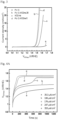
Fig. 2 shows linear sweep voltammetry (LSV) results of (a) a Pt/C catalyst and (b) a Pt/C-IrO2 nanosheet-26. -
Fig. 3 shows the LSV data of each sample. -
Fig. 4 (a) shows the results of a chronopotentiometry (CP) test simulating cell reversal of the Pt/C catalyst, andFig. 4 (b) shows the results of cyclic voltammetry (CV) test after implementation of the CP at various currents. -
Fig. 5 (a) shows the results of a CP test simulating cell reversal of a Pt/C-IrO2 nanosheet-5, andFig. 5 (b) shows the results of CV test after implementation of the CP at various currents. -
Fig. 6 (a) shows the results of a CP test of a Pt/C-IrO2 nanosheet-3 at each set current, andFig. 6 (b) shows the results of CV test after implementation of the CP at various currents.Fig. 6 (c) shows the results of a CP test of a Pt/C-IrO2 nanosheet-1 at each set current, andFig. 6 (b) shows the results of CV test after implementation of the CP at various currents. -
Fig. 7 (a) is a low-potential polarization curve (chronoamperometric (CA) curve) at 20 mV (RHE) for Pt/C, andFig. 7 (b) is a CA plot at 20 mV (RHE) of the Pt/C-IrO2 nanosheet-5. -
Fig. 8 shows Koutecky-Levich (K-L) plots at 20 mV (RHE) obtained from LSV data implemented at different rotating speeds, (a) being the results of the Pt/C and (b) being the results of the Pt/C-IrO2 nanosheet-5 before and after the reversal resistance test. -
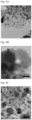
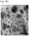
Fig. 9 (a) is a transmission electron microscope (TEM) image of unused Pt/C andFig. 9 (b) is a TEM image of the Pt/C after the test.Fig. 9 (c) is a TEM image of an unused Pt/C-IrO2 nanosheet-5 andFig. 9 (d) is a TEM image of the Pt/C-IrO2 nanosheet-5 after the test. - The following describes in detail an electrode catalyst according to the present invention. The present invention, however, is not limited to the following description, within the range included in the technical scope thereof.
- An electrode catalyst according to the present invention is a composite catalyst obtained by mixing an iridium oxide (IrO2) nanosheet with a Pt/C (platinum-supported carbon) catalyst as a promoter. This way, the electrode catalyst was found to exhibit high performance as a reversal-resistant anode catalyst for fuel cells. It should be noted that, although use of iridium, iridium oxide nanoparticles, and the like as a promoter has been known, there have been no examples of mixing an iridium oxide nanosheet as a promoter, and this is promising as a new electrode catalyst.
- An iridium oxide nanosheet (IrO2 nanosheet) is a nano-order iridium oxide single-crystal sheet having a thickness of about 0.4 nm or more and 3 nm or less. This iridium oxide nanosheet is produced by, as described in the experimental examples below, first causing an alkylammonium or an alkylamine to react with a layered iridate to form an alkylammonium - layered iridate intercalation compound, and subsequently mixing the alkylammonium - layered iridate intercalation compound with a solvent such as water to obtain an iridium oxide nanosheet dispersed liquid (dark blue dispersed solution). It should be noted that while various materials can be used as the alkylammonium or the alkylamine, tetrabutylammonium or the like, for example, can be preferably used.
- In the present invention, the layered iridate salt is synthesized, the layered iridate is synthesized from the layered iridate salt, and the iridium oxide nanosheet is obtained from the layered iridate. Iridium oxide particles and iridium oxide nanosheets have been used as electrode catalysts of dimensionally stable electrodes for electrolysis, chlorine generation, metal ion separation, and the like, but there are no examples of using a composite catalyst mixed as a promotor of a Pt/C catalyst as a reversal-resistant anode catalyst for fuel cells.
- A Pt:Ir (atomic ratio) constituting the composite catalyst is preferably within a range of 1.5:1 to 50:1, and such a composite catalyst can be preferably used as a reversal-resistant anode catalyst for fuel cells. It should be noted that the Pt/C applied may be the conventionally known Pt/C described in
Japanese Laid-Open Patent Application Publication No. 2011-134477 - In the following experiments, the present invention will be more specifically described.
- Commercial reagents were prepared for hydrochloric acid (HCl), 2-propanol (IPA), a 10% tetrabutylammonium hydroxide (TBAOH) solution, nitric acid (HNO3), potassium carbonate (K2CO3), ethanol, methanol, and iridium (IV) oxide (IrO2), respectively. 0.1 MHClO4 was prepared by diluting 70% perchloric acid (HClO4). A dispersed liquid of 5-wt% Nafion (trademark) was also prepared with a commercial reagent. A Pt/C catalyst containing 46.3-wt% Pt was also prepared with a commercial product.
- An IrO2 nanosheet was fabricated by chemical exfoliation of layered iridium oxide in accordance with the method described in
Patent Documents - In this experiment, composite catalysts fabricated with different proportions of the IrO2 nanosheet were prepared to study the optimal composite catalyst. The ratio of the Pt/C dispersed liquid to the IrO2 nanosheet dispersed liquid was arbitrarily varied. Table 1 shows the parameters of all composite catalysts synthesized in this experiment. Each composite catalyst was synthesized in the same way as that of the Pt/C-IrO2 nanosheet-26.
[Table 1] Name Pt/KB source solution IrO2ns/TBAOH colloid Resulted Pt:Ir02ns atomic ratio Resluted Ir0 2ns wt.°k Pt/KB- Ir02ns-26 10 ml 5 ml 3:2 26 Pt/KB-Ir02ns-15 10 ml 2.5 ml 3:1 15 Pt/KB-Ir02ns-5 10 ml 0.75 ml 10:1 5 Pt/KB-Ir02ns-3 10 ml 0.43 ml 17.6:1 3 Pt/KB-Ir02ns-1 10 ml 0.15 ml 50:1 1 - The electrochemical characteristics were evaluated using a rotating disk electrode (manufactured by Nikko Keisoku, model name: SC-5) connected to a potentiostat (manufactured by Hokuto Denko, model name: HZ-7000). In a three-electrode cell, carbon fiber was used as a counter electrode and a reversible hydrogen electrode (RHE) was used as a reference electrode. All electrochemical measurements were performed in 0.1 MHClO4 degassed with N2, except for hydrogen oxidation reaction (HOR) activity measurements.
- A working electrode was fabricated by using a mirror-polished glassy carbon (GC) electrode (6 mm in diameter) as a collector and dripping a predetermined amount of electrode catalyst onto the electrode. Next, the diluted Nafion solution was added as a binding material. The amount of catalyst added on the GC was set to 17.3 µg/cm2.
- An oxygen evolution reaction (OER) evaluation was performed by CV of 1.0 to 1.7 V (RHE) at a rotating speed of 1600 rpm and a sweep rate of 10 mV/sec, and the OER activity was compared at a current value (IR corrected) of 1.5 V (RHE).
- The procedure for the reversal resistance test is shown in
Fig. 1 (a) . The test temperature was set to 60°C, the rotating speed of the electrode was set to 1600 rpm, the potential sweep rate was set to 20 mV/sec, and the potential scanning range was set to 0.05 V to 1.2 V. Data of the third cycle was used to calculate an electrochemical surface area (ECSA). Next, the first chronopotentiometry (CP) test (CP-1) at a current density of 35.3 µA/cm2 and a holding time of 20 minutes was performed as the first step of the reversal resistance test. Subsequently, the current densities were increased sequentially to 106 µA/cm2, 176 µA/cm2, 247 µA/cm2, and 353 µA/cm2 and set as CP-2, CP-3, CP-4, and CP-5 in that order, respectively, and the corresponding ESCA after each CP was also recorded. - The apparent HOR activity (MAapp) was evaluated by a chronoamperometric (CA) curve. The current value after 40 minutes at a low potential polarization of 20 mV (RHE) was set. The HOR mass activity (MAk) was calculated from the active dominant current by varying the electrode rotating speed of the rotating disk electrode and using the Koutecky-Levich equation. The potential range was set to -0.08 V to 0.5 V (RHE), and linear sweep voltammetry (LSV) was performed at rotating speeds of 400 rpm, 800 rpm, 1200 rpm, 1600 rpm, 2200 rpm, and 2500 rpm.
- A flowchart shown in
Fig. 1 (b) is a procedure of the reversal resistance test combined with an HOR activity evaluation. The HOR activity was measured before and after the CP, varying the current density to 16 µA/cm2 (CP-1), 36 µA/cm2 (CP-2), 60 µA/cm2 (CP-3), and 84 µA/cm2 (CP-4). - Pt particle sizes of the samples before and after the tests were evaluated by a transmission electron microscope (TEM).
- As shown in
Fig. 2 (a) and Fig. 2 (b) , the OER starting potentials of the Pt/C catalyst and the Pt/C-IrO2 nanosheet-26 were 1.51 V (RHE) and 1.43 V (RHE), respectively. The Pt/C-IrO2 nanosheet catalysts all exhibited similar OER starting potentials in the vicinity of 1.43 V (RHE), regardless of IrO2 content. -
Fig. 3 shows the LSV data of each sample. The current density at 1.5 V (RHE) was selected as an indicator of OER activity. As shown inFig. 3 , the OER activities of the IrO2 (nanosheet; reference sign c inFig. 3 ) and the Pt/C-IrO2 nanosheet-26 (reference sign b inFig. 3 ) were 0.25 mA/cm2 and 5.83 mA/cm2, respectively. The exhibited activity of the composite catalyst including 26-wt% IrO2 nanosheets was about 20 times higher than that of the IrO2 nanosheet. The activity of IrO2 nanosheet-supported carbon being higher than that of an unsupported IrO2 nanosheet is considered to reflect a difference in a dispersibility of the IrO2. Desirably, the content of the expensive and rare IrO2 is as low as possible. The OER activity of a Pt/C-IrO2 nanosheet-5 (reference sign d inFig. 3 ) was 4.38 mA/cm2. The reason for the current density being lower than that of the Pt/C-IrO2 nanosheet-26 is the lower amount of the IrO2 nanosheet. Eighty percent of the current density was obtained with one-fifth of the amount of the IrO2 nanosheet, which means that the dispersibility of the IrO2 nanosheet was improved and a surface utilization rate thereof was further enhanced. - The OER activity of the Pt/C-IrO2 nanosheet-5 (reference sign d in
Fig. 3 ) is 18 times greater than that of the Pt/C (reference sign a inFig. 3 ). All of the results described above indicate that the IrO2 nanosheet acts as an OER promoter. In the present invention, the composite catalyst including the IrO2 nanosheet functioning as a promoter of OER activity was evaluated for its function as a reversal-resistant anode catalyst of PEFC anodes in consideration of its assistance in suppressing carbon oxidation during fuel cell operation under fuel shortage conditions. - For the reversal resistance test, the CPs (35.3 µA/cm2, 106 µA/cm2, 176 µA/cm2, 247 µA/cm2, and 353 µA/cm2) were set, and the CV was measured before and after each CP test and evaluated as a change in ECSA. The results of the CP at each current density for the Pt/C catalyst are shown in
Fig. 4 (a) , and the results of the CV after each constant current CP are shown inFig. 4 (b) . - The CP results shown in
Fig. 4 (a) indicate that, in the Pt/C, each potential rise in a case in which the currents of CP-1 (35.3 µA/cm2: reference sign a inFig. 4 (a) ) and CP-2 (106 µA/cm2: reference sign b inFig. 4 (a) ) were applied was less than 1.5 V (RHE). The ECSA calculated from hydrogen adsorption at 0.05 to 0.30 V (RHE) of the CV measured after the CP (Fig. 4 (b) ) went from 87.2 m2/g initially to 85.9 m2/g after CP-1 and 78.8 m2/g after CP-2 (approximately 90% of the initial value). From this, it can be said that, under CP-1 and CP-2 conditions, the OER on the Pt surface is the main reaction and catalyst degradation is limited. - On the other hand, under the conditions of CP-3 (176 µA/cm2: reference sign c in
Fig. 4 (a) ), after a potential rose to 1.5 V (RHE) and reached a constant potential (this is called the "first plateau"), the potential rose again to 1.65 V (RHE) at 600 seconds (this is called the "second plateau"). In the case of CP-4 (247 µA/cm2: reference sign d inFig. 4 (a) ) and CP-5 (353 µA/cm2: reference sign e inFig. 4 (a) ), the potential rose immediately to the second plateau without going through the first plateau. After CP-3 and CP-4, the ECSA of the Pt/C changed to 66.6 m2/g and 57.3 m2/g, respectively, and finally decreased to 48.9 m2/g (55% of unused Pt) after CP-5. - Further, focusing on changes in an electrochemical double layer (EDL) region of 0.3 V to 0.6 V (RHE) of the CV, an increase in current density due to an increased surface area of the carrier carbon was observed after the CP. Furthermore, the redox peak caused by hydroquinone/quinone observed in the vicinity of 0.6 V also increased. These changes indicate oxidative degradation of the carrier carbon, and are especially significant after CP-3, CP-4, and CP-5.
- The behavior of the change to the first plateau (1.5 V (RHE)) and the second plateau (1.65 V (RHE)) is similar to the cell voltage rise behavior observed in fuel cell single cells under fuel shortage conditions, where the first plateau is caused by a water electrolysis reaction (OER) and the second plateau is caused by a carbon oxidation reaction.
- The results of the reversal resistance test of the Pt/C-IrO2 nanosheet-5 composite catalyst are shown in
Fig. 5 (a) . In the case of the Pt/C-IrO2 nanosheet-5 composite catalyst, even with CP-5 (353 µA/cm2: reference code e inFig. 5 (a) ) having the highest current density, the potential never reaches the second plateau and only rises to the first plateau (OER). The CV results measured after each CP step are shown inFig. 5 (b) . The changes in the EDL region and quinone/hydroquinone redox peaks are small, clearly indicating that the oxidative degradation of the carrier carbon is suppressed by forming a composite with the IrO2 nanosheet. - Focusing on ECSA change after the CP, the unused composite catalyst was 71 m2/g, and was 39 m2/g after CP-5 (45% reduction). This suggests that the Pt was degraded during the OER reaction, although carbon oxidation degradation was suppressed. The reason for ECSA attenuation is described below.
- The effect of the added amount of the IrO2 nanosheet promoter on the electrocatalytic reaction was studied. The results of the reversal resistance test of Pt/C-IrO2 nanosheet-3 and Pt/C-IrO2 nanosheet-1 composite catalysts are shown in
Fig. 6 (a) andFig. 6 (c) . In both cases, a second plateau was observed in the vicinity of 1.7 V (RHE). The Pt/C-IrO2 nanosheet-3 began to rise to a second plateau at 500 seconds after starting CP-4, and the Pt/C-IrO2 nanosheet-1 began to rise to a second plateau at 1000 seconds after starting CP-3. - The CV results after CP are shown in
Fig. 6 (b) andFig. 6 (d) . The ECSA of the Pt/C-IrO2 nanosheet-3 decreased from 78.7 m2/g initially to 33.6 m2/g after the CP (58% reduction). In the case of the Pt/C-IrO2 nanosheet-1, the ECSA decreased from 94.7 m2/g to 46.5 m2/g (51% reduction). Further, an EDL region and quinone/hydroquinone redox peaks also appeared. In the EDL of the Pt/C-IrO2 nanosheet-3, thicker quinone/hydroquinone redox peaks began to appear after CP-5. - As described above, the phenomenon of a rise in cell voltage in a PEFC operation under fuel (H2) shortage conditions was simulated in a half-cell test with rotating electrodes in a reversal resistance test. Combined with the data obtained from the CV, a potential rise in the first plateau caused by the water electrolysis reaction and the second plateau associated with the carbon oxidation reaction were confirmed. Further, the addition of the IrO2 nanosheet as a promoter suppressed the carbon oxidation reaction (the potential did not rise to the second plateau). In addition, the relationship between the added amount of the IrO2 nanosheet promoter and the phenomenon of a potential rise was clarified. As a reversal-resistant anode catalyst, it is desirable to have high reversal resistance with as little IrO2 as possible. The composite catalyst fabricated with 5-wt% IrO2 nanosheets and 95-wt% Pt/C was used in the following experiment as the optimum ratio based on the results of the aforementioned study.
- HOR was implemented on the Pt/C and the Pt/C-IrO2 nanosheet-5 by CA (under hydrogen saturated conditions, 20 mV (RHE)) after the reversal resistance test, and MAapp and MAk were calculated. The CA of each catalyst is shown in
Fig. 7 (a) and Fig. 7 (b) . - In the case of the Pt/C, the initial MAapp was 270 A/g, which is similar to the value described in
Non-Patent Document 1. After the reversal resistance test, the MAapp decreased to 50 A/g (80% reduction). On the other hand, in the case of the Pt/C-IrO2 nanosheet-5, the initial MAapp was 260 A/g and the MAapp after the reversal resistance test was 125 A/g (50% reduction). - For the Pt/C and the Pt/C-IrO2 nanosheet-5, the LSV was measured at various rotating speeds using a rotating electrode, and the HOR activity (MAk) was determined using the activation dominant current from the Koutecky-Levich (K-L) plot at 20 mV (RHE). The respective calculations were performed, and the K-L plots are shown in
Fig. 8 (a) and Fig. 8 (b) . The MAk of unused Pt/C was 940 A/g and was 345 A/g after the reversal resistance test (73% reduction). - On the other hand, the initial MAk of the Pt/C-IrO2 nanosheet-5 was 910 A/g, and was 497 A/g after the reversal resistance test (55% reduction). It should be noted that this rate of change is consistent with the change in ECSA after the reversal resistance test.
- The Pt/C and the Pt/C-IrO2 nanosheet-5 composite catalysts before and after the reversal resistance test were then observed by TEM to study the relationship between the decrease in the ECSA and the HOR activity and the catalyst structure.
- TEM images of the unused Pt/C and the Pt/C-IrO2 nanosheet-5 before the reversal resistance test are shown in
Fig. 9 (a) and Fig. 9 (c) . The average particle sizes of the unused Pt/C and the Pt/C-IrO2 nanosheet-5 composite catalysts were 3.5 nm and 4.4 nm, respectively. - TEM images of the Pt/C and the Pt/C-IrO2 nanosheet-5 after the reversal resistance test are shown in
Fig. 9 (b) andFig. 9 (d) . As shown inFig. 9 (b) , Pt agglomeration was seen after the reversal resistance test. This form change is caused by the dissolution and re-precipitation of Pt species and the corrosion degradation of the carbon carrier. On the other hand, as shown inFig. 9 (d) , the Pt/C-IrO2 nanosheet-5 had many small Pt nanoparticles with diameters of less than 5 nm even after the reversal resistance test. This suggests that carrier degradation due to carbon oxidation reaction in the composite catalyst was suppressed and the enlargement of Pt particles was prevented.
Claims (3)
- An electrode catalyst comprising:
a composite catalyst obtained by mixing an iridium oxide (IrO2) nanosheet with a Pt/C catalyst as a promoter. - The electrode catalyst according to claim 1, wherein
a weight ratio (percentage) of the IrO2 nanosheet to a sum of the Pt/C and the IrO2 nanosheet is within a range of 1% or more and 26% or less. - The electrode catalyst according to claim 1 or 2, wherein
a Pt:Ir (atomic ratio) constituting the composite catalyst is within a range of 1.5:1 to 50:1.
Applications Claiming Priority (2)
| Application Number | Priority Date | Filing Date | Title |
|---|---|---|---|
| JP2021192613A JP2023079246A (en) | 2021-11-28 | 2021-11-28 | Electrocatalysts containing iridium oxide nanosheets as promoters |
| PCT/JP2022/035320 WO2023095431A1 (en) | 2021-11-28 | 2022-09-22 | Electrode catalyst including iridium oxide nanosheet as catalytic promoter |
Publications (2)
| Publication Number | Publication Date |
|---|---|
| EP4439740A1 true EP4439740A1 (en) | 2024-10-02 |
| EP4439740A4 EP4439740A4 (en) | 2025-04-09 |
Family
ID=86539193
Family Applications (1)
| Application Number | Title | Priority Date | Filing Date |
|---|---|---|---|
| EP22898216.1A Withdrawn EP4439740A4 (en) | 2021-11-28 | 2022-09-22 | ELECTRODE CATALYST COMPRISING AN IRIDIUM OXIDE NANOSHEET AS A CATALYTIC PROMOTER |
Country Status (6)
| Country | Link |
|---|---|
| EP (1) | EP4439740A4 (en) |
| JP (1) | JP2023079246A (en) |
| KR (1) | KR20240107108A (en) |
| CN (1) | CN118285001A (en) |
| CA (1) | CA3237954A1 (en) |
| WO (1) | WO2023095431A1 (en) |
Families Citing this family (1)
| Publication number | Priority date | Publication date | Assignee | Title |
|---|---|---|---|---|
| WO2025208970A1 (en) * | 2024-04-02 | 2025-10-09 | 中国石油化工股份有限公司 | Iridium-based catalyst, and preparation method therefor and use thereof |
Family Cites Families (5)
| Publication number | Priority date | Publication date | Assignee | Title |
|---|---|---|---|---|
| JP5266749B2 (en) * | 2007-12-21 | 2013-08-21 | 旭硝子株式会社 | Membrane electrode assembly for polymer electrolyte fuel cell and method for producing membrane electrode assembly for polymer electrolyte fuel cell |
| JP2011134477A (en) | 2009-12-22 | 2011-07-07 | Shinshu Univ | Method of manufacturing electrode catalyst for fuel cell |
| JP6173951B2 (en) | 2014-03-11 | 2017-08-02 | 国立大学法人信州大学 | Method for producing layered iridate, layered iridium acid and iridium oxide nanosheet |
| JP6779470B2 (en) * | 2016-03-28 | 2020-11-04 | 国立大学法人九州大学 | Electrode material for water electrolysis and its manufacturing method, electrode for water electrolysis and solid polymer type water electrolysis cell |
| JP6356301B2 (en) | 2017-04-05 | 2018-07-11 | 国立大学法人信州大学 | Iridium oxide nanosheet, dispersion containing the iridium oxide nanosheet, and method for producing the dispersion |
-
2021
- 2021-11-28 JP JP2021192613A patent/JP2023079246A/en not_active Withdrawn
-
2022
- 2022-09-22 WO PCT/JP2022/035320 patent/WO2023095431A1/en not_active Ceased
- 2022-09-22 CN CN202280072717.XA patent/CN118285001A/en not_active Withdrawn
- 2022-09-22 KR KR1020247014366A patent/KR20240107108A/en active Pending
- 2022-09-22 EP EP22898216.1A patent/EP4439740A4/en not_active Withdrawn
- 2022-09-22 CA CA3237954A patent/CA3237954A1/en active Pending
Also Published As
| Publication number | Publication date |
|---|---|
| JP2023079246A (en) | 2023-06-08 |
| CA3237954A1 (en) | 2023-06-01 |
| EP4439740A4 (en) | 2025-04-09 |
| CN118285001A (en) | 2024-07-02 |
| KR20240107108A (en) | 2024-07-08 |
| WO2023095431A1 (en) | 2023-06-01 |
Similar Documents
| Publication | Publication Date | Title |
|---|---|---|
| Neto et al. | Electro-oxidation of ethylene glycol on PtRu/C and PtSn/C electrocatalysts prepared by alcohol-reduction process | |
| EP3855542B1 (en) | Anode catalyst layer for fuel cell and fuel cell using same | |
| US7622216B2 (en) | Supports for fuel cell catalysts | |
| EP2352195A1 (en) | Electrode catalyst for fuel cell | |
| US11450861B2 (en) | Anode catalyst layer for fuel cell and fuel cell using same | |
| JP2008293678A (en) | Half battery and air secondary battery using the half battery | |
| JPH09167622A (en) | Electrode catalyst and polymer electrolyte fuel cell using the same | |
| JPH11126616A (en) | Electrodes for co-resistant platinum zinc fuel cells | |
| EP3855545A1 (en) | Anode catalyst layer for fuel cell and fuel cell using same | |
| CA3237954A1 (en) | Electrode catalyst including iridium oxide nanosheet as promoter | |
| CN112714972B (en) | Anode catalyst layer for fuel cell and fuel cell using the same | |
| Devaux et al. | Electro-oxidation of hydrolysed poly-oxymethylene-dimethylether on PtRu supported catalysts | |
| KR100668356B1 (en) | Oxygen reduction electrode and fuel cell having same | |
| JP7131535B2 (en) | Catalyst layer for fuel cells | |
| JP2005251455A (en) | Catalyst for fuel cell and production method thereof, electrode, and direct methanol fuel cell | |
| JP2005135671A (en) | Fuel cell electrode | |
| Api | Oxygen reduction reaction behaviours of carbon nanotubes supporting pt catalyst for proton exchange membrane fuel cell | |
| US12199291B2 (en) | Electrochemical cell with bilayer electrocatalyst structure | |
| JP2011146321A (en) | Catalyst for solid polymer fuel cell, and electrode for solid polymer fuel cell using the same | |
| JP2012252865A (en) | Electrode material and fuel cell | |
| Banu et al. | NEW NANOHYBRIDE CATHALYTIC SYSTEMS FOR OXYGEN REDUCTION IN RENEWABLE FUEL CELLS |
Legal Events
| Date | Code | Title | Description |
|---|---|---|---|
| STAA | Information on the status of an ep patent application or granted ep patent |
Free format text: STATUS: THE INTERNATIONAL PUBLICATION HAS BEEN MADE |
|
| PUAI | Public reference made under article 153(3) epc to a published international application that has entered the european phase |
Free format text: ORIGINAL CODE: 0009012 |
|
| STAA | Information on the status of an ep patent application or granted ep patent |
Free format text: STATUS: REQUEST FOR EXAMINATION WAS MADE |
|
| 17P | Request for examination filed |
Effective date: 20240520 |
|
| AK | Designated contracting states |
Kind code of ref document: A1 Designated state(s): AL AT BE BG CH CY CZ DE DK EE ES FI FR GB GR HR HU IE IS IT LI LT LU LV MC MK MT NL NO PL PT RO RS SE SI SK SM TR |
|
| DAV | Request for validation of the european patent (deleted) | ||
| DAX | Request for extension of the european patent (deleted) | ||
| A4 | Supplementary search report drawn up and despatched |
Effective date: 20250311 |
|
| RIC1 | Information provided on ipc code assigned before grant |
Ipc: H01M 4/86 20060101ALI20250305BHEP Ipc: H01M 8/10 20160101ALI20250305BHEP Ipc: H01M 4/92 20060101ALI20250305BHEP Ipc: H01M 4/90 20060101AFI20250305BHEP |
|
| STAA | Information on the status of an ep patent application or granted ep patent |
Free format text: STATUS: THE APPLICATION HAS BEEN WITHDRAWN |
|
| 18W | Application withdrawn |
Effective date: 20250624 |