EP4439700A2 - Trockenelektrodenfilm, trockenelektrode damit und lithiumbatterie mit der trockenelektrode - Google Patents
Trockenelektrodenfilm, trockenelektrode damit und lithiumbatterie mit der trockenelektrode Download PDFInfo
- Publication number
- EP4439700A2 EP4439700A2 EP24165917.6A EP24165917A EP4439700A2 EP 4439700 A2 EP4439700 A2 EP 4439700A2 EP 24165917 A EP24165917 A EP 24165917A EP 4439700 A2 EP4439700 A2 EP 4439700A2
- Authority
- EP
- European Patent Office
- Prior art keywords
- dry
- dry electrode
- active material
- metal oxide
- electrode film
- Prior art date
- Legal status (The legal status is an assumption and is not a legal conclusion. Google has not performed a legal analysis and makes no representation as to the accuracy of the status listed.)
- Pending
Links
Images


Classifications
-
- H—ELECTRICITY
- H01—ELECTRIC ELEMENTS
- H01M—PROCESSES OR MEANS, e.g. BATTERIES, FOR THE DIRECT CONVERSION OF CHEMICAL ENERGY INTO ELECTRICAL ENERGY
- H01M4/00—Electrodes
- H01M4/02—Electrodes composed of, or comprising, active material
- H01M4/62—Selection of inactive substances as ingredients for active masses, e.g. binders, fillers
- H01M4/621—Binders
-
- H—ELECTRICITY
- H01—ELECTRIC ELEMENTS
- H01M—PROCESSES OR MEANS, e.g. BATTERIES, FOR THE DIRECT CONVERSION OF CHEMICAL ENERGY INTO ELECTRICAL ENERGY
- H01M10/00—Secondary cells; Manufacture thereof
- H01M10/05—Accumulators with non-aqueous electrolyte
- H01M10/052—Li-accumulators
-
- H—ELECTRICITY
- H01—ELECTRIC ELEMENTS
- H01M—PROCESSES OR MEANS, e.g. BATTERIES, FOR THE DIRECT CONVERSION OF CHEMICAL ENERGY INTO ELECTRICAL ENERGY
- H01M10/00—Secondary cells; Manufacture thereof
- H01M10/05—Accumulators with non-aqueous electrolyte
- H01M10/052—Li-accumulators
- H01M10/0525—Rocking-chair batteries, i.e. batteries with lithium insertion or intercalation in both electrodes; Lithium-ion batteries
-
- H—ELECTRICITY
- H01—ELECTRIC ELEMENTS
- H01M—PROCESSES OR MEANS, e.g. BATTERIES, FOR THE DIRECT CONVERSION OF CHEMICAL ENERGY INTO ELECTRICAL ENERGY
- H01M4/00—Electrodes
- H01M4/02—Electrodes composed of, or comprising, active material
- H01M4/13—Electrodes for accumulators with non-aqueous electrolyte, e.g. for lithium-accumulators; Processes of manufacture thereof
- H01M4/131—Electrodes based on mixed oxides or hydroxides, or on mixtures of oxides or hydroxides, e.g. LiCoOx
-
- H—ELECTRICITY
- H01—ELECTRIC ELEMENTS
- H01M—PROCESSES OR MEANS, e.g. BATTERIES, FOR THE DIRECT CONVERSION OF CHEMICAL ENERGY INTO ELECTRICAL ENERGY
- H01M4/00—Electrodes
- H01M4/02—Electrodes composed of, or comprising, active material
- H01M4/36—Selection of substances as active materials, active masses, active liquids
- H01M4/362—Composites
- H01M4/364—Composites as mixtures
-
- H—ELECTRICITY
- H01—ELECTRIC ELEMENTS
- H01M—PROCESSES OR MEANS, e.g. BATTERIES, FOR THE DIRECT CONVERSION OF CHEMICAL ENERGY INTO ELECTRICAL ENERGY
- H01M4/00—Electrodes
- H01M4/02—Electrodes composed of, or comprising, active material
- H01M4/36—Selection of substances as active materials, active masses, active liquids
- H01M4/362—Composites
- H01M4/366—Composites as layered products
-
- H—ELECTRICITY
- H01—ELECTRIC ELEMENTS
- H01M—PROCESSES OR MEANS, e.g. BATTERIES, FOR THE DIRECT CONVERSION OF CHEMICAL ENERGY INTO ELECTRICAL ENERGY
- H01M4/00—Electrodes
- H01M4/02—Electrodes composed of, or comprising, active material
- H01M4/36—Selection of substances as active materials, active masses, active liquids
- H01M4/48—Selection of substances as active materials, active masses, active liquids of inorganic oxides or hydroxides
- H01M4/485—Selection of substances as active materials, active masses, active liquids of inorganic oxides or hydroxides of mixed oxides or hydroxides for inserting or intercalating light metals, e.g. LiTi2O4 or LiTi2OxFy
-
- H—ELECTRICITY
- H01—ELECTRIC ELEMENTS
- H01M—PROCESSES OR MEANS, e.g. BATTERIES, FOR THE DIRECT CONVERSION OF CHEMICAL ENERGY INTO ELECTRICAL ENERGY
- H01M4/00—Electrodes
- H01M4/02—Electrodes composed of, or comprising, active material
- H01M4/36—Selection of substances as active materials, active masses, active liquids
- H01M4/48—Selection of substances as active materials, active masses, active liquids of inorganic oxides or hydroxides
- H01M4/50—Selection of substances as active materials, active masses, active liquids of inorganic oxides or hydroxides of manganese
- H01M4/505—Selection of substances as active materials, active masses, active liquids of inorganic oxides or hydroxides of manganese of mixed oxides or hydroxides containing manganese for inserting or intercalating light metals, e.g. LiMn2O4 or LiMn2OxFy
-
- H—ELECTRICITY
- H01—ELECTRIC ELEMENTS
- H01M—PROCESSES OR MEANS, e.g. BATTERIES, FOR THE DIRECT CONVERSION OF CHEMICAL ENERGY INTO ELECTRICAL ENERGY
- H01M4/00—Electrodes
- H01M4/02—Electrodes composed of, or comprising, active material
- H01M4/36—Selection of substances as active materials, active masses, active liquids
- H01M4/48—Selection of substances as active materials, active masses, active liquids of inorganic oxides or hydroxides
- H01M4/52—Selection of substances as active materials, active masses, active liquids of inorganic oxides or hydroxides of nickel, cobalt or iron
- H01M4/525—Selection of substances as active materials, active masses, active liquids of inorganic oxides or hydroxides of nickel, cobalt or iron of mixed oxides or hydroxides containing iron, cobalt or nickel for inserting or intercalating light metals, e.g. LiNiO2, LiCoO2 or LiCoOxFy
-
- H—ELECTRICITY
- H01—ELECTRIC ELEMENTS
- H01M—PROCESSES OR MEANS, e.g. BATTERIES, FOR THE DIRECT CONVERSION OF CHEMICAL ENERGY INTO ELECTRICAL ENERGY
- H01M4/00—Electrodes
- H01M4/02—Electrodes composed of, or comprising, active material
- H01M4/36—Selection of substances as active materials, active masses, active liquids
- H01M4/58—Selection of substances as active materials, active masses, active liquids of inorganic compounds other than oxides or hydroxides, e.g. sulfides, selenides, tellurides, halogenides or LiCoFy; of polyanionic structures, e.g. phosphates, silicates or borates
- H01M4/5825—Oxygenated metallic salts or polyanionic structures, e.g. borates, phosphates, silicates, olivines
-
- H—ELECTRICITY
- H01—ELECTRIC ELEMENTS
- H01M—PROCESSES OR MEANS, e.g. BATTERIES, FOR THE DIRECT CONVERSION OF CHEMICAL ENERGY INTO ELECTRICAL ENERGY
- H01M4/00—Electrodes
- H01M4/02—Electrodes composed of, or comprising, active material
- H01M4/36—Selection of substances as active materials, active masses, active liquids
- H01M4/58—Selection of substances as active materials, active masses, active liquids of inorganic compounds other than oxides or hydroxides, e.g. sulfides, selenides, tellurides, halogenides or LiCoFy; of polyanionic structures, e.g. phosphates, silicates or borates
- H01M4/583—Carbonaceous material, e.g. graphite-intercalation compounds or CFx
- H01M4/587—Carbonaceous material, e.g. graphite-intercalation compounds or CFx for inserting or intercalating light metals
-
- H—ELECTRICITY
- H01—ELECTRIC ELEMENTS
- H01M—PROCESSES OR MEANS, e.g. BATTERIES, FOR THE DIRECT CONVERSION OF CHEMICAL ENERGY INTO ELECTRICAL ENERGY
- H01M4/00—Electrodes
- H01M4/02—Electrodes composed of, or comprising, active material
- H01M4/62—Selection of inactive substances as ingredients for active masses, e.g. binders, fillers
- H01M4/621—Binders
- H01M4/622—Binders being polymers
- H01M4/623—Binders being polymers fluorinated polymers
-
- H—ELECTRICITY
- H01—ELECTRIC ELEMENTS
- H01M—PROCESSES OR MEANS, e.g. BATTERIES, FOR THE DIRECT CONVERSION OF CHEMICAL ENERGY INTO ELECTRICAL ENERGY
- H01M4/00—Electrodes
- H01M4/02—Electrodes composed of, or comprising, active material
- H01M4/62—Selection of inactive substances as ingredients for active masses, e.g. binders, fillers
- H01M4/624—Electric conductive fillers
- H01M4/625—Carbon or graphite
-
- H—ELECTRICITY
- H01—ELECTRIC ELEMENTS
- H01M—PROCESSES OR MEANS, e.g. BATTERIES, FOR THE DIRECT CONVERSION OF CHEMICAL ENERGY INTO ELECTRICAL ENERGY
- H01M4/00—Electrodes
- H01M4/02—Electrodes composed of, or comprising, active material
- H01M4/62—Selection of inactive substances as ingredients for active masses, e.g. binders, fillers
- H01M4/628—Inhibitors, e.g. gassing inhibitors, corrosion inhibitors
-
- H—ELECTRICITY
- H01—ELECTRIC ELEMENTS
- H01M—PROCESSES OR MEANS, e.g. BATTERIES, FOR THE DIRECT CONVERSION OF CHEMICAL ENERGY INTO ELECTRICAL ENERGY
- H01M4/00—Electrodes
- H01M4/02—Electrodes composed of, or comprising, active material
- H01M2004/021—Physical characteristics, e.g. porosity, surface area
Definitions
- One or more embodiments relate to a dry electrode film, a dry electrode including the same, and a lithium battery including the dry electrode.
- lithium batteries In accordance with increased miniaturization and/or higher performance of various electronic and/or electric devices, it has become important for lithium batteries to have higher energy densities as well as reduced sizes and weights. In this regard, lithium batteries having high capacity have become increasingly important.
- aspects of one or more embodiments of the present disclosure include a dry electrode film which has improved cycling performance due to decreased internal resistance and improved mechanical strength.
- aspects of one or more embodiments of the present disclosure include a dry electrode film which has improved high-rate performance due to decreased charge transfer resistance.
- aspects of one or more embodiments of the present disclosure include a dry electrode including the dry electrode film.
- aspects of one or more embodiments of the present disclosure include a lithium battery including the dry electrode.
- a dry electrode film includes a dry electrode active material, a dry binder, and a nitrogen-containing anion, a nitrile group-containing compound, or a combination ( e.g ., any suitable combination) thereof, wherein the dry electrode active material includes a core and a shell conforming to a surface of the core, wherein the shell includes at least one first metal oxide, and include a first carbonaceous material, the first metal oxide being ( e.g ., is disposed) in a matrix of the first carbonaceous material, wherein the first metal oxide is represented by M a O b (0 ⁇ a ⁇ 3 and 0 ⁇ b ⁇ 4, wherein if (e.g., when) a is 1, 2, or 3, b is not an integer), wherein M is at least one metal selected from among Group 2 to Group 16 in the Periodic Table of Elements (e.g., at least one metal selected from among Groups 2 to 13, Group 15, and/or Group 16 of the Periodic Table of Elements
- a dry electrode includes an electrode current collector, and the dry electrode film described above, disposed on one side or both sides (e.g ., opposite sides) of the electrode current collector.
- a lithium battery includes a first electrode, a second electrode, and an electrolyte (and/or a separator) between ( e.g ., disposed between) the first electrode and the second electrode, wherein the first electrode, the second electrode, or a combination ( e.g ., any suitable combination) thereof is the dry electrode described above, wherein the electrolyte is a liquid electrolyte, a solid electrolyte, a gel electrolyte, or a combination thereof, and wherein the solid electrolyte is an oxide-based solid electrolyte, a sulfide-based solid electrolyte, a polymer solid electrolyte, or a combination ( e.g ., any suitable combination) thereof.
- the term “and/or” includes any and all combinations of one or more of the associated listed items. Unless otherwise apparent from the disclosure, expressions such as “at least one of,” “a plurality of,” “one of,” and other prepositional phrases, when preceding a list of elements, should be understood as including the disjunctive if written as a conjunctive list and vice versa.
- the expressions "at least one of a, b, or c,” “at least one of a, b, and/or c,” “one selected from the group consisting of a, b, and c,” “at least one selected from a, b, and c,” “at least one from among a, b, and c,” “one from among a, b, and c", "at least one of a to c" indicates only a, only b, only c, both a and b, both a and c, both b and c, all of a, b, and c, or variations thereof.
- first, second, third, etc. may be used herein to describe various elements, components, regions, layers, and/or sections, these elements, components, regions, layers, and/or sections should not be limited by these terms. These terms are only used to distinguish one element, component, region, layer, or section from another element, component, region, layer, or section. For example, a first element, component, region, layer, or section could be termed a second element, component, region, layer, or section, without departing from the teachings of the present disclosure.
- spatially relative terms such as “lower,” “bottom,” or “below” and “upper,” “top,” or “above” may be used herein to conveniently describe one element or feature's relationship to another element or feature. It will be understood that spatially relative terms are intended to encompass different orientations of the device while the device is in use or in operation, in addition to the orientation depicted in the drawings. For example, if the device in one of the drawings is turned over, elements described as being on the “lower” or “bottom” side of other elements would then be oriented on “upper” or “top” sides of the other elements.
- the example term “lower” can encompasses both an orientation of “lower” and “upper.”
- the device may be placed in other orientations (e.g ., may be rotated by 90 degrees or at other orientations), and spatially relative terms used herein may be interpreted accordingly.
- Embodiments are described herein with reference to cross section illustrations that are schematic illustrations of idealized embodiments. As such, variations from the illustrated shapes as a result, for example, of manufacturing techniques and/or tolerances, are to be expected. Thus, embodiments described herein should not be construed as limited to the particular shapes of regions as illustrated herein but are to include deviations in shapes that result, for example, from manufacturing. For example, a region illustrated or described as flat may, typically, have rough and/or nonlinear features. Moreover, angles that are illustrated as being sharp may be rounded. Thus, the regions illustrated in the drawings are schematic in nature and their shapes are not intended to illustrate the precise shape of a region and are not intended to limit the scope of the present claims.
- dry or “dry method” refers to a state deliberately not in contact with solvents, e.g., processing solvents, or a state deliberately devoid of solvents.
- dry electrode active material refers to an electrode active material deliberately not in contact with solvents, or an electrode active material deliberately devoid of any solvents.
- dry conductive material refers to a conductive material deliberately not in contact with solvents, or a conductive material deliberately devoid of any solvents.
- dry binder refers to a binder deliberately not in contact with solvents, or a binder deliberately devoid of any solvents.
- a binder that does not mix with solvent and is liquid at room temperature may be referred to as dry binder.
- Group refers to a group in the Periodic Table of Elements according to the 1-18 Group numbering system by the International Union of Pure and Applied Chemistry (“IUPAC").
- particle diameter refers to an average particle diameter if the particle is spherical, and refers to an average major axis length if the particle is non-spherical.
- the particle diameter may be measured utilizing a particle size analyzer (PSA).
- PSD particle size analyzer
- particle diameter refers to an average particle diameter, for example.
- average particle diameter refers to, for example, a median particle diameter (D50).
- D50 may refer to the average diameter (or size) of particles whose cumulative volume corresponds to 50 vol% in the particle size distribution (e.g ., cumulative distribution), and may refer to the value of the particle size corresponding to 50% from the smallest particle when the total number of particles is 100% in the distribution curve accumulated in the order of the smallest particle size to the largest particle size as measured, for example, by a laser diffraction method.
- D90 may refer to the average diameter (or size) of particles whose cumulative volume corresponds to 90 vol% in the particle size distribution (e.g. , cumulative distribution), and may refer to the value of the particle size corresponding to 90% from the smallest particle when the total number of particles is 100% in the distribution curve accumulated in the order of the smallest particle size to the largest particle size as measured, for example, by a laser diffraction method.
- D10 may refer to the average diameter (or size) of particles whose cumulative volume corresponds to 10 vol% in the particle size distribution (e.g ., cumulative distribution), and may refer to the value of the particle size corresponding to 10% from the smallest particle when the total number of particles is 100% in the distribution curve accumulated in the order of the smallest particle size to the largest particle size as measured, for example, by a laser diffraction method.
- the “aspect ratio” used herein may refer to the average aspect ratio and may be determined from SEM images.
- metal refers to both metals and metalloids such as silicon and germanium, in an elemental or ionic state.
- alloy refers to a mixture of two or more metals.
- electrode active material refers to an electrode material capable of undergoing lithiation and delithiation.
- cathode active material refers to a cathode material capable of undergoing lithiation and delithiation.
- anode active material refers to an anode material capable of undergoing lithiation and delithiation.
- lithiumation and “to lithiate” refer to a process of adding lithium to an electrode active material.
- the terms “delithiation” and “to delithiate” refer to a process of removing lithium from an electrode active material.
- charging or “to charge” refers to a process of providing electrochemical energy to a battery.
- the term “discharging” or “discharge” refers to a process of removing electrochemical energy from a battery.
- positive electrode and “cathode” refer to an electrode at which electrochemical reduction and lithiation take place during a discharging process.
- negative electrode and “anode” refer to an electrode at which electrochemical oxidation and delithiation take place during a discharging process.
- the terms “fibrillized” and “fibrillize” refer to a process of converting (e.g., by grinding or pulverizing) particulates of a substance into fibrous shape (i.e ., fibrils) of said substance that has higher aspect ratio than the particulates.
- a dry electrode film includes: a dry electrode active material; a dry binder; and a nitrogen-containing anion, a nitrile group-containing compound, or a combination ( e.g. , any suitable combination) thereof, wherein the dry electrode active material includes: a core; and a shell conforming to a surface of the core, the shell includes: at least one first metal oxide; and a first carbonaceous material, wherein the first metal oxide is disposed in a matrix of the first carbonaceous material, the first metal oxide is represented by M a O b (0 ⁇ a ⁇ 3 and 0 ⁇ b ⁇ 4, wherein if ( e.g.
- M is at least one metal of (e.g. , one metal selected from among) Groups 2 to 16 of the Periodic Table of Elements (e.g., at least one metal selected from among Groups 2 to 13, Group 15, and/or Group 16 of the Periodic Table of Elements; or at least one metal selected from Group 13 of the Periodic Table of Elements).
- the charge transfer resistance of the dry electrode film may decrease.
- the dry electrode film contains a nitrogen-containing anion and/or a nitrile group-containing compound
- the interfacial resistance between the dry electrode film and the electrolyte may decrease.
- the dry electrode film contains a nitrogen-containing anion and/or a nitrile group-containing compound
- a more electrochemically stable solid electrolyte layer may form at the interface between the dry electrode film and the electrolyte.
- the dry electrode film contains a nitrogen-containing anion and/or a nitrile group-containing compound
- a nitrogen-containing anion and/or a nitrile group-containing compound during charging and discharging of a lithium battery including the dry electrode film, effective reduction or inhibition of an increase in the interfacial resistance between the dry electrode film and the electrolyte may be achieved. Therefore, even if ( e.g ., when) the thickness of the dry electrode film increases, an increase in the internal resistance of the lithium battery may be more effectively inhibited or reduced. Therefore, a dry electrode and a lithium battery, including the dry electrode film, may have improved cycling performance, for example, high-rate capability.
- a dry electrode active material 100 may include a core 10 and a shell 20 continuously or discontinuously conforming to a surface of the core 10.
- the shell 20 may completely or partially cover the core 10.
- the shell 20 may include a first metal oxide 21 and a first carbonaceous material 22.
- the dry electrode active material may be, for example, an electrode active material that does not get impregnated, dissolved, or dispersed in a processing solvent during the manufacturing process of a dry electrode film.
- the dry electrode active material may be, for example, an electrode active material that does not contain processing solvent and does not come in contact with processing solvent during the manufacturing process of a dry electrode film.
- the dry electrode active material has a core/shell structure and the shell includes a first carbonaceous material
- the dry electrode active material and the dry binder may be more uniformly mixed.
- agglomeration of the dry binder in the dry electrode film may be suppressed or reduced, and the dry binder may be three-dimensionally uniformly (or substantially uniformly) distributed.
- an imbalance in electrical current density may decrease, and the internal resistance of the dry electrode film may globally decrease.
- the dry electrode active material has a core/shell structure and the shell includes a first carbonaceous material, the interfacial resistance between the dry electrode active material particles and the dry electrode active material (e.g.
- an interfacial resistance between adjacent dry electrode active material particles may decrease. Because the dry electrode active material has a core/shell structure and the shell includes a first carbonaceous material, the interfacial resistance of the dry electrode film may decrease. Because the dry electrode active material has a core/shell structure and the shell includes a first carbonaceous material, improvement in adhesion between the dry electrode active material and the dry binder may be achieved. Because the dry electrode active material has a core/shell structure and the shell includes a first carbonaceous material, mechanical properties, e.g. , tensile strength, of the dry electrode film may improve. Because the dry electrode film has decreased internal resistance and improved mechanical properties, a lithium battery including the dry electrode film may have improved cycling performance. Because the shell includes a first metal oxide, the shell may have improved ionic conductivity than the shell composed of carbonaceous material, and as a result, the ionic conductivity of the dry electrode active material may also improve.
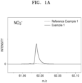
- the dry electrode film may include nitrogen-containing anions, and the nitrogen-containing anions may include, for example, NO 3 - , NO 2 - , NO - , or any suitable combination thereof. Because the dry electrode film includes NO 3 - , NO 2 - ; NO - , or any suitable combination thereof, a decrease in the interfacial resistance between the dry electrode film and the electrolyte may be more effectively achieved. Referring to FIGs. 1A to 1C , by mass spectrometry of the dry electrode film, the nitrogen-containing anions may show a peak corresponding to NO 3 - , a peak corresponding to NO 2 - , a peak corresponding to NO - , or a combination of the peaks thereof. The presence of nitrogen-containing anions may be confirmed through mass spectrometry of the dry electrode film.
- the dry electrode film may be measured for charge transfer resistance (R ct ), for example, by electrochemical impedance spectroscopy.
- R ct charge transfer resistance
- an In(1/R ct ) vs. 1/T graph may be plotted from temperature-dependent charge transfer resistance data, and from the slope (-E a /R) of this graph, charge transfer activation energy (E a ) may be derived.
- the charge transfer activation energy (E a ) may be 15 KJ/mol or less, 14 KJ/mol or less, 13 KJ/mol or less, 12 KJ/mol or less, or 11 KJ/mol or less.
- the charge transfer activation energy (E a ) may be about 1 KJ/mol to about 15 KJ/mol, about 2 KJ/mol to about 14 KJ/mol, about 3 KJ/mol to about 13 KJ/mol, about 4 KJ/mol to about 12 KJ/mol, or about 5 KJ/mol to about 11 KJ/mol. Because the dry electrode film has such a low charge transfer activation energy in the above ranges, the interfacial resistance between the dry electrode film and the electrolyte may decrease.
- R ct represents charge transfer resistance
- A represents pre-exponential factor
- E a charge transfer activation energy
- R represents the gas constant
- T represents absolute temperature
- the capacity per unit area of the dry electrode film may be, for example, more than 8.0 mA/cm 2 , 8.5 mAh/cm 2 or more, 9.0 mAh/cm 2 or more, 9.5 mAh/cm 2 or more, 10.0 mAh/cm 2 or more, or 11 mAh/cm 2 or more.
- the capacity per unit area of the dry electrode film may be, for example, more than 8.0 mAh/cm 2 to about 40 mAh/cm 2 , about 8.5 mAh/cm 2 to about 40 mAh/cm 2 , about 9.0 mAh/cm 2 to about 35 mAh/cm 2 , about 9.5 mAh/cm 2 to about 30 mAh/cm 2 , about 10.0 mAh/cm 2 to about 25 mAh/cm 2 , or about 11 mAh/cm 2 to about 20 mAh/cm 2 . Because the dry electrode film has such a high capacity per unit area in the above ranges, the energy density of a lithium battery including the dry electrode film may improve. As the thickness of the dry electrode film increases, the capacity per unit area of the dry electrode film may increase.
- the dry electrode film includes a nitrogen-containing anion, a nitrile group-containing compound, or any suitable combination thereof, despite increased capacity per unit area of the dry electrode film, a rapid increase in charge transfer resistance (R ct ) may be suppressed or reduced. Therefore, the difference between charge transfer resistance (R ct ) and ion resistance (R ion ) in the dry electrode film as measured at 25 °C by electrochemical impedance spectroscopy may be 10 ohm ⁇ cm 2 or less, 8 ohm ⁇ cm 2 or less, 6 ohm ⁇ cm 2 or less, or 4 ohm ⁇ cm 2 or less.
- the difference between charge transfer resistance (R ct ) and ion resistance (R ion ) in the dry electrode film is limited to the above ranges, despite increased capacity per unit area of the dry electrode film, deterioration in the cycling performance of a lithium battery including the dry electrode film may be suppressed or reduced.
- the charge transfer resistance (R ct ) may be more than the ion resistance (R ion ).
- the difference between charge transfer resistance (R ct ) and ion resistance (R ion ) in the dry electrode film as measured by electrochemical impedance spectroscopy may be, for example, about 1 ohm ⁇ cm 2 to about 10 ohm ⁇ cm 2 , about 1 ohm ⁇ cm 2 to about 8 ohm ⁇ cm 2 , about 1 ohm ⁇ cm 2 to about 6 ohm ⁇ cm 2 , or about 1 ohm ⁇ cm 2 to about 4 ohm ⁇ cm 2 .
- the dry electrode film may include, for example, a first lithium salt compound.
- the first lithium salt compound may be, for example, a salt compound including a lithium cation and a nitrogen-containing anion.
- the nitrogen-containing anion may be derived from the first lithium salt compound.
- the nitrogen-containing anion may be present as a first lithium salt in the dry electrode film.
- the amount of the first lithium salt compound may be, for example, about 0.1 wt% to about 3 wt%, about 0.1 wt% to about 2.5 wt%, about 0.1 wt% to about 2 wt%, about 0.1 wt% to about 1.5 wt%, or about 0.1 wt% to about 1 wt% (e.g. about 0.2 wt% to about 0.8 wt%, about 0.3 wt% to about 0.5 wt%, or about 0.3 wt% to about 0.4 wt%), with respect to the total weight of the dry electrode film.
- the dry electrode film includes the first lithium salt compound in the above ranges, the internal resistance of a lithium battery including the dry electrode film may decrease more effectively, and the cycling performance of the lithium battery may further improve. If ( e.g. , when) the amount of the first lithium salt compound is excessively small, the effect thereof may be negligible. If ( e.g. , when) the amount of the first lithium salt compound is excessively high, anions derived from the first lithium salt may cover the anode within the lithium battery, which results in an increased internal resistance of the lithium battery and deteriorates the cycling performance of the lithium battery.
- the first lithium salt compound may be, for example, LiNOs. Because the dry electrode film includes LiNOs, the internal resistance of a lithium battery including the dry electrode film may further decrease, and the cycling performance of the lithium battery may further improve.
- the dry electrode film may further include, for example, a second lithium salt compound.
- the second lithium salt compound may also be referred to as, for example, a lithium-containing compound. Because the dry electrode film additionally includes a second lithium salt compound, the cycling performance of a lithium battery including the dry electrode film may further improve. Because the dry electrode film additionally includes a second lithium salt compound, a decrease in the initial capacity of a lithium battery due to irreversible reactions occurring upon charging and discharging of the lithium battery may be effectively prevented or reduced. For example, the second lithium salt compound may be irreversibly oxidized or degraded during initial charging. For example, the second lithium salt compound may have a lower initial charge-discharge efficiency relative to the dry cathode active material.
- the initial charge-discharge efficiency of the second lithium salt compound may be 50 % or less, 40 % or less, 30 % or less, 20 % or less, or 10 % or less, with respect to the initial charge-discharge efficiency of the dry cathode active material.
- Lithium ions derived from the second lithium salt compound may be utilized in irreversible reactions e.g., formation of solid electrolyte layers on the anode surface during initial charging. Because the dry electrode film additionally includes the second lithium salt compound, lithium ions consumed in such irreversible reactions during initial charging may be mostly the lithium ions derived from the second lithium salt compound, while lithium ions derived from the dry electrode active materials remain unused.
- the dry electrode film may retain its design capacity, despite side reactions during initial charging and discharging of the lithium battery. Therefore, a lithium battery including the dry electrode film may be protected from a capacity decrease due to initial irreversible reactions in the lithium battery.
- the second lithium salt compound may include LiNO 2 , Li 2 O, Li 2 S, Li 3 N, LiF, Li 5 FeO 4 , Li 2 NiO 2 , Li 6 CO 4 , Li 2 MoO 3 , or any suitable combination thereof.
- the amount of the second lithium salt compound may be, for example, about 0.1 wt% to about 5 wt%, about 0.1 wt% to about 3 wt%, or about 0.1 wt% to about 2 wt%, with respect to the total weight of the dry electrode film.
- the second lithium salt compound in an amount within the above ranges, a decrease in the initial capacity of a lithium battery including the dry electrode film may be more effectively suppressed or reduced.
- the dry electrode film may include a nitrile group-containing compound, and because the dry electrode film including a nitrile group-containing compound, a lithium battery including the dry electrode film may have decreased internal resistance as well as improved high-temperature stability of the lithium battery. For example, with the dry electrode film including a nitrile group-containing compound, thickness changes of the lithium battery may be reduced during high-temperature charging and discharging of the lithium battery.
- the amount of the nitrile group-containing compound may be, for example, about 0.1 wt% to about 3 wt%, about 0.1 wt% to about 2.5 wt%, about 0.1 wt% to about 2 wt%, about 0.1 wt% to about 1.5 wt%, or about 0.1 wt% to about 1 wt% (e.g. about 0.2 wt% to about 0.8 wt%, about 0.5 wt% to about 0.7 wt%, or about 0.6 wt% to about 0.7 wt%), with respect to the total weight of the dry electrode film.
- the internal resistance of a lithium battery including the dry electrode film may decrease more effectively, and the cycling performance of the lithium battery may further improve. If ( e.g. , when) the amount of the nitrile group-containing compound is excessively small, the effect thereof may be negligible. If ( e.g. , when) the amount of the nitrile group-containing compound is excessively high, the nitrile group-containing compound covers the anode within the lithium battery, and as a result, the internal resistance of the lithium battery may increase, and the cycling performance of the lithium battery may deteriorate.
- the nitrile group-containing compound may be a compound containing, for example, two or more nitrile groups.
- the number of nitrile groups in the nitrile group-containing compound may be, for example, about 2 to about 9, about 2 to about 7, about 2 to about 5, about 2 to about 3, or may be about 2.
- a lithium battery including the dry electrode film may have further improved cycling performance and further improved high-temperature stability.
- the nitrile group-containing compound may be a nitrile group-containing organic compound.
- the nitrile group-containing compound may include, for example, succinonitrile, adiponitrile, pentane-1,2,3-tricyanide (i.e., 1,2,3-pentantricarbonitrile), pentane-1,2,5-tricyanide (i.e., 1,2,5-pentantricarbonitrile), hexane-1,2,6-tricyanide (i.e., 1,2,6-hexanetricarbonitrile), hexane-1,3,6-tricyanide (i.e., 1,3,6-hexanetricarbonitrile), or any suitable combination thereof.
- the nitrile group-containing compound may be succinonitrile.
- the dry electrode film may have a core-shell structure, and the shell may continuously or discontinuously conform to a surface of the core.
- the shell including the first metal oxide disposed in the matrix of the first carbonaceous material
- the shell may be more uniformly (substantially more uniformly) disposed on the core.
- the shell uniformly (substantially uniformly) disposed on the core effectively prevents the core and electrolyte from coming into contact with each other, side reactions due to a contact between the core and the electrolyte may be prevented or reduced.
- the first carbonaceous material may be, for example, a crystalline carbonaceous material.
- the first carbonaceous material may be, for example, a carbonaceous nanostructure.
- the first carbonaceous material may be, for example, a carbonaceous two-dimensional nanostructure.
- the first carbonaceous material may be graphene.
- the shell including graphene and/or a matrix thereof has flexibility
- volume changes of the dry electrode active material may be easily accommodated during charging and discharging, such that crack formation inside the dry electrode active material may be inhibited or reduced.
- Due to high electronic conductivity of graphene the interfacial resistance between the dry electrode active material and the electrolyte may decrease.
- an increase in the internal resistance of a lithium battery may be inhibited or reduced.
- a carbonaceous material in the related art not containing first metal oxides easily agglomerates, substantially uniform disposition on the cores of the dry electrode active material may be difficult.
- the matrix of the first carbonaceous material is derived from, for example, a graphene matrix, the first carbonaceous material has lower density and higher porosity relative to the carbonaceous material derived from graphitic material in the related art.
- the shell may further include at least one second metal oxide.
- the second metal oxide may be represented by M a O c (0 ⁇ a ⁇ 3 and 0 ⁇ c ⁇ 4, wherein if ( e.g. , when) a is 1, 2, or 3, c is an integer) wherein M is at least one metal of ( e.g. , at least one metal selected from among) Groups 2 to 16 of the Periodic Table of the Elements, for example, Groups 2 to 13, Group 15, and/or Group 16 of the Periodic Table of Elements (e.g., at least one metal selected from Group 13 of the Periodic Table of Elements).
- the second metal oxide may include the same metal as the first metal oxide.
- the second metal oxide may be (e.g., may be selected from among) Al 2 O 3 , NbO, NbO 2 , Nb 2 O 3 , MgO, Sc 2 O 3 , TiO 2 , ZrO 2 , V 2 O 3 , WO 2 , MnO 2 , Fe 2 O 3 , Co 3 O 4 , PdO, CuO, AgO, ZnO, Sb 2 O 3 , and/or SeO 2 .
- the first metal oxide may be, for example, a reduction product of the second metal oxide.
- the first metal oxide may be obtained from a partial or complete reduction of the second metal oxide. Therefore, the first metal oxide may have a lower oxygen content ( e.g. , amount) and a lower oxidation number of the metal, relative to the second metal oxide.
- the shell may include Al 2 O x (0 ⁇ x ⁇ 3) as the first metal oxide, and Al 2 O 3 as the second metal oxide
- the shell may include, for example, at least one of ( e.g. , at least one selected from among) the first metal oxide and/or the second metal oxide.
- the at least one of ( e.g. , at least one selected from among) the first metal oxide and/or the second metal oxide may have a particle diameter (e.g. average particle diameter, such as D50) of, for example, about 0.1 nm to about 100 nm, about 0.5 nm to about 100 nm, about 1 nm to about 100 nm, about 1 nm to about 50 nm, about 1 nm to about 30 nm, about 5 nm to about 30 nm, or about 10 nm to about 30 nm.
- the first metal oxide and/or the second metal oxide having a particle diameter in the above nano-size ranges, the first metal oxide and/or the second metal oxide may be more uniformly (substantially more uniformly) distributed within the matrix of the first carbonaceous material. If ( e.g. , when) the particle diameter of at least one of the first metal oxide and/or the second metal oxide excessively increases, the thickness of the shell increases, which may result in an increase in the internal resistance of a composite anode active material. If ( e.g. , when) the particle diameter of at least one of the first metal oxide and/or the second metal oxide excessively decreases, substantially uniform dispersion may be difficult.
- the shell may include the first metal oxide and/or the second metal oxide and may include the first carbonaceous material.
- the first carbonaceous material may be disposed in a direction protruding from the surface of the first metal oxide and/or the second metal oxide.
- the first carbonaceous material may be disposed in a direction protruding from the surface of the first metal oxide and/or the second metal oxide by directly growing from the surface of the first metal oxide and/or the second metal oxide.
- the first carbonaceous material disposed in a direction protruding from the surface of the first metal oxide and/or the second metal oxide may be, for example, a two-dimensional carbonaceous nanostructure, a carbonaceous flake, or graphene.
- the shell may have a thickness of, for example, about 0.1 nm to about 5 ⁇ m, about 0.5 nm to about 5 ⁇ m, about 1 nm to about 5 ⁇ m, about 1 nm to about 1 ⁇ m, about 1 nm to about 500 nm, about 1 nm to about 200 nm, about 1 nm to about 100 nm, about 1 nm to about 50 nm, about 1 nm to about 30 nm, or about 1 nm to about 20 nm.
- a dry electrode including the dry electrode active material may have further improved electronic conductivity and further decreased internal resistance.
- the shell may have a monolayer structure or a multilayer structure.
- the multilayer structure may have, for example, a two-layer structure, a three-layer structure, or a four-layer structure.
- the type or kind of metal in the first metal oxide that each layer contains may be different from each other.
- the amount of the shell may be about 0.01 wt% to about 5 wt%, about 0.01 wt% to about 3 wt%, about 0.01 wt% to about 2 wt%, or about 0.01 wt% to about 1 wt% (e.g. about 0.1 wt% to about 0.5 wt%. or about 0.2 wt% to about 0.4 wt%), with respect to the total weight of dry electrode active material.
- the amount of the first metal oxide may be, for example, about 0.006 wt% to about 3 wt%, about 0.006 wt% to about 1.8 wt%, about 0.006 wt% to about 1.2 wt%, or about 0.006 wt% to about 0.6 wt% (e.g. about 0.06 wt% to about 0.3 wt%, or about 0.12 wt% to about 0.24 wt%), with respect to the total weight of dry electrode active material.
- the dry electrode active material includes the shell and the first metal oxide in an amount in the above ranges, respectively, the cycling performance of a lithium battery may further improve.
- the dry electrode active material may further include a third metal doped on a core, or a third metal oxide coated on the core.
- the shell may be disposed on the third metal doped on the core or on the third metal oxide coated on the core.
- the shell may be disposed on the third metal and/or the third metal oxide, after the third metal is doped on the surface of a compound, e.g ., a lithium transition metal oxide included in the core, or after the third metal oxide is coated on the surface of a compound, e.g. , a lithium transition metal oxide included in the core.
- the dry electrode active material may include, for example: a core; an interlayer disposed on the core; and a shell disposed on the interlayer, wherein the interlayer may include a third metal or a third metal oxide.
- the third metal may be at least one metal of ( e.g. , at least one metal selected from among) Al, Zr, W, and/or Co, and the third metal oxide may be Al 2 O 3 , Li 2 O-ZrO 2 , WO 2 , CoO, Co 2 O 3 , Co 3 O 4 , or any suitable combination thereof.
- the shell conforming to the surface of the core may be, for example, a dry-coating layer.
- the shell may be introduced onto the core by a dry method, for example, by milling.
- the shell conforming to the surface of the core may include, for example, a composite that contains a first metal oxide and a first carbonaceous material, e.g. , graphene, and at least one of ( e.g. , at least one selected from among) milling products of the composite.
- the first metal oxide may be disposed in a matrix of a first carbonaceous material, for example, a graphene matrix.
- the shell may be prepared from a composite that includes a first metal oxide and a first carbonaceous material, e.g. , graphene.
- the composite may further include a second metal oxide in addition to the first metal oxide.
- the composite may include two or more types (kinds) of first metal oxides.
- the composite may include two or more types (kinds) of first metal oxides, and two or more types (kinds) of second metal oxides.
- the amount of the composite and at least one of the milling products thereof may be, for example, 5 wt% or less, 3 wt% or less, 2 wt% or less, 1 wt% or less, or 0.5 wt% or less, relative to the total weight of the dry electrode active material.
- the amount of at least one of the composite and a milling product thereof may be about 0.01 wt% to about 5 wt%, about 0.01 wt% to about 3 wt%, about 0.01 wt% to about 1 wt%, about 0.01 wt% to about 0.7 wt%, or about 0.01 wt% to about 0.5 wt%, with respect to the total weight of the dry electrode active material.
- the dry electrode active material includes the composite and at least one of milling products thereof in an amount in the above ranges, the cycling performance of a lithium battery including the dry electrode active material may further improve.
- the composite may further include at least one of ( e.g. , at least one selected from among) a first metal oxide and/or a second metal oxide.
- the at least one of ( e.g., at least one selected from among) a first metal oxide and/or a second metal oxide may have a particle diameter (e.g. average particle diameter, such as D50) of about 0.1 nm to about 100 nm, about 0.5 nm to about 100 nm, about 1 nm to about 100 nm, about 1 nm to about 50 nm, about 1 nm to about 30 nm, about 5 nm to about 30 nm, or about 10 nm to about 30 nm.
- the first metal oxide and/or the second metal oxide may be more uniformly (substantially more uniformly) distributed in the matrix of the first carbonaceous material of the composite. Therefore, the composite may be uniformly coated (substantially uniformly coated) on the core without agglomeration and form a shell. Further, as the first metal oxide and/or the second metal oxide have a particle diameter in the above ranges, the first metal oxide and/or the second metal oxide may be more uniformly (substantially more uniformly) disposed on the core.
- the particle diameter of the first metal oxide and/or the second metal oxide may be measured, for example, by utilizing a measurement device utilizing a laser diffraction technique or a dynamic light scattering technique.
- the particle diameter may be measured by, for example, a laser scattering particle size distribution analyzer (e.g. , LA-920 manufactured by HORIBA) and is a volume-based median particle diameter (D50) at a cumulative percentage of 50 % from the smallest particle size.
- the uniformity (substantial uniformity) of at least one selected from among the first metal oxide and/or the second metal oxide may have a deviation of 3 % or less, 2 % or less, or 1 % or less.
- the uniformity (substantial uniformity) may be measured, for example, by XPS. Therefore, the at least one of ( e.g., at least one selected from among) the first metal oxide and/or the second metal oxide may be uniformly (substantially uniformly) distributed within the composite with a deviation of 3 % or less, 2 % or less, or 1 % or less.
- the composite may include a first carbonaceous material.
- the first carbonaceous material may have a branched structure, and at least one metal oxide of (e.g. , at least one metal oxide selected from among) the first metal oxide and/or the second metal oxide may be distributed in the branched structure of the first carbonaceous material.
- the branched structure of the first carbonaceous material may include, for example, a plurality of first carbonaceous material particles in contact with one another.
- the first carbonaceous material has such a branched structure, one or more suitable conduction paths may be provided.
- the first carbonaceous material may be a graphene.
- the graphene may have a branched structure, and at least one metal oxide of (e.g.
- At least one metal oxide selected from among) the first metal oxide and/or the second metal oxide may be distributed within the branched structure of the graphene.
- the branched structure of the graphene may include, for example, a plurality of graphene particles in contact with one another. As the graphene has such a branched structure, one or more suitable conduction paths may be provided.
- the first carbonaceous material may have, for example, a spherical structure, and at least one metal oxide of (e.g. , at least one metal oxide selected from among) the first metal oxide and/or the second metal oxide may be distributed in the spherical structure.
- the spherical structure of the first carbonaceous material may have a size of about 50 nm to about 300 nm.
- a plurality of particles of the first carbonaceous material (e.g., in a form of particles) having (each having) a spherical structure may be provided.
- the composite may have a secure structure.
- the first carbonaceous material may be a graphene.
- the graphene may have a spherical structure, and at least one metal oxide of (e.g. , at least one metal oxide selected from among) the first metal oxide and/or the second metal oxide may be distributed within the spherical structure.
- the spherical structure of the graphene may have a size of about 50 nm to about 300 nm.
- a plurality of graphene particles having (each having) a spherical structure may be provided.
- the composite may have a secure structure.
- the first carbonaceous material may have, for example, a spiral structure in which a plurality of spherical structures are connected, and at least one metal oxide of (e.g. , at least one metal oxide selected from among) the first metal oxide and/or the second metal oxide may be distributed within the spherical structures of the spiral structure.
- the spiral structure of the first carbonaceous material may have a size of about 500 nm to about 100 ⁇ m.
- the composite may have a secure structure.
- the first carbonaceous material may be graphene.
- the graphene may have, for example, a spiral structure in which a plurality of spherical structures are connected, and at least one metal oxide of (e.g.
- At least one metal oxide selected from among) the first metal oxide and/or the second metal oxide may be distributed within the spherical structures of the spiral structure.
- the spiral structure of the graphene may have a size of about 500 nm to about 100 ⁇ m. As the graphene has a spiral structure, the composite may have a secure structure.
- the first carbonaceous material may have, for example, a cluster structure (e.g., a secondary particle) in which a plurality of spherical structures (e.g., a plurality of primary particles) are agglomerated, and at least one metal oxide of (e.g. , at least one metal oxide selected from among) the first metal oxide and/or the second metal oxide may be distributed within the spherical structures of the cluster structure.
- the cluster structure of the first carbonaceous material may have a size of about 0.5 mm to about 10 cm.
- the composite may have a secure structure.
- the first carbonaceous material may be graphene.
- the graphene may have, for example, a cluster structure in which a plurality of spherical structures are agglomerated, and at least one metal oxide of (e.g. , at least one metal oxide selected from among) the first metal oxide and/or the second metal oxide may be distributed within the spherical structures of the cluster structure.
- the cluster structure of the graphene may have a size of about 0.5 mm to about 10 cm.
- the composite may have a secure structure.
- the composite may have, for example, a crumpled faceted-ball structure, and at least one of (e.g. , at least one metal oxide selected from among) the first metal oxide and/or the second metal oxide may be distributed inside the structure or on the surface of the structure.
- the composite may be easily coated on surface irregularities of the core.
- the composite may be or have a planar structure, and at least one of (e.g. , at least one metal oxide selected from among) the first metal oxide and/or the second metal oxide may be distributed inside or on the surface of the structure.
- the composite may be easily applied on surface irregularities of the core.
- the first carbonaceous material may extend from the first metal oxide by a distance of 10 nm or less, and may include at least 1 to 20 carbonaceous material layers.
- the first carbonaceous material having a total thickness of 12 nm or less may be disposed on the first metal oxide.
- the total thickness of the first carbonaceous material may be about 0.6 nm to about 12 nm.
- the first carbonaceous material may be a graphene.
- the graphene may extend from the first metal oxide by a distance of 10 nm or less, and may include at least 1 to about 20 graphene layers.
- graphene having a total thickness of 12 nm or less may be disposed on the first metal oxide.
- the total thickness of the graphene may be about 0.6 nm to about 12 nm.
- the shell may further include a second carbonaceous material distinguished from the first carbonaceous material.
- the shell may include, for example, a fibrous carbon having an aspect ratio of 10 or more, as a second carbonaceous material.
- the conduction path in the dry electrode active material may be further elongated.
- the second carbonaceous material may reduce the internal resistance of a dry electrode that includes the dry electrode active material.
- a substantially uniform and stable three-dimensional conductive network may be formed between the plurality of dry electrode active materials.
- a lithium battery provided with the dry electrode active material may have improved high-rate capability. It can be difficult to form a substantially uniform three-dimensional conductive network among a plurality of core particles by utilizing a simple mixture of the core and the second carbonaceous material, which is fibrous carbon, due to agglomeration of fibrous carbon and/or the like.
- a second carbonaceous material 23 may be disposed on a surface of the dry electrode active material 100, as shown, for example, in FIG. 3 .
- the dry electrode active material 100 may include a core 10, and a shell 20 continuously or discontinuously conforming to a surface of the core 10.
- the shell 20 may completely or partially cover the core 10.
- the shell 20 may include a first metal oxide 21, a first carbonaceous material 22, and a second carbonaceous material 23.
- the second carbonaceous material 23 may protrude from a surface of the dry electrode active material 100.
- the second carbonaceous material 23 may effectively provide a conductive network among a plurality of dry electrode active material particles. As the second carbonaceous material 23 is disposed in the matrix of the first carbonaceous material 22, the second carbonaceous material 23 may be easily coated on the core 10.
- the matrix of the first carbonaceous material 22 may act as a binder that binds the core and the second carbonaceous material 23 together. Therefore, the absence of the matrix of the first carbonaceous material 22 may make coating of the second carbonaceous material 23 on the core 10 difficult, or may cause the second carbonaceous material 23 to easily delaminate from the core 10 during the cathode slurry preparation process. If ( e.g., when) a binder is added to bind a lithium transition metal oxide core 10 and the second carbonaceous material 23, as the core 10 is covered with an insulating binder, the internal resistance of the dry electrode active material 100 may increase. If ( e.g. , when) the core covered with the binder and the second carbonaceous material are subjected to a high-temperature heat treatment to carbonize the binder, the core 10 and the second carbonaceous material 23 may degrade during the heat treatment.
- the second carbonaceous material may have an aspect ratio of 10 or more, or 20 or more.
- the second carbonaceous material may have an aspect ratio of about 10 to about 100,000, about 10 to about 80,000, about 10 to about 50,000, about 10 to about 10,000, about 10 to about 5,000, about 10 to about 1,000, about 10 to about 500, about 10 to about 100, or about 10 to about 50.
- the aspect ratio of the second carbonaceous material is, for example, a ratio of length (e.g. average length) of the major axis passing through the center of the second carbonaceous material to length (e.g.
- the aspect ratio and the lengths (e.g. average lengths) of the major and minor axes may be determined from SEM images.
- the second carbonaceous material may have a diameter (e.g. average diameter) of 50 nm or less, 30 nm or less, 20 nm or less, or 10 nm or less.
- the second carbonaceous material may have a diameter (e.g. average diameter) of about 1 nm to about 50 nm, about 1 nm to about 30 nm, or about 1 nm to about 10 nm.
- the diameter (e.g. average diameter) of the second carbonaceous material may be determined from SEM images. If ( e.g. , when) the diameter of the second carbonaceous material is excessively large, the absolute number of filaments per unit volume decreases and thus, the effect of reducing the internal resistance may become insignificant. If ( e.g., when) the diameter of the second carbonaceous material is excessively small, substantially uniform dispersion may be difficult.
- the second carbonaceous material may have a length (e.g. average length) of 1,000 ⁇ m or less, 100 ⁇ m or less, 50 ⁇ m or less, 10 ⁇ m or less, 5 ⁇ m or less, 2 ⁇ m or less, 1 ⁇ m or less, 500 nm or less, or 300 nm or less.
- the second carbonaceous material may have a length (e.g.
- the second carbonaceous material may have a length (e.g.
- the length (e.g. average length) of the second carbonaceous material may be determined from SEM images. As the length of the second carbonaceous material increases, the internal resistance of the electrode may decrease. If ( e.g. , when) the length of the second carbonaceous material is excessively small, it may be difficult to provide an effective conduction path.
- the second carbonaceous material may include, for example, a carbon nanofiber, a carbon nanotube, or any suitable combination thereof.
- the carbon nanotubes may include a primary carbon nanotube structure, a secondary carbon nanotube structure formed by agglomeration of a plurality of primary carbon nanotube particles, or any suitable combination thereof.
- the primary carbon nanotube structure may be one carbon nanotube unit.
- the carbon nanotube unit has a graphite sheet having a cylindrical form with a nano-sized diameter and a sp 2 bond structure. Depending on the bending angle and structure of the graphite sheet, the characteristics of conductors, or the characteristics of semiconductors may be exhibited.
- the carbon nanotube unit may be classified, depending on the number of bonds constituting a wall, into a single-walled carbon nanotube (SWCNT), a double-walled carbon nanotube (DWCNT), a multi-walled carbon nanotube (MWCNT), and/or the like. The smaller the wall thickness of the carbon nanotube unit, the lower the resistance.
- the primary carbon nanotube structure may include, for example, an SWCNT, a DWCNT, an MWCNT, or any suitable combination thereof.
- the primary carbon nanotube structure may have a diameter (e.g. average diameter) of 1 nm or more, or 2 nm or more.
- the primary carbon nanotube structure may have a diameter (e.g. average diameter) of 20 nm or less, or 10 nm or less.
- the primary carbon nanotube structure may have a diameter (e.g. average diameter) of about 1 nm to about 20 nm, about 1 nm to about 15 nm, or about 1 nm to about 10 nm.
- the primary carbon nanotube structure may have a length (e.g.
- the primary carbon nanotube structure may have a length (e.g. average length) of 2 ⁇ m or less, 1 ⁇ m or less, 500 nm or less, or 300 nm or less.
- the primary carbon nanotube structure may have a length (e.g. average length) of about 100 nm to about 2 ⁇ m, about 100 nm to about 1 ⁇ m, about 100 nm to about 500 nm, about 100 nm to about 400 nm, about 100 nm to about 300 nm, or about 200 nm to about 300 nm.
- the diameter and length of the primary carbon nanotube structure may be measured from a scanning electron microscope (SEM) image or a transmission electron microscope (TEM) image. In one or more embodiments, the diameter and/or length of the primary carbon nanotube structure may be measured by a laser diffraction method.
- SEM scanning electron microscope
- TEM transmission electron microscope
- the secondary carbon nanotube structure may be a structure formed by assembling the primary carbon nanotube structure to form a bundle type or kind or a rope type or kind, in whole or in part.
- the secondary carbon nanotube structure may include, for example, bundle-type or kind carbon nanotubes, rope-type or kind carbon nanotubes, or any suitable combination thereof.
- the secondary carbon nanotube structure may have a diameter (e.g. average diameter) of 2 nm or more, or 3 nm or more.
- the secondary carbon nanotube structure may have a diameter of 50 nm or less, 30 nm or less, 20 nm or less, or 10 nm or less.
- the secondary carbon nanotube structure may have a diameter (e.g.
- the secondary carbon nanotube structure may have a length (e.g. average length) of 500 nm or more, 700 nm or more, 1 ⁇ m or more, or 10 ⁇ m or more.
- the secondary carbon nanotube structure may have a length (e.g. average length) of 1,000 ⁇ m or less, 500 ⁇ m or less, or 100 ⁇ m or less.
- the secondary carbon nanotube structure may have a length (e.g.
- the diameter and length of the secondary carbon nanotube structure may be measured from an SEM image or an optical microscope image.
- the diameter and/or length of the secondary carbon nanotube structure may be measured by a laser diffraction method.
- the secondary carbon nanotube structure may be utilized in the preparation of the dry electrode active material, for example, by being dispersed in a solvent and/or the like, and converted into the primary carbon nanotube structure.
- the amount of the second carbonaceous material may be, for example, about 0.1 wt% to about 50 wt%, about 1 wt% to about 40 wt%, or about 5 wt% to about 30 wt%, with respect to the total weight of the first carbonaceous material and the second carbonaceous material.
- Including the first carbonaceous material and the second carbonaceous material within the above ranges in the dry electrode active material may more effectively secure conduction paths in the dry electrode active material and therefore, may further decrease the internal resistance of the dry electrode active material. As a result, the cycling performance of a lithium battery including the dry electrode active material may further improve.
- the amount of the second carbonaceous material may be, for example, about 0.001 wt% to about 5 wt%, about 0.01 wt% to about 3 wt%, about 0.01 wt% to about 1 wt%, about 0.01 wt% to about 0.5 wt%, or about 0.01 wt% to about 0.1 wt%, with respect to the total weight of the dry electrode active material. Because the dry electrode active material includes the second carbonaceous material within the above ranges, conduction paths in the dry electrode active material may be secured, further decreasing the internal resistance of the dry electrode active material. As a result, the cycling performance of a lithium battery including the dry electrode active material may further improve.
- the dry electrode active material may have a core, and the core may include, for example, a lithium transition metal oxide.
- the core may include a compound of ( e.g. , selected from among) lithium transition metal oxides represented by Formulas 1 to 8: Formula 1 Li a Ni x Co y M z O 2-b A b
- M may be manganese (Mn), niobium (Nb), vanadium (V), magnesium (Mg), gallium (Ga), silicon (Si), tungsten (W), molybdenum (Mo), iron (Fe), chromium (Cr), copper (Cu), zinc (Zn), titanium (Ti), aluminium (Al), boron (B), or any suitable combination thereof, and A may be F, S, Cl, Br, or any suitable combination thereof.
- M may be manganese (Mn), niobium (Nb), vanadium (V), magnesium (Mg), gallium (Ga), silicon (Si), tungsten (W), molybdenum (Mo), iron (Fe), chromium (Cr), copper (Cu), zinc (Zn), titanium (Ti), aluminium (Al), boron (B), or any suitable combination thereof, and A may be F, S, Cl, Br, or any suitable combination thereof.
- Formula 2 LiNi x Co y Mn
- M may be manganese (Mn), niobium (Nb), vanadium (V), magnesium (Mg), gallium (Ga), silicon (Si), tungsten (W), molybdenum (Mo), iron (Fe), chromium (Cr), copper (Cu), zinc (Zn), titanium (Ti), aluminium (Al), boron (B), or any suitable combination thereof, and A may be F, S, Cl, Br, or any suitable combination thereof.
- M may be manganese (Mn), niobium (Nb), vanadium (V), magnesium (Mg), gallium (Ga), silicon (Si), tungsten (W), molybdenum (Mo), iron (Fe), chromium (Cr), copper (Cu), zinc (Zn), titanium (Ti), aluminium (Al), boron (B), or any suitable combination thereof, and A may be F, S, Cl, Br, or any suitable combination thereof.
- Formula 6 Li a Ni x Mn y
- M' may be cobalt (Co), niobium (Nb), vanadium (V), magnesium (Mg), gallium (Ga), silicon (Si), tungsten (W), molybdenum (Mo), iron (Fe), chromium (Cr), copper (Cu), zinc (Zn), titanium (Ti), aluminium (Al), boron (B), or any suitable combination thereof, and A may be F, S, Cl, Br, or any suitable combination thereof.
- Formula 7 Li a M1 x M2 y PO 4-b X b
- M1 may be chromium (Cr), manganese (Mn), iron (Fe), cobalt (Co), nickel (Ni), copper (Cu), zirconium (Zr), or any suitable combination thereof
- M2 may be magnesium (Mg), calcium (Ca), strontium (Sr), barium (Ba), titanium (Ti), zinc (Zn), boron (B), niobium (Nb), gallium (Ga), indium (In), molybdenum (Mo), tungsten (W), aluminium (Al), silicon (Si), chromium (Cr), vanadium (V), scandium (Sc), yttrium (Y), or any suitable combination thereof
- X may be O, F, S, P, or any suitable combination thereof.
- Formula 8 Li a M3 z PO 4
- M3 may be chromium (Cr), manganese (Mn), iron (Fe), cobalt (Co), nickel (Ni), copper (Cu), zirconium (Zr), or any suitable combination thereof.
- the shell may include the first metal oxide and the first carbonaceous material
- the core may include, for example, a lithium transition metal oxide.
- the first carbonaceous material and the transition metal of the lithium transition metal oxide may be, for example, chemically bound by a chemical bond.
- the carbon atom (C) of the first carbonaceous material and the transition metal (Me) of the lithium transition metal oxide may be chemically bound, for example, through a C-O-Me bond via oxygen atoms ( e.g. , C-O-Ni bond, or C-O-Co bond).
- the chemical binding of the first carbonaceous material disposed in the shell and the lithium transition metal oxide disposed in the core by a chemical bond may lead to complexation of the core and the shell.
- the resulting dry electrode active material may be distinguished from a simple physical mixture or blend of the first carbonaceous material and the lithium transition metal oxide.
- the first metal oxide and the first carbonaceous material may be chemically bound by a chemical bond.
- the chemical bond may be, for example, a covalent bond or an ionic bond.
- the dry electrode active material may include, for example, a first dry electrode active material and a second dry electrode active material.
- the first dry electrode active material and the second dry electrode active material may have, for example, a different particle diameter (e.g. average particle diameter, such as D50) from each other.
- the first dry electrode active material may be a large-diameter dry electrode active material having a larger particle diameter (e.g. average particle diameter, such as D50) than that of the second dry electrode active material.
- the second dry electrode active material may be a small-diameter dry electrode active material having a smaller particle diameter (e.g. average particle diameter, such as D50) than that of the first dry electrode active material.
- the first dry electrode active material may be a large-particle dry electrode active material
- the second dry electrode active material may be a small-particle dry electrode active material.
- the second dry electrode active material having a smaller average particle diameter than that of the first dry electrode active material may be disposed in voids in the first dry electrode active material.
- the ionic conductivity and electronic conductivity of a dry electrode including the dry electrode active material may concurrently (e.g., simultaneously) improve. Further, the energy density of the dry electrode including the dry electrode active material may further improve. As a result, the energy density and cycling performance of a lithium battery including the dry electrode active material may improve.
- the first dry electrode active material and the second dry electrode active material may have, for example, a bimodal particle size distribution in a particle size distribution diagram.
- the composite cathode active material may show a bimodal particle size distribution having two peaks.
- the bimodal particle size distribution may have a first peak corresponding to the first dry electrode active material, and a second peak corresponding to the second dry electrode active material.
- a particle size ratio (e.g. average particle size ratio) of the first dry electrode active material and the second dry electrode active material may be, for example, about 3:1 to about 40:1, about 3:1 to about 30:1, about 3:1 to about 20:1, about 3:1 to about 10:1, or about 3:1 to about 5:1. Because the first dry electrode active material and the second dry electrode active material have a particle size ratio in the above ranges, the energy density and cycling performance of a lithium battery including the composite cathode active material may further improve.
- the first dry electrode active material (e.g., in a form of particles) may have a particle diameter (e.g. average particle diameter, such as D50) of about 8 ⁇ m to about 30 ⁇ m, about 9 ⁇ m to about 25 ⁇ m, about 9 ⁇ m to about 20 ⁇ m, about 9 ⁇ m to about 15 ⁇ m, or about 9 ⁇ m to about 12 ⁇ m.
- the particle diameter of the first dry electrode active material may be, for example, a median particle diameter (D50).
- the second dry electrode active material (e.g., in a form of particles) may have a particle diameter (e.g.
- the particle diameter of the second dry electrode active material may be, for example, a median particle diameter (D50). Because the first dry electrode active material and the second dry electrode active material have an average particle diameter in the above ranges, the energy density and/or cycling performance of a lithium battery including the composite cathode active material may further improve.
- the particle diameter e.g.
- average particle diameter, such as D50) of the first dry electrode active material and the second dry electrode active material are measured, for example, by utilizing a measurement device that uses a laser diffraction technique or a dynamic light scattering technique.
- the particle diameter e.g. average particle diameter, such as D50
- the particle diameter may be measured by, for example, a laser scattering particle size distribution analyzer (e.g. , LA-920 manufactured by HORIBA) and is a volume-based median particle diameter (D50) at a cumulative percentage of 50 % from the smallest particle size.
- the particle diameter (e.g. average particle diameter, such as D50) of the first dry electrode active material and the second dry electrode active material may be measured utilizing scanning electron microscope (SEM) images, or an optical microscope.
- a weight ratio of the first dry electrode active material and the second dry electrode active material may be, for example, about 90:10 to about 60:40, about 85:15 to about 65:35, about 80:20 to about 65:35, or about 75:25 to about 65:35. Because the weight ratio of the first dry electrode active material and the second dry electrode active material is in the above ranges, the energy density and/or cycling performance of a lithium battery including the composite cathode active material may further improve.
- the dry electrode film may include a dry binder.
- the dry binder is, for example, a binder that does not get impregnated, dissolved, or dispersed in processing solvents during the manufacturing process of a dry electrode film.
- the dry binder is, for example, a binder that does not contain processing solvents or does not come in contact with processing solvents during the manufacturing process of a dry electrode film.
- the dry binder is, for example, a fibrillized binder or a fibrous binder.
- the fibrillized binder or the fibrous binder may act as a matrix that supports and binds together electrode active materials and other components included in an electrode active material layer.
- the fibrous form of the fibrillized binder or the fibrous binder may be confirmed from, for example, a scanning electron microscopic image of a cross-section of an electrode.
- the fibrillized binder or the fibrous binder may have an aspect ratio of, for example, 10 or more, 20 or more, 50 or more, or 100 or more.
- the dry binder may include polytetrafluoroethylene (PTFE), a polyvinylidene fluoride-hexapropylene (PVDF-HFP) copolymer, polyvinylidene fluoride (PVDF), polyvinyl alcohol, polyacrylonitrile, carboxymethyl cellulose (CMC), starch, hydroxypropyl cellulose, cellulose, polyvinylpyrrolidone, polyethylene, polypropylene, an ethylene-propylene-diene polymer (EPDM), sulfonated-EPDM, styrene butadiene rubber (SBR), fluororubber, or a copolymer thereof; however, the dry binder is not limited thereto and may be any suitable binder usable in the preparation of a dry electrode.
- PTFE polytetrafluoroethylene
- PVDF-HFP polyvinylidene fluoride-hexapropylene
- PVDF polyvinylidene fluoride
- CMC
- the dry binder may include a fluorinated binder.
- the fluorinated binder may be, for example, polytetrafluoroethylene (PTFE), a polyvinylidene fluoride-hexapropylene (PVDF-HFP) copolymer, or polyvinylidene fluoride (PVDF).
- the dry binder may have a glass transition temperature T g of, for example, about -30 °C to about 150 °C, about 15 °C to about 150 °C, about 15 °C to about 130 °C, about 50 °C to about 130 °C, about 100 °C to about 130 °C, or about 120 °C to about 130 °C.
- the glass transition temperature T g of the dry binder may be, for example, about -30 °C to about 150 °C, about -30 °C to about 100 °C, about -30 °C to about 50 °C, about -30 °C to about 15 °C, about -30 °C to about -10 °C, or about -30 °C to about -20 °C.
- the glass transition temperature of PTFE is, for example, about 120 °C to about 130 °C.
- the glass transition temperature of the dry binder may be for example measured by DSC (Differential Scanning Calorimeter), DMA (Dynamic Mechanical Analyzer), TMA (Thermomechanical Analyzer), and/or TGA (Thermogravimetric Analyzer).
- the amount of the dry binder may be, for example, about 0.1 wt% to about 5 wt%, about 0.5 wt% to about 5 wt%, or about 1 wt% to about 5 wt% with respect to the total weight of the dry electrode film. Because the dry electrode film includes a dry binder in the above ranges, the dry electrode film may have improved adhesion and maintain high energy density.
- the dry electrode film may further include, for example, a conductive material.
- the conductive material may be a dry conductive material.
- the dry conductive material is, for example, a conductive material that does not get impregnated, dissolved, or dispersed in processing solvents during the manufacturing process of a dry electrode film.
- the dry conductive material is, for example, a conductive material that does not contain processing solvents or does not come in contact with processing solvents during the manufacturing process of a dry electrode film.
- the dry conductive material may include a carbonaceous conductive material.
- the carbonaceous conductive material may include, for example, a fibrous carbonaceous material having an aspect ratio of 10 or more, a particulate carbonaceous material having an aspect ratio of less than 10, or any suitable combination thereof.
- the fibrous carbonaceous material having an aspect ratio of 10 or more may be carbon fibers, carbon nanotubes, carbon nanobelts, and/or the like, but the present disclosure is not limited thereto, and may utilize any suitable material available as a carbonaceous conductive material in the art.
- the fibrous carbonaceous material having an aspect ratio of 10 or more may be ( e.g. , may be selected from among) the second carbonaceous materials described above.
- the fibrous carbonaceous conductive material is simply mixed with the dry electrode active material and in this regard, may be distinguished from the second carbonaceous material constituting part of the dry electrode active material.
- the particulate carbonaceous material having an aspect ratio of less than 10 may be, for example, carbon black, acetylene black, Ketjen black, natural graphite, artificial graphite, and/or the like, but the present disclosure is not limited thereto, and may utilize any suitable material available as a carbonaceous conductive material in the art.
- the aspect ratio of the particulate carbonaceous material may be, for example, about 1 to about 7, about 1 to about 5, about 1 to about 3, or about 1 to about 2.
- the amount of the dry conductive material included in the dry electrode film may be, for example, about 0.1 wt% to about 5 wt%, about 0.5 wt% to about 5 wt%, or about 1 wt% to about 5 wt%, with respect to the total weight of the dry electrode film.
- the dry electrode film may have improved conductivity by including the dry conductive material in the above ranges, and a lithium battery including this dry electrode film may have improved cycling performance.
- the dry electrode film may be a self-standing film.
- the dry electrode film may retain a film form without a support. Therefore, the dry electrode film may be prepared as a separate self-standing film and disposed on an electrode current collector.
- the dry electrode film may not contain any processing solvent deliberately added.
- the dry electrode film may contain no residual processing solvent. There may be a trace amount of solvent incidentally remaining in the dry electrode film; however, this solvent is not considered as a processing solvent deliberately added.
- the dry electrode film may be distinguished from a wet electrode film prepared through a wet process in which constituent components and a processing solvent are mixed together, followed by completely or partially removing the processing solvent through drying.
- the dry electrode film may have a tensile strength at 25 °C of 800 kPa or more, 900 kPa or more, or 1,000 kPa or more.
- the dry electrode film may have a tensile strength at 25 °C of about 800 kPa to about 5,000 kPa, about 800 kPa to about 3,000 kPa, or about 800 kPa to about 2,000 kPa.
- structural stability of the dry electrode film may improve.
- the dry electrode film may maintain a stable three-dimensional conductive network during the charging and discharging processes, which may lead to an improvement in the reversibility of electrode reactions.
- the dry electrode film having a high tensile strength in the above ranges mechanical strength of the dry electrode film may improve.
- the dry electrode film has improved mechanical strength, local degradations due to volume changes may be inhibited or reduced during charging and discharging of an electrode provided with the dry electrode film, and a lithium battery including the same. As a result, cycling performance of the lithium battery may improve.
- a dry electrode according to one or more embodiments may include an electrode current collector and the dry electrode film described above disposed on one side or both sides ( e.g. opposite sides) of the electrode current collector.
- the dry electrode includes the dry electrode film
- the dry electrode may have a decreased internal resistance and improved mechanical properties.
- the electrode current collector may include, for example, a substrate.
- Materials constituting the substrate may be any conductive material that does not react with lithium, that is, does not form an alloy or a compound with lithium.
- the base material may be, for example, a metal or an alloy.
- the substrate may include (e.g., consist of) indium (In), copper (Cu), magnesium (Mg), stainless steel (SUS), titanium (Ti), iron (Fe), cobalt (Co), nickel (Ni), zinc (Zn), aluminium (Al), germanium (Ge), or an alloy thereof.
- the substrate may have a form of ( e.g.
- a sheet selected from among) a sheet, a foil, a film, a plate, a porous structure, a mesoporous structure, a through-hole containing structure, a polygonal ring, a mesh, a foam, and/or a nonwoven structure, but the present disclosure is not limited to the aforementioned forms, and may have any suitable form utilized in the art.
- a dry electrode may include an electrode current collector and an interlayer disposed between the electrode current collector and the dry electrode film.
- the interlayer may include, for example, a carbonaceous conductive material.
- the interlayer may be directly disposed on one side or both sides ( e.g. opposite sides) of the electrode current collector. Therefore, there may be no other layers disposed between the electrode current collector and the interlayer. Because the interlayer is directly disposed on one side or both sides (e.g., opposite sides) of the electrode current collector, adhesion between the electrode current collector and the dry electrode film may further improve.
- the interlayer may have a thickness of, for example, about 0.01 % to about 30 %, about 0.1 % to about 30 %, about 0.5 % to about 30 %, about 1 % to about 25 %, about 1 % to about 20%, about 1 % to about 15 %, about 1 % to about 10 %, about 1 % to about 5 %, or about 1 % to about 3 %, with respect to the thickness of the electrode current collector.
- the interlayer may have a thickness of, for example, about 10 nm to about 5 ⁇ m, about 50 nm to about 5 ⁇ m, about 200 nm to about 4 ⁇ m, about 500 nm to about 3 ⁇ m, about 500 nm to about 2 ⁇ m, about 500 nm to about 1.5 ⁇ m, about 700 nm to about 1.3 ⁇ m.
- adhesion between the electrode current collector and the dry electrode film may further improve, and an increase of interfacial resistance may be inhibited or reduced.
- the interlayer may include, for example, a carbonaceous conductive material.
- the carbonaceous conductive material included in the interlayer may be ( e.g. , may be selected from among) the carbonaceous conductive materials utilized in the dry electrode film.
- the interlayer may include the same carbonaceous conductive material as the carbonaceous conductive material utilized in the dry electrode film. Due to the carbonaceous conductive material included in the interlayer, the interlayer may be, for example, a conductive layer.
- the interlayer may further include, for example, a binder. With the interlayer further including a binder, adhesion between the electrode current collector and the dry electrode film may further improve.
- the binder included in the interlayer may be, for example, a conductive binder or a non-conductive binder.
- the conductive binder may be an ionically conductive binder and/or an electronically conductive binder.
- a binder having both (e.g., simultaneously) ionic conductivity and electron conductivity may be considered as belonging to both (e.g., simultaneously) ionically conductive binders and electronically conductive binders.
- the binder included in the interlayer may be ( e.g. , may be selected from among) the binders utilized in the dry electrode film.
- the interlayer may include the same binder as the binder utilized in the dry electrode film.
- the binder included in the interlayer may be, for example, a fluorinated binder.
- the fluorinated binder included in the interlayer may be, for example, polyvinylidene fluoride (PVDF).
- the interlayer may be an adhesive layer including a binder.
- the interlayer may be a conductive layer that includes a binder and a carbonaceous conductive material.
- the interlayer may be disposed on the electrode current collector by, for example, a dry method or a wet method.
- the interlayer may be disposed on an electrode current collector by a dry method, for example, deposition such as chemical vapor deposition (CVD), physical vapor deposition (PVD), and/or the like.
- the interlayer may be disposed on the substrate by a wet method, for example, by spin coating, dip coating, and/or the like.
- the interlayer may be disposed on an electrode current collector by depositing a carbonaceous conductive material on a substrate.
- the dry-coated interlayer may be composed of a carbonaceous conductive material and not contain a binder.
- the interlayer may be disposed on an electrode current collector by having a composition containing a carbonaceous conductive material, a binder, and a solvent, coated and dried on the surface of the electrode current collector.
- the interlayer may be a monolayer structure or a multilayer structure that includes a plurality of layers.
- the multilayer structure may be a two-layer structure, a three-layer structure, a four-layer structure, and/or the like.
- the electrode current collector may have a structure that includes a base film and a metal layer disposed on one side or both sides ( e.g. , opposite sides) of the base film.
- the electrode current collector may have a structure that includes a base film and a metal layer disposed on one side or both sides (e.g., opposite sides) of the base film.
- the base film may include, for example, a polymer.
- the polymer may be a thermoplastic polymer.
- the polymer may include polyethylene terephthalate (PET), polyethylene (PE), polypropylene (PP), polybutylene terephthalate (PBT), polyimide (PI), or any suitable combination thereof.
- the base film includes a thermoplastic polymer
- the base film gets liquefied in the event of a short circuit, thereby preventing or reducing a rapid increase in electric current.
- the base film may be an insulator.
- the metal layer may include copper (Cu), stainless steel, titanium (Ti), iron (Fe), cobalt (Co), nickel (Ni), or an alloy thereof.
- the metal layer may be disconnected, thus acting as an electrochemical fuse to provide protection against short circuits.
- a limiting current and a maximum current may be controlled or selected through controlling a thickness of the metal layer.
- the metal layer may be plated or deposited on the base film. As the thickness of the metal layer decreases, the limiting current and/or maximum current of the electrode current collector decrease, which may lead to an improvement in stability of the lithium battery in case of a short circuit.
- a lead-tab may be added on the metal layer for connection to the outside.
- the lead-tab may be welded to the metal layer or a metal layer/base film laminate by ultrasonic welding, laser welding, spot welding, and/or the like.
- the metal layer may be electrically connected to the lead-tab.
- a metal chip may be added between the metal layer and the lead-tab.
- the metal chip may be a flake of the same material as the metal of the metal layer.
- the metal chip may be a metal foil, a metal mesh, and/or the like.
- the base film may have a thickness of about 1 ⁇ m to about 50 ⁇ m, about 1.5 ⁇ m to about 50 ⁇ m, about 1.5 ⁇ m to about 40 ⁇ m, or about 1 ⁇ m to about 30 ⁇ m. With the base film having a thickness within the above ranges, the weight of the electrode assembly may be more effectively reduced.
- the base film may have a melting point of about 100 °C to about 300 °C, about 100 °C to no more than 250 °C, or about 100 °C to about 200 °C. Because the base film has a melting point within the above ranges, the base film may easily melt and be bonded to the lead-tab while welding the lead-tab. To improve adhesion between the base film and the metal layer, a surface treatment such as corona treatment may be performed on the base film.
- the metal layer may have a thickness of about 0.01 ⁇ m to about 3 ⁇ m, about 0.1 ⁇ m to about 3 ⁇ m, about 0.1 ⁇ m to about 2 ⁇ m, or about 0.1 ⁇ m to about 1 ⁇ m.
- the electrode assembly may provide stability while maintaining conductivity.
- the metal chip may have a thickness of about 2 ⁇ m to about 10 ⁇ m, about 2 ⁇ m to about 7 ⁇ m, or about 4 ⁇ m to about 6 ⁇ m. With the metal chip having a thickness within the above ranges, the metal layer and the lead-tab may be more easily connected.
- the electrode current collector having the above structure, the weight of the electrode may be reduced and as a result, may improve in energy density.
- the electrode current collector may be, for example, a cathode current collector.
- the electrode current collector may be, for example, an anode current collector.
- the dry electrode film included in a dry electrode corresponds to an electrode active material layer.
- a change of vertical relative binding force (F VR ) according to depth from a first point, which is 5 % away from a surface of the electrode active material layer in a direction from the surface of the electrode active material layer to the electrode current collector, to a second point, which is 5 % away from a surface of the electrode current collector, may be 300 % or less, wherein the first and second points are given with respect to the total thickness of the electrode active material layer.
- the change in vertical relative binding force may be, for example, about 10 % to about 300 %, about 10 % to about 250 %, about 10 % to about 200 %, about 10 % to about 150 %, or about 10 % to about 100 %.
- the second point which is 5 % away from the surface of the electrode current collector in a direction from the surface of the electrode current collector to the electrode active material layer may correspond to a point that is 95 % away from the surface of the electrode active material layer in a direction from the surface of the electrode active material layer to the electrode current collector, with respect to the total thickness of the electrode active material layer.
- the vertical relative binding force may be calculated by Equation 2.
- SAICAS measurement method refer to Evaluation Example 11, for example.
- the change in F VR as measured by the SAICAS is 300 % or less, the distribution of constituent components in the electrode may be more substantially uniform. Further, because side reactions and increase of internal resistance due to non-uniform (substantially non-uniform) distributions of constituent components in the electrode active material layers are suppressed or reduced, reversibility of electrode reactions may improve. Even with the electrode having a high loading capacity, the cycling performance of a lithium battery may improve.
- a horizontal binding force ratio of a first horizontal binding force (F H1 ) at a first point, which is 10 % away from a surface of the electrode active material layer in a direction from the surface of the electrode active material layer to the electrode current collector, to a second horizontal binding force (F H2 ) at a second point, which is 10 % away from a surface of the electrode current collector in a direction from the surface of the electrode current collector to the electrode active material layer e.g.
- the distribution of constituent components inside the electrode may be more (substantially more) uniform.
- the cycling performance of a lithium battery employing the dry electrode may further improve.
- the dry cathode active material having the core/shell structure may have a lithium transition metal oxide in the core, and a first metal oxide and a first carbonaceous material in the shell.
- the dry cathode active material may further include a general dry cathode active material in addition to the dry cathode active material having the core/shell structure described above.
- a general dry cathode active material any suitable material commonly available as a dry cathode active material in the art may be utilized without limitation.
- A may be nickel (Ni), cobalt (Co), manganese (Mn), or any suitable combination thereof;
- B' may be aluminium (Al), Ni, Co, Mn, chromium (Cr), iron (Fe), magnesium (Mg), strontium (Sr), vanadium (V), a rare earth element, or any suitable combination thereof;
- D may be oxygen (O), fluorine (F), sulfur (S), phosphorus (P), or any suitable combination thereof;
- E may be Co, Mn, or any suitable combination thereof;
- F' may be F, S, P, or any suitable combination thereof;
- G may be Al, Cr, Mn, Fe, Mg, lanthanum (La), cerium (Ce), Sr, V, or any suitable combination thereof;
- Q may be titanium (Ti), molybdenum (Mo), Mn, or any suitable combination thereof;
- a compound having a coating layer added on a surface of the above compound may also be utilized. Furthermore, a mixture of the above compound with a compound having a coating layer added thereon may also be utilized.
- the coating layer added on the surface of the above-described compound may include, for example, compounds of a coating element, such as oxides and hydroxides of the coating element, oxyhydroxides of the coating element, oxycarbonates of the coating element, and hydroxycarbonates of the coating element.
- a compound forming the above coating layer may be amorphous or crystalline.
- the coating element included in the coating layer may be Mg, Al, Co, K, Na, Ca, Si, Ti, V, Sn, Ge, Ga, B, As, Zr, or any suitable mixture thereof.
- the dry electrode may be a dry anode, for example.
- the dry anode may include a dry anode film, and the dry anode film may include a dry anode active material.
- the dry anode active material may be any material utilized as an anode active material of a lithium battery in the art.
- the anode active material may include at least one of (e.g., at least one selected from among) lithium metal, a metal alloyable with lithium, a transition metal oxide, a non-transition metal oxide, and/or a carbonaceous material.
- Examples of the metal alloyable with lithium may include Si, Sn, Al, Ge, Pb, Bi, Sb, a Si-Y alloy (wherein Y is an alkali metal, an alkaline earth metal, an element of Group 13, an element of Group 14, a transition metal, a rare earth metal, or any suitable combination thereof, but not Si), a Sn-Y alloy (wherein Y is an alkali metal, an alkaline earth metal, an element of Group 13, an element of Group 14, a transition metal, a rare earth metal, or any suitable combination thereof, but not Sn) and/or the like.
- Si-Y alloy wherein Y is an alkali metal, an alkaline earth metal, an element of Group 13, an element of Group 14, a transition metal, a rare earth metal, or any suitable combination thereof, but not Si
- Sn-Y alloy wherein Y is an alkali metal, an alkaline earth metal, an element of Group 13, an element of Group 14, a transition metal, a rare earth metal, or any suitable combination thereof, but
- Y may be Mg, Ca, Sr, Ba, Ra, Sc, Y, Ti, Zr, Hf, Rf, V, Nb, Ta, Db, Cr, Mo, W, Sg, Tc, Re, Bh, Fe, Pb, Ru, Os, Hs, Rh, Ir, Pd, Pt, Cu, Ag, Au, Zn, Cd, B, Al, Ga, Sn, In, Tl, Ge, P, As, Sb, Bi, S, Se, Te, Po, or any suitable combination thereof (e.g.
- transition metal oxide may include a lithium titanium oxide, a vanadium oxide, a lithium vanadium oxide, and/or the like.
- the non-transition metal oxide may be SnO 2 , SiO x (0 ⁇ x ⁇ 2), and/or the like.
- the carbonaceous material may be or include a crystalline carbon, an amorphous carbon, or any suitable mixture thereof.
- the crystalline carbon may include graphite, such as artificial graphite or natural graphite in shapeless, plate, flake, spherical or fiber form.
- the amorphous carbon may include soft carbon (low-temperature calcined carbon) or hard carbon, mesophase pitch carbides, calcined cokes, and/or the like.
- a lithium battery may include a first electrode, a second electrode, and an electrolyte disposed between the first electrode and the second electrode, wherein the first electrode, the second electrode, or any suitable combination thereof is the dry electrode described above.
- the lithium battery may have improved cycling performance.
- the lithium battery may include a dry cathode, may include a dry anode, or may include a dry anode and a dry cathode.
- the lithium battery may include a dry cathode and a wet anode, or may include a wet cathode and a dry anode.
- the lithium battery may include an electrolyte, wherein the electrolyte may include a liquid electrolyte, a solid electrolyte, a gel electrolyte, or any suitable combination thereof.
- the liquid electrolyte may be, for example, an organic electrolyte.
- the organic electrolyte may be prepared, for example, by dissolving a lithium salt in an organic solvent.
- any suitable organic solvent available in the art may be utilized.
- the organic solvent may include propylene carbonate, ethylene carbonate, fluoroethylene carbonate, butylene carbonate, dimethyl carbonate, diethyl carbonate, methyl ethyl carbonate, methyl propyl carbonate, ethyl propyl carbonate, methyl isopropyl carbonate, dipropyl carbonate, dibutyl carbonate, benzonitrile, acetonitrile, tetrahydrofuran, 2-methyltetrahydrofuran, ⁇ -butyrolactone, dioxolane, 4-methyldioxolane, N,N-dimethylformamide, dimethylacetamide, dimethyl sulfoxide, dioxane, 1,2-dimethoxyethane, sulfolane, dichloroethane, chlorobenzene, nitrobenzene, diethylene glycol, dimethyl ether, and suitable mixtures thereof.
- the lithium salt any suitable lithium salt available in the art may be utilized.
- the lithium salt may be LiPF 6 , LiBF 4 , LiSbF 6 , LiAsF 6 , LiClO 4 , LiCF 3 SO 3 , Li(CF 3 SO 2 ) 2 N, LiC 4 F 9 SO 3 , LiAlO 2 , LiAlCl 4 , LiN(C x F 2x+1 SO 2 )(C y F 2y+1 SO 2 ) (wherein x and y are natural numbers), LiCl, Lil, or any suitable mixture thereof.
- solid electrolyte examples include an inorganic solid electrolyte, an organic solid electrolyte, an organic-inorganic hybrid solid electrolyte, or any suitable combination thereof.
- solid electrolyte may include an oxide-based solid electrolyte, a sulfide-based solid electrolyte, a polymer solid electrolyte, or any suitable combination thereof.
- the solid electrolyte may be a boron oxide, a lithium oxynitride, and/or the like, but the present disclosure is not limited thereto and may include any suitable solid electrolyte available in the art.
- the solid electrolyte may be formed on the anode by methods such as sputtering, for example, or a separate solid electrolyte sheet may be stacked on the anode.
- the oxide-based all-solid electrolyte may include Li 1+x+y Al x Ti 2-x Si y P 3-y O 12 (0 ⁇ x ⁇ 2 and 0 ⁇ y ⁇ 3), BaTiO 3 , Pb(Zr,Ti)O 3 (PZT), Pb 1-x La x Zr 1-y Ti y O 3 (PLZT, 0 ⁇ x ⁇ 1 and 0 ⁇ y ⁇ 1), Pb(Mg 3 Nb 2/3 )O 3 -PbTiO 3 (PMN-PT), HfO 2 , SrTiO 3 , SnO 2 , CeO 2 , Na 2 O, MgO, NiO, CaO, BaO, ZnO, ZrO 2 , Y 2 O 3 , Al 2 O 3 , TiO 2 , SiO 2 , Li 3 PO 4 , Li x Ti y (PO 4 ) 3 (0 ⁇ x ⁇ 2 and 0 ⁇ y ⁇ 3), Li x Al y Ti z (PO 4 )
- the oxide-based solid electrolyte may include Li 7 La 3 Zr 2 O 12 (LLZO), L 16.5 La 3 Zr 1.5 Ta 0.5 O 12 , Li 1.3 Al 0.3 Ti 1.7 (PO 4 ) 3 , Li 0.34 La 0.5 ,TiO 2.94 , Li 1.07 Al 0.69 Ti 1.46 (PO 4 ) 3 , 50Li 4 SiO 4 -50Li 2 BO 3 , 90Li 3 BO 3 -10Li 2 SO 4 , Li 2.9 PO 3.3 N 0.46 , or any suitable combination thereof.
- LLZO La 3 Zr 2 O 12
- L 16.5 La 3 Zr 1.5 Ta 0.5 O 12 Li 1.3 Al 0.3 Ti 1.7 (PO 4 ) 3
- Li 0.34 La 0.5 ,TiO 2.94 Li 1.07 Al 0.69 Ti 1.46 (PO 4 ) 3 , 50Li 4 SiO 4 -50Li 2 BO 3 , 90Li 3 BO 3 -10Li 2 SO 4 , Li 2.9 PO 3.3 N 0.46 ,
- the sulfide-based solid electrolyte may be, for example, at least one of (e.g., at least one selected from among) Li 2 S-P 2 S 5 and/or Li 2 S-P 2 S 5 -LiX, wherein X is a halogen element; Li 2 S-P 2 S 5 -Li 2 O, Li 2 S-P 2 S 5 -Li 2 O-LiI, Li 2 S-SiS 2 , Li 2 S-SiS 2 -LiI, Li 2 S-SiS 2 -LiBr, Li 2 S-SiS 2 -LiCl, Li 2 S-SiS 2 -B 2 S 3 -LiI, Li 2 S-SiS 2 -P 2 S 5 -LiI, Li 2 S-B 2 S 3 , and Li 2 S-P 2 S 5 -Z m S n , wherein m and n each are a positive number, and Z is Ge, Zn or Ga;
- the sulfide-based solid electrolyte may be prepared by treating starting materials, such as Li 2 S and P 2 S 5 , by a method such as melt-quenching, mechanical milling, and/or the like. Following such a treatment, heat treatment may be conducted.
- the sulfide-based solid electrolyte may be amorphous or crystalline, or may be in a mixed state thereof.
- the sulfide-based solid electrolyte may include an argyrodite-type or kind solid electrolyte represented by Formula 9: Formula 9 Li + 12-n-x A n+ X 2- 6-x Y - x
- A may be P, As, Ge, Ga, Sb, Si, Sn, Al, In, Ti, V, Nb, or Ta
- X may be S, Se, or Te
- Y may be Cl, Br, I, F, CN, OCN, SCN, or N 3 , and 1 ⁇ n ⁇ 5 and 0 ⁇ x ⁇ 2 may be satisfied.
- the sulfide-based solid electrolyte may be an argyrodite-type or kind compound including one or more of ( e.g ., one or more selected from among) Li 7-x PS 6-x Cl x (wherein 0 ⁇ x ⁇ 2), Li 7-x PS 6-x Br x (wherein 0 ⁇ x ⁇ 2), and/or Li 7-x PS 6-x I x (wherein 0 ⁇ x ⁇ 2).
- the sulfide-based solid electrolyte included in the solid electrolyte may include an argyrodite-type or kind compound including at least one of (e.g., at least one selected from among) Li 6 PS 5 Cl, Li 6 PS 5 Br, and/or Li 6 PS 5 I.
- the polymer solid electrolyte may be, for example, a solid electrolyte including an ionically conductive polymer and a lithium salt, a solid electrolyte including a polymeric ionic liquid and a lithium salt, or any suitable combination thereof.
- the polymer solid electrolyte may not contain liquid electrolytes.
- the ionically conductive polymer may be a polymer that contains an ionically conductive repeating unit in its main chains or side chains.
- the ionically conductive repeating unit is a unit having ionic conductivity, and may be, for example, an alkylene oxide unit, a hydrophilic unit, and/or the like.
- the ionically conductive polymer may include, as an ionically conductive repeating unit, an ether-based monomer, an acrylate-based monomer, a methacrylate-based monomer, a siloxane-based monomer, or any suitable combination thereof.
- the ionically conductive polymer may be polyethylene oxide (PEO), polypropylene oxide (PPO), poly(methylmethacrylate) (PMMA), poly(ethylmethacrylate) (PEMA), polydimethylsiloxane, polyacrylic acid, polymethacrylic acid, polymethyl acrylate, polyethyl acrylate, poly(2-ethylhexyl acrylate), polybutyl methacrylate, poly(2-ethylhexyl methacrylate), polydecyl acrylate, polyethylene vinyl acetate, polyvinylidene fluoride (PVDF), vinylidene fluoride-hexafluoropropylene (PVDF-HFP), a poly(styrene-b-ethylene oxide) block copolymer (PS-PEO), poly(styrene-butadiene), poly(styreneisoprene-styrene), a poly(styrene),
- the ionically conductive polymer is not limited to the aforementioned examples but may be any suitable material available in the art that is utilized as an ionically conductive material.
- the ionically conductive polymer may be, for example, polyethylene oxide (PEO), polyvinyl alcohol (PVA), polyvinylpyrrolidone (PVP), polyvinylsulfone, or any suitable combination thereof.
- the polymeric ionic liquid (PIL) may include a repeating unit that includes, for example, i) at least one cation of (e.g. , at least one cation selected from among) ammonium, pyrrolidinium, pyridinium, pyrimidinium, imidazolium, piperidinium, pyrazolium, oxazolium, pyridazinium, phosphonium, sulfonium, triazole, and/or any suitable mixture thereof; and ii) at least one anion of (e.g., at least one anion selected from among) BF 4 - , PF 6 - , AsF 6 - , SbF 6 - , AlCl 4 - , HSO 4 - , ClO 4 - , CH 3 SO 3 - , CF 3 CO 2 - , (CF 3 SO 2 ) 2 N - , Cl - , Br - , I - , BF
- the PIL may be, for example, poly(diallyldimethylammonium)TFSI, poly(1-allyl-3-methylimidazolium trifluoromethanesulfonylimide), poly(N-methyl-N-propylpiperidinium bis(trifluoromethanesulfonyl)imide), or any suitable combination thereof.
- lithium salt examples include LiPF 6 , LiBF 4 , LiSbF 6 , LiAsF 6 , LiClO 4 , LiCF 3 SO 3 , Li(CF 3 SO 2 ) 2 N, LiC 4 F 9 SO 3 , LiAlO 2 , LiAlCl 4 , LiN(C x F 2x+1 SO 2 )(C y F 2y+1 SO 2 ) (1 ⁇ x ⁇ 20 and 1 ⁇ y ⁇ 20), LiCl, Lil, or any suitable combination thereof.
- the lithium salt is not limited to the aforementioned examples, but may be any suitable material in the art that is utilized as a lithium salt.
- the gel electrolyte may be a gel polymer electrolyte.
- the gel polymer electrolyte may be, for example, an electrolyte that includes a liquid electrolyte and a polymer.
- the liquid electrolyte may be, for example, an ionic liquid, a mixture of a lithium salt and an organic solvent, a mixture of an ionic liquid and an organic solvent, or a mixture of lithium salt, an ionic liquid, and an organic solvent.
- the polymer may be ( e.g. , may be selected from among) the polymers utilized in solid polymer electrolytes.
- the polymer may be an ionically-conductive polymer, a non-ionically conductive polymer, or any suitable combination thereof.
- the organic solvent may be ( e.g. , may be selected from among) organic solvents utilized in liquid electrolytes.
- the lithium salt may be ( e.g. , may be selected from among) lithium salts utilized in solid polymer electrolytes.
- the ionic liquid may refer to a room-temperature molten salt or a salt that is in a liquid state at room temperature, which includes ( e.g. , consists of) ions alone and has a melting point of room temperature or less.
- the ionic liquid may be at least one of ( e.g. , at least one selected from among) compounds containing: a) at least one cation of ( e.g.
- At least one cation selected from among) ammonium, pyrrolidinium, pyridinium, pyrimidinium, imidazolium, piperidinium, pyrazolium, oxazolium, pyridazinium, phosphonium, sulfonium, triazolium, and/or any suitable mixture thereof; and b) at least one anion of ( e.g.
- the polymer solid electrolyte may form a gel polymer electrolyte by being impregnated in an electrolyte solution in a lithium battery.
- the gel electrolyte may further include inorganic particles.
- a method of preparing a dry electrode according to one or more embodiments is provided.
- the method of preparing a dry electrode may include: providing a dry electrode film; and disposing the dry electrode film on one side or both sides (e.g., opposite sides) of an electrode current collector.
- Providing the dry electrode film may include: preparing a dry mixture by dry-mixing a dry electrode active material, a dry conductive material, and a dry binder; and preparing a dry electrode film by forming the dry mixture.
- a dry mixture may be prepared by dry-mixing an electrode active material, a dry conductive material, and a dry binder.
- a dry mixture may be prepared by dry-mixing a dry electrode active material, a dry conductive material, and a dry binder.
- dry-mixing refers to a process of mixing in the absence of processing solvent.
- a processing solvent may be a solvent used in the preparation of electrode slurry, for example.
- the process solvent may be water, NMP, and/or the like, but is not limited thereto and may be any process solvent for utilization in the preparation of electrode slurry.
- the dry-mixing may be carried out utilizing an agitator, at a temperature of about 15 °C to 65 °C, at a rotation rate of about 10 rpm to about 10,000 rpm.
- the dry-mixing may be carried out utilizing an agitator, for a duration of, for example, about 1 minute to about 200 minutes.
- the dry-mixing may be carried out, for example, once or more.
- a first dry mixture may be prepared through first dry-mixing of a dry electrode active material, a dry conductive material, and a dry binder.
- the first dry-mixing may be carried out, for example, at a temperature of about 25 °C to about 65 °C, at a rotation rate of about 10 rpm to 2,000 rpm or less, for a duration of 15 minutes or less.
- a second mixture may be prepared through second dry-mixing of the first dry mixture.
- the second dry-mixing may be carried out at a temperature of about 25 °C to about 65 °C, at a rotation rate of about 3,000 rpm to about 9,000 rpm, for a duration of about 10 minutes to about 60 minutes.
- a dry mixture containing a fibrillized dry binder may be obtained.
- the agitator may be, for example, a kneader.
- the agitator may include, for example, a chamber; at least one rotary shaft rotating disposed inside the chamber; and a blade rotatably coupled to the rotary shaft and arranged in a longitudinal direction of the rotary shaft.
- the blade may be, for example, one or more of ( e.g. , one or more selected from among) a ribbon blade, a sigma blade, a Z blade, a dispersing blade, and/or a screw blade.
- a dough-like mixture may be prepared even without utilizing solvent by effectively mixing the electrode active material, dry conductive material, and the dry binder.
- the dry binder may utilize a vinylidene fluoride/hexafluoropropylene copolymer, polyvinylidene fluoride, polyacrylonitrile, polymethylmethacrylate, polytetrafluoroethylene (PTFE), any suitable mixture of the aforementioned polymers, a styrene butadiene rubber-based polymer, and/or the like.
- the dry binder may be ( e.g. , may be selected from among) the dry binders utilized in the dry electrode film.
- the dry conductive material may include: carbon black, graphite powder, natural graphite, artificial graphite, acetylene black, Ketjen black, and carbon fibers; carbon nanotubes; metal powder, metal fibers, or metal tubes, such as copper, nickel, aluminium, silver, etc.; and conductive polymers such as polyphenylene derivatives and/or the like.
- the dry conductive material is not limited to the aforementioned examples and may be any suitable material utilized as a conductive material in the art.
- the conductive material may be a carbonaceous conductive material.
- the dry conductive material may be ( e.g. , mat be selected from among) the dry conductive materials utilized in the dry electrode film described above.
- the amount of each of the dry electrode active material, the dry binder, and the dry conductive material utilized in the dry electrode film may be at a level generally utilized in a lithium battery.
- the dry cathode film may utilize a dry cathode active material as a dry electrode active material.
- a dry cathode active material refer to the dry electrode film described above.
- the dry anode film may utilize a dry anode active material as a dry electrode active material.
- a dry electrode film described above refers to the dry electrode film described above.
- a dry electrode film may be prepared by molding the dry mixture.
- the prepared dry mixture may be introduced into an extrusion device and extruded into a sheet or film form.
- the pressure during extrusion may be, for example, about 4 MPa to about 100 MPa.
- an electrode current collector with an interlayer disposed on one side or both sides (e.g. , opposite sides) of a substrate may be provided.
- the process of providing an electrode current collector with an interlayer disposed on one side or both sides (e.g. , opposite sides) of a substrate may include, for example: providing a substrate; and disposing an interlayer on one or both sides ( e.g. , opposite sides) of the substrate.
- the substrate of the cathode current collector may be, for example, an aluminium foil.
- the substrate of the anode current collector may be, for example, a copper foil.
- the process of disposing an interlayer on one side or both sides (e.g. , opposite sides) of the substrate may include dry coating and/or wet coating.
- the dry coating may involve, for example, coating one side or both sides ( e.g. , opposite sides) of an electrode current collector with a carbonaceous conductive material and/or a precursor thereof, by deposition and/or the like.
- the deposition may be conducted at a temperature in a range of room temperature to a high temperature, at a pressure in a range of an atmospheric pressure to a vacuum.
- the interlayer disposed by dry coating may be composed of a carbonaceous material without containing a binder.
- the wet coating may involve, for example, coating one side or both sides ( e.g.
- the composition may include, for example, a carbonaceous conductive material, a binder, and a processing solvent.
- the processing solvent may be ( e.g. , may be selected from among) the solvents utilized in the preparation of an electrode slurry.
- the processing solvent may be removed through drying after the composition is coated on the electrode current collector.
- the coating method may be carried out by spin coating, dip coating, and/or the like, but the present disclosure is not limited thereto, and any suitable coating method available in the art may be utilized.
- a dry electrode may be prepared by disposing the dry electrode film on one side or both sides (e.g. , opposite sides) of the electrode current collector in a simultaneous or sequential manner.
- a rolling process may be added.
- the rolling may be performed by for example, a roll press, a flat press, and/or the like but the present disclosure is not necessarily limited thereto.
- the pressure during rolling may be, for example, about 1.0 ton/cm 2 to about 10.0 ton/cm 2 . If ( e.g. , when) the pressure during rolling is excessively high, a crack may form in the electrode current collector. If ( e.g ., when) the pressure during rolling is excessively low, adhesion between the electrode current collector and the dry electrode film may decrease.
- a lithium battery may be prepared by the method described in more detail below as an example; however, the method of preparing the lithium battery is not necessarily limited to this method and may vary according to conditions desired and/or required.
- a cathode and/or an anode may be prepared following the dry electrode preparation method described above.
- the other electrode may be prepared by a wet preparation method.
- the other electrode may be prepared by preparing an electrode slurry containing an electrode active material, a conductive material, a binder, and a solvent, and then coating and drying the prepared electrode slurry on an electrode current collector.
- the conductive material and the binder included in the electrode prepared by the wet method may be (e.g. may be selected from among) the conductive materials and/or binders utilized in the preparation of dry electrodes described above.
- a separator to be positioned between the cathode and the anode may be prepared.
- the separator may be any separator generally utilized in lithium batteries.
- the separator may be a separator capable of retaining a large quantity of electrolyte solution, while exhibiting low resistance to ion migration in the electrolyte.
- the separator may be formed of a material of ( e.g. , selected from among) glass fiber, polyester, Teflon, polyethylene, polypropylene, polytetrafluoroethylene (PTFE), and/or any suitable combination thereof that is in the form of non-woven fabric or woven fabric.
- a lithium ion battery may utilize, for example, a rollable separator formed of polyethylene, polypropylene, and/or the like.
- a lithium-ion polymer battery may utilize, for example, a separator capable of retaining a large quantity of an organic electrolyte solution.
- the separator may be prepared by the method described in more detail below as an example. However, the method by which to prepare the separator is not necessarily limited to this method but may be adjusted according to conditions desired and/or required.
- a separator composition may be prepared by mixing a polymer resin, a filler, and a solvent.
- the separator composition may be directly coated and dried on an electrode to thereby form a separator.
- the separator may be formed by casting and drying the separator composition on a support, and then laminating a separator film exfoliated from the support onto an electrode.
- the polymer utilized in the preparation of the separator is not limited, and any suitable polymer available for utilization in a binder of an electrode plate may be utilized.
- the polymer may utilize a vinylidene fluoride/hexafluoropropylene copolymer, polyvinylidene fluoride (PVDF), polyacrylonitrile, polymethyl methacrylate, or any suitable mixture thereof.
- an electrolyte may be prepared.
- the electrolyte refer to the lithium battery described above.
- a lithium battery 1 includes a cathode 3, an anode 2, and a separator 4.
- the cathode 3, the anode 2, and the separator 4 may be wound or folded to form a battery structure.
- the battery structure may be accommodated in the battery case 5.
- the battery case 5 may be injected with an organic electrolyte and sealed with a cap assembly 6, thereby completing the preparation of the lithium battery 1.
- the battery case 5 may be a cylindrical type or kind, but the present disclosure is not necessarily limited thereto, and may be a prismatic type or kind, a thin-film type or kind, and/or the like.
- a lithium battery 1a includes a cathode 3a, an anode 2a, and a separator 4a.
- the separator 4a may be disposed between the cathode 3a and the anode 2a, and the cathode 3a, the anode 2a, and the separator 4a may be wound or folded to form a battery structure 7a.
- the battery structure 7a may be accommodated in the battery case 5a.
- An electrode tab 8a acting as an electrical path for guiding an electrical current generated in the battery structure 7a to the outside, may be included.
- the battery case 5a may be injected with an organic electrolyte and sealed to thereby complete the preparation of the lithium battery 1a.
- the battery case 5a may have a polygonal shape, but the present disclosure is not necessarily limited thereto, and may also have a cylindrical shape, a thin-film shape, and/or the like, for example.
- a lithium battery 1b includes a cathode 3b, an anode 2b, and a separator 4b.
- the separator 4b may be disposed between the cathode 3b and the anode 2b to form a battery structure 7b.
- the battery structure 7b may be stacked in a bi-cell structure and then accommodated into the battery case 5b.
- An electrode tab 8b acting as an electrical path for guiding an electrical current generated in the battery structure 7b to the outside, may be included.
- the battery case 5b may be injected with an organic electrolyte and sealed to thereby complete the preparation of the lithium battery 1b.
- the battery case 5b may have a polygonal shape, but the present disclosure is not necessarily limited thereto, and may also have a cylindrical shape, a thin-film shape, and/or the like, for example.
- a pouch-type or kind lithium battery corresponds to the lithium battery shown in FIGs. 6 to 8 utilizing a pouch as a battery case.
- the pouch-type or kind lithium battery may include one or more battery structures.
- the battery structure may be formed by disposing a separator between a cathode and an anode.
- the battery structures may be stacked in a bi-cell structure, and immersed in an organic electrolyte, and then accommodated and sealed in a pouch, thereby completing the preparation of a pouch-type or kind lithium battery.
- the cathode, the anode, and the separator described above may be simply stacked in the form of an electrode assembly and then accommodated in a pouch, or may be wound or folded into a jelly roll-type or kind electrode assembly and then accommodated in a pouch. Subsequently, the pouch may be injected with an organic electrolyte and then sealed, thereby completing the preparation of a lithium battery.
- the lithium battery due to having excellent or suitable lifespan characteristics and high-rate capability, may be utilized in an electric vehicle (EV), for example.
- EV electric vehicle
- the lithium battery may be utilized in a hybrid vehicle, such as a plug-in hybrid electric vehicle (PHEV) and/or the like.
- PHEV plug-in hybrid electric vehicle
- the lithium battery may be utilized in any field that requires a large amount of energy storage.
- the lithium battery may be utilized in an electric bicycle, a power tool, and/or the like.
- the battery module may include, for example, a plurality of batteries and a frame holding the batteries.
- the battery pack may include, for example, a plurality of battery modules and a bus bar connecting these battery modules.
- the battery module and/or the battery pack may further include a cooling device.
- a plurality of battery packs may be controlled or selected by a battery management system.
- the battery management system may include a battery pack, and a battery control device connected to the battery pack.
- a method of preparing a dry electrode active material may include: providing a core; providing a composite; and preparing a dry electrode active material by mechanically milling the core and the composite, wherein the composite may include: at least one first metal oxide; and a first carbonaceous material, the first metal oxide may be disposed in a matrix of the first carbonaceous material, the first metal oxide may be represented by M a O b (0 ⁇ a ⁇ 3 and 0 ⁇ b ⁇ 4, wherein if (e.g., when) a is 1, 2, or 3, b is not an integer), and M may be at least one metal of (e.g., at least one metal selected from among) Groups 2 to 16 in the Periodic Table of Elements (e.g., at least one metal selected from among Groups 2 to 13, Group 15, and/or Group 16 of the Periodic Table of Elements; or at least one metal selected from Group 13 of the Periodic Table of Elements).
- M may be at least one metal of (e.g., at least one metal selected from among) Groups 2
- a lithium transition metal oxide may be provided.
- the lithium transition metal oxide may be a compound represented by Formula 1 to 8 above.
- a composite may be provided.
- Providing a composite may include, for example, supplying a reaction gas consisting of a carbon source gas to a structure including a metal oxide, and conducting a heat-treatment to provide a composite.
- Providing a composite may include, for example, supplying a reaction gas consisting of a carbon source gas to at least one second metal oxide represented by M a O c (0 ⁇ a ⁇ 3 and 0 ⁇ c ⁇ 4, wherein if ( e.g.
- M may be at least one metal of (e.g., at least one metal selected from among) elements of Groups 2 to 16 of the Periodic Table of the Elements, for example, Groups 2 to 13, 15, and/or 16 of the Periodic Table of Elements (e.g., at least one metal selected from Group 13 of the Periodic Table of Elements).
- the carbon source gas may be a gas including ( e.g. , consisting of) a compound represented by Formula 10, or may be at least one mixed gas of (e.g., selected from among) the group including ( e.g. , consisting of) a compound represented by Formula 10, a compound represented by Formula 11, and/or an oxygen-containing gas represented by Formula 12.
- Formula 10 C n H (2n+2-a) [OH] a
- n may be 1 to 20, and a may be 0 or 1.
- Formula 11 C n H 2n
- n may be 2 to 6.
- Formula 12 C x H y O z
- x may be 0 or an integer of 1 to 20
- y may be 0 or an integer of 1 to 20
- z may be 1 or 2.
- the compound represented by Formula 10 and the compound represented by Formula 11 may be at least one of ( e.g. , at least one selected from among) methane, ethylene, propylene, methanol, ethanol, and/or propanol.
- An oxygen-containing gas represented by Formula 12 may include, for example, carbon dioxide (CO 2 ), carbon monoxide (CO), water vapor (H 2 O), or any suitable mixture thereof.
- a cooling process further performed utilizing at least one inert gas of ( e.g. , selected from among) nitrogen, helium, and/or argon.
- the cooling process may refer to a process of adjusting to room temperature (20 °C to 25 °C).
- the carbon source gas may include at least one inert gas of ( e.g. , selected from among) nitrogen, helium, and/or argon.
- the process of growing a carbonaceous material may be carried out under one or more suitable conditions according to a gas-phase reaction.
- methane may be first supplied to a reactor loaded with a second metal oxide represented by M a O c (0 ⁇ a ⁇ 3 and 0 ⁇ c ⁇ 4, wherein if ( e.g. , when) a is 1, 2, or 3, c is an integer), before elevating the temperature to a heat treatment temperature (T).
- the heat treatment temperature (T) may be reached over a duration of about 10 minutes to about 4 hours, and the heat treatment temperature (T) may be in a range of about 700 °C to about 1,100 °C.
- the heat treatment may be carried out for the duration of a reaction time.
- the reaction time may be, for example, about 4 hours to about 8 hours.
- the heat-treated product may be cooled to room temperature to produce a composite.
- the time taken for the process of cooling from a heat-treatment temperature (T) to room temperature may be, for example, about 1 hour to about 5 hours.
- hydrogen may be first supplied to a reactor loaded with a second metal oxide represented by M a O c (0 ⁇ a ⁇ 3 and 0 ⁇ c ⁇ 4, wherein if ( e . g ., when) a is 1, 2, or 3, c is an integer) before elevating the temperature to a heat treatment temperature (T).
- the heat treatment temperature (T) may be reached over a duration of about 10 minutes to about 4 hours, and the heat treatment temperature (T) may be in a range of about 700 °C to about 1,100 °C.
- methane gas may be supplied and the heat treatment may be carried out for the remainder of the reaction time.
- the reaction time may be, for example, about 4 hours to about 8 hours.
- the heat-treated product may be cooled to room temperature to produce a composite. Nitrogen may be supplied during the process of cooling.
- the time taken for the process of cooling from a heat-treatment temperature (T) to room temperature may be, for example, about 1 hour to about 5 hours.
- hydrogen may be first supplied to a reactor loaded with a second metal oxide represented by M a O c (0 ⁇ a ⁇ 3 and 0 ⁇ c ⁇ 4, wherein if ( e . g ., when) a is 1, 2, or 3, c is an integer), before elevating the temperature to a heat treatment temperature (T).
- the heat treatment temperature (T) may be reached over a duration of about 10 minutes to about 4 hours, and the heat treatment temperature (T) may be in a range of about 700 °C to about 1,100 °C.
- a mixed gas of methane and hydrogen may be supplied and the heat treatment may be carried out for the remainder of the reaction time.
- the reaction time may be, for example, about 4 hours to about 8 hours.
- the heat-treated product may be cooled to room temperature to produce a composite. Nitrogen may be supplied during the cooling process.
- the time taken for the process of cooling from a heat-treatment temperature (T) to room temperature may be, for example, about 1 hour to about 5 hours.
- the carbon source gas when ( e.g. , when) the carbon source gas includes water vapor in the process of producing the composite, the composite with excellent or suitable conductivity may be obtained.
- the amount of water vapor in the gas mixture is not limited and may be, for example, about 0.01 vol% to about 10 vol%, relative to 100 vol% of the total volume of the carbon source gas.
- the carbon source gas may be methane; a mixed gas containing methane and an inert gas; or a mixed gas containing methane and an oxygen-containing gas.
- the carbon source gas may be methane; a mixed gas of methane and carbon dioxide; or a mixed gas of methane, carbon dioxide and water vapor.
- the molar ratio of methane and carbon dioxide may be about 1:0.20 to about 1:0.50, about 1:0.25 to about 1:0.45, or about 1:0.30 to about 1:0.40.
- the molar ratio of methane, carbon dioxide, and water vapor may be about 1 : 0.20 to 0.50 : 0.01 to 1.45, may be about 1 : 0.25 to 0.45 : 0.10 to 1.35, or may be about 1 : 0.30 to 0.40 : 0.50 to 1.0.
- the carbon source gas may be, for example, carbon monoxide or carbon dioxide.
- the carbon source gas may be, for example, a mixed gas of methane and nitrogen. In the mixed gas of methane and nitrogen, the molar ratio of methane and nitrogen may be about 1 : 0.20 to 1 : 0.50, about 1 : 0.25 to 1 : 0.45, or about 1 : 0.30 to 1 : 0.40.
- the carbon source gas may not include ( e.g. , may exclude) an inert gas such as nitrogen.
- a heat treatment pressure may be selected in consideration of a heat treatment temperature, the composition of a gas mixture, a desired or suitable amount of carbon coating, and/or the like.
- the heat treatment pressure may be controlled or selected by adjusting the incoming amount of the gas mixture and the outgoing amount of the gas mixture.
- the heat-treatment pressure may be, for example, 0.5 atm or more, 1 atm or more, 2 atm or more, 3 atm or more, 4 atm or more, or 5 atm or more.
- the heat-treatment pressure may be, for example, about 0.5 atm to about 10 atm, about 1 atm to about 10 atm, about 2 atm to about 10 atm, about 3 atm to about 10 atm, about 4 atm to about 10 atm, or about 5 atm to about 10 atm.
- a heat treatment time is not limited and may be appropriately adjusted according to a heat treatment temperature, a heat treatment pressure, the composition of a gas mixture, and a desired or suitable amount of carbon coating.
- the reaction time at the heat treatment temperature may be, for example, about 10 minutes to about 100 hours, about 30 minutes to about 90 hours, or about 50 minutes to about 40 hours.
- the amount of deposited carbon for example, graphene (carbon)
- this trend may not necessarily be directly proportional to time. For example, after a certain period of time, carbon deposition, for example, graphene deposition may no longer take place or the deposition rate may decrease.
- the composite may be obtained by providing substantially uniform coating of a carbonaceous material, e . g ., graphene coating, to at least one of ( e . g ., at least one selected from among) a second metal oxide represented by M a O c (0 ⁇ a ⁇ 3 and 0 ⁇ c ⁇ 4, wherein if ( e.g. , when) a is 1, 2, or 3, c is an integer) and/or a product of reduction thereof, a first metal oxide represented by M a O b (0 ⁇ a ⁇ 3 and 0 ⁇ b ⁇ 4, wherein if ( e.g. , when) a is 1, 2, or 3, b is not an integer).
- a carbonaceous material e . g ., graphene coating
- the composite may include, for example, a matrix of a carbonaceous material, e.g. , a graphene matrix, which has at least one structure of ( e.g. , selected from among) a spherical structure, a spiral structure having a plurality of spherical structures connected to one another, a cluster structure having a plurality of spherical structures agglomerated, and/or a sponge structure; and at least one of ( e.g. , at least one selected from among) a first metal oxide represented by M a O b (0 ⁇ a ⁇ 3 and 0 ⁇ b ⁇ 4, wherein if ( e.g.,
- a dry electrode active material may be prepared by mechanically milling the lithium transition metal oxide and the composite.
- a Nobilta mixer and/or the like may be utilized for the milling.
- the rotation rate of the mixer during the milling may be, for example, about 1,000 rpm to about 5,000 rpm.
- the milling time may be, for example, about 5 minutes to about 100 minutes.
- the average particle diameter (D50) of the composite utilized for mechanical milling of the lithium transition metal oxide and the composite may be, for example, about 50 nm to about 200 nm, about 100 nm to about 300 nm, or about 200 nm to about 500 nm.
- the milling method utilized in the mechanical milling process is not limited, and may be any suitable method available in the art that can bring a lithium transition metal oxide and a composite into contact with each other by mechanical means.
- Al 2 O 3 particles (average particle diameter: about 15 nm) were loaded into a reactor, and with CH 4 being supplied into the reactor at 300 sccm and 1 atm for about 30 minutes, the temperature inside the reactor was elevated to 1,000 °C.
- the amount of aluminium oxide (Al 2 O 3 particles and the reduction product thereof, Al 2 O z (0 ⁇ z ⁇ 3) particles) included in the composite was 60 wt%.
- NCA91 LiNi 0.91 Co 0.05 Al 0.04 O 2 having an average particle diameter (D50) of 14 ⁇ m
- D50 average particle diameter
- NCA91 LiNi 0.91 Co 0.05 Al 0.04 O 2 having an average particle diameter (D50) of 14 ⁇ m
- the mixing weight ratio of NCA91 to the composite prepared in Preparation Example 1 was 99.6 : 0.4.
- NCA91 LiNi 0.91 Co 0.05 Al 0.04 O 2 having an average particle diameter (D50) of 3.5 ⁇ m
- D50 average particle diameter
- the mixing weight ratio of NCA91 and the composite prepared in Preparation Example 1 was 99.6 : 0.4.
- NCA91 LiNi 0.91 Co 0.05 Al 0.04 O 2 having an average particle diameter (D50) of 14 ⁇ m
- CNTs carbon nanotubes
- NCA91, the composite, and the CNTs were milled utilizing a Nobilta mixer (Hosokawa, Japan) for about 5 minutes to about 30 minutes at a rotation rate of about 1,000 rpm to about 2,000 rpm to obtain a composite cathode active material.
- the NCA91, the composite, and the CNTs were mixed in a ratio ( e.g. , amount) of 99.75 : 0.2 : 0.05 to prepare a composite cathode active material.
- the carbon nanotubes included a primary carbon nanotube structure and a secondary carbon nanotube structure formed by agglomeration of a plurality of carbon nanotube units.
- the primary carbon nanotube structure may include ( e.g. , consist of) one carbon nanotube unit.
- the length of the primary carbon nanotube unit was from 200 nm to 300 nm, and the diameter (average diameter) of the carbon nanotubes was about 10 nm.
- the secondary carbon nanotube structure was formed by agglomeration of a plurality of carbon nanotube units.
- the secondary carbon nanotube structure had a length of 500 nm or more, and a diameter (average diameter) of about 40 nm.
- NCA91 LiNi 0.91 Co 0.05 Al 0.04 O 2 having an average particle diameter (D50) of 14 ⁇ m was utilized as is as a composite cathode active material.
- Example 1 Dry cathode film, dry anode, 0.5 wt% LiNO 3 , 0.5 wt% SN
- the composite cathode active material prepared in Preparation Example 2 LiNOs as a first lithium salt compound, succinonitrile as a nitrile group-containing compound, a dry carbon conductive material, and polytetrafluoroethylene (PTFE) as a dry binder were loaded in a blade mixer in a weight ratio of 95 : 0.5 : 0.5 : 2 : 2, and subjected to first dry mixing at 25 °C, at a rate of 1,200 rpm for 10 minutes to prepare a first dry mixture in which the dry cathode active material, the dry conductive material, and the dry binder were uniformly (substantially uniformly) mixed.
- PTFE polytetrafluoroethylene
- the dry carbon conductive material utilized was a mixture containing carbon nanotubes (CNT) and Ketjen black (ECP) in a weight ratio of 7 : 3. Subsequently, to allow the binder fibrillation process to proceed, the first dry mixture was further subjected to second mixing at 25 °C at a rate of 4,000 rpm for 25 minutes, utilizing a blade mixer, to prepare a second dry mixture.
- CNT carbon nanotubes
- ECP Ketjen black
- the prepared second dry mixture was introduced into an extruder and extruded to prepare a dry cathode film in a sheet form.
- the dry electrode film was a self-standing film.
- the prepared self-standing dry cathode film was rolled.
- the pressure during rolling was 3.5 ton/cm 2 .
- the thickness of the rolled dry cathode film was about 150 ⁇ m.
- a cathode current collector having a 25 ⁇ m-thick aluminium thin film coated with a carbon layer on one side thereof was prepared.
- the carbon layer was prepared by coating and drying a composition containing Denka black and polyvinylidene fluoride (PVDF).
- the thickness of the carbon layer disposed on one side of the cathode current collector was about 1 ⁇ m.
- a dry cathode was prepared by placing the rolled dry cathode film on one side of the cathode current collector.
- a coin cell was prepared utilizing the cathode prepared above, and utilizing lithium metal as a counter electrode, a polytetrafluoroethylene (PTFE) separator, and a solution containing 1.3 M LiPF 6 dissolved in ethylene carbonate (EC) + ethyl methyl carbonate (EMC) + dimethyl carbonate (DMC) (volume ratio of 3:4:3) as an electrolyte.
- EC ethylene carbonate
- EMC ethyl methyl carbonate
- DMC dimethyl carbonate
- Example 2 Dry cathode film, dry cathode, 0.7 wt% LiNO 3 , 0.3 wt% SN
- a dry cathode film, a dry cathode, and a lithium battery were prepared following substantially the same process as Example 1, except that the dry composite cathode active material prepared in Preparation Example 2, LiNOs as a first lithium salt compound, a succinonitrile as a nitrile group-containing compound, a dry carbon conductive material, and polytetrafluoroethylene (PTFE) as a dry binder were mixed in a weight ratio of 95 : 0.7 : 0.3 : 2 : 2.
- Example 3 Dry cathode film, dry cathode, 0.3 wt% LiNO 3 , 0.7 wt% SN
- a dry cathode film, a dry cathode, and a lithium battery were prepared following substantially the same process as Example 1, except that the dry composite cathode active material prepared in Preparation Example 2, LiNOs as a first lithium salt compound, a succinonitrile as a nitrile group-containing compound, a dry carbon conductive material, and polytetrafluoroethylene (PTFE) as a dry binder were mixed in a weight ratio of 95 : 0.3 : 0.7 : 2 : 2.
- Example 4 Dry cathode film, dry cathode, 1 wt% LiNO 3 , 0 wt% SN
- a dry cathode film, a dry cathode, and a lithium battery were prepared following substantially the same process as Example 1, except that the dry composite cathode active material prepared in Preparation Example 2, LiNOs as a first lithium salt compound, a succinonitrile as a nitrile group-containing compound, a dry carbon conductive material, and polytetrafluoroethylene (PTFE) as a dry binder were mixed in a weight ratio of 95 : 1 : 0 : 2 : 2.
- Example 5 Dry cathode film, dry cathode, 0 wt% LiNO 3 , 1 wt% SN
- a dry cathode film, a dry cathode, and a lithium battery were prepared following substantially the same process as Example 1, except that the dry composite cathode active material prepared in Preparation Example 2, LiNOs as a first lithium salt compound, a succinonitrile as a nitrile group-containing compound, a dry carbon conductive material, and polytetrafluoroethylene (PTFE) as a dry binder were mixed in a weight ratio of 95 : 0 : 1 : 2 : 2.
- Example 6 Bimodal dry cathode active material, dry cathode film, dry cathode, 0.5 wt% LiNO 3 , 0.5 wt% SN
- a dry electrode film, a dry cathode, and a coin cell were prepared following substantially the same process as in Example 1, except that a mixture containing the composite cathode active material prepared in Preparation Example 2 (large-diameter dry composite cathode active material) and the dry composite cathode active material prepared in Preparation Example 3 (small-diameter dry composite cathode active material) in a weight ratio of 7 : 3 were utilized in place of the composite cathode active material prepared in Preparation Example 2.
- Example 7 CNT-added composite cathode active material, dry cathode film, dry cathode, 0.5 wt% LiNO 3 , 0.5 wt% SN
- a dry cathode film, a dry cathode, and a coin cell were prepared following substantially the same process as in Example 1, except that the dry composite cathode active material prepared in Preparation Example 4 was utilized in place of the dry composite cathode active material prepared in Preparation Example 2.
- Reference Example 1 Dry cathode film, dry cathode, 0 wt% LiNO 3 , 0 wt% SN
- a dry cathode film, a dry cathode, and a lithium battery were prepared following substantially the same process as Example 1, except that the dry composite cathode active material prepared in Preparation Example 2, LiNOs as a first lithium salt compound, a succinonitrile as a nitrile group-containing compound, a dry carbon conductive material, and polytetrafluoroethylene (PTFE) as a dry binder were mixed in a weight ratio of 95 : 0 : 0 : 2 : 2. LiNOs and succinonitrile were not utilized.
- Comparative Example 1 Dry cathode, bare NCA91 cathode active material
- a dry cathode film, a dry cathode, and a coin cell were prepared following substantially the same process as in Reference Example 1, except that the LiNi 0.91 Co 0.05 Al 0.04 O 2 (hereinafter referred to as NCA91) prepared in Comparative Preparation Example 1 was utilized in place of the dry composite cathode active material prepared in Preparation Example 2.
- NCA91 LiNi 0.91 Co 0.05 Al 0.04 O 2
- NCA91 LiNi 0.91 Co 0.05 Al 0.04 O 2
- a carbon conductive agent having an average particle diameter (D50) of 14 ⁇ m
- PVDF polyvinylidene fluoride
- NMP N-methyl pyrrolidone
- the dry carbon conductive material utilized was a mixture containing carbon nanotubes (CNT) and Ketjen black (ECP) in a weight ratio of 7:3.
- the cathode active material slurry was bar-coated on one side of a prepared 30 ⁇ m-thick cathode current collector, and dried at room temperature and dried again under vacuum at 120 °C, to prepare a stack.
- the prepared laminate was rolled to prepare a cathode having a cathode active material layer disposed on the cathode current collector.
- the pressure during rolling was 3.5 ton/cm 2 .
- the thickness of the cathode active material layer was about 200 ⁇ m.
- Example 8 Dry electrode film with 10 mAh/cm 2 areal capacity
- a dry cathode film, a dry electrode, and a coin cell were prepared following substantially the same process as Example 1 except that the areal capacity of the dry electrode film was altered to about 10 mAh/cm 2 by increasing the thickness of the dry electrode film.
- Reference Example 2 Dry electrode film with 10 mAh/cm 2 areal capacity
- a dry cathode film, a dry cathode, and a lithium battery were prepared following substantially the same process as Example 8, except that the dry composite cathode active material prepared in Preparation Example 2, LiNOs as a first lithium salt compound, a succinonitrile as a nitrile group-containing compound, a dry carbon conductive material, and polytetrafluoroethylene (PTFE) as a dry binder were mixed in a weight ratio of 95 : 0 : 0 : 2 : 2. LiNOs and succinonitrile were not utilized.
- the dry cathode film prepared in Reference Example 1 showed few or no peaks.
- the dry cathode film prepared in Example 1 contained nitrogen-containing anions, and the dry cathode film prepared in Reference Example 1 did not contain nitrogen-containing anions.
- the dry cathode films and the lithium batteries prepared in Example 1 and Reference Example 1 were measured for the impedance of the dry cathode films by a two-probe method.
- the frequency range was 0.1 Hz to 1 MHz, and the amplitude voltage was 10 mV.
- Charge transfer resistance (R ct ) was calculated from a Nyquist plot of the impedance measurement.
- Equation 1 In(1/R ct ) vs. 1/T graph was plotted from temperature-dependent charge transfer resistance data, and charge transfer activation energy (E a ) was calculated from the slope (-E a /R) of this graph.
- Equations 1 and 1A R ct represents charge transfer resistance, A represents a pre-exponential factor, E a represents charge transfer activation energy, R represents the gas constant, and T represents absolute temperature.
- Table 1 Activation energy [kJ/mol]
- Example 1 LiNO 3 0.5 wt% + SN 0.5 wt%) 10.64 Reference Example 1 (LiNO 3 0 wt% + SN 0 wt%) 16.5
- the charge transfer activation energy of the lithium battery containing the dry electrode film of Example 1 was lower than the charge transfer activation energy of the lithium battery containing the dry electrode film of Reference Example 1.
- the frequency range was 0.1 Hz to 1 MHz, and the amplitude voltage was 10 mV.
- Measurements were made in ambient atmosphere at 25 °C.
- R ion and R ct were calculated from the Nyquist plot of the impedance measurement.
- R ion and R ct were measured utilizing the methods disclosed in J. Phys. Chem.
- the difference between the charge transfer resistance and the ion resistance in the lithium battery of Example 8 was less than the difference between the charge transfer resistance and the ion resistance in the lithium battery of Reference Example 2.
- the average contents of carbon and aluminium were measured through XPS analysis results in 10 regions of the composite sample prepared in Preparation Example 1. With respect to the measurement results, a deviation of the aluminium content (e.g., amount) for each region was calculated. The deviation of the aluminium content (e.g., amount) was expressed as a percentage of the average value, and this percentage was referred to as uniformity. The percentage of the average value of the deviation of the aluminium content ( e.g. , amount), that is, the uniformity of the aluminium content ( e.g. , amount) was 1%. Therefore, it was found that aluminium oxide was uniformly (substantially uniformly) distributed in the composite prepared in Preparation Example 1.
- the composite prepared in Preparation Example 1 shows a structure in which Al 2 O 3 particles and Al 2 O z (0 ⁇ z ⁇ 3) particles as a product of reduction thereof are embedded in graphene. It was found that a graphene layer was disposed on the outside of at least one of Al 2 O 3 particles and/or Al 2 O z (0 ⁇ z ⁇ 3) particles. The at least one of Al 2 O 3 particles and/or Al 2 O z (0 ⁇ z ⁇ 3) particles was uniformly (substantially uniformly distributed within the graphene matrix. The at least one of Al 2 O 3 particles and/or Al 2 O z (0 ⁇ z ⁇ 3) particles was found to have a particle diameter of about 20 nm. The particle diameter of the composite prepared in Preparation Example 1 was about 50 nm to about 200 nm.
- the SEM-EDS mapping analysis of the bare large-diameter NCA91 of Comparative Preparation Example 1 and the first core/shell structure prepared in Preparation Example 2 shows that the concentration of aluminium (Al) distributed on the surface of the 1 st core/shell structure of Preparation Example 2 was higher than on the surface of the bare NCA91 of Comparative Preparation Example 1. It was confirmed that on the large-diameter NCA91 core in the 1 st core/shell structure of Preparation Example 2, the composite prepared in Preparation Example 1 was coated, forming a shell.
- the composite prepared in Preparation Example 1 shows a D-band peak at 1338.7 cm -1 and a G-band peak at 1575.0 cm -1 , attributable to graphene.
- the D-band peak was shifted to 1351.3 cm -1 by about 12 cm -1 and the G-band peak was shifted to 1593.6 cm -1 by about 18 cm -1 .
- the shift of the D-band peak was considered to be due to a strain in the graphene that binds to the core to form the shell by milling.
- the shift of the G-band peak was considered to be due to a charge transfer between the graphene and the core in the composite as the core and the graphene forms the composite via C-O-Ni bonds.
- the graphene included in the shell formed on the core forms a covalent bond with the transition metal, Ni, included in the core.
- Example 1 From each of the dry cathode films prepared in Example 1 and Comparative Example 1, a sample for tensile strength testing according to ASTM D 638 (216 mm (Length) ⁇ 19 ⁇ 0.5 mm (Width) ⁇ 3.18 ⁇ 0.38 mm (Depth)) was prepared. Tensile strength was measured by performing a tensile strength test in accordance with ASTM D 638 method. The results of measurement are shown in Table 3. The wet cathode of Comparative Example 2 failed to form a self-standing film and thus was unavailable for tensile strength measurement.
- ASTM D 638 216 mm (Length) ⁇ 19 ⁇ 0.5 mm (Width) ⁇ 3.18 ⁇ 0.38 mm (Depth)
- Example 1 Dry cathode containing Al 2 O 3 @Gr composite-coated cathode active material, 0.5 wt% LiNO 3 + 0.5 wt% SN 800.2 Comparative Example 1 Dry cathode containing bare NCA91, 0 wt% LiNO 3 + 0 wt% SN 649.3 Comparative Example 2 Wet cathode containing bare NCA91, 0 wt% LiNO 3 + 0 wt% SN -
- the dry cathode film of Example 1 shows improved mechanical strength relative to the dry cathode film of Comparative Example 1.
- Evaluation Example 9 Evaluation of room-temperature (25 °C) high-rate capability
- the lithium batteries prepared in Examples 1 to 5, Reference Example 1, and Comparative Example 1 were each charged at a constant current of 0.1 C (e . g ., C rate) at 25 °C until the battery voltage reached 4.3 V (vs. Li) and then, while maintaining 4.3 V in a constant voltage mode, the charging was cut-off at a current of 0.05 C. Subsequently, the battery was discharged at a constant current of 0.1 C until the battery voltage reached 2.8 V (vs. Li) during discharge (1 st cycle).
- a constant current of 0.1 C e . g ., C rate
- the lithium batteries after the formation cycle were each charged at 25 °C at a constant current of 0.5 C until the battery voltage reached 4.3 V (vs. Li) and then, while maintaining 4.3 V in a constant voltage mode, the charging was cut-off at a current of 0.05 C. Subsequently, the battery was discharged at a constant current of 0.2 C until the battery voltage reached 2.8 V (vs. Li) during discharge (2 nd cycle).
- the lithium batteries after the 2 nd cycle were each charged at 25 °C at a constant current of 0.5 C until the battery voltage reached 4.3 V (vs. Li) and then, while maintaining 4.3 V in a constant voltage mode, the charging was cut-off at a current of 0.05 C. Subsequently, the battery was discharged at a constant current of 0.5 C until the battery voltage reached 2.8 V (vs. Li) during discharge (3 rd cycle).
- the lithium batteries after the 5 th cycle were each charged at 25 °C at a constant current of 0.5 C until the battery voltage reached 4.3 V (vs. Li) and then, while maintaining 4.3 V in a constant voltage mode, the charging was cut-off at a current of 0.05 C. Subsequently, the lithium batteries were each discharged at a constant current of 1.0 C until the battery voltage reached 2.8 V (vs. Li) during discharge (6 th cycle).
- the lithium batteries after the 8 th cycle were each charged at 25 °C at a constant current of 0.5 C until the battery voltage reached 4.3 V (vs. Li) and then, while maintaining 4.3 V in a constant voltage mode, the charging was cut-off at a current of 0.05 C. Subsequently, the lithium batteries were each discharged at a constant current of 2.0 C until the battery voltage reached 2.8 V (vs. Li) during discharge (9 th cycle).
- High-rate capability is defined by Equation 4.
- High-Rate Capability [%] [Discharge Capacity at 2.0 C (Discharge Capacity in 10 th cycle) / Discharge Capacity at 0.2 C (Discharge Capacity in 2 nd cycle)] ⁇ 100 Table 4 High-Rate Capability [%]
- Example 1 Dry cathode containing 0.4 wt% Al 2 O 3 @Gr composite-coated cathode active material, 0.5 wt% LiNO 3 + 0.5 wt% SN 55
- Example 2 Dry cathode containing 0.4 wt% Al 2 O 3 @Gr composite-coated cathode active material, 0.7 wt% LiNO 3 + 0.3 wt% SN 53.2
- the lithium batteries of Examples 1 to 5 show improved high-rate capability compared to the lithium batteries of Reference Example 1 and Comparative Example 1.
- the lithium batteries after the formation cycle were each charged at a constant current of 0.5 C at 25 °C until the battery voltage reached 4.3 V (vs. Li) and then, the charging was cut-off at a current of 0.05 C while maintaining 4.3 V in a constant voltage mode. Subsequently, the battery was discharged at a constant current of 0.5 C until the battery voltage reached 2.8 V during discharge (1 st cycle). This cycle was repeated under the same conditions up to the 350 th cycle.
- Capacity retention is defined by Equation 5.
- Capacity Retention [%] [Discharge Capacity in 350 th cycle / Discharge Capacity in 1 st cycle] ⁇ 100 Table 5 Capacity Retention [%]
- Example 1 Dry cathode containing 0.4 wt% Al 2 O 3 @Gr composite-coated cathode active material, 0.5 wt% LiNO 3 + 0.5 wt% SN 91.2
- Example 6 Dry cathode containing 0.4 wt% Al 2 O 3 @Gr composite-coated cathode active material, bimodal active material, 0.5 wt% LiNO 3 + 0.5 wt% SN 94.2
- Example 7 Dry cathode containing 0.2 wt% Al 2 O 3 @Gr composite + 0.05 wt% CNT-coated cath
- the lithium batteries of Examples 1, and Examples 6 and 7 show improved lifespan characteristics compared to the lithium batteries of Reference Example 1 and Comparative Examples 1 and 2.
- the lithium batteries of Examples 6 and 7 show further improved lifespan characteristics compared to the lithium battery of Example 1.
- a first constant speed analysis was performed from a first position on the surface of the composite cathode active material to the surface of the cathode current collector, and the cathode active material layer was removed by moving the blade horizontally along the surface of the cathode current collector. Then, at a position moved back by 10 ⁇ m from the first position, a second constant-speed analysis was performed under the same conditions as the first constant-speed analysis. The data obtained from the second constant-speed analysis were utilized.
- a vertical binding force of the cathode active material layer was measured, and the measurement data were normalized to binding force graph areas to derive a vertical relative binding force (F VR ) according to depth of the cathode active material layer.
- the result of measurement shows that the change in vertical relative binding force of the cathode active material layer included in the dry cathode of Example 1 was 200 % or less.
- the cathode active material layer (e . g ., dry electrode film) of Example 1 has substantially uniform binding force and composition distributions regardless of the position in a thickness direction of the cathode active material layer.
- the cathode active material layer of Comparative Example 2 has a binding force and composition distribution that significantly vary, depending on the position in a thickness direction of the cathode active material layer.
- a first constant speed analysis was performed from a first position on the surface of the composite cathode active material to the surface of the cathode current collector, and the cathode active material layer was removed by moving the blade horizontally along the surface of the cathode current collector. Then, at a position moved back by 10 ⁇ m from the first position, a second constant-speed analysis was performed under the same conditions as the first constant-speed analysis. The data obtained from the second constant-speed analysis was utilized.
- a first horizontal binding force (F H1 ) was measured at a first point, which is 10 % away from the surface of the cathode active material layer, and a second horizontal binding force (F H2 ) was measured at a second point, which is 10 % away from the surface of the cathode current collector, with respect to the total thickness of the cathode active material layer.
- the result of measurement shows that the horizontal binding force ratio of the cathode active material layer of Example 1 was 60 % or more.
- the horizontal binding force ratio of the cathode active material layer of Example 1 was higher than the cathode active material layer of Comparative Example 2.
- the cathode active material layer (e . g ., dry electrode film) of Example 1 shows more uniform (substantially more uniform) binding force and composition distribution, compared to the cathode active material layer of Comparative Example 2.
- the cycling performance of a lithium battery employing the dry electrode film can improve.
- the charge transfer resistance of the dry electrode film decreases, the high-rate capability of a lithium battery employing the dry electrode film can improve.
- the term “substantially,” “about,” and similar terms are used as terms of approximation and not as terms of degree, and are intended to account for the inherent deviations in measured or calculated values that would be recognized by those of ordinary skill in the art. "Substantially” as used herein, is inclusive of the stated value and means within an acceptable range of deviation for the particular value as determined by one of ordinary skill in the art, considering the measurement in question and the error associated with measurement of the particular quantity (i.e., the limitations of the measurement system). For example, “substantially” may mean within one or more standard deviations, or within ⁇ 30%, 20%, 10%, 5% of the stated value.
- any numerical range recited herein is intended to include all subranges of the same numerical precision subsumed within the recited range.
- a range of "1.0 to 10.0" is intended to include all subranges between (and including) the recited minimum value of 1.0 and the recited maximum value of 10.0, that is, having a minimum value equal to or greater than 1.0 and a maximum value equal to or less than 10.0, such as, for example, 2.4 to 7.6.
- Any maximum numerical limitation recited herein is intended to include all lower numerical limitations subsumed therein and any minimum numerical limitation recited in this specification is intended to include all higher numerical limitations subsumed therein. Accordingly, Applicant reserves the right to amend this specification, including the claims, to expressly recite any sub-range subsumed within the ranges expressly recited herein.
- diameter indicates a particle diameter or an average particle diameter
- the “diameter” indicates a major axis length or an average major axis length
- the portable device, vehicle, and/or the battery e . g ., a battery controller, and/or any other relevant devices or components according to embodiments of the present disclosure described herein may be implemented utilizing any suitable hardware, firmware (e . g ., an application-specific integrated circuit), software, or a combination of software, firmware, and hardware.
- the various components of the device may be formed on one integrated circuit (IC) chip or on separate IC chips.
- the various components of the device may be implemented on a flexible printed circuit film, a tape carrier package (TCP), a printed circuit board (PCB), or formed on one substrate.
- the various components of the device may be a process or thread, running on one or more processors, in one or more computing devices, executing computer program instructions and interacting with other system components for performing the various functionalities described herein.
- the computer program instructions are stored in a memory which may be implemented in a computing device using a standard memory device, such as, for example, a random access memory (RAM).
- the computer program instructions may also be stored in other non-transitory computer readable media such as, for example, a CD-ROM, flash drive, or the like.
Landscapes
- Chemical & Material Sciences (AREA)
- Chemical Kinetics & Catalysis (AREA)
- Electrochemistry (AREA)
- General Chemical & Material Sciences (AREA)
- Inorganic Chemistry (AREA)
- Composite Materials (AREA)
- Engineering & Computer Science (AREA)
- Manufacturing & Machinery (AREA)
- Materials Engineering (AREA)
- Crystallography & Structural Chemistry (AREA)
- Battery Electrode And Active Subsutance (AREA)
Applications Claiming Priority (2)
| Application Number | Priority Date | Filing Date | Title |
|---|---|---|---|
| KR20230039370 | 2023-03-26 | ||
| KR1020230098442A KR20240145355A (ko) | 2023-03-26 | 2023-07-27 | 건식 전극필름, 이를 포함하는 건식 전극 및 리튬전지 |
Publications (2)
| Publication Number | Publication Date |
|---|---|
| EP4439700A2 true EP4439700A2 (de) | 2024-10-02 |
| EP4439700A3 EP4439700A3 (de) | 2025-05-07 |
Family
ID=90468845
Family Applications (1)
| Application Number | Title | Priority Date | Filing Date |
|---|---|---|---|
| EP24165917.6A Pending EP4439700A3 (de) | 2023-03-26 | 2024-03-25 | Trockenelektrodenfilm, trockenelektrode damit und lithiumbatterie mit der trockenelektrode |
Country Status (2)
| Country | Link |
|---|---|
| US (1) | US20240322168A1 (de) |
| EP (1) | EP4439700A3 (de) |
Family Cites Families (2)
| Publication number | Priority date | Publication date | Assignee | Title |
|---|---|---|---|---|
| EP4122030B1 (de) * | 2020-03-20 | 2025-10-08 | Grst Singapore Pte. Ltd. | Verfahren zum herstellen einer kathode für eine sekundärbatterie |
| KR102830227B1 (ko) * | 2021-03-08 | 2025-07-07 | 삼성에스디아이 주식회사 | 전극, 이를 포함하는 리튬전지 및 이의 제조방법 |
-
2024
- 2024-03-25 US US18/615,928 patent/US20240322168A1/en active Pending
- 2024-03-25 EP EP24165917.6A patent/EP4439700A3/de active Pending
Non-Patent Citations (1)
| Title |
|---|
| J. PHYS. CHEM. C, vol. 119, no. 9, 2015, pages 4612 - 4619 |
Also Published As
| Publication number | Publication date |
|---|---|
| EP4439700A3 (de) | 2025-05-07 |
| US20240322168A1 (en) | 2024-09-26 |
Similar Documents
| Publication | Publication Date | Title |
|---|---|---|
| US20220285680A1 (en) | Electrode, lithium battery including the same, and method of manufacturing the same | |
| US20230187637A1 (en) | Electrode, lithium battery including the same, and method of manufacturing the electrode | |
| US12476246B2 (en) | Electrode, lithium battery including the same, and method of manufacturing the same | |
| EP4329001A1 (de) | Zusammengesetztes anodenaktivmaterial, anode und lithiumbatterie damit sowie verfahren zur herstellung davon | |
| US20240154103A1 (en) | Composite cathode active material, method of preparing the same, cathode including the same, and all-solid secondary battery including the same | |
| EP4386888A1 (de) | Verbundkathodenaktivmaterial, kathode und lithiumbatterie mit dem verbundkathodenaktivmaterial und verfahren zur herstellung des verbundkathodenaktivmaterials | |
| EP4312283B1 (de) | Lithiumbatterie und herstellungsverfahren dafür | |
| EP4439699A1 (de) | Trockenelektrodenfilm und trockenelektrode und lithiumbatterie damit | |
| EP4394919A1 (de) | Trockenelektrodenfilm und trockenelektrode und lithiumbatterie damit | |
| EP4693444A1 (de) | Trockene negative elektrodenfolie und trockene negative elektrode und lithiumbatterie damit | |
| EP4465375A1 (de) | Verfahren zur herstellung einer trockenelektrode, vorrichtung zur herstellung einer trockenelektrode, trockenelektrode und lithiumbatterie | |
| EP4451392A1 (de) | Trockenelektrode und lithiumbatterie selbige umfassend | |
| EP4365993A1 (de) | Verbundkathodenaktivmaterial, verfahren zur herstellung davon, kathode damit und festkörpersekundärbatterie damit | |
| EP4310937A1 (de) | Trockenelektrodenfilm, elektrode mit dem trockenelektrodenfilm und lithiumbatterie mit der elektrode | |
| KR20240144805A (ko) | 건식 음극 필름, 이를 포함하는 건식 음극 및 리튬전지 | |
| EP4439700A2 (de) | Trockenelektrodenfilm, trockenelektrode damit und lithiumbatterie mit der trockenelektrode | |
| EP4439697A1 (de) | Trockenelektrodenfilm und trockenelektrode und lithiumbatterie selbige umfassend | |
| EP4693465A1 (de) | Zusammengesetztes positivelektrodenaktivmaterial, positivelektrode damit und lithiumbatterie | |
| US20240322149A1 (en) | Composite cathode active material, method of preparing the same, cathode including the same, and all-solid secondary battery including the same | |
| EP4432376A2 (de) | Verbundkathodenaktivmaterial, kathode und lithiumbatterie mit dem verbundkathodenaktivmaterial und verfahren zur herstellung des verbundkathodenaktivmaterials | |
| EP4576242A2 (de) | Festkörpersekundärbatterie | |
| EP4439689B1 (de) | Verfahren zur herstellung einer trockenen elektrode | |
| EP4542670A1 (de) | Festkörpersekundärbatterie | |
| EP4439693A1 (de) | Verfahren zur herstellung eines trockenelektrodenfilms, trockenelektrodenfilm, trockenelektrode mit dem trockenelektrodenfilm und lithiumbatterie mit dem trockenelektrodenfilm | |
| EP4550435A2 (de) | Elektrode und lithiumbatterie mit der elektrode |
Legal Events
| Date | Code | Title | Description |
|---|---|---|---|
| PUAI | Public reference made under article 153(3) epc to a published international application that has entered the european phase |
Free format text: ORIGINAL CODE: 0009012 |
|
| STAA | Information on the status of an ep patent application or granted ep patent |
Free format text: STATUS: REQUEST FOR EXAMINATION WAS MADE |
|
| 17P | Request for examination filed |
Effective date: 20240325 |
|
| AK | Designated contracting states |
Kind code of ref document: A2 Designated state(s): AL AT BE BG CH CY CZ DE DK EE ES FI FR GB GR HR HU IE IS IT LI LT LU LV MC ME MK MT NL NO PL PT RO RS SE SI SK SM TR |
|
| PUAL | Search report despatched |
Free format text: ORIGINAL CODE: 0009013 |
|
| AK | Designated contracting states |
Kind code of ref document: A3 Designated state(s): AL AT BE BG CH CY CZ DE DK EE ES FI FR GB GR HR HU IE IS IT LI LT LU LV MC ME MK MT NL NO PL PT RO RS SE SI SK SM TR |
|
| RIC1 | Information provided on ipc code assigned before grant |
Ipc: H01M 4/02 20060101ALI20250331BHEP Ipc: H01M 10/052 20100101ALI20250331BHEP Ipc: H01M 4/583 20100101ALI20250331BHEP Ipc: H01M 4/485 20100101ALI20250331BHEP Ipc: H01M 10/0525 20100101ALI20250331BHEP Ipc: H01M 4/62 20060101ALI20250331BHEP Ipc: H01M 4/587 20100101ALI20250331BHEP Ipc: H01M 4/58 20100101ALI20250331BHEP Ipc: H01M 4/525 20100101ALI20250331BHEP Ipc: H01M 4/505 20100101ALI20250331BHEP Ipc: H01M 4/36 20060101ALI20250331BHEP Ipc: H01M 4/131 20100101AFI20250331BHEP |