EP4439655A1 - Dampfkammer mit integrierter blasenpumpe - Google Patents
Dampfkammer mit integrierter blasenpumpe Download PDFInfo
- Publication number
- EP4439655A1 EP4439655A1 EP23164600.1A EP23164600A EP4439655A1 EP 4439655 A1 EP4439655 A1 EP 4439655A1 EP 23164600 A EP23164600 A EP 23164600A EP 4439655 A1 EP4439655 A1 EP 4439655A1
- Authority
- EP
- European Patent Office
- Prior art keywords
- baseplate
- vapor chamber
- channel
- cooling medium
- cavity
- Prior art date
- Legal status (The legal status is an assumption and is not a legal conclusion. Google has not performed a legal analysis and makes no representation as to the accuracy of the status listed.)
- Pending
Links
- 239000002826 coolant Substances 0.000 claims abstract description 76
- 239000007788 liquid Substances 0.000 claims abstract description 75
- 238000001816 cooling Methods 0.000 claims abstract description 14
- 239000011148 porous material Substances 0.000 claims description 12
- 238000001704 evaporation Methods 0.000 claims description 9
- 230000008020 evaporation Effects 0.000 claims description 9
- 239000004065 semiconductor Substances 0.000 claims description 6
- 239000000654 additive Substances 0.000 claims description 4
- 230000000996 additive effect Effects 0.000 claims description 4
- 238000004519 manufacturing process Methods 0.000 claims description 4
- 239000002184 metal Substances 0.000 description 3
- 238000005086 pumping Methods 0.000 description 3
- LFQSCWFLJHTTHZ-UHFFFAOYSA-N Ethanol Chemical compound CCO LFQSCWFLJHTTHZ-UHFFFAOYSA-N 0.000 description 2
- LYCAIKOWRPUZTN-UHFFFAOYSA-N Ethylene glycol Chemical compound OCCO LYCAIKOWRPUZTN-UHFFFAOYSA-N 0.000 description 2
- 239000004020 conductor Substances 0.000 description 2
- 230000001419 dependent effect Effects 0.000 description 2
- 238000010521 absorption reaction Methods 0.000 description 1
- 238000009835 boiling Methods 0.000 description 1
- 239000012809 cooling fluid Substances 0.000 description 1
- 230000007812 deficiency Effects 0.000 description 1
- 230000002950 deficient Effects 0.000 description 1
- 238000010586 diagram Methods 0.000 description 1
- 238000001035 drying Methods 0.000 description 1
- 230000000694 effects Effects 0.000 description 1
- 239000002657 fibrous material Substances 0.000 description 1
- 239000012530 fluid Substances 0.000 description 1
- 230000004907 flux Effects 0.000 description 1
- 238000010438 heat treatment Methods 0.000 description 1
- WGCNASOHLSPBMP-UHFFFAOYSA-N hydroxyacetaldehyde Natural products OCC=O WGCNASOHLSPBMP-UHFFFAOYSA-N 0.000 description 1
- 238000005259 measurement Methods 0.000 description 1
- 239000003507 refrigerant Substances 0.000 description 1
- 238000005507 spraying Methods 0.000 description 1
- 230000008016 vaporization Effects 0.000 description 1
- XLYOFNOQVPJJNP-UHFFFAOYSA-N water Substances O XLYOFNOQVPJJNP-UHFFFAOYSA-N 0.000 description 1
Images
Classifications
-
- H—ELECTRICITY
- H01—ELECTRIC ELEMENTS
- H01L—SEMICONDUCTOR DEVICES NOT COVERED BY CLASS H10
- H01L23/00—Details of semiconductor or other solid state devices
- H01L23/34—Arrangements for cooling, heating, ventilating or temperature compensation ; Temperature sensing arrangements
- H01L23/42—Fillings or auxiliary members in containers or encapsulations selected or arranged to facilitate heating or cooling
- H01L23/427—Cooling by change of state, e.g. use of heat pipes
-
- H—ELECTRICITY
- H05—ELECTRIC TECHNIQUES NOT OTHERWISE PROVIDED FOR
- H05K—PRINTED CIRCUITS; CASINGS OR CONSTRUCTIONAL DETAILS OF ELECTRIC APPARATUS; MANUFACTURE OF ASSEMBLAGES OF ELECTRICAL COMPONENTS
- H05K7/00—Constructional details common to different types of electric apparatus
- H05K7/20—Modifications to facilitate cooling, ventilating, or heating
- H05K7/2089—Modifications to facilitate cooling, ventilating, or heating for power electronics, e.g. for inverters for controlling motor
- H05K7/20936—Liquid coolant with phase change
-
- H—ELECTRICITY
- H05—ELECTRIC TECHNIQUES NOT OTHERWISE PROVIDED FOR
- H05K—PRINTED CIRCUITS; CASINGS OR CONSTRUCTIONAL DETAILS OF ELECTRIC APPARATUS; MANUFACTURE OF ASSEMBLAGES OF ELECTRICAL COMPONENTS
- H05K7/00—Constructional details common to different types of electric apparatus
- H05K7/20—Modifications to facilitate cooling, ventilating, or heating
- H05K7/2029—Modifications to facilitate cooling, ventilating, or heating using a liquid coolant with phase change in electronic enclosures
- H05K7/20327—Accessories for moving fluid, for connecting fluid conduits, for distributing fluid or for preventing leakage, e.g. pumps, tanks or manifolds
-
- F—MECHANICAL ENGINEERING; LIGHTING; HEATING; WEAPONS; BLASTING
- F28—HEAT EXCHANGE IN GENERAL
- F28D—HEAT-EXCHANGE APPARATUS, NOT PROVIDED FOR IN ANOTHER SUBCLASS, IN WHICH THE HEAT-EXCHANGE MEDIA DO NOT COME INTO DIRECT CONTACT
- F28D15/00—Heat-exchange apparatus with the intermediate heat-transfer medium in closed tubes passing into or through the conduit walls ; Heat-exchange apparatus employing intermediate heat-transfer medium or bodies
- F28D15/02—Heat-exchange apparatus with the intermediate heat-transfer medium in closed tubes passing into or through the conduit walls ; Heat-exchange apparatus employing intermediate heat-transfer medium or bodies in which the medium condenses and evaporates, e.g. heat pipes
- F28D15/0233—Heat-exchange apparatus with the intermediate heat-transfer medium in closed tubes passing into or through the conduit walls ; Heat-exchange apparatus employing intermediate heat-transfer medium or bodies in which the medium condenses and evaporates, e.g. heat pipes the conduits having a particular shape, e.g. non-circular cross-section, annular
-
- F—MECHANICAL ENGINEERING; LIGHTING; HEATING; WEAPONS; BLASTING
- F28—HEAT EXCHANGE IN GENERAL
- F28D—HEAT-EXCHANGE APPARATUS, NOT PROVIDED FOR IN ANOTHER SUBCLASS, IN WHICH THE HEAT-EXCHANGE MEDIA DO NOT COME INTO DIRECT CONTACT
- F28D15/00—Heat-exchange apparatus with the intermediate heat-transfer medium in closed tubes passing into or through the conduit walls ; Heat-exchange apparatus employing intermediate heat-transfer medium or bodies
- F28D15/02—Heat-exchange apparatus with the intermediate heat-transfer medium in closed tubes passing into or through the conduit walls ; Heat-exchange apparatus employing intermediate heat-transfer medium or bodies in which the medium condenses and evaporates, e.g. heat pipes
- F28D15/04—Heat-exchange apparatus with the intermediate heat-transfer medium in closed tubes passing into or through the conduit walls ; Heat-exchange apparatus employing intermediate heat-transfer medium or bodies in which the medium condenses and evaporates, e.g. heat pipes with tubes having a capillary structure
- F28D15/046—Heat-exchange apparatus with the intermediate heat-transfer medium in closed tubes passing into or through the conduit walls ; Heat-exchange apparatus employing intermediate heat-transfer medium or bodies in which the medium condenses and evaporates, e.g. heat pipes with tubes having a capillary structure characterised by the material or the construction of the capillary structure
-
- F—MECHANICAL ENGINEERING; LIGHTING; HEATING; WEAPONS; BLASTING
- F28—HEAT EXCHANGE IN GENERAL
- F28F—DETAILS OF HEAT-EXCHANGE AND HEAT-TRANSFER APPARATUS, OF GENERAL APPLICATION
- F28F3/00—Plate-like or laminated elements; Assemblies of plate-like or laminated elements
- F28F3/12—Elements constructed in the shape of a hollow panel, e.g. with channels
-
- H—ELECTRICITY
- H05—ELECTRIC TECHNIQUES NOT OTHERWISE PROVIDED FOR
- H05K—PRINTED CIRCUITS; CASINGS OR CONSTRUCTIONAL DETAILS OF ELECTRIC APPARATUS; MANUFACTURE OF ASSEMBLAGES OF ELECTRICAL COMPONENTS
- H05K7/00—Constructional details common to different types of electric apparatus
- H05K7/20—Modifications to facilitate cooling, ventilating, or heating
- H05K7/2029—Modifications to facilitate cooling, ventilating, or heating using a liquid coolant with phase change in electronic enclosures
- H05K7/20309—Evaporators
-
- H—ELECTRICITY
- H05—ELECTRIC TECHNIQUES NOT OTHERWISE PROVIDED FOR
- H05K—PRINTED CIRCUITS; CASINGS OR CONSTRUCTIONAL DETAILS OF ELECTRIC APPARATUS; MANUFACTURE OF ASSEMBLAGES OF ELECTRICAL COMPONENTS
- H05K7/00—Constructional details common to different types of electric apparatus
- H05K7/20—Modifications to facilitate cooling, ventilating, or heating
- H05K7/2029—Modifications to facilitate cooling, ventilating, or heating using a liquid coolant with phase change in electronic enclosures
- H05K7/20318—Condensers
-
- F—MECHANICAL ENGINEERING; LIGHTING; HEATING; WEAPONS; BLASTING
- F28—HEAT EXCHANGE IN GENERAL
- F28D—HEAT-EXCHANGE APPARATUS, NOT PROVIDED FOR IN ANOTHER SUBCLASS, IN WHICH THE HEAT-EXCHANGE MEDIA DO NOT COME INTO DIRECT CONTACT
- F28D21/00—Heat-exchange apparatus not covered by any of the groups F28D1/00 - F28D20/00
- F28D2021/0019—Other heat exchangers for particular applications; Heat exchange systems not otherwise provided for
- F28D2021/0028—Other heat exchangers for particular applications; Heat exchange systems not otherwise provided for for cooling heat generating elements, e.g. for cooling electronic components or electric devices
- F28D2021/0029—Heat sinks
Definitions
- the invention relates to a vapor chamber for cooling a heat source, in particular to a power electronics arrangement with such a vapor chamber.
- a vapor chamber may be used, which contains a working fluid that is circulating inside by means of capillary forces and changing phase between liquid and vapor states, thus ensuring an efficient heat transfer.
- EP 2 282 624 A1 describes a cooling circuit for cooling a heat emitting device, such as power electronics modules, by evaporation of a cooling fluid.
- the cooling circuit comprises evaporation channels.
- the channels may be transversally so small that the vapor bubbles generated due to the boiling create a bubble pumping effect, with the evaporation bubbles creating a mass flow due to their buoyancy.
- An aspect of the invention relates to a vapor chamber for cooling a heat source, which heat source, for example, may be the chips of a power electronics module, which is attached to the vapor chamber.
- the vapor chamber comprises a cavity between a baseplate and a condenser wall, the cavity containing a cooling medium, wherein the baseplate has an evaporator side towards the cavity and an attachment side opposite to the evaporator side for attaching the heat source and wherein the baseplate is adapted for transferring heat from the attachment side to the cavity, such that cooling medium evaporates at the evaporator side and condenses at the condenser wall.
- the cavity may be hermetically sealed. At least a part of the cooling medium may be in liquid form at a bottom of the cavity.
- the cooling medium inside the cavity in liquid form is heated and evaporated, in particular at the evaporator side.
- the cooling medium in vapor form then condenses at the condenser wall, which may be seen as a condenser side.
- the cooling medium may be water, ethanol, glycol and/or any other refrigerant, which may be adapted to be evaporated at the temperature, which is generated by the heat source.
- a cooling device such as cooling fins, may be attached to the vapor chamber.
- the condenser wall is adapted to transfer heat from the cavity to the cooling device.
- the heat source such as a power electronics module
- the baseplate provides the attachment side, which is outside of the cavity.
- the baseplate is adapted to transfer heat from the attachment side and/or the heat source to the evaporator side and into the cavity.
- the condenser wall and the baseplate may be substantially flat members, which are aligned substantially parallel to each other and provide the cavity between them.
- the vapor chamber further comprises a channel, which is at least partially connected to the baseplate, with an inlet below a liquid level of the cooling medium and an outlet above the liquid level and which provides a bubble pump for transporting the liquid medium from the inlet to the outlet.
- a channel which is at least partially connected to the baseplate, with an inlet below a liquid level of the cooling medium and an outlet above the liquid level and which provides a bubble pump for transporting the liquid medium from the inlet to the outlet.
- vapor bubbles form, which expand and press liquid cooling medium in the channel towards the outlet.
- the bubbles also may lift the liquid cooling medium, since they have a lower density than the liquid cooling medium. Liquid cooling medium from below the liquid level may be transported through the channel above the liquid level.
- the channel may at least partially be a part of the baseplate, such as a hole through the baseplate, or may at least partially be at least outside the baseplate, such as a pipe connected to the baseplate and/or running through the cavity.
- liquid cooling medium may collect at the bottom.
- the outlet of the bubble pump channel may be situated below an average or minimal liquid level that is expected at the bottom during operation of the vapor chamber.
- the inlet may be an opening in the baseplate.
- the outlet which also may be an opening in the baseplate, may be situated above the average or minimal liquid level.
- the channel has more than one inlet and/or more than one outlet. Only the inlets and the outlets are adapted for intaking cooling medium from the cavity or emitting cooling medium into the cavity. The rest of the channel may be closed.
- a bubble pump may comprise a channel, which is adapted for pumping a cooling medium through it with the aid of vapor bubbles, which form due to vaporizing of the cooling medium.
- the pumping may be realized by the expansion of the bubbles and/or by the buoyancy of the bubbles in the liquid cooling medium.
- liquid medium inside the vapor chamber may be transported to regions, usually at a top region of the cavity, where a dry-out of the vapor chamber can happen, i.e. where without the bubble pump too less liquid cooling medium is present. Furthermore, with the bubble pump, liquid cooling medium can be transported to hot spots where additional liquid cooling medium may be needed. In summary, the cooling performance of the vapor chamber may be increased.
- the channel has a diameter and/or shape, such that vapor bubbles of the cooling medium forming in the channel transport liquid cooling medium along the channel.
- the channel may have a diameter between 50%-150% of an average bubble diameter.
- the channel parameters, such as diameter and/or cross-sectional shape may depend on viscosity and surface tension of the liquid cooling medium.
- the channel is at least partially embedded into the baseplate.
- a lower section and/or first section providing the inlet may be a through-hole in the baseplate.
- a channel section having the inlet is embedded into the baseplate. In such a way, heat may be transferred well in this channel section, supporting the forming of bubbles.
- the channel is completely embedded into the baseplate.
- the inlet and the outlet may be openings in the evaporator side of the baseplate.
- the complete channel may be a through-hole through the baseplate.
- a channel section having the outlet is distanced from the baseplate.
- a channel section inside the baseplate may pass over into a channel section outside of the baseplate, but inside the cavity. This may reduce the heat transfer into the channel, reducing the inflating of the bubbles.
- the channel section having the outlet is pipe-shaped.
- a pipe may be an elongated hollow round body with a substantially constant wall thickness.
- the outlet may be directed against the baseplate.
- Liquid cooling medium may be sprayed against the baseplate, in particular in a top region of the baseplate.
- the baseplate comprises pores for receiving the cooling medium and/or the baseplate may be adapted for transporting the cooling medium by capillary forces. Neighboring pores may be interconnected with each other.
- the baseplate may work as a wick for the liquid cooling medium.
- a part of the baseplate may be made of a sponge-like and/or fibrous material.
- a gradient of porosity increases from the attachment side to the evaporation side.
- a diameter of the pores increases between the attachment side and the evaporator side and/or the density of the pores increases. This facilitates the thermal conduction from the attachment side to the evaporator side, supports evaporation of the cooling medium at the evaporator side and supports the transport of the liquid cooling medium along the baseplate.
- the baseplate and the condenser wall are aligned in a vertical direction, such that the liquid level in the cavity is transversal to the baseplate and the condenser wall.
- the liquid cooling medium may collect at a bottom region of the cavity.
- the baseplate may transport the liquid cooling medium from the bottom region to a top region of the cavity.
- the cooling medium evaporates into vapor along its way from the bottom region to the top region.
- the vapor may condense and the liquid cooling medium may flow down back to the bottom region.
- the channel runs at least partially along the vertical direction.
- the bubble pump channel may transport the liquid cooling medium from the bottom region to the top region of the cavity, where it evaporates.
- the bubble pump may transport liquid cooling medium to the top region and may prevent a drying out of the top region.
- the vapor chamber and/or the baseplate with one or more channels formed as bubble pump is made by additive manufacturing.
- the one or more channels may be made in one piece by additive manufacturing.
- a further aspect of the invention relates to a vapor chamber arrangement, which comprises the vapor chamber, such as described herein, and the heat source, such as described herein, connected to the baseplate.
- the heat source may be glued, soldered and/or screwed to the baseplate.
- the heat source comprises several hot spots and the outlet of the channel is situated at a hot spot.
- the hot spots may be produced by power semiconductor chips, which during operation and in particular switching generated heat.
- a hot spot may be an area on the attachment side of the baseplate, where more heat as in other areas is transferred into the baseplate.
- a hot spot also may form on the evaporator side of the baseplate.
- the outlet of a bubble pump channel may be directed towards or above such a hot spot, or may leave the baseplate within or above such a hot spot. In such a way, cooling medium in liquid form may be available at the hot spot.
- the outlet is outside of the baseplate and is directed towards a hot spot.
- the outlet may be used as orifice for spraying cooling medium onto the hot spot or above the hot spot.
- a channel section of the channel providing the bubble pump is arranged besides the hot spots and/or runs outside of hot spots. They reduce the heat transfer performance of the baseplate at the hot spots, the one or more channels may be guided around the hot spots, at least partially. The one or more channels may be arranged substantially in regions outside the hot spots.
- the vapor chamber comprises at least two channels providing a bubble pump. These bubble pump channels may run from a bottom region of the cavity to a top region of the cavity. The channels may be aligned substantially parallel.
- the outlets of the channels are situated at different hot spots.
- Each bubble pump channel may be used for supplying cooling medium to a dedicated hot spot. In such a way, specific hot spots may be better cooled individually.
- the vapor chamber arrangement is a power electronics arrangement.
- the heat source may be a power electronics module connected to the baseplate of the vapor chamber and/or the hot spots are generated by power semiconductor chips. Specific power semiconductor chips may be better cooled individually by directing an outlet of a bubble pump channel to the corresponding hot spot.
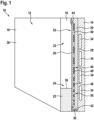
- Fig. 1 shows a vapor chamber arrangement 10 comprising a vapor chamber 12 and a power electronics module 14, which in general may be a heat source 14.
- the vapor chamber 12 comprises a hermetically sealed cavity 16, which is limited by a condenser wall 18 and a baseplate 20. Inside the cavity 16, which also may be seen as an evaporator, a cooling medium 22 is present in liquid and gaseous form, i.e. vapor. Liquid cooling medium 22 collects in a bottom region 24 of the cavity 16.
- the baseplate 20 comprises an evaporator side 26 and an attachment side 28.
- the baseplate 20 is made of a thermally conducting material, such as metal.
- the other components of the vapor chamber, such as the condenser wall 18, may be made of metal.
- the baseplate 20 may be porous, i.e. may contain pores 30. Some of the pores 30 are indicated at the bottom of the baseplate 20, however, the complete baseplate 20 may comprise pores 30. Due to the pores 30, the baseplate 20 acts as a wick and the liquid cooling medium 22 from the bottom region 24 is transported by capillary forces towards a top region 32 of the cavity 16.
- the heat source 14 is attached to the attachment side 28 of the baseplate 20.
- the power electronics module 14 generates heat, in particular via power electronics chips 34, which due to their internal resistance convert some of the processed electric power into heat.
- the heat from the power electronics module 14 is transported by the baseplate 20 from the attachment side 28 to the evaporator side 26.
- the liquid cooling medium is heated and evaporates into vapor, which vapor, i.e. gaseous cooling medium 22, collects above the liquid cooling medium 22 inside the cavity 16.
- a gradient of porosity of the baseplate 20, i.e. the density and/or diameter of the pores 30, may increase from the attachment side 28 to the evaporation side 26. This may support the transfer of heat through the baseplate 20 vertically to the liquid cooling medium transport, and/or the evaporation of the cooling medium 22 at the evaporator side 26.
- the baseplate 20 may have a gradient of increasing porosity from the heat source 14 and/or power electronics module 14 to the liquid cooling medium 22 and/or the cavity 16.
- the heat source 14 and/or power electronics module 14 may be thermally connected to the denser side of the baseplate 20.
- the vapor condenses at the condenser wall 18 and runs down the condenser wall 18 towards the bottom region 24, where the condensed cooling medium 22 collects.
- the condenser wall 18 may be made of a thermally conducting material, such as metal.
- the baseplate 20 has an evaporator side 26 towards the cavity 16 and an attachment side 28 opposite to the evaporator side 26 for attaching the heat source 14, wherein the baseplate 20 is adapted for transferring heat from the attachment side 28 to the cavity 16, such that cooling medium 22 evaporates at the evaporator side 26 and condenses at the condenser wall 18.
- a liquid level 38 separates the liquid cooling medium 22 and the vapor, i.e. gaseous cooling medium 22.
- the baseplate 20 and the condenser wall 18 may be aligned in a vertical direction, such that a liquid level in the cavity 16 is transversal to the baseplate 20 and the condenser wall 18.
- the vapor chamber 12 further comprises a channel 40, with an inlet 42 below a liquid level 38 of the cooling medium 22 and an outlet 44 above the liquid level 38.
- the channel 40 with the inlet 42 and the outlet 44 provides a bubble pump 46 for transporting the liquid medium 22 from the inlet 42 to the outlet 44.
- a bubble pump 46 is integrated into the vapor chamber 12.
- the bubble pump 46 is designed to bring additional liquid cooling medium 22 to the top region 32 and in particular to hot spots situated in the top region 32 of the vapor chamber 12. This may reduce or solve the problem of insufficient capillary porous liquid flow in the baseplate 20 leading to dry-out.
- the bubble pump 46 is adapted to bring liquid cooling medium 22 to a liquid deficient region in the top region 32 of the vapor chamber 12.
- the channel 40 of the bubble pump 46 has a diameter, such that vapor bubbles 48 of the cooling medium 22 forming in the channel 40 transport liquid cooling medium 22 along the channel 40.
- the bubble pump 46 is designed to lift liquid cooling medium 22 to the top region 32 of the cavity 16 by means of confined bubbles 48 that grow only in the flow direction by heat absorption.
- the channel 40 may run at least partially along the vertical direction, which may support the transportation of the liquid cooling medium 22 due to the lower density of the bubbles 48. However, it is also possible that solely the expansion of the bubbles 48 is used for transporting the liquid cooling medium 22 in horizontal sections of the channel 40.
- the inlet 42 which connects the channel 40 to an evaporator liquid pool, i.e. the liquid cooling medium 22 at the bottom, may be situated below a minimal liquid level 38, i.e. the lowest possible liquid level 38.
- the outlet 44 which connects the channel 40 to a vapor space, i.e. a space without liquid cooling medium 22 in the cavity 16 in the top region 32, may be situated above a maximal liquid level 38, i.e. the highest possible liquid level 38.
- the channel 40 may be completely embedded into the baseplate 20, for example may be a through-hole through the baseplate 20. However, in general, the channel 40 may be solely partially embedded into the baseplate 20.
- the channel 40 may be pipe-shaped and solely may be connected to the baseplate 20.
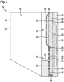
- Fig. 2 shows a further embodiment of a vapor chamber 12, where a channel section 50 having the inlet 42 is partially embedded into the baseplate 20 and a channel section 52 having the outlet 44 is distanced from the baseplate 20.
- the bubble pump 46 and/or the channel 40 is semi-embedded.
- the channel 40 is at least partially connected to the baseplate 20 and is partially embedded into the baseplate 20.
- channel section 50 having the inlet 42 is completely embedded into the baseplate 20.
- a lower fraction of the bubble pump channel 40 is partially or totally embedded into the baseplate 20, in order to ensure the minimal amount of heat transfer required to sufficiently grow the bubbles 48 and thus lift enough liquid cooling medium 22.
- the channel section 52 having the outlet 44 is distanced from the baseplate 20.
- the channel section 52 having the outlet 44 may be pipe-shaped.
- an upper fraction of the bubble pump channel 40 is partially situated in the cavity 16 and is not in contact with the baseplate 20 in order to stop the bubble growth and make sure that there is enough liquid cooling medium 22 left at the outlet 44 of the channel 40.
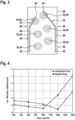
- Fig. 3 shows a schematic view onto the baseplate 20, for example onto the evaporator side 26. It can be seen that there can be more than one bubble pump 46 and/or more than one channel 40.
- the vapor chamber 12 may comprise at least two channels 40 providing a bubble pump 46.
- the number of bubble pumps 46 and/or channels 40 and/or outlets may depend on the number of dry spots to wet with liquid cooling medium 22.
- the heat source 14 may comprise and/or generate several hot spots 54, which have a higher temperature as other parts of the heat source 14.
- the heat source 14 is a power electronics module 14 connected to the baseplate 20 of the vapor chamber 12 and the hot spots 54 are generated by power semiconductor chips 34.
- a hot spot 54 may be an area of the evaporator side 26 with a higher temperature as other areas of the evaporator side 26.
- the one or more outlets 44 of the one or more channels 40 may be arranged, such that they are situated at different hot spots 54.
- an outlet 44 may be situated at each hot spot 54 in a top region 32 of the vapor chamber 12.
- an outlet 44 may be situated outside of the baseplate 20 and may be directed towards a hot spot 54 and/or may end above a hot spot 54.
- liquid cooling medium 22 may be sprayed onto a hot spot 54 and/or may wet a hot spot 54 directly.
- the one or more bubble pumps 46 and/or their channels 40 may be arranged according to a flux density map of the heat source 14 and in particular to the arrangement of hot spots 54.
- a channel section 50 of the channel 40 providing the bubble pump 46 may be arranged besides the hot spots 54 and/or run outside of hot spots 54.
- a fraction of the one or more channels 40, such as the section 50, that is in contact with the baseplate 20 and/or embedded into the baseplate 20 may be placed besides the hot spots 54, so that it still receives heat by conduction but do not hinder the capillary cooling of the lower hot spots 54, i.e. hot spots in the bottom region 24.
- a fraction of the one or more channels 40 that is in a vapor space of the cavity 16, such as the section 52, may have the outlet 44 right above a hot spot 54, so that the liquid cooling medium 22 flowing out of the channel 40 may directly wet this hot spot 54.
- the components of the vapor chamber 12, in particular, the cavity 16, the condenser wall 18, the baseplate 20, optionally the fins 36 and the channel 40, may be made using additive manufacturing.
- Fig. 4 shows the temperature difference between a top and a middle of the cavity 16. In absence of dry-out, the middle of the cavity 16 would be the hottest point of the vapor chamber 12. However, when dry-out occurs, the top becomes the hottest part. Therefore, plotting measurements of this temperature difference allows to characterize a dry-out.
- Fig. 4 shows that using a bubble pump 46 with two channels 40, such as described with respect to Fig. 1-3 , allows to delay a dry-out by about 200 W.
Landscapes
- Engineering & Computer Science (AREA)
- Microelectronics & Electronic Packaging (AREA)
- Physics & Mathematics (AREA)
- Thermal Sciences (AREA)
- Mechanical Engineering (AREA)
- General Engineering & Computer Science (AREA)
- Life Sciences & Earth Sciences (AREA)
- Sustainable Development (AREA)
- Condensed Matter Physics & Semiconductors (AREA)
- General Physics & Mathematics (AREA)
- Computer Hardware Design (AREA)
- Power Engineering (AREA)
- Cooling Or The Like Of Semiconductors Or Solid State Devices (AREA)
- Cooling Or The Like Of Electrical Apparatus (AREA)
Priority Applications (3)
| Application Number | Priority Date | Filing Date | Title |
|---|---|---|---|
| EP23164600.1A EP4439655A1 (de) | 2023-03-28 | 2023-03-28 | Dampfkammer mit integrierter blasenpumpe |
| CN202410233894.2A CN118741943A (zh) | 2023-03-28 | 2024-03-01 | 具有集成气泡泵的均热板 |
| US18/612,272 US20240334662A1 (en) | 2023-03-28 | 2024-03-21 | Vapor chamber with integrated bubble pump |
Applications Claiming Priority (1)
| Application Number | Priority Date | Filing Date | Title |
|---|---|---|---|
| EP23164600.1A EP4439655A1 (de) | 2023-03-28 | 2023-03-28 | Dampfkammer mit integrierter blasenpumpe |
Publications (1)
| Publication Number | Publication Date |
|---|---|
| EP4439655A1 true EP4439655A1 (de) | 2024-10-02 |
Family
ID=85778980
Family Applications (1)
| Application Number | Title | Priority Date | Filing Date |
|---|---|---|---|
| EP23164600.1A Pending EP4439655A1 (de) | 2023-03-28 | 2023-03-28 | Dampfkammer mit integrierter blasenpumpe |
Country Status (3)
| Country | Link |
|---|---|
| US (1) | US20240334662A1 (de) |
| EP (1) | EP4439655A1 (de) |
| CN (1) | CN118741943A (de) |
Citations (3)
| Publication number | Priority date | Publication date | Assignee | Title |
|---|---|---|---|---|
| EP2282624A1 (de) | 2009-08-05 | 2011-02-09 | ABB Research Ltd. | Verdampfer und Kühlkreis |
| JP2011127868A (ja) * | 2009-12-21 | 2011-06-30 | Toyota Industries Corp | 沸騰冷却方法 |
| US20170010049A1 (en) * | 2015-07-09 | 2017-01-12 | Abb Schweiz Ag | Heat exchanger |
-
2023
- 2023-03-28 EP EP23164600.1A patent/EP4439655A1/de active Pending
-
2024
- 2024-03-01 CN CN202410233894.2A patent/CN118741943A/zh active Pending
- 2024-03-21 US US18/612,272 patent/US20240334662A1/en active Pending
Patent Citations (3)
| Publication number | Priority date | Publication date | Assignee | Title |
|---|---|---|---|---|
| EP2282624A1 (de) | 2009-08-05 | 2011-02-09 | ABB Research Ltd. | Verdampfer und Kühlkreis |
| JP2011127868A (ja) * | 2009-12-21 | 2011-06-30 | Toyota Industries Corp | 沸騰冷却方法 |
| US20170010049A1 (en) * | 2015-07-09 | 2017-01-12 | Abb Schweiz Ag | Heat exchanger |
Also Published As
| Publication number | Publication date |
|---|---|
| CN118741943A (zh) | 2024-10-01 |
| US20240334662A1 (en) | 2024-10-03 |
Similar Documents
| Publication | Publication Date | Title |
|---|---|---|
| US10820454B2 (en) | Vapor chamber heat spreaders with engineered vapor and liquid flow paths | |
| US7431071B2 (en) | Fluid circuit heat transfer device for plural heat sources | |
| US20190357378A1 (en) | Two-phase immersion cooling system and method with enhanced circulation of vapor flow through a condenser | |
| US7434308B2 (en) | Cooling of substrate using interposer channels | |
| US5396947A (en) | Radiating device | |
| CN101142459B (zh) | 带有热管增强托板的射频功率放大器组件 | |
| US6615912B2 (en) | Porous vapor valve for improved loop thermosiphon performance | |
| JP5589666B2 (ja) | 半導体装置 | |
| NO168150B (no) | Elektronisk modul med selvdrevet kjoeleanordning | |
| US20130020053A1 (en) | Low-profile heat-spreading liquid chamber using boiling | |
| US7093647B2 (en) | Ebullition cooling device for heat generating component | |
| KR20020093897A (ko) | 마이크로 열 교환기를 장착한 파워 전자 장치의 부품냉각을 위한 냉각장치 | |
| JP2013245875A (ja) | 冷却装置及び電子装置 | |
| US11369042B2 (en) | Heat exchanger with integrated two-phase heat spreader | |
| US20180270993A1 (en) | Cooling using a wick with varied thickness | |
| EP4439655A1 (de) | Dampfkammer mit integrierter blasenpumpe | |
| JP3900702B2 (ja) | 沸騰冷却装置 | |
| WO2019204339A1 (en) | Phase separator and liquid re-saturator for two-phase cooling | |
| CN106409790B (zh) | 一种强效的芯片散热器 | |
| JP2828996B2 (ja) | 半導体の冷却装置 | |
| KR101172679B1 (ko) | 공기조화기의 실외기 | |
| CN117249498A (zh) | 散热器和空调室外机 | |
| RU2006139625A (ru) | Устройство для нагрева и охлаждения статических преобразователей | |
| KR102183239B1 (ko) | Tgp 유닛, tgp 유닛 일체형 히트싱크 및 tgp 유닛의 제조방법 | |
| JP5163548B2 (ja) | 沸騰冷却装置 |
Legal Events
| Date | Code | Title | Description |
|---|---|---|---|
| PUAI | Public reference made under article 153(3) epc to a published international application that has entered the european phase |
Free format text: ORIGINAL CODE: 0009012 |
|
| STAA | Information on the status of an ep patent application or granted ep patent |
Free format text: STATUS: THE APPLICATION HAS BEEN PUBLISHED |
|
| AK | Designated contracting states |
Kind code of ref document: A1 Designated state(s): AL AT BE BG CH CY CZ DE DK EE ES FI FR GB GR HR HU IE IS IT LI LT LU LV MC ME MK MT NL NO PL PT RO RS SE SI SK SM TR |
|
| STAA | Information on the status of an ep patent application or granted ep patent |
Free format text: STATUS: REQUEST FOR EXAMINATION WAS MADE |
|
| 17P | Request for examination filed |
Effective date: 20250124 |