EP4439636A2 - Film peeling apparatus and film peeling method - Google Patents
Film peeling apparatus and film peeling method Download PDFInfo
- Publication number
- EP4439636A2 EP4439636A2 EP24160190.5A EP24160190A EP4439636A2 EP 4439636 A2 EP4439636 A2 EP 4439636A2 EP 24160190 A EP24160190 A EP 24160190A EP 4439636 A2 EP4439636 A2 EP 4439636A2
- Authority
- EP
- European Patent Office
- Prior art keywords
- rod
- film
- moving member
- contact portion
- protective film
- Prior art date
- Legal status (The legal status is an assumption and is not a legal conclusion. Google has not performed a legal analysis and makes no representation as to the accuracy of the status listed.)
- Granted
Links
Images


Classifications
-
- B—PERFORMING OPERATIONS; TRANSPORTING
- B32—LAYERED PRODUCTS
- B32B—LAYERED PRODUCTS, i.e. PRODUCTS BUILT-UP OF STRATA OF FLAT OR NON-FLAT, e.g. CELLULAR OR HONEYCOMB, FORM
- B32B43/00—Operations specially adapted for layered products and not otherwise provided for, e.g. repairing; Apparatus therefor
- B32B43/006—Delaminating
-
- B—PERFORMING OPERATIONS; TRANSPORTING
- B65—CONVEYING; PACKING; STORING; HANDLING THIN OR FILAMENTARY MATERIAL
- B65H—HANDLING THIN OR FILAMENTARY MATERIAL, e.g. SHEETS, WEBS, CABLES
- B65H41/00—Machines for separating superposed webs
-
- H—ELECTRICITY
- H10—SEMICONDUCTOR DEVICES; ELECTRIC SOLID-STATE DEVICES NOT OTHERWISE PROVIDED FOR
- H10P—GENERIC PROCESSES OR APPARATUS FOR THE MANUFACTURE OR TREATMENT OF DEVICES COVERED BY CLASS H10
- H10P72/00—Handling or holding of wafers, substrates or devices during manufacture or treatment thereof
- H10P72/04—Apparatus for manufacture or treatment
- H10P72/0442—Apparatus for placing on an insulating substrate, e.g. tape
-
- B—PERFORMING OPERATIONS; TRANSPORTING
- B65—CONVEYING; PACKING; STORING; HANDLING THIN OR FILAMENTARY MATERIAL
- B65B—MACHINES, APPARATUS OR DEVICES FOR, OR METHODS OF, PACKAGING ARTICLES OR MATERIALS; UNPACKING
- B65B69/00—Unpacking of articles or materials, not otherwise provided for
-
- H—ELECTRICITY
- H01—ELECTRIC ELEMENTS
- H01M—PROCESSES OR MEANS, e.g. BATTERIES, FOR THE DIRECT CONVERSION OF CHEMICAL ENERGY INTO ELECTRICAL ENERGY
- H01M8/00—Fuel cells; Manufacture thereof
- H01M8/24—Grouping of fuel cells, e.g. stacking of fuel cells
- H01M8/2404—Processes or apparatus for grouping fuel cells
-
- B—PERFORMING OPERATIONS; TRANSPORTING
- B65—CONVEYING; PACKING; STORING; HANDLING THIN OR FILAMENTARY MATERIAL
- B65H—HANDLING THIN OR FILAMENTARY MATERIAL, e.g. SHEETS, WEBS, CABLES
- B65H2701/00—Handled material; Storage means
- B65H2701/10—Handled articles or webs
- B65H2701/17—Nature of material
- B65H2701/175—Plastic
- B65H2701/1752—Polymer film
-
- H—ELECTRICITY
- H10—SEMICONDUCTOR DEVICES; ELECTRIC SOLID-STATE DEVICES NOT OTHERWISE PROVIDED FOR
- H10P—GENERIC PROCESSES OR APPARATUS FOR THE MANUFACTURE OR TREATMENT OF DEVICES COVERED BY CLASS H10
- H10P72/00—Handling or holding of wafers, substrates or devices during manufacture or treatment thereof
- H10P72/70—Handling or holding of wafers, substrates or devices during manufacture or treatment thereof for supporting or gripping
- H10P72/78—Handling or holding of wafers, substrates or devices during manufacture or treatment thereof for supporting or gripping using vacuum or suction, e.g. Bernoulli chucks
-
- Y—GENERAL TAGGING OF NEW TECHNOLOGICAL DEVELOPMENTS; GENERAL TAGGING OF CROSS-SECTIONAL TECHNOLOGIES SPANNING OVER SEVERAL SECTIONS OF THE IPC; TECHNICAL SUBJECTS COVERED BY FORMER USPC CROSS-REFERENCE ART COLLECTIONS [XRACs] AND DIGESTS
- Y02—TECHNOLOGIES OR APPLICATIONS FOR MITIGATION OR ADAPTATION AGAINST CLIMATE CHANGE
- Y02E—REDUCTION OF GREENHOUSE GAS [GHG] EMISSIONS, RELATED TO ENERGY GENERATION, TRANSMISSION OR DISTRIBUTION
- Y02E60/00—Enabling technologies; Technologies with a potential or indirect contribution to GHG emissions mitigation
- Y02E60/30—Hydrogen technology
- Y02E60/50—Fuel cells
-
- Y—GENERAL TAGGING OF NEW TECHNOLOGICAL DEVELOPMENTS; GENERAL TAGGING OF CROSS-SECTIONAL TECHNOLOGIES SPANNING OVER SEVERAL SECTIONS OF THE IPC; TECHNICAL SUBJECTS COVERED BY FORMER USPC CROSS-REFERENCE ART COLLECTIONS [XRACs] AND DIGESTS
- Y10—TECHNICAL SUBJECTS COVERED BY FORMER USPC
- Y10T—TECHNICAL SUBJECTS COVERED BY FORMER US CLASSIFICATION
- Y10T156/00—Adhesive bonding and miscellaneous chemical manufacture
- Y10T156/11—Methods of delaminating, per se; i.e., separating at bonding face
- Y10T156/1126—Using direct fluid current against work during delaminating
- Y10T156/1132—Using vacuum directly against work during delaminating
-
- Y—GENERAL TAGGING OF NEW TECHNOLOGICAL DEVELOPMENTS; GENERAL TAGGING OF CROSS-SECTIONAL TECHNOLOGIES SPANNING OVER SEVERAL SECTIONS OF THE IPC; TECHNICAL SUBJECTS COVERED BY FORMER USPC CROSS-REFERENCE ART COLLECTIONS [XRACs] AND DIGESTS
- Y10—TECHNICAL SUBJECTS COVERED BY FORMER USPC
- Y10T—TECHNICAL SUBJECTS COVERED BY FORMER US CLASSIFICATION
- Y10T156/00—Adhesive bonding and miscellaneous chemical manufacture
- Y10T156/19—Delaminating means
- Y10T156/1928—Differential fluid pressure delaminating means
- Y10T156/1944—Vacuum delaminating means [e.g., vacuum chamber, etc.]
Definitions
- the present invention relates to a film peeling apparatus and a film peeling method which peel a film from a workpiece to which the film is tightly adhered.
- a device that peels off a protective sheet from a prepreg sheet to which the protective sheet is attached is known.
- Such a device is disclosed, for example, in JP 2020-109046 A .
- air is injected to the end surface of the prepreg sheet to peel off the protective sheet from the prepreg sheet.
- An aspect of the present invention is a film peeling apparatus peeling a film from a workpiece to which the film is tightly adhered.
- the film peeling apparatus includes: a moving member disposed above a placement member on which the workpiece is placed so as to be vertically movable between a first position and a second position above the first position; a first rod extending downward from the moving member toward the placement member and having a first contact portion at a lower end portion of the first rod that contacts an upper surface of the film when the moving member is located at the first position; a second rod extending downward from the moving member toward the placement member and having a second contact portion at a lower end portion of the second rod that contacts the upper surface of the film when the moving member is located at the first position; and a support portion configured to support the first rod and the second rod from the moving member such that the first rod and the second rod move in a vertical direction with a movement of the moving member in the vertical direction.
- the first contact portion has a suction portion that sucks the film
- the second contact portion has a sliding portion so that the film can be moved in a horizontal direction while the film is pressed by the second rod, and when the moving member moves from the first position to the second position, the support portion supports the first rod and the second rod so that the second rod starts to rise after the first rod starts to rise.
- a film peeling apparatus peels and removes a protective film from a surface of a workpiece to which the protective film has been attached in advance.
- the workpiece is, for example, a resin frame to be incorporated into a fuel cell stack that is a component of a fuel cell.
- This frame supports an assembly of an electrolyte membrane and anode and cathode electrodes disposed on both sides of the electrolyte membrane, that is, a membrane electrode assembly (MEA), and is also called a sub-gasket.
- MEA membrane electrode assembly
- FIG. 1 schematically illustrates an overall configuration of a film peeling apparatus 100 according to an embodiment of the present invention.
- the film peeling apparatus 100 includes an industrial robot 10 having articulated arms 11 and 12 and a hand 13 provided at the end of the arm 12, a support plate 20 attached to the hand 13, and a plurality of rods 30 supported by the support plate 20.
- the arms 11 and 12 are rotatably connected via a rotary shaft 10a, and the arm 12 and the hand 13 are rotatably connected via a rotary shaft 10b.
- the arms 11 and 12 and the hand 13 are rotated by the drive of an actuator 14 such as a servo motor provided on the rotary shafts 10a and 10b, for example, which changes the position and posture of the hand 13.
- the actuator 14 is controlled by an ECU 15.
- the ECU 15 is an electronic control unit including a computer having CPU, ROM, RAM and other peripheral circuits.
- the support plate 20 is fixed to the plate 13a at the end of the hand 13 via a spacer 13b. Therefore, the support plate 20 is provided in substantially parallel with the plate 13a, separated from the plate 13a by a predetermined distance, and moves together with the hand 13. Therefore, the position and posture of the support plate 20 can be controlled by the ECU 15. Specifically, the support plate 20 can be moved in the direction of an arrow Z, that is, raised or lowered in the vertical direction, while the support plate 20 is held in the horizontal posture illustrated in FIG. 1 .
- the rods 30 extend in a direction substantially perpendicular to the support plate 20, in other words, in a vertical direction with respect to the support plate 20 in a horizontal posture.
- a pad 40 is provided at the lower end portion of each of the rods 30.
- the pad 40 includes a suction pad that sucks an object 200, such as a workpiece 201 and a protective film 202.
- the rods 30 of the suction pads are configured in a cylindrical shape and their internal passages are connected to a vacuum generator, and a negative pressure (vacuum pressure) is generated in the suction pads via the vacuum generator, so that the object 200 can be sucked.
- FIG. 1 illustrates the support plate 20 in a horizontal posture on which the protective film 202 is sucked.
- the support plate 20 is raised and lowered above a tray 300 whose upper surface is opened.
- the tray 300 stores the workpieces 201 in a stacked state, and the tray 300 constitutes a platform for the workpieces 201.
- the protective films 202 are attached between the workpieces 201, and the workpieces 201 and the protective films 202 are alternately stacked.
- the protective films 202 are flexible, bendable, thin resin films such as polyethylene naphthalate. In the tray 300, the protective films 202 are tightly adhered to the surfaces of the workpieces 201.
- FIG. 2A is a plan view (arrow view IIA in FIG. 1 ) illustrating the inside of the tray after a protective film 202 is separated from the surface of a workpiece 201.
- the workpiece 201 is disposed at the uppermost portion of the tray 300.
- the workpiece 201 is a substantially rectangular resin frame that supports the membrane electrode assembly of the fuel cell.
- a substantially rectangular opening 204 is provided in the center of the workpiece 201. After the workpiece 201 is taken out from the tray 300, a membrane electrode assembly is formed so as to cover the opening 204.
- the workpiece 201 is also provided with a plurality of through holes 205 that constitute flow paths for supplying and discharging fuel gas, oxidant gas, and cooling medium.
- the workpiece 201 had the opening 204 and the through holes 205. Therefore, when the workpiece 201 is located at the uppermost portion of the tray 300 ( FIG. 2A ), the protective film 202 below the workpiece 201 can be pressed from above by holding pads (not illustrated) via the opening 204 and the through holes 205. Then, vacuum breakdown can be caused at the interface between the workpiece 201 and the protective film 202 by sucking the workpiece 201 with the suction pads while pressing down on the protective film 202 with the holding pads, which allows the workpiece 201 and the protective film 202 to be separated. When the workpiece 201 is disposed in the tray 300, the workpiece 201 may not have the through holes 205.
- the present embodiment configures the film peeling apparatus 100 as follows.
- the film peeling apparatus 100 includes three types of rods and pads that operate differently from each other.
- the three types of rods are referred to as the suction rod, first holding rod, and second holding rod for convenience, and the pads at the ends of the suction rod, first holding rod, and second holding rod are referred to as the suction pad, first holding pad, and second holding pad, respectively.
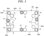
- FIG. 3 illustrates the positions of the pads 40 (suction pads 41, first holding pads 42, and second holding pads 43) that are in contact with the upper surface of the protective film 202.
- the suction pads 41 are indicated by circles, the first holding pads 42 by double circles, and the second holding pads 43 by triple circles.
- the protective film 202 has four corner portions 202a and four sides (edge portions 202b).
- a first holding pad 42 is disposed inside each of the four corner portions 202a. More specifically, the first holding pads 42 are disposed on the diagonal line (not illustrated) connecting the corner portions 202a and 202a and in proximity to the edge portion 202b of the protective film 202.
- a suction pad 41 is disposed adjacent to the first holding pad 42.
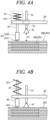
- FIG. 4A is a schematic view of the configuration of the suction rod 31 and the first holding rod 32, that is, a side view of an area IV in FIG. 3 .
- FIG. 4A is a view illustrating the middle of the lowering operation of the support plate 20, and illustrates the point in time at which the first holding pads 42 start to contact the protective film 202.
- the suction rod 31 extends vertically through the support plate 20 and is supported by the support plate 20 via a support portion 21.
- the support portion 21 is a fixing portion that fixedly supports the suction rod 31 on the support plate 20, and fixes, for example, a flange portion extending in the horizontal direction from the outer peripheral surface of the suction rod 31 to the upper surface of the support plate 20 via a bolt.
- the support portion 21 may be configured by a joining means such as welding, and the suction rod 31 may be fixed to the support plate 20 via the joining means.
- the suction rod 31 is formed in a cylindrical shape and has an internal passage extending in the vertical direction. The internal passage connects to a vacuum generator (not illustrated).
- the suction pad 41 is made of a member having elasticity such as rubber or resin.
- the suction pad 41 has a through hole from the upper end surface to the lower end surface, and the through hole connects to the vacuum generator via the internal passage of the suction rod 31.
- the lower end surface of the suction pad 41 is a suction surface that sucks the object 200 such as the workpiece 201 or protective film 202.
- Turning the vacuum generator on and off includes opening and closing a solenoid valve provided in the middle of a flow path connecting the vacuum generator and the internal passage of the suction rod 31.
- the turning on/off of the vacuum generator (for example, opening/closing of the solenoid valve) is controlled by the ECU 15 ( FIG. 1 ).
- the first holding rod 32 extends vertically through the support plate 20, and is supported by the support plate 20 via the support portion 22.
- the support portion 22 includes a spring 221, and supports the first holding rod 32 via the spring 221 so that it can move vertically relative to the support plate 20.
- the spring 221 is, for example, a tension coil spring disposed around the first holding rod 32 above the support plate 20.
- the upper end portion of the spring 221 is connected to the upper end portion of the first holding rod 32, and the lower end portion is connected to the upper surface of the support plate 20.
- FIG. 4A illustrates an initial state in which no biasing force acts on the spring 221, and the length of the spring 221 is a free length.
- the first holding pad 42 has a sliding portion 421 such that the protective film 202 can move (slide) in the horizontal direction along the upper surface of the workpiece 201 while the protective film 202 is pressed by the first holding rod 32.
- the sliding portion 421 includes a ball or a roller that is rotatably supported by a case member 420 at the end of the first holding pad 42 via a rotating shaft extending in the horizontal direction.
- the lower end of the first holding pad 42 (sliding portion 421) is located below the lower end of the suction pad 41 by a predetermined length Z1.
- the support plate 20 is lowered from the initial state illustrated in FIG. 4A .
- the suction rod 31 descends together with the support plate 20 while the position of the first holding rod 32 remains constant.
- the protective film 202 moves in the horizontal direction (toward the suction pad side) while sliding along the upper surface of the workpiece 201 below the sliding portion 421.
- the ball or roller of the sliding portion 421 rotates, which promotes the movement of the protective film 202 while the protective film 202 is pressed by the first holding pad 42.
- the end portion (corner portion 202a) of the protective film 202 is located below the first holding pad 42.
- the suction pads 41 and the second holding pads 43 are disposed side by side along the edge portions 202b. Therefore, as illustrated in the area V, a pair of suction pads 41 are disposed on both sides of a second holding pad 43, and the second holding pad 43 is located outside of a virtual line L1 connecting the pair of suction pads 41 (on the edge side of the protective film 202).
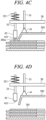
- FIG. 5A is a schematic view of the configuration of the suction rods 31 and the second holding rod 33, that is, a side view of the area V in FIG. 3 .
- FIG. 5A is a view illustrating the middle of the lowering operation of the support plate 20, and illustrates the point in time at which the second holding pad 43 starts to contact the protective film 202
- the second holding pad 43 is closer to one of the pair of suction pads 41, but FIG. 5A illustrates the second holding pad 43 as being located in the middle of the pair of suction pads 41 for convenience.
- the second holding rod 33 extends vertically through the support plate 20 and is supported by the support plate 20 via a support portion 23.
- the support portion 23 includes a spring 231, and supports the second holding rod 33 via the spring 231 so that it can move vertically relative to the support plate 20.
- the spring 231 is, for example, a tension coil spring disposed around the second holding rod 33 above the support plate 20.
- the upper end portion of the spring 231 is connected to the upper end portion of the second holding rod 33, and the lower end portion is connected to the upper surface of the support plate 20.
- FIG. 5A illustrates an initial state in which no biasing force acts on the spring 231, and the length of the spring 231 is a free length.
- the second holding pad 43 includes an elastic body 431 so that the protective film 202 can be displaced while the protective film 202 is pressed by the second holding rod 33.
- the elastic body 431 is made of rubber, resin, or the like.
- the predetermined length Z2 is shorter than the predetermined length Z1 ( FIG. 4A ). Note that Z2 may be equal to Z1.
- the support plate 20 is lowered from the initial state illustrated in FIG. 5A .
- the suction rods 31 descend together with the support plate 20 while the position of the second holding rod 33 remains constant.
- the suction pads 41 are raised.
- the second holding pad 43 remains in contact with the protective film 202 due to the biasing force of the spring 231.
- a tensile force acts on the protective film 202 while the elastic body 431 of the second holding pad 43 is elastically deformed, which causes vacuum breakdown at the interface between the workpiece 201 and the protective film 202, allowing air to infiltrate the interface.
- the operation of the film peeling apparatus 100 according to the present embodiment is summarized as follows.
- the following operation represents the step of peeling the protective film 202 by the film peeling method according to the present embodiment.
- the robot 10 is driven by a command from the ECU 15, and the support plate 20 is moved to the initial position above the tray 300 in a horizontal posture (initial moving step).
- the support plate 20 is lowered by the drive of the robot 10 until the suction pads 41, the first holding pads 42, and the second holding pads 43 contact the upper surface of the protective film 202 (lowering step). At this time, first the first holding pads 42, then the second holding pads 43, and finally the suction pads 41 contact the protective film 202.
- the position of the support plate 20 in a state where all the pads 41 to 43 are in contact with the protective film 202 may be referred to as a first position.
- the initial position of the support plate 20 before it is lowered may be referred to as a second position.
- the support plate 20 is provided to be movable between the first and second positions.
- FIG. 7 illustrates the moving amount of the pads 40 over time from the start point in time of the raising step.
- the characteristic f0 corresponds to the moving amount of the suction pads 41
- the characteristic f1 corresponds to the moving amount of the first holding pads 42
- the characteristic f2 corresponds to the moving amount of the second holding pads 43.
- the protective film 202 rises while being pressed by the second holding pads 43, vacuum breakdown occurs in the areas AR1 between the suction pads 41 and the second holding pads 43, causing air to infiltrate the areas AR1 ( FIG. 6 ).
- the second holding pads 43 start to rise ( FIG. 5C ).
- the suction pads 41 and the second holding pads 43 rise while the first holding pads 42 press the protective film 202 by the biasing force of the spring 221.
- the first holding pads 42 start to rise ( FIG. 4C ).
- the protective film 202 can be easily peeled off from the workpiece 201.
- the support plate 20 (moving member) is raised and lowered above the tray 300 (placement member) using the articulated robot 10, but the moving member may be supported so as to be vertically movable using a device other than the robot.
- the moving member may be supported so as to be vertically movable along a frame body erected in the vertical direction.
- the moving member is configured with the support plate 20, but the moving member may be other than the plate.
- the film peeling apparatus 100 includes the suction rod 31 (first rod) having the suction pad 41 (first contact portion) at its lower end portion, the first holding rod 32 (second rod) having the first holding pad 42 (second contact portion) at its lower end, and the second holding rod 33 (third rod) having the second holding pad 43 (third contact portion) at its lower end, but the third rod may be omitted.
- a vacuum generator is connected to the suction pads 41 to suck the protective film 202, but the configuration of the suction portions is not limited to that described above.
- the sliding portion 421 of the first holding pad 42 is configured with a rotatable ball or roller, but the configuration of the sliding portion is not limited to the above-described configuration.
- a highly conductive roller or ionizer may be used in the sliding portion to obtain a function of removing static electricity.
- the support portion 22 supports the first holding rod 32 so as to be vertically movable with respect to the support plate 20 via the spring 221 (first spring), but the configuration of the movable support portion (first movable support portion) is not limited to the above-described configuration.
- the support portion 23 supports the second holding rod 33 so as to be vertically movable with respect to the support plate 20 via the spring 231 (second spring), but the configuration of the second movable support portion is not limited to the above-described configuration.
- the above embodiment describes an example of peeling off the protective film 202 tightly adhered to the surface of the workpiece 201, using a resin frame constituting a membrane electrode assembly of a fuel cell as the workpiece 201, but the present invention can be similarly applied to peeling off a film from another workpiece to which the film is tightly adhered.
- the film tightly adhered to the workpiece can be easily peeled off with a simple configuration.
Landscapes
- Engineering & Computer Science (AREA)
- Mechanical Engineering (AREA)
- Life Sciences & Earth Sciences (AREA)
- Manufacturing & Machinery (AREA)
- Sustainable Development (AREA)
- Sustainable Energy (AREA)
- Chemical & Material Sciences (AREA)
- Chemical Kinetics & Catalysis (AREA)
- Electrochemistry (AREA)
- General Chemical & Material Sciences (AREA)
- Folding Of Thin Sheet-Like Materials, Special Discharging Devices, And Others (AREA)
- Container, Conveyance, Adherence, Positioning, Of Wafer (AREA)
Abstract
Description
- The present invention relates to a film peeling apparatus and a film peeling method which peel a film from a workpiece to which the film is tightly adhered.
- As a conventional device of this type, a device that peels off a protective sheet from a prepreg sheet to which the protective sheet is attached is known. Such a device is disclosed, for example, in
JP 2020-109046 A JP 2020 - 109046 A - However, it is difficult to peel off the film adhered to the workpiece with a configuration that injects air, as in the device described in
JP 2020-109046 A - An aspect of the present invention is a film peeling apparatus peeling a film from a workpiece to which the film is tightly adhered. The film peeling apparatus includes: a moving member disposed above a placement member on which the workpiece is placed so as to be vertically movable between a first position and a second position above the first position; a first rod extending downward from the moving member toward the placement member and having a first contact portion at a lower end portion of the first rod that contacts an upper surface of the film when the moving member is located at the first position; a second rod extending downward from the moving member toward the placement member and having a second contact portion at a lower end portion of the second rod that contacts the upper surface of the film when the moving member is located at the first position; and a support portion configured to support the first rod and the second rod from the moving member such that the first rod and the second rod move in a vertical direction with a movement of the moving member in the vertical direction. The first contact portion has a suction portion that sucks the film, the second contact portion has a sliding portion so that the film can be moved in a horizontal direction while the film is pressed by the second rod, and when the moving member moves from the first position to the second position, the support portion supports the first rod and the second rod so that the second rod starts to rise after the first rod starts to rise.
- The objects, features, and advantages of the present invention will become clearer from the following description of embodiments in relation to the attached drawings, in which:
-
FIG. 1 is a diagram schematically illustrating an overall configuration of a film peeling apparatus according to an embodiment of the present invention; -
FIG. 2A is an arrow view IIA inFIG. 1 ; -
FIG. 2B is a diagram shownFIG. 2A from the opposite side; -
FIG. 3 is a diagram illustrating positions of the pads included in the film peeling apparatus inFIG. 1 ; -
FIG. 4A is a diagram illustrating a schematic configuration of the suction rod and the first holding rod included the film peeling apparatus inFIG. 1 and an example of operation of the suction rod and the first holding rod; -
FIG. 4B is a diagram illustrating an example of subsequent operation afterFIG. 4A ; -
FIG. 4C is a diagram illustrating an example of subsequent operation afterFIG. 4B ; -
FIG. 4D is a diagram illustrating an example of subsequent operation afterFIG. 4C ; -
FIG. 5A is a diagram illustrating a schematic configuration of the suction rod and the second holding rod included the film peeling apparatus inFIG. 1 and an example of operation of the suction rod and the second holding rod; -
FIG. 5B is a diagram illustrating an example of subsequent operation afterFIG. 5A ; -
FIG. 5C is a diagram illustrating an example of subsequent operation afterFIG. 5B ; -
FIG. 6 is a diagram illustrating the operation corresponding toFIG. 5C on a protective film; and -
FIG. 7 is a diagram illustrating moving amount of the pads over time of raising step by a film peeling method according to the embodiment of the present invention. - Hereinafter, an embodiment of the present invention will be described with reference to
FIGS. 1 to 7 . A film peeling apparatus according to an embodiment of the present invention peels and removes a protective film from a surface of a workpiece to which the protective film has been attached in advance. The workpiece is, for example, a resin frame to be incorporated into a fuel cell stack that is a component of a fuel cell. - This frame supports an assembly of an electrolyte membrane and anode and cathode electrodes disposed on both sides of the electrolyte membrane, that is, a membrane electrode assembly (MEA), and is also called a sub-gasket. By alternately stacking a frame integrated with the assembly and a metal separator in a predetermined number of layers, a fuel cell stack containing a plurality of power generation cells is configured.
-
FIG. 1 schematically illustrates an overall configuration of afilm peeling apparatus 100 according to an embodiment of the present invention. As illustrated inFIG. 1 , thefilm peeling apparatus 100 includes anindustrial robot 10 having articulatedarms hand 13 provided at the end of thearm 12, asupport plate 20 attached to thehand 13, and a plurality ofrods 30 supported by thesupport plate 20. - The
arms rotary shaft 10a, and thearm 12 and thehand 13 are rotatably connected via arotary shaft 10b. Note that the configuration of the robot 10 (the number of arms and the like) is not limited to that illustrated in the figure. Thearms hand 13 are rotated by the drive of anactuator 14 such as a servo motor provided on therotary shafts hand 13. Theactuator 14 is controlled by anECU 15. The ECU 15 is an electronic control unit including a computer having CPU, ROM, RAM and other peripheral circuits. - The
support plate 20 is fixed to theplate 13a at the end of thehand 13 via aspacer 13b. Therefore, thesupport plate 20 is provided in substantially parallel with theplate 13a, separated from theplate 13a by a predetermined distance, and moves together with thehand 13. Therefore, the position and posture of thesupport plate 20 can be controlled by theECU 15. Specifically, thesupport plate 20 can be moved in the direction of an arrow Z, that is, raised or lowered in the vertical direction, while thesupport plate 20 is held in the horizontal posture illustrated inFIG. 1 . - The
rods 30 extend in a direction substantially perpendicular to thesupport plate 20, in other words, in a vertical direction with respect to thesupport plate 20 in a horizontal posture. Apad 40 is provided at the lower end portion of each of therods 30. Thepad 40 includes a suction pad that sucks an object 200, such as aworkpiece 201 and aprotective film 202. Therods 30 of the suction pads are configured in a cylindrical shape and their internal passages are connected to a vacuum generator, and a negative pressure (vacuum pressure) is generated in the suction pads via the vacuum generator, so that the object 200 can be sucked.FIG. 1 illustrates thesupport plate 20 in a horizontal posture on which theprotective film 202 is sucked. - The
support plate 20 is raised and lowered above atray 300 whose upper surface is opened. Thetray 300 stores theworkpieces 201 in a stacked state, and thetray 300 constitutes a platform for theworkpieces 201. Theprotective films 202 are attached between theworkpieces 201, and theworkpieces 201 and theprotective films 202 are alternately stacked. Theprotective films 202 are flexible, bendable, thin resin films such as polyethylene naphthalate. In thetray 300, theprotective films 202 are tightly adhered to the surfaces of theworkpieces 201. -
FIG. 2A is a plan view (arrow view IIA inFIG. 1 ) illustrating the inside of the tray after aprotective film 202 is separated from the surface of aworkpiece 201. As illustrated inFIG. 2A , theworkpiece 201 is disposed at the uppermost portion of thetray 300. As described above, theworkpiece 201 is a substantially rectangular resin frame that supports the membrane electrode assembly of the fuel cell. A substantiallyrectangular opening 204 is provided in the center of theworkpiece 201. After theworkpiece 201 is taken out from thetray 300, a membrane electrode assembly is formed so as to cover theopening 204. Theworkpiece 201 is also provided with a plurality of throughholes 205 that constitute flow paths for supplying and discharging fuel gas, oxidant gas, and cooling medium. - As described above, the
workpiece 201 had theopening 204 and the throughholes 205. Therefore, when theworkpiece 201 is located at the uppermost portion of the tray 300 (FIG. 2A ), theprotective film 202 below theworkpiece 201 can be pressed from above by holding pads (not illustrated) via theopening 204 and the throughholes 205. Then, vacuum breakdown can be caused at the interface between theworkpiece 201 and theprotective film 202 by sucking theworkpiece 201 with the suction pads while pressing down on theprotective film 202 with the holding pads, which allows theworkpiece 201 and theprotective film 202 to be separated. When theworkpiece 201 is disposed in thetray 300, theworkpiece 201 may not have the throughholes 205. - On the other hand, when the
protective film 202 is located at the uppermost portion of the tray 300 (FIG. 2B ), since theprotective film 202 has no through holes, theworkpiece 201 below theprotective film 202 cannot be pressed by the holding pads from above. This makes it difficult to peel the tightly adheredprotective film 202 from theworkpiece 201, and if theprotective film 202 is raised via the suction pads, theworkpiece 201 may also be raised with it. Therefore, in order to enable easy peeling of theprotective film 202 even in the case illustrated inFIG. 2B , the present embodiment configures thefilm peeling apparatus 100 as follows. - The
film peeling apparatus 100 according to the present embodiment includes three types of rods and pads that operate differently from each other. Hereinafter, the three types of rods are referred to as the suction rod, first holding rod, and second holding rod for convenience, and the pads at the ends of the suction rod, first holding rod, and second holding rod are referred to as the suction pad, first holding pad, and second holding pad, respectively. -
FIG. 3 illustrates the positions of the pads 40 (suction pads 41, first holdingpads 42, and second holding pads 43) that are in contact with the upper surface of theprotective film 202. In the figure, thesuction pads 41 are indicated by circles, thefirst holding pads 42 by double circles, and thesecond holding pads 43 by triple circles. - First, the relationship between a
suction rod 31 and afirst holding rod 32 will be described. As illustrated inFIG. 3 , theprotective film 202 has fourcorner portions 202a and four sides (edgeportions 202b). Afirst holding pad 42 is disposed inside each of the fourcorner portions 202a. More specifically, thefirst holding pads 42 are disposed on the diagonal line (not illustrated) connecting thecorner portions edge portion 202b of theprotective film 202. Inside each of the first holding pads 42 (the opposite side of thecorner portion 202a), asuction pad 41 is disposed adjacent to thefirst holding pad 42. -
FIG. 4A is a schematic view of the configuration of thesuction rod 31 and the first holdingrod 32, that is, a side view of an area IV inFIG. 3 .FIG. 4A is a view illustrating the middle of the lowering operation of thesupport plate 20, and illustrates the point in time at which thefirst holding pads 42 start to contact theprotective film 202. - As illustrated in
FIG. 4A , thesuction rod 31 extends vertically through thesupport plate 20 and is supported by thesupport plate 20 via asupport portion 21. Thesupport portion 21 is a fixing portion that fixedly supports thesuction rod 31 on thesupport plate 20, and fixes, for example, a flange portion extending in the horizontal direction from the outer peripheral surface of thesuction rod 31 to the upper surface of thesupport plate 20 via a bolt. Thesupport portion 21 may be configured by a joining means such as welding, and thesuction rod 31 may be fixed to thesupport plate 20 via the joining means. Thesuction rod 31 is formed in a cylindrical shape and has an internal passage extending in the vertical direction. The internal passage connects to a vacuum generator (not illustrated). - The
suction pad 41 is made of a member having elasticity such as rubber or resin. Thesuction pad 41 has a through hole from the upper end surface to the lower end surface, and the through hole connects to the vacuum generator via the internal passage of thesuction rod 31. The lower end surface of thesuction pad 41 is a suction surface that sucks the object 200 such as theworkpiece 201 orprotective film 202. When the vacuum generator is turned on to create a vacuum inside the through hole, a suction force acts on the object 200, and the object 200 can be sucked. When the vacuum generator is turned off, the suction force is removed and the object 200 can be released from the suction surface. Turning the vacuum generator on and off includes opening and closing a solenoid valve provided in the middle of a flow path connecting the vacuum generator and the internal passage of thesuction rod 31. The turning on/off of the vacuum generator (for example, opening/closing of the solenoid valve) is controlled by the ECU 15 (FIG. 1 ). - The
first holding rod 32 extends vertically through thesupport plate 20, and is supported by thesupport plate 20 via thesupport portion 22. Thesupport portion 22 includes aspring 221, and supports the first holdingrod 32 via thespring 221 so that it can move vertically relative to thesupport plate 20. Thespring 221 is, for example, a tension coil spring disposed around the first holdingrod 32 above thesupport plate 20. The upper end portion of thespring 221 is connected to the upper end portion of the first holdingrod 32, and the lower end portion is connected to the upper surface of thesupport plate 20.FIG. 4A illustrates an initial state in which no biasing force acts on thespring 221, and the length of thespring 221 is a free length. - The
first holding pad 42 has a slidingportion 421 such that theprotective film 202 can move (slide) in the horizontal direction along the upper surface of theworkpiece 201 while theprotective film 202 is pressed by the first holdingrod 32. The slidingportion 421 includes a ball or a roller that is rotatably supported by acase member 420 at the end of thefirst holding pad 42 via a rotating shaft extending in the horizontal direction. In the initial state inFIG. 4A , the lower end of the first holding pad 42 (sliding portion 421) is located below the lower end of thesuction pad 41 by a predetermined length Z1. - With reference to
FIGS. 4A to 4D , the operation of thefilm peeling apparatus 100 via thesuction rod 31 and the first holdingrod 32 will be described. Thesupport plate 20 is lowered from the initial state illustrated inFIG. 4A . At this time, since the lower end of the first holdingrod 32 is already in contact with the upper surface of theprotective film 202, thesuction rod 31 descends together with thesupport plate 20 while the position of the first holdingrod 32 remains constant. - When the
support plate 20 is lowered by the predetermined length Z1 from the state inFIG. 4A , thesuction pad 41 contacts the upper surface of theprotective film 202 as illustrated inFIG. 4B . At this time, since thespring 221 is pulled by the predetermined length Z1, a downward pressing force acts on the first holdingrod 32 via thespring 221. Therefore, theprotective film 202 is pressed downward via thefirst holding pad 42. In this state, the vacuum generator is turned on to start suction of theprotective film 202 via thesuction pad 41. - When the
support plate 20 is raised from the state inFIG. 4B , thesuction pad 41 is raised. Until thesupport plate 20 is raised by the predetermined length Z1, thefirst holding pad 42 remains in contact with theprotective film 202 due to the biasing force of thespring 221. As a result, as illustrated inFIG. 4C , a part of the protective film 202 (the opposite side of thecorner portion 202a) is sucked and raised by thesuction pad 41 while the end portion of the protective film 202 (corner portion 202a) is pressed by thefirst holding pad 42. The end portion of theprotective film 202 is pressed by thefirst holding pad 42, which prevents theworkpiece 201 from being sucked by theprotective film 202 and raised together with theprotective film 202. - At this time, since a tensile force acts on the
protective film 202 from thesuction pad 41, theprotective film 202 moves in the horizontal direction (toward the suction pad side) while sliding along the upper surface of theworkpiece 201 below the slidingportion 421. In this case, since the ball or roller of the slidingportion 421 rotates, which promotes the movement of theprotective film 202 while theprotective film 202 is pressed by thefirst holding pad 42. In a state where thesupport plate 20 is raised by the predetermined length Z 1, the end portion (corner portion 202a) of theprotective film 202 is located below thefirst holding pad 42. - When the
support plate 20 is further raised from the state inFIG. 4C , as illustrated inFIG. 4D , the first holdingrod 32 is raised together with thesupport plate 20, and thefirst holding pad 42 is separated from theprotective film 202. As a result, theprotective film 202 below thefirst holding pad 42 is peeled off from the upper surface of theworkpiece 201. - Next, the relationship between the
suction rod 31 and thesecond holding rod 33 will be described. As illustrated inFIG. 3 , inside the middle of the four sides (edgeportions 202b) of theprotective film 202, thesuction pads 41 and thesecond holding pads 43 are disposed side by side along theedge portions 202b. Therefore, as illustrated in the area V, a pair ofsuction pads 41 are disposed on both sides of asecond holding pad 43, and thesecond holding pad 43 is located outside of a virtual line L1 connecting the pair of suction pads 41 (on the edge side of the protective film 202). -
FIG. 5A is a schematic view of the configuration of thesuction rods 31 and thesecond holding rod 33, that is, a side view of the area V inFIG. 3 . As inFIG. 4A ,FIG. 5A is a view illustrating the middle of the lowering operation of thesupport plate 20, and illustrates the point in time at which thesecond holding pad 43 starts to contact theprotective film 202 InFIG. 3 , thesecond holding pad 43 is closer to one of the pair ofsuction pads 41, butFIG. 5A illustrates thesecond holding pad 43 as being located in the middle of the pair ofsuction pads 41 for convenience. - As illustrated in
FIG. 5A , thesecond holding rod 33 extends vertically through thesupport plate 20 and is supported by thesupport plate 20 via asupport portion 23. Thesupport portion 23 includes aspring 231, and supports thesecond holding rod 33 via thespring 231 so that it can move vertically relative to thesupport plate 20. Thespring 231 is, for example, a tension coil spring disposed around thesecond holding rod 33 above thesupport plate 20. The upper end portion of thespring 231 is connected to the upper end portion of thesecond holding rod 33, and the lower end portion is connected to the upper surface of thesupport plate 20.FIG. 5A illustrates an initial state in which no biasing force acts on thespring 231, and the length of thespring 231 is a free length. - The
second holding pad 43 includes an elastic body 431 so that theprotective film 202 can be displaced while theprotective film 202 is pressed by thesecond holding rod 33. The elastic body 431 is made of rubber, resin, or the like. In the initial state inFIG. 5A , the lower end of thesecond holding pad 43 is located below the lower end of thesuction pads 41 by a predetermined length Z2. The predetermined length Z2 is shorter than the predetermined length Z1 (FIG. 4A ). Note that Z2 may be equal to Z1. - With reference to
FIGS. 5A to 5C , the operation of thefilm peeling apparatus 100 via thesuction rods 31 and thesecond holding rod 33 will be described. Thesupport plate 20 is lowered from the initial state illustrated inFIG. 5A . At this time, since the lower end of thesecond holding rod 33 is already in contact with the upper surface of theprotective film 202, thesuction rods 31 descend together with thesupport plate 20 while the position of thesecond holding rod 33 remains constant. - When the
support plate 20 is lowered by a predetermined amount (predetermined length Z2) from the state inFIG. 5A , thesuction pads 41 contact the upper surface of theprotective film 202 as illustrated inFIG. 5B . At this time, since thespring 231 is pulled by the predetermined length Z2, a downward pressing force acts on thesecond holding rod 33 via thespring 231. Therefore, theprotective film 202 is pressed downward via thesecond holding pad 43. - When the
support plate 20 is raised from the state inFIG. 5B , thesuction pads 41 are raised. Until thesupport plate 20 is raised by the predetermined length Z2, thesecond holding pad 43 remains in contact with theprotective film 202 due to the biasing force of thespring 231. At this time, a tensile force acts on theprotective film 202 while the elastic body 431 of thesecond holding pad 43 is elastically deformed, which causes vacuum breakdown at the interface between theworkpiece 201 and theprotective film 202, allowing air to infiltrate the interface. - In this case, as indicated by an arrow A in
FIG. 6 , air infiltrates areas AR1 connecting thesecond holding pads 43 and thesuction pads 41 from the outside, which causes wrinkles in the areas AR1. As a result, peeling of theprotective film 202 is promoted, and theprotective film 202 can be easily peeled off from theworkpiece 201 when theprotective film 202 is pulled upward by thesuction pads 41. - The operation of the
film peeling apparatus 100 according to the present embodiment is summarized as follows. The following operation represents the step of peeling theprotective film 202 by the film peeling method according to the present embodiment. First, therobot 10 is driven by a command from theECU 15, and thesupport plate 20 is moved to the initial position above thetray 300 in a horizontal posture (initial moving step). Next, thesupport plate 20 is lowered by the drive of therobot 10 until thesuction pads 41, thefirst holding pads 42, and thesecond holding pads 43 contact the upper surface of the protective film 202 (lowering step). At this time, first thefirst holding pads 42, then thesecond holding pads 43, and finally thesuction pads 41 contact theprotective film 202. - The position of the
support plate 20 in a state where all thepads 41 to 43 are in contact with the protective film 202 (FIGS. 4B and5B ) may be referred to as a first position. The initial position of thesupport plate 20 before it is lowered may be referred to as a second position. Thesupport plate 20 is provided to be movable between the first and second positions. - Next, the vacuum generator is turned on by a command from the
ECU 15 to start suction of theprotective film 202 by the suction pad. Further, thesupport plate 20 is raised at a predetermined speed by the drive of the robot 10 (raising step).FIG. 7 illustrates the moving amount of thepads 40 over time from the start point in time of the raising step. In the figure, the characteristic f0 corresponds to the moving amount of thesuction pads 41, the characteristic f1 corresponds to the moving amount of thefirst holding pads 42, and the characteristic f2 corresponds to the moving amount of thesecond holding pads 43. - As illustrated in
FIG. 7 , until the point t1, only thesuction pads 41 rise while thefirst holding pads 42 and thesecond holding pads 43 press theprotective film 202 by the biasing force of thesprings first holding pads 42 from the start point in time of the rise of thesuction pads 41, the rise of theworkpiece 201 is prevented by thefirst holding pads 42. On the other hand, since theprotective film 202 is movable relative to thefirst holding pads 42 via the slidingportions 421, theprotective film 202 can be raised. - At this time, since the
protective film 202 rises while being pressed by thesecond holding pads 43, vacuum breakdown occurs in the areas AR1 between thesuction pads 41 and thesecond holding pads 43, causing air to infiltrate the areas AR1 (FIG. 6 ). At the point t1, when the moving amount of thesuction pads 41 reaches a predetermined value (predetermined length Z2), thesecond holding pads 43 start to rise (FIG. 5C ). Thereafter, until the point t2, thesuction pads 41 and thesecond holding pads 43 rise while thefirst holding pads 42 press theprotective film 202 by the biasing force of thespring 221. At the point t2, when the moving amount of thesuction pads 41 reaches a predetermined value (predetermined length Z 1), thefirst holding pads 42 start to rise (FIG. 4C ). As a result, theprotective film 202 can be easily peeled off from theworkpiece 201. - According to the present embodiment, the following operational effects can be achieved.
- (1) A
film peeling apparatus 100 peeling aprotective film 202 from aworkpiece 201 to which theprotective film 202 is tightly adhered, and includes: asupport plate 20 disposed above atray 300 on which theworkpiece 201 is placed so as to be vertically movable between a first position and a second position above the first position; asuction rod 31 extending downward from thesupport plate 20 toward thetray 300 and having asuction pad 41 at its lower end portion that contacts the upper surface of theprotective film 202 when thesupport plate 20 is located at the first position; afirst holding rod 32 extending downward from thesupport plate 20 toward thetray 300 and having afirst holding pad 42 at its lower end portion that contacts the upper surface of theprotective film 202 when thesupport plate 20 is located at the first position; andsupport portions suction rod 31 and the first holdingrod 32 from thesupport plate 20 such that thesuction rod 31 and the first holdingrod 32 move in the vertical direction with the movement of thesupport plate 20 in the vertical direction (FIGS. 1 and4A ). Thesuction pad 41 functions as a suction portion that sucks theprotective film 202. Thefirst holding pad 42 has a slidingportion 421 so that theprotective film 202 can be moved in the horizontal direction while theprotective film 202 is pressed by the first holding rod 32 (FIG. 4A ). When thesupport plate 20 moves from the first position to the second position, thesupport portions suction rod 31 and the first holdingrod 32 so that the first holdingrod 32 starts to rise after thesuction rod 31 starts to rise (FIGS. 4A to 4D and7 ).
With this configuration, the start point in time of the rise of thefirst holding pad 42 is delayed from the start point in time of the rise of thesuction pad 41, and thus thefirst holding pad 42 prevents theworkpiece 201 from rising together with theprotective film 202 when theprotective film 202 is sucked by thesuction pad 41. In addition, since theprotective film 202 is movable relative to thefirst holding pad 42 via the slidingportion 421, theprotective film 202 can be raised while sliding over the upper surface of theworkpiece 201. As a result, theprotective film 202 tightly adhered to theworkpiece 201 can be easily peeled off. - (2) The sliding
portion 421 has a rotatable ball or roller (FIG. 4A ). As a result, theprotective film 202 can be easily moved in the horizontal direction with respect to thefirst holding pad 42 while being pressed by thefirst holding pad 42. - (3) The
support portion 21 is a fixing portion that fixes thesuction rod 31 to thesupport plate 20, and thesupport portion 22 is a movable support portion that supports the first holdingrod 32 so as to be vertically movable with respect to thesupport plate 20. The movable support portion supports the first holdingrod 32 via thespring 231 so that the downward biasing force of the first holdingrod 32 increases as the protruding amount of the first holdingrod 32 protruding downward from thesupport plate 20 decreases (FIG. 4A ). As a result, with a simple configuration, thesuction pad 41 can be raised while theprotective film 202 is pressed by thefirst holding pad 42. - (4) The
suction rods 31 and thefirst holding rods 32 are provided such that thefirst holding pads 42 are located between thesuction pads 41 and theedge portions 202b of theprotective film 202 when thesupport plate 20 is located at the first position (FIG. 3 ). As a result, theprotective film 202 is pulled inward in the horizontal direction, and theprotective film 202 can be easily peeled off from theworkpiece 201. - (5) The
film peeling apparatus 100 further includes asecond holding rod 33 extending downward from thesupport plate 20 toward thetray 300 and having asecond holding pad 43 at its lower end portion that contacts the upper surface of theprotective film 202 when thesupport plate 20 is located at the first position (FIG. 5A ). Thesecond holding pad 43 includes an elastic body 431 so that theprotective film 202 can be displaced while theprotective film 202 is pressed by the second holding rod 33 (FIG. 5A ). When thesupport plate 20 moves from the first position to the second position, thesupport portions 21 to 23 further support thesecond holding rod 33 so that thesecond holding rod 33 starts to rise before the first holdingrod 32 starts to rise after thesuction rod 31 starts to rise (FIGS. 5A to 5C and7 ). As a result, vacuum breakdown can easily occur at the interface between theworkpiece 201 and theprotective film 202, and peeling of theprotective film 202 can be promoted. - (6) The
support portion 23 is a movable support portion that supports thesecond holding rod 33 so as to be vertically movable with respect to thesupport plate 20, and supports thesecond holding rod 33 via thespring 231 so that the downward biasing force of thesecond holding rod 33 increases as the protruding amount of thesecond holding rod 33 protruding downward from thesupport plate 20 decreases (FIG. 5A ). The downward protrusion amount (length Z 1) by which the biasing force of the first holdingrod 32 becomes 0 is greater than the downward protrusion amount (length Z2) by which the biasing force of thesecond holding rod 33 becomes 0 (FIGS. 4A and5A ). As a result, with a simple configuration, thesuction pads 41 can be raised while theprotective film 202 is pressed by thesecond holding pad 43. Since the relationship between the lengths Z1 and Z2 is Z1 > Z2, thefirst holding pad 42 is separated from theprotective film 202 after thesecond holding pad 43 is separated from theprotective film 202. That is, theprotective film 202 is peeled off while theworkpiece 201 is pressed by thefirst holding pads 42 in a state where air is infiltrated into the areas AR1 (FIG. 6 ) connecting thesecond holding pads 43 and thesuction pads 41 to promote peeling of theprotective film 202. This further promotes peeling of theprotective film 202. - (7) The
film peeling apparatus 100 includes a pair ofsuction rods 31 on both sides of the second holding rod 33 (FIG. 5A ). The pair ofsuction rods 31 and thesecond holding rod 33 are provided such that when thesupport plate 20 is located at the first position, one of the pair ofsuction pads 41 and thesecond holding pad 43 are located adjacent to each other, and thesecond holding pad 43 is located between a virtual line L1 connecting the pair ofsuction pads 41 and anedge portion 202b of the protective film 202 (FIG. 3 ). As a result, air can infiltrate the areas AR1 on both sides of thesecond holding pad 43, which promotes peeling of theprotective film 202. - (8) The
protective film 202 has a substantially rectangular shape in plan view (FIG. 3 ). The pair ofsuction rods 31, the first holdingrod 32, and thesecond holding rod 33 are provided such that when thesupport plate 20 is located at the first position, one of the pair ofsuction pads 41 and thesecond holding pad 43 are located side by side along theedge portion 202b of theprotective film 202, thefirst holding pad 42 is located at acorner portion 202a of theprotective film 202, and the other of the pair ofsuction pads 41 is located in line with thefirst holding pad 42 and on the opposite side of thecorner portion 202a (FIG. 3 ). As a result, thefirst holding pad 42 and thesecond holding pad 43 can effectively interact with each other, and the entireprotective film 202 can be easily peeled off. - (9) A film peeling method for peeling off a
protective film 202 from aworkpiece 201 to which theprotective film 202 is tightly adhered includes: an initial moving step (first step) of disposing asupport plate 20, which supports asuction rod 31 extending downward toward atray 300 in which theworkpiece 201 is placed and having asuction pad 41 at its lower end portion and afirst holding rod 32 extending downward toward thetray 300 and having afirst holding pad 42 at its lower end portion, above thetray 300; a lowering step (second step) of lowering thesupport plate 20 to a first position where thesuction pad 41 and thefirst holding pad 42 contact the upper surface of theprotective film 202; and a raising step (third step) of raising thesupport plate 20 while sucking theprotective film 202 by the suction pad 41 (FIGS. 4A to 4D ). Thefirst holding pad 42 has a slidingportion 421 so that theprotective film 202 can be moved in the horizontal direction while theprotective film 202 is pressed by the first holding rod 32 (FIG. 4A ). In the raising step, the first holdingrod 32 is not raised until thesuction rod 31 is raised by a predetermined amount (length Z1) (FIGS. 4A to 4D ). As a result, theprotective film 202 tightly adhered to theworkpiece 201 can be easily peeled off from the workpiece surface. - (10) In the initial moving step, the
support plate 20, which extends downward toward thetray 300 and further supports thesecond holding rod 33 having thesecond holding pad 43 at its lower end portion, is placed above the tray 300 (FIG. 5A ). Thesecond holding pad 43 includes an elastic body 431 so that theprotective film 202 can be displaced while theprotective film 202 is pressed by the second holding rod 33 (FIG. 5A ). In the raising step, thesecond holding rod 33 is not raised until thesuction rods 31 are raised by a predetermined amount (length Z2 smaller than the length Z1) (FIGS. 5A to 5C ). The action of thesecond holding pad 43 promotes vacuum breakdown at the interface between theworkpiece 201 and theprotective film 202, which further promotes peeling of theprotective film 202. - In the above embodiment, the support plate 20 (moving member) is raised and lowered above the tray 300 (placement member) using the articulated
robot 10, but the moving member may be supported so as to be vertically movable using a device other than the robot. For example, the moving member may be supported so as to be vertically movable along a frame body erected in the vertical direction. In the above embodiment, the moving member is configured with thesupport plate 20, but the moving member may be other than the plate. Thefilm peeling apparatus 100 includes the suction rod 31 (first rod) having the suction pad 41 (first contact portion) at its lower end portion, the first holding rod 32 (second rod) having the first holding pad 42 (second contact portion) at its lower end, and the second holding rod 33 (third rod) having the second holding pad 43 (third contact portion) at its lower end, but the third rod may be omitted. - In the above embodiment, a vacuum generator is connected to the
suction pads 41 to suck theprotective film 202, but the configuration of the suction portions is not limited to that described above. In the above-described embodiment, the slidingportion 421 of thefirst holding pad 42 is configured with a rotatable ball or roller, but the configuration of the sliding portion is not limited to the above-described configuration. A highly conductive roller or ionizer may be used in the sliding portion to obtain a function of removing static electricity. In the above-described embodiment, thesupport portion 22 supports the first holdingrod 32 so as to be vertically movable with respect to thesupport plate 20 via the spring 221 (first spring), but the configuration of the movable support portion (first movable support portion) is not limited to the above-described configuration. In the above embodiment, thesupport portion 23 supports thesecond holding rod 33 so as to be vertically movable with respect to thesupport plate 20 via the spring 231 (second spring), but the configuration of the second movable support portion is not limited to the above-described configuration. - The above embodiment describes an example of peeling off the
protective film 202 tightly adhered to the surface of theworkpiece 201, using a resin frame constituting a membrane electrode assembly of a fuel cell as theworkpiece 201, but the present invention can be similarly applied to peeling off a film from another workpiece to which the film is tightly adhered. - The above embodiment can be combined as desired with one or more of the above modifications. The modifications can also be combined with one another.
- According to the present invention, the film tightly adhered to the workpiece can be easily peeled off with a simple configuration.
- Above, while the present invention has been described with reference to the preferred embodiments thereof, it will be understood, by those skilled in the art, that various changes and modifications may be made thereto without departing from the scope of the appended claims.
Claims (12)
- A film peeling apparatus (100) peeling a film from a workpiece to which the film is tightly adhered, the film peeling apparatus comprising:a moving member (20) disposed above a placement member on which the workpiece is placed so as to be vertically movable between a first position and a second position above the first position;a first rod (31) extending downward from the moving member (20) toward the placement member and having a first contact portion (41) at a lower end portion of the first rod (31) that contacts an upper surface of the film when the moving member (20) is located at the first position;a second rod (32) extending downward from the moving member (20) toward the placement member and having a second contact portion at a lower end portion of the second rod (32) that contacts the upper surface of the film when the moving member (20) is located at the first position; anda support portion configured to support the first rod (31) and the second rod (32) from the moving member (20) such that the first rod (31) and the second rod (32) move in a vertical direction with a movement of the moving member (20) in the vertical direction, whereinthe first contact portion (41) has a suction portion that sucks the film,the second contact portion (42) has a sliding portion (421) so that the film can be moved in a horizontal direction while the film is pressed by the second rod (32), andwhen the moving member (20) moves from the first position to the second position, the support portion supports the first rod (31) and the second rod (32) so that the second rod (32) starts to rise after the first rod (31) starts to rise.
- The film peeling apparatus according to claim 1, wherein
the sliding portion (421) has a rotatable ball or roller. - The film peeling apparatus according to claim 1 or 2, whereinthe support portion has a fixing portion (21) that fixes the first rod (31) to the moving member (20), and a movable support portion (22) that supports the second rod (32) so as to be vertically movable with respect to the moving member (20), andthe movable support portion (22) supports the second rod (32) via a spring so that a downward biasing force of the second rod (32) increases as a protruding amount of the second rod (32) protruding downward from the moving member (20) decreases.
- The film peeling apparatus according to any one of claims 1 to 3, wherein
the first rod (31) and the second rod (32) are provided such that the second contact portion (42) is located between the first contact portion (41) and an edge portion of the film when the moving member (20) is located at the first position. - The film peeling apparatus according to claim 1 or 2 further comprising:a third rod (33) extending downward from the moving member (20) toward the placement member and having a third contact portion at a lower end portion of the third rod (33) that contacts the upper surface of the film when the moving member (20) is located at the first position, whereinthe third contact portion (43) includes an elastic body so that the film can be displaced while the film is pressed by the third rod (33), andwhen the moving member moves (20) from the first position to the second position, the support portion further supports the third rod (33) so that the third rod (33) starts to rise before the second rod (32) starts to rise after the first rod (31) starts to rise.
- The film peeling apparatus according to claim 5, whereinthe support portion having a fixing portion (21) that fixes the first rod (31) to the moving member (20), a first movable support portion (22) that supports the second rod (32) so as to be vertically movable with respect to the moving member (20), and a second movable support portion (23) that supports the third rod (33) so as to be vertically movable with respect to the moving member (20),the first movable support portion (22) supports the second rod (32) via a second spring so that a downward biasing force of the second rod (32) increases as a protruding amount of the second rod (32) protruding downward from the moving member (20) decreases, andthe second movable support portion (23) supports the third rod (33) via a second spring so that a downward biasing force of the third rod (33) increases as a protruding amount of the third rod (33) protruding downward from the moving member (20) decreases, anda downward protrusion amount by which the downward biasing force of the second rod (32) becomes 0 is greater than a downward protrusion amount by which the downward biasing force of the third rod (32) becomes 0.
- The film peeling apparatus according to claim 5 or 6 further comprising:a pair of first rods (31) on both sides of the third rod (33), whereinthe pair of first rods (31) and the third rod (33) are provided such that when the moving member (20) is located at the first position, one of the pair of first rods (31) and the third contact portion (43) are located adjacent to each other, and the third contact portion (43) is located between a virtual line connecting the pair of first contact portions (41) and an edge portion of the film.
- The film peeling apparatus according to claim 7 further comprising:the film has a substantially rectangular shape in plan view, whereinthe pair of first rods (31), the second rod (32), and the third rod (33) are provided such that when the moving member (20) is located at the first position, one of the pair of first contact portions (41) and the third contact portion (43) are located side by side along the edge portion of the film, the second contact portion (42) is located at a corner portion of the film, and the other of the pair of the first contact portion (41) is located in line with the second contact portion (42) and on an opposite side of the corner portion.
- The film peeling apparatus according to any one of claims 1 to 8, wherein
the workpiece is a resin frame constituting a membrane electrode assembly of a fuel cell. - A film peeling method for peeling a film from a workpiece to which the film is tightly adhered, the film peeling method comprising:a first step of disposing a moving member (20), which supports a first rod (31) extending downward toward a placement member in which the workpiece is placed and having a first contact portion (41) at a lower end portion of the first rod (31) and a second rod (32) extending downward toward the placement member and having a second contact portion (42) at a lower end portion of the second rod (32), above the placement member;a second step of lowering the moving member (20) to a first position where the first contact portion (41) and the second contact portion (42) contact an upper surface of the film; anda third step of raising the moving member (20) while sucking the film by the first contact portion (41), whereinthe second contact portion (42) has a sliding portion (421) so that the film can be moved in a horizontal direction while the film is pressed by the second rod (32), andin the third step, the second rod (32) is not raised until the first rod (31) is raised by a predetermined amount.
- The film peeling method according to claim 10, whereinin the first step, the moving member (20), which extends downward toward the placement member and further supports a third rod (33) having a third contact portion (43) at a lower end portion of the third rod (33), is placed above the placement member,the predetermined amount is a first predetermined amount,the third contact portion (43) includes an elastic body so that the film can be displaced while the film is pressed by the third rod (33),in the third, the third rod (33) is not raised until the first rod (31) is raised by a second predetermined amount, andthe second predetermined amount is smaller than the first predetermined amount.
- The film peeling method according to claim 10 or 11, wherein
the workpiece is a resin frame constituting a membrane electrode assembly of a fuel cell.
Applications Claiming Priority (1)
| Application Number | Priority Date | Filing Date | Title |
|---|---|---|---|
| US18/127,557 US12269248B2 (en) | 2023-03-28 | 2023-03-28 | Film peeling apparatus and film peeling method |
Publications (3)
| Publication Number | Publication Date |
|---|---|
| EP4439636A2 true EP4439636A2 (en) | 2024-10-02 |
| EP4439636A3 EP4439636A3 (en) | 2024-11-06 |
| EP4439636B1 EP4439636B1 (en) | 2026-04-08 |
Family
ID=90105301
Family Applications (1)
| Application Number | Title | Priority Date | Filing Date |
|---|---|---|---|
| EP24160190.5A Active EP4439636B1 (en) | 2023-03-28 | 2024-02-28 | Film peeling apparatus and film peeling method |
Country Status (4)
| Country | Link |
|---|---|
| US (1) | US12269248B2 (en) |
| EP (1) | EP4439636B1 (en) |
| JP (1) | JP7763283B2 (en) |
| CN (1) | CN118723683A (en) |
Citations (1)
| Publication number | Priority date | Publication date | Assignee | Title |
|---|---|---|---|---|
| JP2020109046A (en) | 2018-03-05 | 2020-07-16 | 日本飛行機株式会社 | Protective sheet automatic peeling device and protective sheet automatic peeling method |
Family Cites Families (12)
| Publication number | Priority date | Publication date | Assignee | Title |
|---|---|---|---|---|
| BE791606A (en) * | 1972-07-10 | 1973-03-16 | Pilot Pen Co Ltd | PROCESS AND APPARATUS FOR SUCTION AND LIFTING THE UPPER LEAF FROM A PILE OF THIS TYPE |
| JPH0458538U (en) * | 1990-09-27 | 1992-05-20 | ||
| JPH06271114A (en) * | 1993-03-24 | 1994-09-27 | Tokin Corp | Thin plate adsorption device |
| KR20130121357A (en) * | 2012-04-27 | 2013-11-06 | (주)유알시스 | Flexible film pick-up device |
| TWI585028B (en) * | 2013-01-30 | 2017-06-01 | 斯克林集團公司 | Detaching apparatus and detaching method |
| JP6080647B2 (en) * | 2013-03-28 | 2017-02-15 | 株式会社Screenホールディングス | Peeling device |
| KR102064405B1 (en) * | 2014-02-04 | 2020-01-10 | 삼성디스플레이 주식회사 | Substrate peeling apparatus and substrate peeling method using the same |
| JP6548871B2 (en) * | 2014-05-03 | 2019-07-24 | 株式会社半導体エネルギー研究所 | Laminated substrate peeling apparatus |
| JP6283573B2 (en) * | 2014-06-03 | 2018-02-21 | 東京エレクトロン株式会社 | Peeling apparatus, peeling system, peeling method, program, and computer storage medium |
| EP3541627A1 (en) * | 2016-11-15 | 2019-09-25 | Corning Incorporated | Methods for processing a substrate |
| JP6564912B1 (en) * | 2018-06-14 | 2019-08-21 | 株式会社アマダホールディングス | Work transfer device and single-sheet taking unit |
| JP6916223B2 (en) * | 2019-01-30 | 2021-08-11 | 日機装株式会社 | Peeling device |
-
2023
- 2023-03-28 US US18/127,557 patent/US12269248B2/en active Active
-
2024
- 2024-02-26 JP JP2024026626A patent/JP7763283B2/en active Active
- 2024-02-27 CN CN202410215896.9A patent/CN118723683A/en active Pending
- 2024-02-28 EP EP24160190.5A patent/EP4439636B1/en active Active
Patent Citations (1)
| Publication number | Priority date | Publication date | Assignee | Title |
|---|---|---|---|---|
| JP2020109046A (en) | 2018-03-05 | 2020-07-16 | 日本飛行機株式会社 | Protective sheet automatic peeling device and protective sheet automatic peeling method |
Also Published As
| Publication number | Publication date |
|---|---|
| EP4439636B1 (en) | 2026-04-08 |
| US20240326400A1 (en) | 2024-10-03 |
| JP7763283B2 (en) | 2025-10-31 |
| EP4439636A3 (en) | 2024-11-06 |
| JP2024144165A (en) | 2024-10-11 |
| CN118723683A (en) | 2024-10-01 |
| US12269248B2 (en) | 2025-04-08 |
Similar Documents
| Publication | Publication Date | Title |
|---|---|---|
| JP5997877B2 (en) | Laminating apparatus and laminating method | |
| JP5110632B2 (en) | Manufacturing method of laminated battery and manufacturing apparatus thereof | |
| JP5099822B2 (en) | Method and apparatus for manufacturing stacked battery | |
| JP6929443B2 (en) | Battery stack forming device and battery stack forming method | |
| CN110790046B (en) | Film take-out device and method for manufacturing flexible printed circuit board | |
| JP2018094685A (en) | Ultrasonic cutting device | |
| EP4439636A2 (en) | Film peeling apparatus and film peeling method | |
| US20090252996A1 (en) | Conveying Device for Conveying Single Separator Plates for Fuel Cells | |
| JP5374825B2 (en) | Fuel cell manufacturing equipment | |
| JP4229888B2 (en) | Electronic component mounting equipment | |
| CN121358219A (en) | Installation device | |
| KR20240173986A (en) | An absorption apparatus | |
| JP7741120B2 (en) | Fuel cell stack assembly method and stacking device | |
| CN221894258U (en) | Cell conveyor system | |
| KR20240122162A (en) | Curl adjusting apparatus of pouch sheet and pouch sheet transferring method using the same | |
| JP7206959B2 (en) | Stacking device | |
| JP7726497B2 (en) | Lifting device and electrode sheet transport device using the same | |
| JP4552491B2 (en) | Sheet punching device and manufacturing method of multilayer ceramic electronic component | |
| CN217071140U (en) | Laser peeling platform and laser peeling device | |
| JP7476848B2 (en) | Stacking Equipment | |
| US20240321623A1 (en) | Mounting tool and mounting apparatus | |
| KR102574614B1 (en) | Apparatus for transporting metal lead | |
| JP2016184517A (en) | Conveyance device | |
| JP2004071504A (en) | Fuel cell |
Legal Events
| Date | Code | Title | Description |
|---|---|---|---|
| PUAI | Public reference made under article 153(3) epc to a published international application that has entered the european phase |
Free format text: ORIGINAL CODE: 0009012 |
|
| STAA | Information on the status of an ep patent application or granted ep patent |
Free format text: STATUS: REQUEST FOR EXAMINATION WAS MADE |
|
| 17P | Request for examination filed |
Effective date: 20240228 |
|
| AK | Designated contracting states |
Kind code of ref document: A2 Designated state(s): AL AT BE BG CH CY CZ DE DK EE ES FI FR GB GR HR HU IE IS IT LI LT LU LV MC ME MK MT NL NO PL PT RO RS SE SI SK SM TR |
|
| PUAL | Search report despatched |
Free format text: ORIGINAL CODE: 0009013 |
|
| AK | Designated contracting states |
Kind code of ref document: A3 Designated state(s): AL AT BE BG CH CY CZ DE DK EE ES FI FR GB GR HR HU IE IS IT LI LT LU LV MC ME MK MT NL NO PL PT RO RS SE SI SK SM TR |
|
| RIC1 | Information provided on ipc code assigned before grant |
Ipc: H01L 21/683 20060101ALN20241002BHEP Ipc: H01L 21/67 20060101AFI20241002BHEP |
|
| RAP3 | Party data changed (applicant data changed or rights of an application transferred) |
Owner name: HONDA MOTOR CO., LTD. |
|
| GRAP | Despatch of communication of intention to grant a patent |
Free format text: ORIGINAL CODE: EPIDOSNIGR1 |
|
| STAA | Information on the status of an ep patent application or granted ep patent |
Free format text: STATUS: GRANT OF PATENT IS INTENDED |
|
| RIC1 | Information provided on ipc code assigned before grant |
Ipc: H01L 21/67 20060101AFI20250807BHEP Ipc: H01M 8/2404 20160101ALI20250807BHEP Ipc: H01L 21/683 20060101ALN20250807BHEP |
|
| INTG | Intention to grant announced |
Effective date: 20250822 |
|
| GRAJ | Information related to disapproval of communication of intention to grant by the applicant or resumption of examination proceedings by the epo deleted |
Free format text: ORIGINAL CODE: EPIDOSDIGR1 |
|
| STAA | Information on the status of an ep patent application or granted ep patent |
Free format text: STATUS: REQUEST FOR EXAMINATION WAS MADE |
|
| GRAP | Despatch of communication of intention to grant a patent |
Free format text: ORIGINAL CODE: EPIDOSNIGR1 |
|
| STAA | Information on the status of an ep patent application or granted ep patent |
Free format text: STATUS: GRANT OF PATENT IS INTENDED |
|
| INTC | Intention to grant announced (deleted) | ||
| GRAS | Grant fee paid |
Free format text: ORIGINAL CODE: EPIDOSNIGR3 |
|
| P01 | Opt-out of the competence of the unified patent court (upc) registered |
Free format text: CASE NUMBER: UPC_APP_0016983_4439636/2025 Effective date: 20251211 |
|
| RIC1 | Information provided on ipc code assigned before grant |
Ipc: H01L 21/67 20060101AFI20251212BHEP Ipc: H01M 8/2404 20160101ALI20251212BHEP Ipc: H01L 21/683 20060101ALN20251212BHEP |
|
| INTG | Intention to grant announced |
Effective date: 20260102 |
|
| GRAA | (expected) grant |
Free format text: ORIGINAL CODE: 0009210 |
|
| STAA | Information on the status of an ep patent application or granted ep patent |
Free format text: STATUS: THE PATENT HAS BEEN GRANTED |
|
| AK | Designated contracting states |
Kind code of ref document: B1 Designated state(s): AL AT BE BG CH CY CZ DE DK EE ES FI FR GB GR HR HU IE IS IT LI LT LU LV MC ME MK MT NL NO PL PT RO RS SE SI SK SM TR |
|
| REG | Reference to a national code |
Ref country code: CH Ref legal event code: F10 Free format text: ST27 STATUS EVENT CODE: U-0-0-F10-F00 (AS PROVIDED BY THE NATIONAL OFFICE) Effective date: 20260408 Ref country code: GB Ref legal event code: FG4D |
|
| REG | Reference to a national code |
Ref country code: DE Ref legal event code: R096 Ref document number: 602024003721 Country of ref document: DE |