EP4439153A2 - Mixed reality head worn display - Google Patents
Mixed reality head worn display Download PDFInfo
- Publication number
- EP4439153A2 EP4439153A2 EP24195425.4A EP24195425A EP4439153A2 EP 4439153 A2 EP4439153 A2 EP 4439153A2 EP 24195425 A EP24195425 A EP 24195425A EP 4439153 A2 EP4439153 A2 EP 4439153A2
- Authority
- EP
- European Patent Office
- Prior art keywords
- region
- hwd
- display
- user
- internal display
- Prior art date
- Legal status (The legal status is an assumption and is not a legal conclusion. Google has not performed a legal analysis and makes no representation as to the accuracy of the status listed.)
- Granted
Links
Images



Classifications
-
- G—PHYSICS
- G02—OPTICS
- G02B—OPTICAL ELEMENTS, SYSTEMS OR APPARATUS
- G02B27/00—Optical systems or apparatus not provided for by any of the groups G02B1/00 - G02B26/00, G02B30/00
- G02B27/01—Head-up displays
- G02B27/017—Head mounted
- G02B27/0172—Head mounted characterised by optical features
-
- G—PHYSICS
- G02—OPTICS
- G02B—OPTICAL ELEMENTS, SYSTEMS OR APPARATUS
- G02B27/00—Optical systems or apparatus not provided for by any of the groups G02B1/00 - G02B26/00, G02B30/00
- G02B27/0093—Optical systems or apparatus not provided for by any of the groups G02B1/00 - G02B26/00, G02B30/00 with means for monitoring data relating to the user, e.g. head-tracking, eye-tracking
-
- G—PHYSICS
- G06—COMPUTING OR CALCULATING; COUNTING
- G06F—ELECTRIC DIGITAL DATA PROCESSING
- G06F3/00—Input arrangements for transferring data to be processed into a form capable of being handled by the computer; Output arrangements for transferring data from processing unit to output unit, e.g. interface arrangements
- G06F3/01—Input arrangements or combined input and output arrangements for interaction between user and computer
- G06F3/011—Arrangements for interaction with the human body, e.g. for user immersion in virtual reality
- G06F3/013—Eye tracking input arrangements
-
- G—PHYSICS
- G06—COMPUTING OR CALCULATING; COUNTING
- G06T—IMAGE DATA PROCESSING OR GENERATION, IN GENERAL
- G06T19/00—Manipulating three-dimensional [3D] models or images for computer graphics
- G06T19/006—Mixed reality
-
- G—PHYSICS
- G02—OPTICS
- G02B—OPTICAL ELEMENTS, SYSTEMS OR APPARATUS
- G02B27/00—Optical systems or apparatus not provided for by any of the groups G02B1/00 - G02B26/00, G02B30/00
- G02B27/01—Head-up displays
- G02B27/0101—Head-up displays characterised by optical features
- G02B2027/0123—Head-up displays characterised by optical features comprising devices increasing the field of view
-
- G—PHYSICS
- G02—OPTICS
- G02B—OPTICAL ELEMENTS, SYSTEMS OR APPARATUS
- G02B27/00—Optical systems or apparatus not provided for by any of the groups G02B1/00 - G02B26/00, G02B30/00
- G02B27/01—Head-up displays
- G02B27/0101—Head-up displays characterised by optical features
- G02B2027/0138—Head-up displays characterised by optical features comprising image capture systems, e.g. camera
-
- G—PHYSICS
- G02—OPTICS
- G02B—OPTICAL ELEMENTS, SYSTEMS OR APPARATUS
- G02B27/00—Optical systems or apparatus not provided for by any of the groups G02B1/00 - G02B26/00, G02B30/00
- G02B27/01—Head-up displays
- G02B2027/0192—Supplementary details
- G02B2027/0196—Supplementary details having transparent supporting structure for display mounting, e.g. to a window or a windshield
-
- G—PHYSICS
- G02—OPTICS
- G02F—OPTICAL DEVICES OR ARRANGEMENTS FOR THE CONTROL OF LIGHT BY MODIFICATION OF THE OPTICAL PROPERTIES OF THE MEDIA OF THE ELEMENTS INVOLVED THEREIN; NON-LINEAR OPTICS; FREQUENCY-CHANGING OF LIGHT; OPTICAL LOGIC ELEMENTS; OPTICAL ANALOGUE/DIGITAL CONVERTERS
- G02F1/00—Devices or arrangements for the control of the intensity, colour, phase, polarisation or direction of light arriving from an independent light source, e.g. switching, gating or modulating; Non-linear optics
- G02F1/01—Devices or arrangements for the control of the intensity, colour, phase, polarisation or direction of light arriving from an independent light source, e.g. switching, gating or modulating; Non-linear optics for the control of the intensity, phase, polarisation or colour
- G02F1/15—Devices or arrangements for the control of the intensity, colour, phase, polarisation or direction of light arriving from an independent light source, e.g. switching, gating or modulating; Non-linear optics for the control of the intensity, phase, polarisation or colour based on an electrochromic effect
- G02F1/153—Constructional details
- G02F1/157—Structural association of cells with optical devices, e.g. reflectors or illuminating devices
Definitions
- inventive concepts disclosed herein generally relate to head worn displays.
- Head worn displays may be worn by a user and provide a user with visual information.
- HWDs Head worn displays
- all of the image on the display viewed by a user may be rendered.
- Augmented reality displays combine light by optical means to present a user with virtual information superimposed on the real world.
- Augmented reality HWDs typically compromise between cost, field of view (FOV) and size.
- Most traditional HWD application for augmented reality include increasing the size of conventional optics to the point they are overly large and cumbersome to the user in order to achieve a wide FOV.
- embodiments of the inventive concepts disclosed herein are directed to a head worn display (HWD) including a head attachment region, an internal display and a controller.
- the internal display is viewable by a user and includes variable transparency areas.
- the internal display is arranged to display at least a portion of an external region external to the HWD.
- the controller is configured to control the variable transparency areas to block view of a region of the external region and to control the internal display to overlay information in a region of the internal display corresponding to the region of the external region which is blocked.
- embodiments of the inventive concepts disclosed herein are directed to a HWD including a head attachment region, an internal display viewable by a user of the HWD, one or more image detectors, and a controller.
- the one or more image detectors are arranged to detect an image of an external region external to the internal display.
- the controller is configured to control the internal display to display the detected image and to overlay information over the displayed detected image.
- Embodiments of the inventive concepts disclosed herein regarding HWDs with variable transparency areas provide for functions such as enhancement, replacement, augmentation and occlusion in a display.
- the HWDs provide functionality for providing check lists at appropriate times, replacing the view of failed displays, providing visual information for emergency situations, and providing peripheral cue augmentation, for example.
- HWDs may also be arranged in a mixed reality configuration where an internal display viewed by a user includes images of a region external to the internal display which is detected by image detectors.
- the internal display displays the detected image along with overlay information.
- Such an arrangement may obtain a wide FOV, such as nearly 120 degrees, for example. Further, real world imagery is relayed to the user via the image detectors.
- FIG. 1 is a schematic illustrating a HWD 100 according to inventive concepts disclosed herein.
- the HWD 100 includes a head attachment region 110, an internal display 120, and a controller 130.
- the HWD 100 may further include an eye tracker 170 and head tracker 175.
- the head attachment region 110 may be worn by a user, and may be a helmet, for example. Alternatively, the head attachment region 110 may include googles, for example.
- the internal display 120 is attached to the head attachment region 110.
- the HWD 100 including the head attachment region 110, internal display 120, and controller 130, is shown in FIG. 1 relative to a user eye 140, and an external region 150.
- the user eye 140 and the external region 150 are not part of the HWD 100.
- the eye tracker 170 tracks the position and orientation of the user eye 140.
- the head tracker 175 tracks the position and orientation of the user head.
- FIG. 2A illustrates an arrangement of the internal display 120 from a side view relative to the user eye 140 and the external region 150
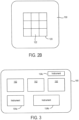
- FIG. 2B illustrates an arrangement of the internal display 120 from a front view relative to the external region 150.
- the internal display 120 has a plurality of variable transparency areas 122.
- FIG. 2B illustrates only nine variable transparency areas 122.
- the number of variable transparency areas 122 may be many more than nine.
- the variable transparency areas 122 are transparent, at least a portion of the external region 150 may be seen on the internal display 120 by the user eye 140. That is, the internal display 120 is arranged to display at least a portion of the external region 150 external to the HWD 100.
- the internal display 120 may include a variable transparency layer 121, which includes the variable transparency areas 122, and a combiner 123.
- the combiner 123 combines an image of the external region 150 which is not blocked by the variable transparency layer 121 with an image provided via the controller 130.
- the transparency layer 121 may be an electrochromic layer, for example, where the transparency of the variable transparency areas 122 are controlled by voltages applied via the controller 130.
- An example of a variable transparency layer and combiner may be found, for example, in U.S. Application No. 15/945,708 entitled "SPATIALLY ADDRESSABLE ELECTROCHROMIC LIGHT MODULATOR" filed April 4, 2018 , which Application issued September 14, 2021 as U.S. Patent 11,119,379 , which is incorporated by reference in its entirety.
- the controller 130 may include a processor 132 and a memory 134.
- the controller 130 controls the eye tracker 170 to determine the orientation and position of the user eye 140, and possibly the head tracker 175 to determine the orientation and position of the user head.
- the controller 130 further controls the internal display 120 to vary the transparency of the variable transparency areas 122. Still further the controller 130 controls the internal display 120 to display overlay information on the internal display 120.
- the controller 130 may control the variable transparency areas 122 to block a view to the user eye of a region of the external region 150, and to control the internal display 120 to overlay information in a region of the internal display 120 corresponding to the region of the external region 150 which is blocked.
- the overlay information may include text and/or symbols, for example.
- FIG. 3 illustrates an example of an external region 150 according to the inventive concepts disclosed herein.
- the external region 150 may be a view within a cockpit of an aircraft, or within a driver's region of a vehicle, for example.
- the external region 150 may include a number of portions.
- the portions may include window portions 152, which provide a view of outside the cockpit, and cockpit instrument sections 154A, 154B and 154C corresponding to flight instruments.
- the cockpit instrument sections may include displays.
- FIG. 4 illustrates an example of the internal display 120 illustrating overlay regions 124, and a non-overlay region 126.
- the overlay region 124 corresponds to regions of the external region 150 which are blocked from view via the variable transparency areas 122.
- the non-overlay region 126 correspond to regions of the external region 150 which are not blocked from view via the variable transparency areas 122, where those unblocked regions of the external region 150 are displayed on the internal display 120.
- the controller 130 controls the internal display 120 to display overlay information at the overlay regions 124.
- FIG. 5 illustrates an example of the internal display 120 according to inventive concepts disclosed herein, where the overlay region 124 corresponds to a checklist.
- the overlay information is information regarding the checklist, such as the items listed in the checklist.
- the overlay region 124 of the internal display 120 may be arranged to occlude a non-critical cockpit instrument section of the external region 150, so as to not block important information.
- the non-critical cockpit instrument section which is blocked may be a flight plan, for example, when the overlay region 124 corresponds to a checklist with a start-up sequence, for example.
- the controller 130 may confirm that a user is looking at the checklist information using the eye tracker 170 and possibly the head tracker 175.
- the eye tracker 170 tracks the user eye 140 orientation and position, and sends the user eye orientation and position data to the controller 130.
- the controller 130 determines whether or not the user eye 140 is looking at the checklist information using the user eye orientation and position data, and using the position of the overlay region 124 corresponding to the checklist.
- FIG. 6 illustrates an example of the internal display 120 according to inventive concepts disclosed herein, where the overlay region 124 corresponds to a display region of the external region 150 where the display region has failed.
- the overlay information is virtual information regarding a replacement display region corresponding to the failed display region.
- the overlay region 124 of the internal display 120 may be arranged to occlude the failed display region of the external region 150.
- a warning signal may be sent to the controller 130.
- the warning signal is received by the controller 130, and indicates that a display region of the external region has failed.
- the controller 130 controls the internal display 120 to overlay the replacement display region over the regions of the internal display 120 corresponding to the display region of the external region which has failed.
- FIG. 7 illustrates an example of the internal display 120 according to inventive concepts disclosed herein, where the overlay region 124 corresponds to emergency information.
- the overlay information is information regarding an emergency.
- the overlay region 124 of the internal display 120 may be arranged to occlude a non-critical cockpit instrument section of the external region 150, so as to not block important information.
- the controller 130 may receive an emergency signal indicating that an emergency has occurred.
- the controller 130 controls the internal display 120 to overlay emergency information indicating an emergency during the time that the emergency continues.
- the controller 130 may confirm that the user is looking at the emergency information using the eye tracker 170, and possibly the head tracker 175.
- the eye tracker 170 tracks the user eye 140 orientation and position, and sends the user eye orientation and position data to the controller 130.
- the controller 130 determines whether or not the user eye 140 is looking at the emergency information using the user eye orientation and position data, and using the position of the overlay region 124 corresponding to the emergency information.
- the controller 130 may electrochromically occlude or partially occlude all non-critical, non-emergency portions of the field of view and emphasize the critical portions.
- FIG. 8 illustrates an example of the internal display 120 according to inventive concepts disclosed herein, where the overlay region 124 corresponds to direction information for a first overlay region 124a and to peripheral information for a second overlay region 124b.
- the first overlay region 124a for the direction information may be disposed in an inner region of the internal display 120, for example.
- the second overlay region 124b for the peripheral information is disposed in a peripheral region of the internal display 120.
- the direction information is information directing a user's attention to the second overlay region 124b. For example, if the second overlay region 124b is in the upper right-hand corner of the internal display 120, the direction information may be an arrow pointing to the second overlay region 124b. As another example, if the second overlay region 124b is in the upper right-hand corner of the internal display 120, the direction information may be text saying "LOOK IN UPPER RIGHT.”
- the controller 130 may confirm that a user is looking at the peripheral information using the eye tracker 170, and possibly the head tracker 175.
- the eye tracker 170 tracks the user eye 140 orientation and position, and sends the user eye orientation and position data to the controller 130.
- the controller 130 determines whether or not the user eye 140 is looking at the peripheral information using the user eye orientation and position data, and using the position of the second overlay region 124b corresponding to the peripheral information.
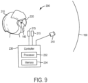
- FIG. 9 is a schematic illustrating a HWD 200 according to inventive concepts disclosed herein.
- the HWD 200 includes a head attachment region 210, an internal display 220, a controller 230 and one or more image detectors 310.
- the HWD may further include an eye tracker 370 and a head tracker 375.
- the head attachment region 210 may be worn by a user, and may be a helmet, for example. Alternatively, the head attachment region 210 may include googles, for example.
- the internal display 220 is attached to the head attachment region 210.
- the HWD 200 including the head attachment region 210, internal display 220, controller 130, and one or more image detectors 310, is shown in FIG. 1 relative to a user eye 140, and an external region 150.
- the user eye 140 and the external region 150 are not part of the HWD 200.
- the eye tracker 370 tracks the position and orientation of the user eye 140.
- the head tracker 375 tracks the position and orientation of the user head.
- the one or more image detectors 310 are arranged to detect an image of the external region 150 external to the internal display 220.
- the one or more image detectors 310 may be cameras, for example. In the case that the one or more image detectors 310 are a plurality of image detectors, the images from the one or more image detectors 310 may be combined to form a combined image.
- the controller 230 may include a processor 232 and a memory 234.
- the controller 230 controls the eye tracker 370 to determine the orientation and position of the user eye 140.
- the eye tracker 370 may include a head tracker tracking the head orientation and position of the user.
- the controller 230 further controls the internal display 220 to display the detected image from the one or image detectors 310, and further to display overlay information over the displayed detected image.
- the overlay information may include text and/or symbols, for example.
- the internal display 220 may be a virtual reality display, or may be an augmented reality display, for example.
- the overlay information may include warning information, emergency information, checklist information, or replacement display information, in a similar fashion to the HWD 100 of FIG. 1 .
- the overlay information may include critical information.
- the eye tracker 370 may be arranged to track a position and orientation of the eye 140 of a user wearing the HWD.
- the head tracker 375 may be arranged to track a position and orientation of the head of a user wearing the HWD.
- the controller 230 may confirm that the user is viewing the critical information based on the tracked eye position and orientation of the user.
- the controller 220 may be configured to provide foveated rendering.
- the controller 220 may be configured to increase a resolution of a region of the internal display 220 viewed by an eye 140 of a user and to decrease a resolution of another region of the internal display not viewed by the user based on the tracked eye position of the user.
- the processing time of the controller may be reduced since the regions of the internal display not viewed are lower resolution and thus the rendering time for the lower resolution regions is reduced.
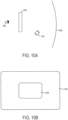
- FIG. 10A illustrates an arrangement of the internal display 220 from a side view relative to the user eye 140, at least one image detector 310, and the external region 150
- FIG. 10B illustrates an arrangement of the internal display 220 from a front view relative to the external region 150.
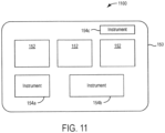
- FIG. 11 illustrates an example of an image 1100 detected by the at least one image detector 310 of an external region 150 according to the inventive concepts disclosed herein.
- the image 1100 of the external region 150 may be a view within a cockpit of an aircraft, or within a driver's region of a vehicle, for example.
- the image of the external region 150 may include a number of portions.
- the portions may include window portions 152, which provide a view of outside the cockpit, and cockpit instrument sections 154A, 154B and 154C corresponding to flight instruments.
- the cockpit instrument sections may include displays.
- the external region 150 may include a region external to the cockpit, which would enclose the HWD 200.
- the display 220 may display only rendered images.
- the internal display 220 displays the image from the at least one image detector 310, and further the controller 230 controls the internal display 220 to display overlay information over the image from the at least one image detector 310.
- the at least one image detector 310 may be arranged to only image an external region separate from the cockpit instrument sections.
- the at least one image detector 310 may be arranged to image regions where the user's hands may be, and regions beyond the cockpit, such as regions seen through the window portions 152, to allow for navigation of the aircraft by a pilot.
- the image information of the instrument sections 154A, 154B and 154C within the cockpit are provided by the controller 230, and are not based on images from the at least one image detector 310.
- the internal display 220 displays an image from the external region 150 as seen by the user eye 140, the image from the at least one image detector 310, and the display overlay information from the controller 230.
- the display 220 may be transparent to allow an image from the external region 150 to be seen by a user eye 140.
- the at least one image detector 310 may be arranged to image an external region within the cockpit as well beyond the cockpit, such as another external region which may overlap the external region.
- Embodiments of the inventive concepts disclosed herein regarding HWDs with variable transparency areas provide for functions such as enhancement, replacement, augmentation and occlusion in displays.
- the HWDs provide functionality for providing check lists at appropriate times, replacing the view of failed displays, providing visual information for emergency situations, and providing peripheral cue augmentation.
- HWDs may also be arranged in a mixed reality configuration where an internal display viewed by a user includes images of a region external to the internal display which is detected by image detectors.
- the internal display displays the detected image along with overlay information.
- Such an arrangement may obtain a wide FOV, such as nearly 120 degrees, for example. Further, real world imagery is relayed to the user via the image detectors.
Landscapes
- Engineering & Computer Science (AREA)
- Physics & Mathematics (AREA)
- General Physics & Mathematics (AREA)
- General Engineering & Computer Science (AREA)
- Theoretical Computer Science (AREA)
- Optics & Photonics (AREA)
- Human Computer Interaction (AREA)
- Computer Graphics (AREA)
- Computer Hardware Design (AREA)
- Software Systems (AREA)
- User Interface Of Digital Computer (AREA)
- Controls And Circuits For Display Device (AREA)
Abstract
Description
- The inventive concepts disclosed herein generally relate to head worn displays.
- Head worn displays (HWDs) may be worn by a user and provide a user with visual information. For virtual reality displays, all of the image on the display viewed by a user may be rendered. Augmented reality displays, on the other hand, combine light by optical means to present a user with virtual information superimposed on the real world.
- Augmented reality HWDs typically compromise between cost, field of view (FOV) and size. Most traditional HWD application for augmented reality include increasing the size of conventional optics to the point they are overly large and cumbersome to the user in order to achieve a wide FOV.
- In one aspect, embodiments of the inventive concepts disclosed herein are directed to a head worn display (HWD) including a head attachment region, an internal display and a controller. The internal display is viewable by a user and includes variable transparency areas. The internal display is arranged to display at least a portion of an external region external to the HWD. The controller is configured to control the variable transparency areas to block view of a region of the external region and to control the internal display to overlay information in a region of the internal display corresponding to the region of the external region which is blocked.
- In a further aspect, embodiments of the inventive concepts disclosed herein are directed to a HWD including a head attachment region, an internal display viewable by a user of the HWD, one or more image detectors, and a controller. The one or more image detectors are arranged to detect an image of an external region external to the internal display. The controller is configured to control the internal display to display the detected image and to overlay information over the displayed detected image.
- Implementations of the inventive concepts disclosed herein may be better understood when consideration is given to the following detailed description thereof. Such description makes reference to the included drawings, which are not necessarily to scale, and in which some features may be exaggerated and some features may be omitted or may be represented schematically in the interest of clarity. Like reference numerals in the drawings may represent and refer to the same or similar element, feature, or function. In the drawings:
-
FIG 1 is a schematic illustrating a head worn display according to inventive concepts disclosed herein. -
FIG. 2A illustrates a side view of an arrangement of an internal display according to inventive concepts disclosed herein. -
FIG. 2B illustrates a front view of an arrangement of an internal display according to inventive concepts disclosed herein. -
FIG. 3 illustrates an example of an external region according to inventive concepts disclosed herein. -
FIG. 4 illustrates an example of the internal display illustrating an overlay region and a non-overlay region according to inventive concepts disclosed herein. -
FIG. 5 illustrates an example of the internal display where the overlay region corresponds to a checklist according to inventive concepts disclosed herein. -
FIG. 6 illustrates an example of the internal display where the overlay region corresponds to a display region of an external region where a display region has failed according to inventive concepts disclosed herein. -
FIG. 7 illustrates an example of the internal display where the overlay region corresponds to emergency information according to the inventive concepts disclosed herein. -
FIG. 8 illustrates an example of the internal display where the overlay region corresponds to direction information for a first overlay region and to peripheral information for a second overlay region according to inventive concepts disclosed herein. -
FIG 9 is a schematic illustrating a head worn display having image detectors according to inventive concepts disclosed herein. -
FIG. 10A illustrates a side view of an arrangement of the internal display ofFIG. 9 according to inventive concepts disclosed herein. -
FIG. 10B illustrates a front view of an arrangement of the internal display ofFIG. 9 according to inventive concepts disclosed herein. -
FIG. 11 illustrates an example of an image detected by at least one image detector of an external region according to inventive concepts disclosed herein. - Embodiments of the inventive concepts disclosed herein regarding HWDs with variable transparency areas provide for functions such as enhancement, replacement, augmentation and occlusion in a display. The HWDs provide functionality for providing check lists at appropriate times, replacing the view of failed displays, providing visual information for emergency situations, and providing peripheral cue augmentation, for example.
- HWDs may also be arranged in a mixed reality configuration where an internal display viewed by a user includes images of a region external to the internal display which is detected by image detectors. In the mixed reality configuration, the internal display displays the detected image along with overlay information. Such an arrangement may obtain a wide FOV, such as nearly 120 degrees, for example. Further, real world imagery is relayed to the user via the image detectors.
-
FIG. 1 is a schematic illustrating aHWD 100 according to inventive concepts disclosed herein. The HWD 100 includes ahead attachment region 110, aninternal display 120, and acontroller 130. The HWD 100 may further include aneye tracker 170 andhead tracker 175. - The
head attachment region 110 may be worn by a user, and may be a helmet, for example. Alternatively, thehead attachment region 110 may include googles, for example. Theinternal display 120 is attached to thehead attachment region 110. - The
HWD 100, including thehead attachment region 110,internal display 120, andcontroller 130, is shown inFIG. 1 relative to auser eye 140, and anexternal region 150. Theuser eye 140 and theexternal region 150 are not part of theHWD 100. Theeye tracker 170 tracks the position and orientation of theuser eye 140. The head tracker 175 tracks the position and orientation of the user head. -
FIG. 2A illustrates an arrangement of theinternal display 120 from a side view relative to theuser eye 140 and theexternal region 150, whileFIG. 2B illustrates an arrangement of theinternal display 120 from a front view relative to theexternal region 150. - The
internal display 120 has a plurality ofvariable transparency areas 122. For ease of illustration,FIG. 2B illustrates only ninevariable transparency areas 122. In general, the number ofvariable transparency areas 122 may be many more than nine. When thevariable transparency areas 122 are transparent, at least a portion of theexternal region 150 may be seen on theinternal display 120 by theuser eye 140. That is, theinternal display 120 is arranged to display at least a portion of theexternal region 150 external to theHWD 100. - As seen in
FIG. 2A , theinternal display 120 may include avariable transparency layer 121, which includes thevariable transparency areas 122, and acombiner 123. Thecombiner 123 combines an image of theexternal region 150 which is not blocked by thevariable transparency layer 121 with an image provided via thecontroller 130. Thetransparency layer 121 may be an electrochromic layer, for example, where the transparency of thevariable transparency areas 122 are controlled by voltages applied via thecontroller 130. An example of a variable transparency layer and combiner may be found, for example, inU.S. Application No. 15/945,708 entitled "SPATIALLY ADDRESSABLE ELECTROCHROMIC LIGHT MODULATOR" filed April 4, 2018 September 14, 2021 as U.S. Patent 11,119,379 - Referring to
FIG. 1 , thecontroller 130 may include aprocessor 132 and amemory 134. Thecontroller 130 controls theeye tracker 170 to determine the orientation and position of theuser eye 140, and possibly thehead tracker 175 to determine the orientation and position of the user head. Thecontroller 130 further controls theinternal display 120 to vary the transparency of thevariable transparency areas 122. Still further thecontroller 130 controls theinternal display 120 to display overlay information on theinternal display 120. - For example, the
controller 130 may control thevariable transparency areas 122 to block a view to the user eye of a region of theexternal region 150, and to control theinternal display 120 to overlay information in a region of theinternal display 120 corresponding to the region of theexternal region 150 which is blocked. The overlay information may include text and/or symbols, for example. -
FIG. 3 illustrates an example of anexternal region 150 according to the inventive concepts disclosed herein. Theexternal region 150 may be a view within a cockpit of an aircraft, or within a driver's region of a vehicle, for example. Theexternal region 150 may include a number of portions. For example, in the case that theexternal region 150 is a view within a cockpit of an aircraft, the portions may includewindow portions 152, which provide a view of outside the cockpit, and cockpit instrument sections 154A, 154B and 154C corresponding to flight instruments. The cockpit instrument sections may include displays. -
FIG. 4 illustrates an example of theinternal display 120 illustratingoverlay regions 124, and anon-overlay region 126. Theoverlay region 124 corresponds to regions of theexternal region 150 which are blocked from view via thevariable transparency areas 122. Thenon-overlay region 126 correspond to regions of theexternal region 150 which are not blocked from view via thevariable transparency areas 122, where those unblocked regions of theexternal region 150 are displayed on theinternal display 120. Thecontroller 130 controls theinternal display 120 to display overlay information at theoverlay regions 124. -
FIG. 5 illustrates an example of theinternal display 120 according to inventive concepts disclosed herein, where theoverlay region 124 corresponds to a checklist. In this case the overlay information is information regarding the checklist, such as the items listed in the checklist. Theoverlay region 124 of theinternal display 120 may be arranged to occlude a non-critical cockpit instrument section of theexternal region 150, so as to not block important information. The non-critical cockpit instrument section which is blocked may be a flight plan, for example, when theoverlay region 124 corresponds to a checklist with a start-up sequence, for example. - The
controller 130 may confirm that a user is looking at the checklist information using theeye tracker 170 and possibly thehead tracker 175. Theeye tracker 170 tracks theuser eye 140 orientation and position, and sends the user eye orientation and position data to thecontroller 130. Thecontroller 130 determines whether or not theuser eye 140 is looking at the checklist information using the user eye orientation and position data, and using the position of theoverlay region 124 corresponding to the checklist. -
FIG. 6 illustrates an example of theinternal display 120 according to inventive concepts disclosed herein, where theoverlay region 124 corresponds to a display region of theexternal region 150 where the display region has failed. In this case the overlay information is virtual information regarding a replacement display region corresponding to the failed display region. Theoverlay region 124 of theinternal display 120 may be arranged to occlude the failed display region of theexternal region 150. - In the case of a failed display region of the
external region 150, a warning signal may be sent to thecontroller 130. The warning signal is received by thecontroller 130, and indicates that a display region of the external region has failed. Thecontroller 130 controls theinternal display 120 to overlay the replacement display region over the regions of theinternal display 120 corresponding to the display region of the external region which has failed. -
FIG. 7 illustrates an example of theinternal display 120 according to inventive concepts disclosed herein, where theoverlay region 124 corresponds to emergency information. In this case the overlay information is information regarding an emergency. Theoverlay region 124 of theinternal display 120 may be arranged to occlude a non-critical cockpit instrument section of theexternal region 150, so as to not block important information. - The
controller 130 may receive an emergency signal indicating that an emergency has occurred. Thecontroller 130 controls theinternal display 120 to overlay emergency information indicating an emergency during the time that the emergency continues. - The
controller 130 may confirm that the user is looking at the emergency information using theeye tracker 170, and possibly thehead tracker 175. Theeye tracker 170 tracks theuser eye 140 orientation and position, and sends the user eye orientation and position data to thecontroller 130. Thecontroller 130 determines whether or not theuser eye 140 is looking at the emergency information using the user eye orientation and position data, and using the position of theoverlay region 124 corresponding to the emergency information. Thecontroller 130 may electrochromically occlude or partially occlude all non-critical, non-emergency portions of the field of view and emphasize the critical portions. -
FIG. 8 illustrates an example of theinternal display 120 according to inventive concepts disclosed herein, where theoverlay region 124 corresponds to direction information for afirst overlay region 124a and to peripheral information for asecond overlay region 124b. Thefirst overlay region 124a for the direction information may be disposed in an inner region of theinternal display 120, for example. Thesecond overlay region 124b for the peripheral information is disposed in a peripheral region of theinternal display 120. The direction information is information directing a user's attention to thesecond overlay region 124b. For example, if thesecond overlay region 124b is in the upper right-hand corner of theinternal display 120, the direction information may be an arrow pointing to thesecond overlay region 124b. As another example, if thesecond overlay region 124b is in the upper right-hand corner of theinternal display 120, the direction information may be text saying "LOOK IN UPPER RIGHT." - The
controller 130 may confirm that a user is looking at the peripheral information using theeye tracker 170, and possibly thehead tracker 175. Theeye tracker 170 tracks theuser eye 140 orientation and position, and sends the user eye orientation and position data to thecontroller 130. Thecontroller 130 determines whether or not theuser eye 140 is looking at the peripheral information using the user eye orientation and position data, and using the position of thesecond overlay region 124b corresponding to the peripheral information. - According to inventive concepts disclosed herein,
FIG. 9 is a schematic illustrating aHWD 200 according to inventive concepts disclosed herein. TheHWD 200 includes ahead attachment region 210, aninternal display 220, acontroller 230 and one ormore image detectors 310. The HWD may further include aneye tracker 370 and ahead tracker 375. - The
head attachment region 210 may be worn by a user, and may be a helmet, for example. Alternatively, thehead attachment region 210 may include googles, for example. Theinternal display 220 is attached to thehead attachment region 210. - The
HWD 200, including thehead attachment region 210,internal display 220,controller 130, and one ormore image detectors 310, is shown inFIG. 1 relative to auser eye 140, and anexternal region 150. Theuser eye 140 and theexternal region 150 are not part of theHWD 200. Theeye tracker 370 tracks the position and orientation of theuser eye 140. Thehead tracker 375 tracks the position and orientation of the user head. - The one or
more image detectors 310 are arranged to detect an image of theexternal region 150 external to theinternal display 220. The one ormore image detectors 310 may be cameras, for example. In the case that the one ormore image detectors 310 are a plurality of image detectors, the images from the one ormore image detectors 310 may be combined to form a combined image. - The
controller 230 may include aprocessor 232 and amemory 234. Thecontroller 230 controls theeye tracker 370 to determine the orientation and position of theuser eye 140. In this regard theeye tracker 370 may include a head tracker tracking the head orientation and position of the user. Thecontroller 230 further controls theinternal display 220 to display the detected image from the one orimage detectors 310, and further to display overlay information over the displayed detected image. The overlay information may include text and/or symbols, for example. Theinternal display 220 may be a virtual reality display, or may be an augmented reality display, for example. - The overlay information may include warning information, emergency information, checklist information, or replacement display information, in a similar fashion to the
HWD 100 ofFIG. 1 . The overlay information may include critical information. Theeye tracker 370 may be arranged to track a position and orientation of theeye 140 of a user wearing the HWD. Thehead tracker 375 may be arranged to track a position and orientation of the head of a user wearing the HWD. Thecontroller 230 may confirm that the user is viewing the critical information based on the tracked eye position and orientation of the user. - The
controller 220 may be configured to provide foveated rendering. In this regard, thecontroller 220 may be configured to increase a resolution of a region of theinternal display 220 viewed by aneye 140 of a user and to decrease a resolution of another region of the internal display not viewed by the user based on the tracked eye position of the user. In this case, the processing time of the controller may be reduced since the regions of the internal display not viewed are lower resolution and thus the rendering time for the lower resolution regions is reduced. -
FIG. 10A illustrates an arrangement of theinternal display 220 from a side view relative to theuser eye 140, at least oneimage detector 310, and theexternal region 150, whileFIG. 10B illustrates an arrangement of theinternal display 220 from a front view relative to theexternal region 150. -
FIG. 11 illustrates an example of animage 1100 detected by the at least oneimage detector 310 of anexternal region 150 according to the inventive concepts disclosed herein. Theimage 1100 of theexternal region 150 may be a view within a cockpit of an aircraft, or within a driver's region of a vehicle, for example. The image of theexternal region 150 may include a number of portions. For example, in the case that theimage 1100 ofexternal region 150 is a view within a cockpit of an aircraft, the portions may includewindow portions 152, which provide a view of outside the cockpit, and cockpit instrument sections 154A, 154B and 154C corresponding to flight instruments. The cockpit instrument sections may include displays. Theexternal region 150 may include a region external to the cockpit, which would enclose theHWD 200. - In the case that the
internal display 220 is a virtual reality display, thedisplay 220 may display only rendered images. In this case theinternal display 220 displays the image from the at least oneimage detector 310, and further thecontroller 230 controls theinternal display 220 to display overlay information over the image from the at least oneimage detector 310. - In some applications, such as within a cockpit of an aircraft where the
internal display 220 is a virtual reality display and only rendered information is displayed on theinternal display 220, the at least oneimage detector 310 may be arranged to only image an external region separate from the cockpit instrument sections. In particular, the at least oneimage detector 310 may be arranged to image regions where the user's hands may be, and regions beyond the cockpit, such as regions seen through thewindow portions 152, to allow for navigation of the aircraft by a pilot. In this case, the image information of the instrument sections 154A, 154B and 154C within the cockpit are provided by thecontroller 230, and are not based on images from the at least oneimage detector 310. - In the case that the
internal display 220 is an augmented reality display, theinternal display 220 displays an image from theexternal region 150 as seen by theuser eye 140, the image from the at least oneimage detector 310, and the display overlay information from thecontroller 230. In this case thedisplay 220 may be transparent to allow an image from theexternal region 150 to be seen by auser eye 140. - In some application, such as within a cockpit of an aircraft where the
internal display 220 is an augmented reality display and theinternal display 220 displays an image from theexternal region 150 as seen by theuser eye 140 through a transparent display, the at least oneimage detector 310 may be arranged to image an external region within the cockpit as well beyond the cockpit, such as another external region which may overlap the external region. - Embodiments of the inventive concepts disclosed herein regarding HWDs with variable transparency areas provide for functions such as enhancement, replacement, augmentation and occlusion in displays. The HWDs provide functionality for providing check lists at appropriate times, replacing the view of failed displays, providing visual information for emergency situations, and providing peripheral cue augmentation.
- HWDs may also be arranged in a mixed reality configuration where an internal display viewed by a user includes images of a region external to the internal display which is detected by image detectors. In the mixed reality configuration, the internal display displays the detected image along with overlay information. Such an arrangement may obtain a wide FOV, such as nearly 120 degrees, for example. Further, real world imagery is relayed to the user via the image detectors.
- The embodiments of the inventive concepts disclosed herein have been described in detail with particular reference to preferred embodiments thereof, but it will be understood by those skilled in the art that variations and modifications can be effected within the spirit and scope of the inventive concepts.
Claims (10)
- A head worn display (200), HWD, comprising:a head attachment region (210);an internal display (220) viewable by a user of the HWD;one or more image detectors (310) arranged to detect an image (1100) of an external region (150) external to the internal display;
anda controller (230) configured to control the internal display to display the detected image and to overlay information over the displayed detected image. - The HWD of claim 1, wherein the internal display is an augmented reality display having a transparent region arranged to provide a view of another external region.
- The HWD of claim 2, wherein the another external region includes a display region of a cockpit enclosing the HWD, and overlaps the external region.
- The HWD of claim 3, wherein the external region includes a region external to the cockpit.
- The HWD of claim 1, wherein the internal display is a virtual reality display.
- The HWD of claim 5, wherein the external region includes a region external to a cockpit enclosing the HWD.
- The HWD of claim 1, wherein the overlay information includes critical information, the HWD further comprising an eye tracker (370) arranged to track a position and orientation of an eye of a user wearing the HWD;
and
wherein the controller is configured to confirm that the user is viewing the critical information based on the tracked eye position of the user. - The HWD of claim 1, wherein the overlay information includes any pertinent or critical information.
- The HWD of claim 1, further comprising:an eye tracker (370) arranged to track an eye position of a user wearing the HWD;wherein the controller is configured to increase a resolution of a region of the internal display viewed by the user and to decrease a resolution of another region of the internal display not viewed by the user based on the tracked eye position of the user.
- The HWD of claim 1, wherein the one or more image detectors include cameras.
Applications Claiming Priority (2)
| Application Number | Priority Date | Filing Date | Title |
|---|---|---|---|
| US16/059,742 US11175504B2 (en) | 2018-08-09 | 2018-08-09 | Mixed reality head worn display |
| EP19000344.2A EP3629131B1 (en) | 2018-08-09 | 2019-07-25 | Mixed reality head worn display |
Related Parent Applications (1)
| Application Number | Title | Priority Date | Filing Date |
|---|---|---|---|
| EP19000344.2A Division EP3629131B1 (en) | 2018-08-09 | 2019-07-25 | Mixed reality head worn display |
Publications (3)
| Publication Number | Publication Date |
|---|---|
| EP4439153A2 true EP4439153A2 (en) | 2024-10-02 |
| EP4439153A3 EP4439153A3 (en) | 2025-01-15 |
| EP4439153B1 EP4439153B1 (en) | 2026-05-13 |
Family
ID=67480078
Family Applications (2)
| Application Number | Title | Priority Date | Filing Date |
|---|---|---|---|
| EP24195425.4A Active EP4439153B1 (en) | 2018-08-09 | 2019-07-25 | Mixed reality head worn display |
| EP19000344.2A Active EP3629131B1 (en) | 2018-08-09 | 2019-07-25 | Mixed reality head worn display |
Family Applications After (1)
| Application Number | Title | Priority Date | Filing Date |
|---|---|---|---|
| EP19000344.2A Active EP3629131B1 (en) | 2018-08-09 | 2019-07-25 | Mixed reality head worn display |
Country Status (2)
| Country | Link |
|---|---|
| US (1) | US11175504B2 (en) |
| EP (2) | EP4439153B1 (en) |
Families Citing this family (3)
| Publication number | Priority date | Publication date | Assignee | Title |
|---|---|---|---|---|
| US11893163B2 (en) * | 2020-12-11 | 2024-02-06 | Dell Products L.P. | Information handling system virtual and physical keyboard position coordination |
| US12038795B2 (en) | 2020-12-11 | 2024-07-16 | Dell Products L.P. | Information handling system visual presentation with audio vector based information |
| US12555486B2 (en) * | 2023-09-27 | 2026-02-17 | Honeywell International Inc. | Augmented reality taxi assistant |
Citations (1)
| Publication number | Priority date | Publication date | Assignee | Title |
|---|---|---|---|---|
| US11937905B2 (en) | 2021-12-30 | 2024-03-26 | Oura Health Oy | Techniques for leveraging data collected by wearable devices and additional devices |
Family Cites Families (13)
| Publication number | Priority date | Publication date | Assignee | Title |
|---|---|---|---|---|
| US6037914A (en) | 1997-08-25 | 2000-03-14 | Hewlett-Packard Company | Method and apparatus for augmented reality using a see-through head-mounted display |
| US5913591A (en) | 1998-01-20 | 1999-06-22 | University Of Washington | Augmented imaging using a silhouette to improve contrast |
| US20100238161A1 (en) * | 2009-03-19 | 2010-09-23 | Kenneth Varga | Computer-aided system for 360º heads up display of safety/mission critical data |
| DE102009028498A1 (en) | 2009-08-13 | 2011-02-17 | Daimler Ag | Projection display device for vehicles, has flat combiner element, where combiner element is arranged between vehicle occupant and disk of vehicle |
| US20160187654A1 (en) * | 2011-02-28 | 2016-06-30 | Microsoft Technology Licensing, Llc | See-through near-eye display glasses with a light transmissive wedge shaped illumination system |
| US9244280B1 (en) | 2014-03-25 | 2016-01-26 | Rockwell Collins, Inc. | Near eye display system and method for display enhancement or redundancy |
| US9811954B2 (en) * | 2014-12-02 | 2017-11-07 | Honeywell International, Inc. | Near-to-eye display systems and methods for verifying aircraft components |
| US20160286210A1 (en) | 2015-03-27 | 2016-09-29 | Osterhout Group, Inc. | See-through computer display systems |
| CN104965338A (en) * | 2015-07-20 | 2015-10-07 | 京东方科技集团股份有限公司 | Display panel and display device |
| US20170154446A1 (en) * | 2015-11-30 | 2017-06-01 | Honeywell International Inc. | Methods and apparatus for providing visual overlay assistance for flight preparation |
| TWI589929B (en) | 2016-01-28 | 2017-07-01 | 中強光電股份有限公司 | Head-mounted display |
| US20170256095A1 (en) | 2016-03-02 | 2017-09-07 | Siemens Medical Solutions Usa, Inc. | Blocking screen in Augmented Reality |
| US9995936B1 (en) * | 2016-04-29 | 2018-06-12 | Lockheed Martin Corporation | Augmented reality systems having a virtual image overlaying an infrared portion of a live scene |
-
2018
- 2018-08-09 US US16/059,742 patent/US11175504B2/en active Active
-
2019
- 2019-07-25 EP EP24195425.4A patent/EP4439153B1/en active Active
- 2019-07-25 EP EP19000344.2A patent/EP3629131B1/en active Active
Patent Citations (1)
| Publication number | Priority date | Publication date | Assignee | Title |
|---|---|---|---|---|
| US11937905B2 (en) | 2021-12-30 | 2024-03-26 | Oura Health Oy | Techniques for leveraging data collected by wearable devices and additional devices |
Also Published As
| Publication number | Publication date |
|---|---|
| EP4439153A3 (en) | 2025-01-15 |
| US20200049993A1 (en) | 2020-02-13 |
| EP3629131B1 (en) | 2024-09-18 |
| EP3629131A2 (en) | 2020-04-01 |
| EP4439153B1 (en) | 2026-05-13 |
| EP3629131A3 (en) | 2020-07-22 |
| US11175504B2 (en) | 2021-11-16 |
Similar Documents
| Publication | Publication Date | Title |
|---|---|---|
| US9791694B1 (en) | Transparent film display system for vehicles | |
| US9244280B1 (en) | Near eye display system and method for display enhancement or redundancy | |
| CN106275467B (en) | System and method for integrating heads-up display and heads-down display | |
| US4994794A (en) | Methods and apparatus for displaying data | |
| US8416152B2 (en) | Method and system for operating a near-to-eye display | |
| US9892489B1 (en) | System for and method of providing a virtual cockpit, control panel, or dashboard using augmented reality | |
| EP4439153B1 (en) | Mixed reality head worn display | |
| US5251333A (en) | Helmet mounted display device | |
| US9244649B2 (en) | Piloting assistance system and an aircraft | |
| US20080012730A1 (en) | Device for generating the standby function in a head-up display | |
| CN107487449B (en) | Display system and method for an aircraft | |
| US10604270B2 (en) | Display system of an aircraft | |
| US20170329132A1 (en) | Improvements in and relating to displays | |
| US20140333510A1 (en) | Omnidirectional hud | |
| EP3719561A1 (en) | Head-up display with high brightness | |
| US10409077B2 (en) | Distributed aperture head up display (HUD) | |
| US9950806B2 (en) | Method for displaying an image of a scene outside of an aircraft in an augmented reality context | |
| US20250111810A1 (en) | Display of augmented reality images using a virtual optical display system | |
| US9720233B2 (en) | Compact proximity display utilizing image transfer | |
| US20220366818A1 (en) | Head-up display with display apparatus | |
| EP2500693B1 (en) | Redundant back projection display system | |
| US9245498B2 (en) | Display system having a semitransparent display device displaying symbols with a contrasted outline | |
| EP4627792A1 (en) | Methods, systems, apparatuses, and devices for facilitating provisioning of a virtual experience via an intensity controllable xr display panel | |
| JP2009251027A (en) | Recurrence projection head-up display | |
| US20200192468A1 (en) | Display system and method for an aircraft |
Legal Events
| Date | Code | Title | Description |
|---|---|---|---|
| PUAI | Public reference made under article 153(3) epc to a published international application that has entered the european phase |
Free format text: ORIGINAL CODE: 0009012 |
|
| STAA | Information on the status of an ep patent application or granted ep patent |
Free format text: STATUS: THE APPLICATION HAS BEEN PUBLISHED |
|
| AC | Divisional application: reference to earlier application |
Ref document number: 3629131 Country of ref document: EP Kind code of ref document: P |
|
| AK | Designated contracting states |
Kind code of ref document: A2 Designated state(s): AL AT BE BG CH CY CZ DE DK EE ES FI FR GB GR HR HU IE IS IT LI LT LU LV MC MK MT NL NO PL PT RO RS SE SI SK SM TR |
|
| RIN1 | Information on inventor provided before grant (corrected) |
Inventor name: KEITH, CHRISTOPHER A. Inventor name: STRATTON, ERIC P. Inventor name: TIANA, CARLO L. |
|
| REG | Reference to a national code |
Free format text: PREVIOUS MAIN CLASS: G02B0027010000 Ref country code: DE Ref legal event code: R079 Ref document number: 602019084938 Country of ref document: DE Free format text: PREVIOUS MAIN CLASS: G02B0027010000 Ipc: G06F0003010000 |
|
| PUAL | Search report despatched |
Free format text: ORIGINAL CODE: 0009013 |
|
| AK | Designated contracting states |
Kind code of ref document: A3 Designated state(s): AL AT BE BG CH CY CZ DE DK EE ES FI FR GB GR HR HU IE IS IT LI LT LU LV MC MK MT NL NO PL PT RO RS SE SI SK SM TR |
|
| RIC1 | Information provided on ipc code assigned before grant |
Ipc: G02B 27/01 20060101ALI20241206BHEP Ipc: G06F 3/01 20060101AFI20241206BHEP |
|
| STAA | Information on the status of an ep patent application or granted ep patent |
Free format text: STATUS: REQUEST FOR EXAMINATION WAS MADE |
|
| 17P | Request for examination filed |
Effective date: 20250715 |
|
| GRAP | Despatch of communication of intention to grant a patent |
Free format text: ORIGINAL CODE: EPIDOSNIGR1 |
|
| STAA | Information on the status of an ep patent application or granted ep patent |
Free format text: STATUS: GRANT OF PATENT IS INTENDED |
|
| INTG | Intention to grant announced |
Effective date: 20260115 |
|
| GRAS | Grant fee paid |
Free format text: ORIGINAL CODE: EPIDOSNIGR3 |
|
| GRAA | (expected) grant |
Free format text: ORIGINAL CODE: 0009210 |
|
| STAA | Information on the status of an ep patent application or granted ep patent |
Free format text: STATUS: THE PATENT HAS BEEN GRANTED |
|
| AC | Divisional application: reference to earlier application |
Ref document number: 3629131 Country of ref document: EP Kind code of ref document: P |
|
| AK | Designated contracting states |
Kind code of ref document: B1 Designated state(s): AL AT BE BG CH CY CZ DE DK EE ES FI FR GB GR HR HU IE IS IT LI LT LU LV MC MK MT NL NO PL PT RO RS SE SI SK SM TR |
|
| REG | Reference to a national code |
Ref country code: CH Ref legal event code: F10 Free format text: ST27 STATUS EVENT CODE: U-0-0-F10-F00 (AS PROVIDED BY THE NATIONAL OFFICE) Effective date: 20260513 |