EP4439079A1 - Automatic wire connection apparatus for circuit board testing - Google Patents
Automatic wire connection apparatus for circuit board testing Download PDFInfo
- Publication number
- EP4439079A1 EP4439079A1 EP24152130.1A EP24152130A EP4439079A1 EP 4439079 A1 EP4439079 A1 EP 4439079A1 EP 24152130 A EP24152130 A EP 24152130A EP 4439079 A1 EP4439079 A1 EP 4439079A1
- Authority
- EP
- European Patent Office
- Prior art keywords
- circuit board
- probe
- wire connection
- connection apparatus
- wire
- Prior art date
- Legal status (The legal status is an assumption and is not a legal conclusion. Google has not performed a legal analysis and makes no representation as to the accuracy of the status listed.)
- Pending
Links
Images


Classifications
-
- G—PHYSICS
- G01—MEASURING; TESTING
- G01R—MEASURING ELECTRIC VARIABLES; MEASURING MAGNETIC VARIABLES
- G01R31/00—Arrangements for testing electric properties; Arrangements for locating electric faults; Arrangements for electrical testing characterised by what is being tested not provided for elsewhere
- G01R31/28—Testing of electronic circuits, e.g. by signal tracer
- G01R31/2801—Testing of printed circuits, backplanes, motherboards, hybrid circuits or carriers for multichip packages [MCP]
- G01R31/2806—Apparatus therefor, e.g. test stations, drivers, analysers, conveyors
- G01R31/2808—Holding, conveying or contacting devices, e.g. test adapters, edge connectors, extender boards
-
- G—PHYSICS
- G01—MEASURING; TESTING
- G01R—MEASURING ELECTRIC VARIABLES; MEASURING MAGNETIC VARIABLES
- G01R1/00—Details of instruments or arrangements of the types included in groups G01R5/00 - G01R13/00 and G01R31/00
- G01R1/02—General constructional details
- G01R1/06—Measuring leads; Measuring probes
- G01R1/067—Measuring probes
- G01R1/06711—Probe needles; Cantilever beams; "Bump" contacts; Replaceable probe pins
- G01R1/06716—Elastic
- G01R1/06722—Spring-loaded
Definitions
- One or more embodiments relate to an automatic wire connection apparatus for circuit board testing.
- test points in the BMS circuit board are soldered to wires and thus connected to an automatic verification apparatus.
- the number of test points is usually large, e.g., more than tens of points.
- an apparatus for connecting a wire for circuit board testing to a circuit board and a circuit board verification apparatus includes a probe configured to electrically connect a test point included in the circuit board to a wire for circuit board testing by soldering the wire to the test point, and a robot arm configured to place the probe at a preset position on the circuit board.
- the probe may be further configured to shorten and lengthen in a major axis direction.
- the probe includes a built-in elastic spring.
- the probe may be further configured to shorten while being moved by the robot arm, and lengthen when placed at the preset position on the circuit board.
- the probe may be fixed between the circuit board and a fixing board by lengthening when placed at the preset position on the circuit board.
- the term “and/or” includes any and all combinations of one or more of the associated listed items. Further, terms such as “first,” “second,” etc., are used only to distinguish one component from another, and such components must not be limited by these terms. In addition, a singular expression also includes the plural meaning as long as it is not inconsistent with the context. In addition, the terms “comprises,” “includes,” “has”, and the like used herein specify the presence of stated features or components, but do not preclude the presence or addition of one or more other features or components.
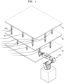
- FIG. 1 is a diagram for describing a configuration and an operation of a wire connection apparatus according to an embodiment.
- the wire connection apparatus may be an apparatus for connecting a wire for circuit board testing to a circuit board 30 and a circuit board verification apparatus.
- the verification apparatus is not depicted in Figure 1 and may for example be an apparatus configured to test, or otherwise verify the functionality of, the circuit board 30.
- the wire connection apparatus may include a probe 200 and a robot arm 100.
- the probe 200 may electrically connect a test point 40 included in the circuit board 30 to a wire for circuit board testing by soldering them (i.e. by soldering the wire to the test point).
- a plurality of test points 40 may be provided.
- the probe 200 may be electrically connected to a wire for circuit board testing.
- a plurality of probes 200 according to an embodiment may be used to electrically connect the plurality of test points 40 to the circuit board verification apparatus.
- the robot arm 100 may place the probe 200 at a preset position on the circuit board 30.
- the preset position may be a test point 40.
- the robot arm 100 according to an embodiment may place the plurality of probes 200 respectively at preset positions of the plurality of test points 40 on the circuit board 30.
- the robot arm 100 may perform an operation of holding the probe 200, an operation of moving the probe 200, an operation of releasing the probe 200, and the like.
- the robot arm 100 may place the probe 200 connected to the wire on designated coordinates.
- the probe 200 may include a built-in (i.e. included within the probe 200) elastic member, such as a spring, and thus may vertically (e.g., along its lengthwise direction) stretch to be fixed between the circuit board 30 and an upper fixing board 10 or a lower fixing board 20.
- a built-in (i.e. included within the probe 200) elastic member such as a spring
- vertically e.g., along its lengthwise direction
- directional terms such as “vertical” may be understood as referring to directions relative to the apparatus as depicted in the figures, and not as implying any particular orientation of the apparatus itself.
- the probe may thus be able to shorten and lengthen, and thereby be considered an elastic probe. For example, as illustrated in FIG.
- the probe 200 may be positioned to extend, e.g., lengthwise, in a vertical direction (e.g., a direction normal to a major surface of the circuit board 30) between the circuit board 30 and an upper fixing board 10 or a lower fixing board 20.
- a vertical direction e.g., a direction normal to a major surface of the circuit board 30
- the wire connection apparatus may include the upper fixing board 10 and the lower fixing board 20 that serve to fix the probe 200 on and under the circuit board 30.
- the circuit board 30 may be arranged between the upper fixing board 10 and the lower fixing board 20 in the vertical direction, e.g., each of the upper fixing board 10 and the lower fixing board 20 may completely overlap the circuit board 30 in the vertical direction.
- the wire connection apparatus may include the robot arm 100 that moves the vertically stretchable (i.e. elastic) probe 200 in X-, Y-, and Z-axis directions on the circuit board 30.
- the probe 200 of the wire connection apparatus may be locked when pressed up and down (i.e. retracted) in the major axis direction, and thus, may vertically shorten to be movable.
- the probe 200 may be unlocked, and thus, may vertically lengthen to be fixed between the circuit board 30 and the upper fixing board 10 or the lower fixing board 20.
- the wire connection apparatus may include a memory, a processor, and a communication module. However, the disclosure is not limited thereto, and the wire connection apparatus may further include other components or may omit some components. Some components of the wire connection apparatus may be separated into a plurality of apparatuses, or a plurality of components of the wire connection apparatus may be integrated into one apparatus.
- the memory is a computer-readable recording medium and may include a permanent mass storage device, e.g., random-access memory (RAM), read-only memory (ROM), or a disk drive.
- a permanent mass storage device e.g., random-access memory (RAM), read-only memory (ROM), or a disk drive.
- the memory may temporarily or permanently store program code for controlling the wire connection apparatus.
- the processor controls the overall operation of the wire connection apparatus.
- the processor may be implemented in a form that selectively includes a processor known in the art, an application-specific integrated circuit (ASIC), other chipsets, a logic circuit, a register, a communication modem, and/or a data processing device, in order to perform the above-described operation.
- ASIC application-specific integrated circuit
- the processor may perform basic arithmetic, logic, and input/output operations, and may execute, e.g., program code stored in the memory.
- the processor may store data in the memory or load data stored in the memory.
- the processor may control an operation of the robot arm 100.
- the processor may use the robot arm 100 to move the probe 200 to a preset (e.g., pre-stored or predetermined) position of the test point 40 of the circuit board 30, based on the preset (e.g., pre-stored) position of the test point 40.
- a preset e.g., pre-stored or predetermined
- the communication module may provide a function for communicating with an external server through a network. For example, a request generated by the processor of the wire connection apparatus according to program code stored in a recording device, e.g., a memory, may be transmitted to the external server through the network under control of the communication module. Conversely, a control signal or command, content, a file, and the like provided under control of a processor of the external device may be received by the wire connection apparatus through the communication module via the network. For example, a control signal or command received from the external server through the communication module may be delivered to the processor or the memory.
- the communication method is not limited, and may include short-range wireless communication between devices, as well as a communication method utilizing a communication network that may include, e.g., a mobile communication network, wired Internet, wireless Internet, or a broadcasting network.
- the network may include any one or more of a personal area network (PAN), a local area network (LAN), a campus area network (CAN), a metropolitan area network (MAN), a wide area network (WAN), a broadband network (BBN), an Internet network, and the like.
- PAN personal area network
- LAN local area network
- CAN campus area network
- MAN metropolitan area network
- WAN wide area network
- BBN broadband network
- Internet network and the like.
- the network may include any one or more of network topologies including, e.g., a bus network, a star network, a ring network, a mesh network, a star-bus network, a tree or hierarchical network, and the like.
- network topologies including, e.g., a bus network, a star network, a ring network, a mesh network, a star-bus network, a tree or hierarchical network, and the like.
- the wire connection apparatus may include an input/output interface.
- the input/output interface may be a unit for interfacing with an input device and an output device.
- the input device may include e.g., a keyboard or mouse
- the output device may include, e.g., a display for displaying a communication session of an application.
- the input/output interface may be a unit for interfacing with a device in which functions for input and output are integrated, e.g., a touch screen.
- the processor of the wire connection apparatus may display a service screen or content configured by using data provided by an external server, on a display through the input/output interface.
- the wire connection apparatus may include more components than those illustrated in FIG. 1 .
- the wire connection apparatus may be implemented to include at least some of the above-described input/output devices, or may further include other components, e.g., a battery that supplies power to internal components, a charging device, various sensors, a database, and the like.
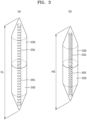
- FIGS. 2 and 3 are diagrams for describing the probe 200 according to an embodiment.
- the probe 200 may be configured to shorten and lengthen in its major axis direction, e.g., in its lengthwise direction.
- the probe 200 may include a built-in elastic spring (or other compressibly elastic member).
- the probe 200 may include an upper probe part 230 and a lower probe part 250.
- the upper probe part 230 may include an upper spring 235
- the lower probe part 250 may include a lower spring 255.
- the probe 200 may include any suitable number of parts and springs, e.g., one or more springs.
- each of the upper and lower probe parts 230 and 250 may include a flat end and a connection end (e.g., a sharp end) opposite the flat end, such that the connection end may be connected to the circuit board 30, the upper fixing board 10, or the lower fixing board 20.
- the flat ends of the upper and lower probe parts 230 and 250 may be connected to each other, such that opposite ends of the combined structure of the upper and lower probe parts 230 and 250 (i.e., the probe 200) may be sharp and point away from each other.
- the upper and lower springs 235 and 255 may be coaxial (e.g., vertically aligned) and may be positioned along the longitudinal directions of the upper and lower probe parts 230 and 250, respectively.
- the combined structure of the upper and lower springs 235 and 255 may extend through a center of the probe 200 (e.g., along its longitudinal direction), thereby imparting flexibility and elasticity to the probe 200 and facilitating shortening and lengthening of the probe 200- along its longitudinal direction.
- the probe 200 may shorten and lengthen in the major axis direction.
- the probe 200 may lengthen in the major axis direction to have a major axis length or a major axis height of a maximum length HL.
- the probe 200 may shorten in the major axis direction to have a major axis length or a major axis height of a minimum length HS.
- the probe 200 may be configured to shorten while being moved by the robot arm 100, and lengthen when placed at a preset position on the circuit board 30 (i.e. the robot arm may cause the probe to lengthen in response to being placed at the previous position). For example, while being moved by the robot arm 100, the probe 200 may shorten to the minimum length HS to be movable. In addition, when placed at the test point 40 on the circuit board 30, the probe 200 may lengthen to the maximum length HL. The shortening and lengthening may be performed by action of the robot arm 100.
- FIG. 4 is a diagram for describing an operation of a wire connection apparatus according to an embodiment.
- the probe 200 may be placed at a preset position on the circuit board 30, and then lengthen to be fixed between the circuit board 30 and the upper fixing board 10.
- the probe 200 may be placed at the position of the test point 40 on the circuit board 30 and then lengthen to the maximum length HL.
- the probe 200 may be fixed between the circuit board 30 and the upper fixing board 10 or the lower fixing board 20.
- a length h of a space between the upper fixing board 10 and the circuit board 30, or a length h of a space between the lower fixing board 20 and the circuit board 30 may be equal to the length of the major axis of the probe 200 having lengthened to the maximum length HL, e.g., lengthening and shortening of the probe 200 may be controlled and adjusted via a controller in accordance with its contact with the robot arm 100 or the test point 40 on the circuit board 30.
- wiring work for connecting a test point of a circuit board to an automatic inspection apparatus may be automatically performed in a manner in which a robot arm places an elastic probe at a desired position.
- the robot arm may automatically place each of a plurality of elastic probes at a corresponding one of a plurality of test points.
- This may be "automatic" in the sense that the placing of the probe or probes may be performed according to a preset plan without direct user control during the placing of the probe or probes.
- the apparatus and/or system described above may be implemented as a hardware component, a software component, and/or a combination of a hardware component and a software component.
- the apparatus and components described in the embodiments may be implemented by using one or more general-purpose computers or special-purpose computers, e.g., a processor, a controller, an arithmetic logic unit (ALU), a digital signal processor, a microcomputer, a field-programmable gate array (FPGA), a programmable logic unit (PLU), a microprocessor, or any other device configured to execute and respond to instructions.
- the processor may execute an operating system (OS) and one or more software applications running on the OS.
- the processor may also access, store, modify, process, and generate data in response to execution of software.
- OS operating system
- the processor may also access, store, modify, process, and generate data in response to execution of software.
- processors may include a plurality of processing elements and/or a plurality of types of processing elements.
- the processor may include one or more processors and one controller.
- other processing configurations are also possible, e.g., a parallel processor.
- the software may include a computer program, code, instructions, or a combination of one or more thereof, and may configure the processor to operate as desired or may independently or collectively instruct the processor.
- Software and/or data may be embodied permanently or temporarily in any type of machine, component, physical or virtual equipment, computer storage medium or device, or in a propagated signal wave capable of providing instructions or data to or being interpreted by the processor.
- the software may be distributed on networked computer systems and stored or executed in a distributed manner.
- the software and data may be stored in one or more computer-readable recording media.
- the method according to an embodiment may be embodied as program commands executable by various computer devices, and recorded on a computer-readable medium.
- the computer-readable medium may include program instructions, data files, data structures, or the like separately or in combinations.
- the program commands to be recorded on the medium may be specifically designed and configured for an embodiment, or may be well-known to and be usable by those skilled in the art of computer software.
- Examples of the computer-readable recording medium may include magnetic media, e.g., hard disks, floppy disks, or magnetic tapes, optical media, e.g., a compact disc ROM (CD-ROM) or a digital video disc (DVD), magneto-optical media, e.g., a floptical, and hardware devices, e.g., ROM, RAM, or flash memory, which are specially configured to store and execute program instructions.
- Examples of the program instructions include not only machine code, e.g., code made by a compiler, but also high-level language code that is executable by a computer by using an interpreter or the like.
- the hardware device may be configured to operate as one or more software modules to perform an operation of an embodiment, and vice versa.
- test points in the BMS circuit board are soldered to wires manually, thereby requiring a lot of time and effort from a worker.
- one or more embodiments of the present disclosure include an automatic wire connection apparatus for circuit board testing.
Landscapes
- Physics & Mathematics (AREA)
- General Physics & Mathematics (AREA)
- Engineering & Computer Science (AREA)
- Computer Hardware Design (AREA)
- Microelectronics & Electronic Packaging (AREA)
- General Engineering & Computer Science (AREA)
- Measuring Leads Or Probes (AREA)
- Tests Of Electronic Circuits (AREA)
Abstract
Provided is an apparatus for connecting a wire for circuit board testing to a circuit board (30) and a circuit board verification apparatus, the apparatus including a probe (200) configured to electrically connect a test point (40) included in the circuit board (30) to a wire for circuit board testing by soldering the wire to the test point (40), and a robot arm (100) configured to place the probe (200) at a preset position on the circuit board (30).
Description
- One or more embodiments relate to an automatic wire connection apparatus for circuit board testing.
- In firmware (FW) verification of a battery management system (BMS) circuit board, numerous test points in the BMS circuit board are soldered to wires and thus connected to an automatic verification apparatus. The number of test points is usually large, e.g., more than tens of points.
- According to one or more embodiments, an apparatus for connecting a wire for circuit board testing to a circuit board and a circuit board verification apparatus includes a probe configured to electrically connect a test point included in the circuit board to a wire for circuit board testing by soldering the wire to the test point, and a robot arm configured to place the probe at a preset position on the circuit board.
- The probe may be further configured to shorten and lengthen in a major axis direction.
- The probe includes a built-in elastic spring.
- The probe may be further configured to shorten while being moved by the robot arm, and lengthen when placed at the preset position on the circuit board.
- The probe may be fixed between the circuit board and a fixing board by lengthening when placed at the preset position on the circuit board.
- At least some of the above and other features of the invention are set out in the claims.
- Features will become apparent to those of skill in the art by describing in detail example embodiments with reference to the attached drawings, in which:
-
FIG. 1 is a diagram for describing a configuration and an operation of a wire connection apparatus according to an embodiment; -
FIGS. 2 and3 are diagrams for describing a probe according to an embodiment; and -
FIG. 4 is a diagram for describing an operation of a wire connection apparatus according to an embodiment. - Example embodiments will now be described more fully hereinafter with reference to the accompanying drawings; however, they may be embodied in different forms and should not be construed as limited to the embodiments set forth herein. Rather, these embodiments are provided so that this disclosure will be thorough and complete, and will fully convey example implementations to those skilled in the art.
- In the drawing figures, the dimensions of layers and regions may be exaggerated for clarity of illustration. It will also be understood that when a layer or element is referred to as being "on" another layer or substrate, it can be directly on the other layer or substrate, or intervening layers may also be present. In addition, it will also be understood that when a layer is referred to as being "between" two layers, it can be the only layer between the two layers, or one or more intervening layers may also be present. Like reference numerals refer to like elements throughout.
- As used herein, the term "and/or" includes any and all combinations of one or more of the associated listed items. Further, terms such as "first," "second," etc., are used only to distinguish one component from another, and such components must not be limited by these terms. In addition, a singular expression also includes the plural meaning as long as it is not inconsistent with the context. In addition, the terms "comprises," "includes," "has", and the like used herein specify the presence of stated features or components, but do not preclude the presence or addition of one or more other features or components.
- Hereinafter, various embodiments will be described in detail with reference to the accompanying drawings such that those of skill in the art may easily practice the disclosure.
-
FIG. 1 is a diagram for describing a configuration and an operation of a wire connection apparatus according to an embodiment. The wire connection apparatus according to an embodiment may be an apparatus for connecting a wire for circuit board testing to acircuit board 30 and a circuit board verification apparatus. The verification apparatus is not depicted inFigure 1 and may for example be an apparatus configured to test, or otherwise verify the functionality of, thecircuit board 30. - Referring to
FIG. 1 , the wire connection apparatus according to an embodiment may include aprobe 200 and arobot arm 100. - The
probe 200 may electrically connect atest point 40 included in thecircuit board 30 to a wire for circuit board testing by soldering them (i.e. by soldering the wire to the test point). For example, a plurality oftest points 40 may be provided. In addition, theprobe 200 may be electrically connected to a wire for circuit board testing. For example, as illustrated inFIG. 1 , a plurality ofprobes 200 according to an embodiment may be used to electrically connect the plurality oftest points 40 to the circuit board verification apparatus. - The
robot arm 100 may place theprobe 200 at a preset position on thecircuit board 30. The preset position may be atest point 40. For example, as illustrated inFIG. 1 , therobot arm 100 according to an embodiment may place the plurality ofprobes 200 respectively at preset positions of the plurality oftest points 40 on thecircuit board 30. For example, therobot arm 100 may perform an operation of holding theprobe 200, an operation of moving theprobe 200, an operation of releasing theprobe 200, and the like. - In the wire connection apparatus according to an embodiment, the
robot arm 100 may place theprobe 200 connected to the wire on designated coordinates. In addition, theprobe 200 may include a built-in (i.e. included within the probe 200) elastic member, such as a spring, and thus may vertically (e.g., along its lengthwise direction) stretch to be fixed between thecircuit board 30 and anupper fixing board 10 or alower fixing board 20. In the present disclosure, directional terms such as "vertical" may be understood as referring to directions relative to the apparatus as depicted in the figures, and not as implying any particular orientation of the apparatus itself. The probe may thus be able to shorten and lengthen, and thereby be considered an elastic probe. For example, as illustrated inFIG. 1 , theprobe 200 may be positioned to extend, e.g., lengthwise, in a vertical direction (e.g., a direction normal to a major surface of the circuit board 30) between thecircuit board 30 and anupper fixing board 10 or alower fixing board 20. - The wire connection apparatus according to an embodiment may include the
upper fixing board 10 and thelower fixing board 20 that serve to fix theprobe 200 on and under thecircuit board 30. For example, thecircuit board 30 may be arranged between theupper fixing board 10 and thelower fixing board 20 in the vertical direction, e.g., each of theupper fixing board 10 and thelower fixing board 20 may completely overlap thecircuit board 30 in the vertical direction. - The wire connection apparatus according to an embodiment may include the
robot arm 100 that moves the vertically stretchable (i.e. elastic)probe 200 in X-, Y-, and Z-axis directions on thecircuit board 30. Theprobe 200 of the wire connection apparatus according to an embodiment may be locked when pressed up and down (i.e. retracted) in the major axis direction, and thus, may vertically shorten to be movable. In addition, when therobot arm 100 releases theprobe 200, theprobe 200 may be unlocked, and thus, may vertically lengthen to be fixed between thecircuit board 30 and theupper fixing board 10 or thelower fixing board 20. - The wire connection apparatus according to an embodiment may include a memory, a processor, and a communication module. However, the disclosure is not limited thereto, and the wire connection apparatus may further include other components or may omit some components. Some components of the wire connection apparatus may be separated into a plurality of apparatuses, or a plurality of components of the wire connection apparatus may be integrated into one apparatus.
- The memory is a computer-readable recording medium and may include a permanent mass storage device, e.g.,, random-access memory (RAM), read-only memory (ROM), or a disk drive. In addition, the memory may temporarily or permanently store program code for controlling the wire connection apparatus.
- The processor controls the overall operation of the wire connection apparatus. For example, the processor may be implemented in a form that selectively includes a processor known in the art, an application-specific integrated circuit (ASIC), other chipsets, a logic circuit, a register, a communication modem, and/or a data processing device, in order to perform the above-described operation. For example, the processor may perform basic arithmetic, logic, and input/output operations, and may execute, e.g., program code stored in the memory. The processor may store data in the memory or load data stored in the memory.
- The processor may control an operation of the
robot arm 100. For example, the processor may use therobot arm 100 to move theprobe 200 to a preset (e.g., pre-stored or predetermined) position of thetest point 40 of thecircuit board 30, based on the preset (e.g., pre-stored) position of thetest point 40. - The communication module may provide a function for communicating with an external server through a network. For example, a request generated by the processor of the wire connection apparatus according to program code stored in a recording device, e.g., a memory, may be transmitted to the external server through the network under control of the communication module. Conversely, a control signal or command, content, a file, and the like provided under control of a processor of the external device may be received by the wire connection apparatus through the communication module via the network. For example, a control signal or command received from the external server through the communication module may be delivered to the processor or the memory.
- The communication method is not limited, and may include short-range wireless communication between devices, as well as a communication method utilizing a communication network that may include, e.g., a mobile communication network, wired Internet, wireless Internet, or a broadcasting network. For example, the network may include any one or more of a personal area network (PAN), a local area network (LAN), a campus area network (CAN), a metropolitan area network (MAN), a wide area network (WAN), a broadband network (BBN), an Internet network, and the like. In addition, the network may include any one or more of network topologies including, e.g., a bus network, a star network, a ring network, a mesh network, a star-bus network, a tree or hierarchical network, and the like.
- In addition, the wire connection apparatus according to the disclosure may include an input/output interface. The input/output interface may be a unit for interfacing with an input device and an output device. For example, the input device may include e.g., a keyboard or mouse, and the output device may include, e.g., a display for displaying a communication session of an application. As another example, the input/output interface may be a unit for interfacing with a device in which functions for input and output are integrated, e.g., a touch screen. As a more specific example, in processing a command of a computer program loaded into the memory, the processor of the wire connection apparatus may display a service screen or content configured by using data provided by an external server, on a display through the input/output interface.
- In addition, in some embodiments, the wire connection apparatus may include more components than those illustrated in
FIG. 1 . For example, the wire connection apparatus may be implemented to include at least some of the above-described input/output devices, or may further include other components, e.g., a battery that supplies power to internal components, a charging device, various sensors, a database, and the like. -
FIGS. 2 and3 are diagrams for describing theprobe 200 according to an embodiment. - Referring to
FIGS. 2 and3 , theprobe 200 according to an embodiment may be configured to shorten and lengthen in its major axis direction, e.g., in its lengthwise direction. In addition, theprobe 200 according to an embodiment may include a built-in elastic spring (or other compressibly elastic member). For example, as illustrated inFIG. 2 , theprobe 200 may include anupper probe part 230 and alower probe part 250. In addition, theupper probe part 230 may include anupper spring 235, and thelower probe part 250 may include alower spring 255. However, theprobe 200 may include any suitable number of parts and springs, e.g., one or more springs. - For example, as illustrated in
FIG. 2 , each of the upper andlower probe parts circuit board 30, the upper fixingboard 10, or the lower fixingboard 20. For example, the flat ends of the upper andlower probe parts lower probe parts 230 and 250 (i.e., the probe 200) may be sharp and point away from each other. For example, the upper andlower springs lower probe parts lower springs probe 200 and facilitating shortening and lengthening of the probe 200- along its longitudinal direction. - The
probe 200 may shorten and lengthen in the major axis direction. For example, as illustrated in (a) ofFIG. 3 , theprobe 200 may lengthen in the major axis direction to have a major axis length or a major axis height of a maximum length HL. For example, as illustrated in (b) ofFIG. 3 , theprobe 200 may shorten in the major axis direction to have a major axis length or a major axis height of a minimum length HS. - The
probe 200 according to an embodiment may be configured to shorten while being moved by therobot arm 100, and lengthen when placed at a preset position on the circuit board 30 (i.e. the robot arm may cause the probe to lengthen in response to being placed at the previous position). For example, while being moved by therobot arm 100, theprobe 200 may shorten to the minimum length HS to be movable. In addition, when placed at thetest point 40 on thecircuit board 30, theprobe 200 may lengthen to the maximum length HL. The shortening and lengthening may be performed by action of therobot arm 100. -
FIG. 4 is a diagram for describing an operation of a wire connection apparatus according to an embodiment. - Referring to
FIG. 4 , theprobe 200 according to an embodiment may be placed at a preset position on thecircuit board 30, and then lengthen to be fixed between thecircuit board 30 and the upper fixingboard 10. For example, theprobe 200 may be placed at the position of thetest point 40 on thecircuit board 30 and then lengthen to the maximum length HL. In this case, theprobe 200 may be fixed between thecircuit board 30 and the upper fixingboard 10 or the lower fixingboard 20. - For example, as illustrated in
FIG. 4 , a length h of a space between the upper fixingboard 10 and thecircuit board 30, or a length h of a space between the lower fixingboard 20 and thecircuit board 30 may be equal to the length of the major axis of theprobe 200 having lengthened to the maximum length HL, e.g., lengthening and shortening of theprobe 200 may be controlled and adjusted via a controller in accordance with its contact with therobot arm 100 or thetest point 40 on thecircuit board 30. - According to the disclosure, wiring work for connecting a test point of a circuit board to an automatic inspection apparatus, which is performed through manual soldering in the art, may be automatically performed in a manner in which a robot arm places an elastic probe at a desired position. For example, the robot arm may automatically place each of a plurality of elastic probes at a corresponding one of a plurality of test points. This may be "automatic" in the sense that the placing of the probe or probes may be performed according to a preset plan without direct user control during the placing of the probe or probes.
Method Traditional manual soldering Automated method according to Example Embodiments Required time 8 hours or longer 30 minutes or shorter Required number of workers 1 0 - The apparatus and/or system described above may be implemented as a hardware component, a software component, and/or a combination of a hardware component and a software component. The apparatus and components described in the embodiments may be implemented by using one or more general-purpose computers or special-purpose computers, e.g., a processor, a controller, an arithmetic logic unit (ALU), a digital signal processor, a microcomputer, a field-programmable gate array (FPGA), a programmable logic unit (PLU), a microprocessor, or any other device configured to execute and respond to instructions. The processor may execute an operating system (OS) and one or more software applications running on the OS. The processor may also access, store, modify, process, and generate data in response to execution of software. Although some embodiments are described, for convenience of understanding, with reference to examples in which a single processor is used, those of skill in the art would understand that a processor may include a plurality of processing elements and/or a plurality of types of processing elements. For example, the processor may include one or more processors and one controller. In addition, other processing configurations are also possible, e.g., a parallel processor.
- The software may include a computer program, code, instructions, or a combination of one or more thereof, and may configure the processor to operate as desired or may independently or collectively instruct the processor. Software and/or data may be embodied permanently or temporarily in any type of machine, component, physical or virtual equipment, computer storage medium or device, or in a propagated signal wave capable of providing instructions or data to or being interpreted by the processor. The software may be distributed on networked computer systems and stored or executed in a distributed manner. The software and data may be stored in one or more computer-readable recording media.
- The method according to an embodiment may be embodied as program commands executable by various computer devices, and recorded on a computer-readable medium. The computer-readable medium may include program instructions, data files, data structures, or the like separately or in combinations. The program commands to be recorded on the medium may be specifically designed and configured for an embodiment, or may be well-known to and be usable by those skilled in the art of computer software. Examples of the computer-readable recording medium may include magnetic media, e.g., hard disks, floppy disks, or magnetic tapes, optical media, e.g., a compact disc ROM (CD-ROM) or a digital video disc (DVD), magneto-optical media, e.g., a floptical, and hardware devices, e.g., ROM, RAM, or flash memory, which are specially configured to store and execute program instructions. Examples of the program instructions include not only machine code, e.g., code made by a compiler, but also high-level language code that is executable by a computer by using an interpreter or the like. The hardware device may be configured to operate as one or more software modules to perform an operation of an embodiment, and vice versa.
- Although the embodiments have been described with the limited embodiments and the drawings, various modifications and changes may be made by those of skill in the art from the above description. For example, the described techniques may be performed in a different order from the described method, and/or components of the described system, structure, device, circuit, etc. may be combined or integrated in a different form from the described method, or may be replaced or substituted by other components or equivalents to achieve appropriate results.
- By way of summation and review, in comparative examples test points in the BMS circuit board are soldered to wires manually, thereby requiring a lot of time and effort from a worker. In contrast, one or more embodiments of the present disclosure include an automatic wire connection apparatus for circuit board testing.
- Example embodiments have been disclosed herein, and although specific terms are employed, they are used and are to be interpreted in a generic and descriptive sense only and not for purpose of limitation. In some instances, as would be apparent to one of ordinary skill in the art as of the filing of the present application, features, characteristics, and/or elements described in connection with a particular embodiment may be used singly or in combination with features, characteristics, and/or elements described in connection with other embodiments unless otherwise specifically indicated. Accordingly, it will be understood by those of skill in the art that various changes in form and details may be made without departing from the scope of the present invention as set forth in the following claims.
Claims (5)
- An apparatus for connecting a wire for circuit board testing to a circuit board and a circuit board verification apparatus, the apparatus comprising:a probe configured to electrically connect a test point included in the circuit board to the wire for circuit board testing by soldering the wire to the test point; anda robot arm configured to place the probe at a preset position on the circuit board.
- The apparatus as claimed in claim 1, wherein the probe is an elastic probe configured to shorten and lengthen in its major axis direction.
- The apparatus as claimed in claim 2, wherein the probe includes a built-in elastic spring through its center.
- The apparatus as claimed in claim 2, wherein the probe is further configured to shorten while being moved by the robot arm, and lengthen when placed at the preset position on the circuit board.
- The apparatus as claimed in claim 4, wherein the probe is configured to be fixed between the circuit board and a fixing board by lengthening when placed at the preset position on the circuit board.
Applications Claiming Priority (2)
| Application Number | Priority Date | Filing Date | Title |
|---|---|---|---|
| KR20230039964 | 2023-03-27 | ||
| KR1020230054967A KR20240145334A (en) | 2023-03-27 | 2023-04-26 | Wiring automatic connection apparatus for circuit board test |
Publications (1)
| Publication Number | Publication Date |
|---|---|
| EP4439079A1 true EP4439079A1 (en) | 2024-10-02 |
Family
ID=89619544
Family Applications (1)
| Application Number | Title | Priority Date | Filing Date |
|---|---|---|---|
| EP24152130.1A Pending EP4439079A1 (en) | 2023-03-27 | 2024-01-16 | Automatic wire connection apparatus for circuit board testing |
Country Status (2)
| Country | Link |
|---|---|
| US (1) | US20240329081A1 (en) |
| EP (1) | EP4439079A1 (en) |
Citations (2)
| Publication number | Priority date | Publication date | Assignee | Title |
|---|---|---|---|---|
| US20200064372A1 (en) * | 2017-02-27 | 2020-02-27 | Posit Systems Ltd. | Robot-assisted hardware testing |
| US11604212B1 (en) * | 2021-06-02 | 2023-03-14 | Meta Platforms, Inc. | Multi-angle sample holder with integrated micromanipulator |
-
2023
- 2023-10-12 US US18/379,370 patent/US20240329081A1/en active Pending
-
2024
- 2024-01-16 EP EP24152130.1A patent/EP4439079A1/en active Pending
Patent Citations (2)
| Publication number | Priority date | Publication date | Assignee | Title |
|---|---|---|---|---|
| US20200064372A1 (en) * | 2017-02-27 | 2020-02-27 | Posit Systems Ltd. | Robot-assisted hardware testing |
| US11604212B1 (en) * | 2021-06-02 | 2023-03-14 | Meta Platforms, Inc. | Multi-angle sample holder with integrated micromanipulator |
Also Published As
| Publication number | Publication date |
|---|---|
| US20240329081A1 (en) | 2024-10-03 |
Similar Documents
| Publication | Publication Date | Title |
|---|---|---|
| CN109037090B (en) | Multiple test type probe cards and corresponding test systems | |
| US20080252311A1 (en) | Verifying an assembly manufacturing process | |
| US12135353B2 (en) | Indirect acquisition of a signal from a device under test | |
| CN109376087A (en) | A kind of method for testing software, device and electronic equipment | |
| US20240329081A1 (en) | Automatic wire connection apparatus for circuit board testing | |
| CN105512372B (en) | The data processing onboard emulation test method of modelling | |
| US20160246293A1 (en) | Computer-readable recording medium having recorded therein component arrangement program, method of arranging components, and information processing apparatus | |
| CN118625098A (en) | Test system, test method, test equipment and storage medium | |
| US7007206B2 (en) | Interactive circuit assembly test/inspection scheduling | |
| KR100636404B1 (en) | Test method and system using automated control program | |
| CN118707143A (en) | Automatic wire bonding equipment for circuit board testing | |
| CN115185851A (en) | Method and device for sequencing test unit layouts, computer storage medium and electronic equipment | |
| US6041269A (en) | Integrated circuit package verification | |
| US7325219B2 (en) | Method and apparatus for determining probing locations for a printed circuit board | |
| KR20240145334A (en) | Wiring automatic connection apparatus for circuit board test | |
| CN117686888B (en) | Three-temperature test method, device, equipment and medium for semiconductor chip | |
| US12313670B2 (en) | Product line testing method and system | |
| CN106484625A (en) | A kind of method based on universal test Software Development Platform test subsystems | |
| US20100277196A1 (en) | Semiconductor test system and method | |
| CN116366172A (en) | Test device, system, method, equipment and storage medium for wireless performance | |
| US7408339B2 (en) | Test system of semiconductor device having a handler remote control and method of operating the same | |
| US10747932B2 (en) | Smart placement, visualization and optimization methodology for component placement and planning | |
| US20160363611A1 (en) | Module Testing Utilizing Wafer Probe Test Equipment | |
| JP2822675B2 (en) | LSI chip design system | |
| CN117476529B (en) | Probe calibration method, device, electronic equipment and storage medium |
Legal Events
| Date | Code | Title | Description |
|---|---|---|---|
| PUAI | Public reference made under article 153(3) epc to a published international application that has entered the european phase |
Free format text: ORIGINAL CODE: 0009012 |
|
| STAA | Information on the status of an ep patent application or granted ep patent |
Free format text: STATUS: REQUEST FOR EXAMINATION WAS MADE |
|
| 17P | Request for examination filed |
Effective date: 20240116 |
|
| AK | Designated contracting states |
Kind code of ref document: A1 Designated state(s): AL AT BE BG CH CY CZ DE DK EE ES FI FR GB GR HR HU IE IS IT LI LT LU LV MC ME MK MT NL NO PL PT RO RS SE SI SK SM TR |