EP4439075A1 - Cleaning device, sample analyzing device, and cleaning method - Google Patents
Cleaning device, sample analyzing device, and cleaning method Download PDFInfo
- Publication number
- EP4439075A1 EP4439075A1 EP22915869.6A EP22915869A EP4439075A1 EP 4439075 A1 EP4439075 A1 EP 4439075A1 EP 22915869 A EP22915869 A EP 22915869A EP 4439075 A1 EP4439075 A1 EP 4439075A1
- Authority
- EP
- European Patent Office
- Prior art keywords
- cleaning
- cleaning solution
- passage
- suction tube
- cleaning device
- Prior art date
- Legal status (The legal status is an assumption and is not a legal conclusion. Google has not performed a legal analysis and makes no representation as to the accuracy of the status listed.)
- Pending
Links
Images



Classifications
-
- G—PHYSICS
- G01—MEASURING; TESTING
- G01N—INVESTIGATING OR ANALYSING MATERIALS BY DETERMINING THEIR CHEMICAL OR PHYSICAL PROPERTIES
- G01N35/00—Automatic analysis not limited to methods or materials provided for in any single one of groups G01N1/00 - G01N33/00; Handling materials therefor
- G01N35/10—Devices for transferring samples or any liquids to, in, or from, the analysis apparatus, e.g. suction devices, injection devices
- G01N35/1004—Cleaning sample transfer devices
-
- B—PERFORMING OPERATIONS; TRANSPORTING
- B01—PHYSICAL OR CHEMICAL PROCESSES OR APPARATUS IN GENERAL
- B01L—CHEMICAL OR PHYSICAL LABORATORY APPARATUS FOR GENERAL USE
- B01L13/00—Cleaning or rinsing apparatus
- B01L13/02—Cleaning or rinsing apparatus for receptacle or instruments
Definitions
- the present invention relates to a cleaning device that cleans a suction portion, a sample analysis apparatus, and a cleaning method.
- sample analysis apparatuses that analyze a sample (for example, blood) sucked with a suction tube.
- a sample analysis apparatus After the suction tube is pierced through the lid of a container to suck a sample inside the container, it is raised up to inside a cleaning device located above to be cleaned. Then, the suction tube moves along with the cleaning device to a predetermined discharge position, and then descends from the cleaning device to discharge the sample into an analysis chamber. In this way, analysis of the sample (such as counting blood cells) is performed in the analysis chamber.
- Patent Document 1 discloses one example of a cleaning device as described above.
- Patent Document 1 JP-A-H6-222065
- the foreign matter may adhere to the suction tube when, after suction of the sample with the suction tube, the suction tube is raised and taken out of the container. Then, when the suction tube is retracted into the cleaning device, the foreign matter mentioned above may adhere to the lower end face of the cleaning device.
- foreign matter may adhere to the outer circumferential face of the projection. Then, the foreign matter may fall into the analysis chamber and mix with the sample. That is, the foreign matter may adversely affect the analysis of the sample (as by lowering analysis accuracy).
- Patent Document 1 does not discuss a measure to cope with foreign matter adhered to the cleaning device as mentioned above.
- the present invention is devised to solve the above-mentioned problem and aims at providing a cleaning device, a sample analysis apparatus, and a cleaning method that can, even if foreign matter adheres to a suction tube after the suction of a sample and it adheres to the cleaning device as the suction tube moves, reduce the risk of the foreign matter adversely affecting the analysis of the sample.
- a cleaning device that cleans a suction portion includes: a first passage portion inside which a suction tube for sucking a sample moves; a first cleaning solution supply passage and a cleaning solution discharge passage that intersect with the first passage portion; a hollow body that connects to the first passage portion in the movement direction of the suction tube and that has a second passage portion inside which the suction tube moves; and a wall portion having an inner side face that surrounds the outer side face of the hollow body across a gap.
- the suction portion includes the suction tube and the hollow body.
- the wall portion has a second cleaning solution supply passage that penetrates the inner side face.
- the cleaning device cleans at least one of the suction tube and the hollow body.
- a sample analysis apparatus includes the cleaning device described above, an analysis chamber for analyzing the sample, and the suction tube that sucks the sample and discharges it into the analysis chamber.
- a cleaning method includes a retraction step of, after suction of a sample with a suction tube, retracting the suction tube into a first passage portion of a cleaning device via a second passage portion of a hollow body in the cleaning device; a first cleaning solution supply step of supplying a first cleaning solution from a first cleaning solution supply passage in the cleaning device to the first passage portion; a cleaning solution discharge step of discharging the first cleaning solution supplied to the first passage portion through a cleaning solution discharge passage in the cleaning device; and a second cleaning solution supply step of supplying a second cleaning solution from a second cleaning solution supply passage that penetrates an inner side face of a wall portion that surrounds the outer side face of the hollow body into a gap between an outer circumferential face of the hollow body and the inner side face.
- blood whole blood
- a blood analysis apparatus for analyzing blood is assumed as one example of a sample analysis apparatus.
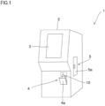
- Fig. 1 is a perspective view showing the exterior construction of a blood analysis apparatus 1 according to the embodiment.
- the blood analysis apparatus 1 includes an information display portion 3 in an upper part of the front face of an apparatus body 2.
- the display portion 3 is configured with, for example, a liquid crystal display device with a touch panel, and displays the results of blood analysis and the like and also accepts the input of various kinds of information by an operator (e.g., a medical professional).
- a container loading portion 4 is provided in a lower part of the apparatus body 2. Opening a cover 4a of the container loading portion 4, then setting a container 10 holding a blood sample (hereinafter, referred to simply as blood) in it, and then closing the cover 4a permits the container 10 to be loaded in the apparatus body 2.
- the container 10 may be loaded in the apparatus body 2 with an adapter that suits the type of container 10 attached to it.
- a reagent container loading portion 5 is provided in a side part of the apparatus body 2. Opening a door 5a of the reagent container loading portion 5 permits refilling with a reagent (e.g., a reagent for immunoassay) used in blood analysis.
- a reagent e.g., a reagent for immunoassay
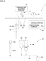
- Fig. 2 is an illustrative diagram schematically showing the internal configuration of the blood analysis apparatus 1.
- the blood analysis apparatus 1 includes a needle 20, a blood analysis portion 30, and a control portion 40.
- the control portion 40 is configured with, for example, a central arithmetic processor (computer) generally called a CPU (central processing unit) and controls the operation of different parts in the blood analysis apparatus 1.
- a central arithmetic processor computer
- CPU central processing unit
- the needle 20 is a suction tube that sucks the sample (blood) from the container 10 and discharges the sucked sample into an analysis chamber 31, which will be described later. That is, the needle 20 sucks and discharges the blood contained in the container 10.
- the needle 20 is one example of a sucking portion SU that is a cleaning target of a cleaning device 60, described later.
- the container 10 is a container that permits blood to be collected (sampled) with a lid 10b fitted to a container body 10a, and it is also referred to as a vacuum blood collection tube. With the tip end of the needle 20 pierced into the lid 10b of the container 10, the blood inside can be sucked.
- the base end of the needle 20 is connected to a quantitative syringe 22 via a first pipe 21 indicated by broken lines and an electromagnetic valve device (not shown).
- the control portion 40 drives the quantitative syringe 22 and the electromagnetic valve device, the needle 20 sucks and discharges the blood.
- the needle 20 is moved by a probe unit 23 (driving portion) in horizontal and vertical directions.
- the probe unit 23 is configured to include a horizontal moving mechanism 24 and a vertical moving mechanism 25.
- the horizontal moving mechanism 24 and the vertical moving mechanism 25 are, for example, configured with a feed screw mechanism.
- the feed screw mechanism rotates a feed screw with a stepping motor and thereby moves an engaging portion that engages with the feed screw in the horizontal or vertical direction. Coupling the vertical moving mechanism 25 with the engaging portion of the horizontal moving mechanism 24 and making the engaging portion of the vertical moving mechanism 25 hold the needle 20 permits the needle 20 to be moved in the horizontal and vertical directions.
- the horizontal moving mechanism 24 and the vertical moving mechanism 25 may be configured to include, for example, an endless belt, driving and driven rollers that run the endless belt, and the like.
- the control portion 40 drives the driving rollers in the horizontal and vertical moving mechanisms 24 and 25, the endless belt in the horizontal moving mechanism 24 runs in the horizontal direction, and the endless belt in the vertical moving mechanism 25 runs in the vertical direction. This permits the needle 20 supported on the vertical moving mechanism 25 to move in the horizontal and vertical directions.
- the blood analysis portion 30 analyzes blood as by counting blood cells and performing immunoassay.
- the blood analysis portion 30 includes a chamber 31 (container) that receives the blood sucked from the container 10 and discharged into it with the needle 20.
- a chamber 31 container
- a counting device Inside the chamber 31 for blood cell counting, a counting device is provided.
- the counting device can carry out, according to the type of blood cells to be counted, various measurement methods including those based on impedance, flow cytometry, and focused flow impedance.
- the control portion 40 can process the measurement data acquired in the counting device to create a frequency distribution or the like. Processing of the measurement data described above is performed in a calculation portion 40a included in the control portion 40.
- the blood analysis apparatus 1 includes a chamber 31 (analysis chamber) for analyzing a sample (blood).
- the counting device described above may be provided outside the chamber 31 and connected to the chamber 31.
- a plurality of reagent containers are provided.
- the reagent containers contain a hemolytic reagent, a buffer solution, an antihuman CRP sensitized latex immunoassay reagent, and the like.
- the reagents are sucked from the reagent containers with the needle 20 with appropriate timing and are discharged into the chamber.
- the blood analysis portion 30 further includes a cleaning chamber 32.
- the cleaning chamber 32 receives cleaning solution dropping from above.
- the cleaning chamber 32 also receives it.
- the cleaning device 60 is supported on the probe unit 23 and moves horizontally with the horizontal movement of the needle 20 driven by the probe unit 23. As the probe unit 23 is driven, the needle 20 moves vertically relative to the cleaning device 60.
- a discharge pipe 33 is connected as indicated by broken lines.
- the waste liquid in the chambers is, as a discharge portion (not shown) is driven, sent to a waste liquid container 50 via an electromagnetic valve device (not shown).
- the discharge portion is configured with a discharge syringe or a discharge pump.
- the control portion 40 drives the probe unit 23 to move the needle 20 in the horizontal and vertical directions. This permits the needle 20 to move into and out of each of the container 10, the chamber 31, and the reagent container.
- the control portion 40 can drive the quantitative syringe 22 to suck the blood or the reagent through the needle 20 or to discharge the blood or the reagent from the needle 20.
- blood analysis blood cell counting and immunoassay is performed in the blood analysis portion 30.
- the blood analysis apparatus 1 further includes a temperature adjusting portion 41.
- the temperature adjusting portion 41 is connected to, for example, a second pipe 26 that branches off the first pipe 21.
- a switching valve 27 is provided to switch flow paths.
- the temperature adjusting portion 41 warms a diluent contained in a tank (also referred to as a buffer tank) with a heater wound around it.
- the warmed diluent flows into the first pipe 21 via the second pipe 26 and the switching valve 27, and is then discharged into the chamber 31 through the needle 20.
- the blood previously sucked from the container 10 with the needle 20 is discharged into the chamber 31 together with the warmed diluent.
- the discharged blood is warmed to a desired temperature by mixing with the warmed diluent.
- the temperature adjusting portion 41 may be configured to warm the blood in the chamber 31 by directly heating the chamber 31 with a heater or the like. By warming the blood to a desired temperature in this way, it is possible to prevent the coagulation of blood, which coagulates under cool or cold conditions.
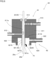
- Fig. 3 is a sectional view showing an outline of the structure of the cleaning device 60.
- the cleaning device 60 is a device for cleaning the sucking portion SU and includes a first cleaning portion 61 and a second cleaning portion 62.
- the sucking portion SU which is the cleaning target of the cleaning device 60, includes, in addition to the needle 20 described above, also a barrel 621, which will be described later. That is, the sucking portion SU includes the needle 20 and the barrel 621.
- the direction of movement of the needle 20 driven by the probe unit 23 (see Fig. 2 ) with respect to the cleaning device 60 is assumed to be the up-down direction.
- the direction in which the needle 20 moves toward the container 10 (see Fig. 2 ) for suction of blood is assumed to be "down(ward)", and the opposite direction (the direction away from the container 10) is assumed to be "up(ward)” .
- the first and the second cleaning portions 61 and 62 are positioned one above the other. More specifically, the second cleaning portion 62 is positioned below the first cleaning portion 61.
- the first and second cleaning portions 61 and 62 may be integrally constructed, or they may be constructed with separate members bonded (coupled) together.
- the first cleaning portion 61 includes a cleaning block 611, a first cleaning solution supply passage 612, and a cleaning solution discharge passage 613.
- the cleaning block 611 is a block that has a first passage portion 611a inside which the needle 20 moves.
- the first passage portion 611a has an inner diameter larger than the outer diameter of the needle 20 and is provided along the up-down direction. More specifically, the first passage portion 611a extends so as to penetrate the cleaning block 611 in the up-down direction. Thus, the first passage portion 611a is open at both its ends in the up-down direction.
- a seal member 614 is provided in an upper end part of the first passage portion 611a in the cleaning block 611. The seal member 614, while holding the needle 20, seals the upper end of the first passage portion 611a.
- the first cleaning solution supply passage 612 and the cleaning solution discharge passage 613 connect to (intersect with) the first passage portion 611a at different positions in the cleaning block 611. More specifically, the first cleaning solution supply passage 612 is located below the cleaning solution discharge passage 613 in the cleaning block 611.
- the first cleaning solution supply passage 612 and the cleaning solution discharge passage 613 extend in a direction (for example, horizontal direction) crossing the up-down direction.
- the first cleaning solution supply passage 612 is connected to a cleaning solution container (not shown). Thus, through the first cleaning solution supply passage 612 passes the cleaning solution (first cleaning solution) supplied from the cleaning solution container.
- the cleaning solution container may be the buffer tank mentioned above.
- the cleaning solution the diluent stored in the buffer tank can be used.
- the cleaning solution is not limited to a diluent and may be any other liquid (such as water).
- the cleaning solution discharge passage 613 is connected to, for example, the waste liquid container 50 (see Fig. 2 ). The cleaning liquid (first cleaning liquid) discharged from the cleaning solution discharge passage 613 flows toward the waste liquid container 50.
- the second cleaning portion 62 includes the barrel 621 and a wall portion 622.
- the barrel 621 is one example of a hollow body with a circular cross-sectional outline. As the hollow body, it is also possible to use a polygonal cylinder with a polygonal cross-sectional outline.
- the barrel 621 has a second passage portion 621a.
- the second passage portion 621a extends so as to penetrate the barrel 621 in the up-down direction. Thus, the second passage portion 621a is open at both its ends in the up-down direction.
- the second passage portion 621a is connected to the first passage portion 611a of the first cleaning portion 61 in the up-down direction.
- the barrel 621 projects downward from a bottom face 611D of the cleaning block 611 of the first cleaning portion 61. That is, the barrel 621 extends along the up-down direction.
- the second passage portion 621a has an inner diameter larger than the outer diameter of the needle 20. The needle 20 moves inside the second passage portion 621a.
- the barrel 621 is formed of metal such as SUS (stainless steel). That is, the barrel 621 includes metal.
- the barrel 621 is bonded to the bottom face 611D of the cleaning block 611.
- the barrel 621 may be press-fitted into a lower part of the cleaning block 611 so that the second passage portion 621a connects to the first passage portion 611a.
- the metal constituting the barrel 621 is not limited to SUS, but is preferably a metal that has corrosion resistance to the cleaning solution.
- the barrel 621 may be formed of resin.
- the wall portion 622 is located on the same side as the barrel 621 with respect to the cleaning block 611 of the first cleaning portion 61, that is, below the cleaning block 611.
- the wall portion 622 has an inner side face 622S and a second cleaning solution supply passage 623.
- the inner side face 622S is located away, at a gap T, from an outer circumferential face 621S that constitutes the outer face of the barrel 621. More specifically, the inner side face 622S surrounds, across the gap T, the outer circumferential face 621S of the barrel 621.
- a groove G is formed around the outer circumferential face 621S of the barrel 621.
- Fig. 4 is a bottom view of the second cleaning portion 62 as seen from below, that is, as seen from the side opposite from the first cleaning portion 61 (see Fig. 3 ).
- the outer circumferential face 621S which is the outer surface of the barrel 621, is circular, and also the inner side face 622S of the wall portion 622 is circular.
- the inner diameter of the inner side face 622S is larger than the outer diameter of the outer circumferential face 621S.
- the groove G mentioned above has its top face on the bottom face 611D of the cleaning block 611, has its side faces on the outer circumferential face 621S of the barrel 621 and the inner side face 622S of the wall portion 622, and is open downward; it is thus formed in an annular shape along the outer circumferential face 621S of the barrel 621.
- the second cleaning solution supply passage 623 extends so as to penetrate the inner side face 622S.
- the second cleaning solution supply passage 623 extends in a direction (for example, horizontal direction) intersecting with the up-down direction.
- the second cleaning solution supply passage 623 extends along a direction tangential at a point A to the inner side face 622S of the wall portion 622.
- FIG. 5 is a flow chart showing the steps involved in the cleaning of the needle 20 after the suction of blood.
- the probe unit 23 is driven so that the needle 20 is moved from the state shown in Fig. 3 downward.
- the needle 20 With a tip end portion 20b of the needle 20 pierced through the lid 10b (see Fig. 2 ) of the container 10, the blood is sucked with the needle 20.
- the probe unit 23 is driven to move the needle 20 upward so that the needle 20 is taken out of the container 10 and retracted into the first passage portion 611a in the first cleaning portion 61 via the second passage portion 621a in the second cleaning portion 62 (S 1; retraction step).
- the probe unit 23 is driven so that the needle 20 is moved horizontally together with the cleaning device 60 to above the cleaning chamber 32.
- a first cleaning solution for example, diluent
- S2 first cleaning solution supply step
- the first passage portion 611a is filled with the cleaning solution, and this permits an outer circumferential face 20a (see Fig. 3 ) of the needle 20 in the first passage portion 611a to be cleaned with the first cleaning solution.
- Supplying the first cleaning solution to the first passage portion 611a while retracting the needle 20 into the first passage portion 611a permits the outer circumferential face 20a of the needle 20 to be cleaned over a wide range in the up-down direction, and also permits the tip end portion 20b (see Fig. 3 ) of the needle 20 to be cleaned.
- the first cleaning solution supplied to the first passage portion 611a is discharged through the cleaning solution discharge passage 613 (S3; cleaning solution discharge step).
- S3 cleaning solution discharge step
- the soiled first cleaning solution used for cleaning the needle 20 in the first passage portion 611a to be discharged to the outside (for example, to the waste liquid container 50, see Fig. 2 ) via the cleaning solution discharge passage 613.
- Fig. 6 schematically shows, with arrows, the flow path through which the first cleaning solution passes when S1 to S3 are performed in parallel.
- the cleaning solution discharge passage 613 is located above the first cleaning solution supply passage 612; thus, the first cleaning solution supplied from the first cleaning solution supply passage 612 into the first passage portion 611a and soiled from cleaning flows into the cleaning solution discharge passage 613 above.
- the first cleaning solution soiled from cleaning is very unlikely to flow along the outer circumferential face 20a of the needle 20 downward to soil the outer circumferential face 20a.
- Fig. 6 shows a state where foreign matter 70 has adhered to the outer circumferential face 621S of the barrel 621.
- the needle 20 is moved downward by the probe unit 23, so that the tip end potion 20b of the needle 20 projects downward beyond a bottom end face 621D of the barrel 621.
- a second cleaning solution is supplied into the gap T between the outer circumferential face 621S of the barrel 621 and the inner side face 622S of the wall portion 622 from the second cleaning solution supply passage 623 (S4; second cleaning solution supply step).
- the second cleaning solution is supplied from the second cleaning solution supply passage 623 into the groove G.
- the second cleaning solution may be the same cleaning solution as, or a different cleaning solution from, the first cleaning solution.
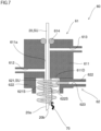
- Fig. 7 schematically shows, with arrows, the path through which the second cleaning solution flows.
- the first cleaning solution is supplied from the first cleaning solution supply passage 612 to the first passage portion 611a (S5; first cleaning solution re-supply step). At this time, the discharge of the first cleaning solution from the cleaning solution discharge passage 613 is stopped.
- the first cleaning solution supplied from the first cleaning solution supply passage 612 to the first passage portion 611a flows downward through the first passage portion 611a, then drops from the second passage portion 621a of the barrel 621 downward, and is then collected in the cleaning chamber 32.
- the cleaning device 60 and the cleaning method according to this embodiment even if, after suction of blood, foreign matter 70 adheres to the needle 20 and it adheres to the outer circumferential face 621S of the barrel 621 of the second cleaning portion 62 when the needle 20 is retracted into the first passage portion 611a in the first cleaning portion 61, by supplying cleaning solution (second cleaning solution) to the gap T (groove G) from the second cleaning solution supply passage 623, it is possible to clean the outer circumferential face 621S of the barrel 621 and remove the foreign matter 70. Thus, it is possible to reduce the risk of foreign matter 70 adversely affecting subsequent blood analysis (as by lowering analysis accuracy).
- the outer circumferential face 621S of the barrel 621 is circular, and also the inner side face 622S of the wall portion 622 is circular.
- the annular groove G is formed between the outer circumferential face 621S of the barrel 621 and the inner side face 622S of the wall portion 622.
- the cleaning solution supplied from the second cleaning solution supply passage 623 to the gap T (groove G) flows in the groove G while swirling (see Fig. 7 ).
- This swirling flow of the cleaning solution effectively removes foreign matter 70 adhering to the outer circumferential face 621S of the barrel 621. That is, by making the cleaning solution supplied to the gap T through the second cleaning solution supply passage 623 swirl around the outer circumferential face 621S of the barrel 621, it is possible to efficiently remove foreign matter 70 adhering to the outer circumferential face 621S of the barrel 621.
- the barrel 621 includes metal. This ensures the mechanical strength of the barrel 621, and makes it possible to reduce the thickness of the barrel 621. For example, the thickness of the barrel 621 can be reduced down to about 0.2 to 0.3 mm. Thus, it is possible to reduce the area of the bottom end face 621D of the barrel 621 (the face that intersects with the outer circumferential face 621S of the barrel 621 and that is perpendicular to the movement direction of the needle 20) and thereby reduce the adhesion of foreign matter to the bottom end face 621D. Thus, it is possible to remove a large part of the foreign matter 70 adhering to the barrel 621 by cleaning the outer circumferential face 621S of the barrel 621, and this increases the efficiency of removing foreign matter 70.
- the needle 20 used in this embodiment is a suction tube with a tip end potion 20b that can penetrate the lid 10b of the container 10.
- suction tubes are also called suction tubes of a single-pierce type.
- a sample blood
- suction tube of a single-pierce type When the suction tube is taken out of the container 10, foreign matter 70 adhering to the top face of the lid 10b of the container 10 for some reason may adhere to the suction tube and, when the suction tube is retracted into the cleaning device 60, the foreign matter 70 may adhere to the outer circumferential face 621S of the barrel 621.
- the cleaning device 60 of this embodiment is highly effective when sampling is performed using such a suction tube of a single-pierce type.
- the blood analysis apparatus 1 as the sample analysis apparatus of this embodiment includes the cleaning device 60 with the configuration described above, the analysis chamber 31 for analyzing a sample (e.g., blood), and the needle 20 for sucking the sample and discharging it into the chamber 31. Even if foreign matter 70 adheres to the cleaning device 60 (e.g., the outer circumferential face 621S of the barrel 621) after suction of a sample (sampling), the foreign matter 70 can be removed by the cleaning device 60; thus, it is possible to avoid a drop in the analysis accuracy of the blood analysis apparatus 1.
- a sample e.g., blood
- the needle 20 for sucking the sample and discharging it into the chamber 31.
- the blood analysis apparatus 1 of this embodiment includes the probe unit 23 as a driving portion to move the needle 20 (in the up-down direction) with respect to the first and second passage portions 611a and 621a of the cleaning device 60. This permits the outer circumferential face 20a and the tip end potion 20b of the needle 20 to be retracted into the first passage portion 611a so that the needle 20 is cleaned.
- the second cleaning solution in the second cleaning solution supply step (S4), with the tip end potion 20b of the needle 20 projecting beyond the end face (bottom end face 621D), opposite from the first cleaning portion 61, of the barrel 621, the second cleaning solution is supplied to the gap T.
- the second cleaning solution drops downward into the cleaning chamber 32 from the outer circumferential face 621S of the barrel 621 along the outer circumferential face 20a of the needle 20.
- the second cleaning solution supplied to the gap T can be efficiently collected without it being scattered around.
- the cleaning of the needle 20 by the cleaning device 60 proceeds in the order of cleaning by the first cleaning portion 61 and cleaning by the second cleaning portion 62, it may instead proceed in the order of cleaning by the second cleaning portion 62 and cleaning by the first cleaning portion 61; or cleaning by the first and second cleaning portions 61 and 62 may proceed concurrently.
- the cleaning device 60 of this embodiment can also be applied to, for example, the cleaning of a suction tube of a double-needle type.
- the above embodiment deals with an example of using as the container 10 a container of a closed type with the lid 10b fitted to the container body 10a, also when a container 10 of an open type that is loaded in the blood analysis apparatus 1 with no lid is used, blood is sampled from the container 10 with the needle 20, and the needle 20 is soiled, cleaning the needle 20 with the cleaning device 60 of the embodiment helps reduce the risk of a drop in analytical accuracy.
- the sample can be anything other than blood.
- the sample can be any of body fluids such as plasma, serum, saliva, urine, lymphatic fluid, and cerebrospinal fluid.
- the cleaning device 60 described in this embodiment can be applied also to devices for analyzing samples like plasma.
- the present invention finds applications in, for example, sample analysis apparatuses such as blood analysis apparatuses.
Landscapes
- Chemical & Material Sciences (AREA)
- Health & Medical Sciences (AREA)
- General Health & Medical Sciences (AREA)
- General Physics & Mathematics (AREA)
- Physics & Mathematics (AREA)
- Life Sciences & Earth Sciences (AREA)
- Analytical Chemistry (AREA)
- Biochemistry (AREA)
- Clinical Laboratory Science (AREA)
- Chemical Kinetics & Catalysis (AREA)
- Immunology (AREA)
- Pathology (AREA)
- Cleaning In General (AREA)
- Cleaning By Liquid Or Steam (AREA)
- Sampling And Sample Adjustment (AREA)
- Automatic Analysis And Handling Materials Therefor (AREA)
Abstract
Description
- The present invention relates to a cleaning device that cleans a suction portion, a sample analysis apparatus, and a cleaning method.
- There are conventionally known sample analysis apparatuses that analyze a sample (for example, blood) sucked with a suction tube. In a sample analysis apparatus, after the suction tube is pierced through the lid of a container to suck a sample inside the container, it is raised up to inside a cleaning device located above to be cleaned. Then, the suction tube moves along with the cleaning device to a predetermined discharge position, and then descends from the cleaning device to discharge the sample into an analysis chamber. In this way, analysis of the sample (such as counting blood cells) is performed in the analysis chamber. For example, Patent Document 1 discloses one example of a cleaning device as described above.
- Patent Document 1:
JP-A-H6-222065 - If foreign matter (such as a blood clot) adheres to the upper face of the lid of the container, the foreign matter may adhere to the suction tube when, after suction of the sample with the suction tube, the suction tube is raised and taken out of the container. Then, when the suction tube is retracted into the cleaning device, the foreign matter mentioned above may adhere to the lower end face of the cleaning device. In particular, in a construction like that of the cleaning device of Patent Document 1 where a projection projecting downward is provided on the lower end face and the suction tube moves inside that projection, foreign matter may adhere to the outer circumferential face of the projection. Then, the foreign matter may fall into the analysis chamber and mix with the sample. That is, the foreign matter may adversely affect the analysis of the sample (as by lowering analysis accuracy).
- Patent Document 1 does not discuss a measure to cope with foreign matter adhered to the cleaning device as mentioned above.
- The present invention is devised to solve the above-mentioned problem and aims at providing a cleaning device, a sample analysis apparatus, and a cleaning method that can, even if foreign matter adheres to a suction tube after the suction of a sample and it adheres to the cleaning device as the suction tube moves, reduce the risk of the foreign matter adversely affecting the analysis of the sample.
- According to one aspect of the present invention, a cleaning device that cleans a suction portion includes: a first passage portion inside which a suction tube for sucking a sample moves; a first cleaning solution supply passage and a cleaning solution discharge passage that intersect with the first passage portion; a hollow body that connects to the first passage portion in the movement direction of the suction tube and that has a second passage portion inside which the suction tube moves; and a wall portion having an inner side face that surrounds the outer side face of the hollow body across a gap. The suction portion includes the suction tube and the hollow body. The wall portion has a second cleaning solution supply passage that penetrates the inner side face. The cleaning device cleans at least one of the suction tube and the hollow body.
- According to another aspect of the present invention, a sample analysis apparatus includes the cleaning device described above, an analysis chamber for analyzing the sample, and the suction tube that sucks the sample and discharges it into the analysis chamber.
- According to yet another aspect of the present invention, a cleaning method includes a retraction step of, after suction of a sample with a suction tube, retracting the suction tube into a first passage portion of a cleaning device via a second passage portion of a hollow body in the cleaning device; a first cleaning solution supply step of supplying a first cleaning solution from a first cleaning solution supply passage in the cleaning device to the first passage portion; a cleaning solution discharge step of discharging the first cleaning solution supplied to the first passage portion through a cleaning solution discharge passage in the cleaning device; and a second cleaning solution supply step of supplying a second cleaning solution from a second cleaning solution supply passage that penetrates an inner side face of a wall portion that surrounds the outer side face of the hollow body into a gap between an outer circumferential face of the hollow body and the inner side face.
- According to the present invention, even if foreign matter adheres to a suction tube after the suction of a sample and it adheres to the cleaning device as the suction tube moves, it is possible to reduce the risk of foreign matter adversely affecting the analysis of a sample.
-
- [
Fig. 1 ] is a perspective view showing the exterior construction of a blood analysis apparatus according to one embodiment of the present invention. - [
Fig. 2 ] is an illustrative diagram schematically showing the internal configuration of the blood analysis apparatus. - [
Fig. 3 ] is a sectional view showing an outline of the structure of a cleaning device included in the blood analysis apparatus. - [
Fig. 4 ] is a bottom view of a second cleaning portion of the cleaning device as seen from below. - [
Fig. 5 ] is a flow chart showing the steps involved in the cleaning of a needle after the suction of blood. - [
Fig. 6 ] is an illustrative diagram schematically showing a flow path in the cleaning device through which a first cleaning solution passes from a first cleaning solution supply passage to a cleaning solution discharge passage. - [
Fig. 7 ] is an illustrative diagram schematically showing a flow path in the cleaning device through which a second cleaning solution passes. - [
Fig. 8 ] is an illustrative diagram schematically showing a flow path in the cleaning device through which the first cleaning solution flows downward through the first and second flow passages. - An illustrative embodiment of the present invention will be described below with reference to the accompanying drawings. In the following description, blood (whole blood) is assumed as one example of a sample, and a blood analysis apparatus for analyzing blood is assumed as one example of a sample analysis apparatus.
-
Fig. 1 is a perspective view showing the exterior construction of a blood analysis apparatus 1 according to the embodiment. The blood analysis apparatus 1 includes aninformation display portion 3 in an upper part of the front face of anapparatus body 2. Thedisplay portion 3 is configured with, for example, a liquid crystal display device with a touch panel, and displays the results of blood analysis and the like and also accepts the input of various kinds of information by an operator (e.g., a medical professional). - In a lower part of the
apparatus body 2, acontainer loading portion 4 is provided. Opening acover 4a of thecontainer loading portion 4, then setting acontainer 10 holding a blood sample (hereinafter, referred to simply as blood) in it, and then closing thecover 4a permits thecontainer 10 to be loaded in theapparatus body 2. Thecontainer 10 may be loaded in theapparatus body 2 with an adapter that suits the type ofcontainer 10 attached to it. - In a side part of the
apparatus body 2, a reagentcontainer loading portion 5 is provided. Opening adoor 5a of the reagentcontainer loading portion 5 permits refilling with a reagent (e.g., a reagent for immunoassay) used in blood analysis. -
Fig. 2 is an illustrative diagram schematically showing the internal configuration of the blood analysis apparatus 1. The blood analysis apparatus 1 includes aneedle 20, ablood analysis portion 30, and acontrol portion 40. Thecontrol portion 40 is configured with, for example, a central arithmetic processor (computer) generally called a CPU (central processing unit) and controls the operation of different parts in the blood analysis apparatus 1. - The
needle 20 is a suction tube that sucks the sample (blood) from thecontainer 10 and discharges the sucked sample into ananalysis chamber 31, which will be described later. That is, theneedle 20 sucks and discharges the blood contained in thecontainer 10. Theneedle 20 is one example of a sucking portion SU that is a cleaning target of acleaning device 60, described later. - Here, the
container 10 is a container that permits blood to be collected (sampled) with alid 10b fitted to acontainer body 10a, and it is also referred to as a vacuum blood collection tube. With the tip end of theneedle 20 pierced into thelid 10b of thecontainer 10, the blood inside can be sucked. - The base end of the
needle 20 is connected to aquantitative syringe 22 via afirst pipe 21 indicated by broken lines and an electromagnetic valve device (not shown). As thecontrol portion 40 drives thequantitative syringe 22 and the electromagnetic valve device, theneedle 20 sucks and discharges the blood. - The
needle 20 is moved by a probe unit 23 (driving portion) in horizontal and vertical directions. Theprobe unit 23 is configured to include ahorizontal moving mechanism 24 and avertical moving mechanism 25. Thehorizontal moving mechanism 24 and thevertical moving mechanism 25 are, for example, configured with a feed screw mechanism. The feed screw mechanism rotates a feed screw with a stepping motor and thereby moves an engaging portion that engages with the feed screw in the horizontal or vertical direction. Coupling the vertical movingmechanism 25 with the engaging portion of the horizontal movingmechanism 24 and making the engaging portion of the vertical movingmechanism 25 hold theneedle 20 permits theneedle 20 to be moved in the horizontal and vertical directions. - The
horizontal moving mechanism 24 and the vertical movingmechanism 25 may be configured to include, for example, an endless belt, driving and driven rollers that run the endless belt, and the like. As thecontrol portion 40 drives the driving rollers in the horizontal and vertical movingmechanisms mechanism 24 runs in the horizontal direction, and the endless belt in the vertical movingmechanism 25 runs in the vertical direction. This permits theneedle 20 supported on the vertical movingmechanism 25 to move in the horizontal and vertical directions. - The
blood analysis portion 30 analyzes blood as by counting blood cells and performing immunoassay. Theblood analysis portion 30 includes a chamber 31 (container) that receives the blood sucked from thecontainer 10 and discharged into it with theneedle 20. There are provided asmany chambers 31 as the number of targets to be counted, such as red blood cells, white blood cells (including what is classified as white blood cells), CRP, etc. - Inside the
chamber 31 for blood cell counting, a counting device is provided. The counting device can carry out, according to the type of blood cells to be counted, various measurement methods including those based on impedance, flow cytometry, and focused flow impedance. Thecontrol portion 40 can process the measurement data acquired in the counting device to create a frequency distribution or the like. Processing of the measurement data described above is performed in acalculation portion 40a included in thecontrol portion 40. In this way, the blood analysis apparatus 1 includes a chamber 31 (analysis chamber) for analyzing a sample (blood). The counting device described above may be provided outside thechamber 31 and connected to thechamber 31. - Near the CRP measuring chamber, a plurality of reagent containers (not shown) are provided. The reagent containers contain a hemolytic reagent, a buffer solution, an antihuman CRP sensitized latex immunoassay reagent, and the like. In performing CRP measurement, the reagents are sucked from the reagent containers with the
needle 20 with appropriate timing and are discharged into the chamber. - The
blood analysis portion 30 further includes acleaning chamber 32. During the cleaning of theneedle 20 by thecleaning device 60, which will be described later, the cleaningchamber 32 receives cleaning solution dropping from above. When excess blood is discharged from theneedle 20, the cleaningchamber 32 also receives it. - The
cleaning device 60 is supported on theprobe unit 23 and moves horizontally with the horizontal movement of theneedle 20 driven by theprobe unit 23. As theprobe unit 23 is driven, theneedle 20 moves vertically relative to thecleaning device 60. - To lower end parts of the chambers described above, that is, the analysis chamber (chamber 31) and the
cleaning chamber 32, adischarge pipe 33 is connected as indicated by broken lines. The waste liquid in the chambers is, as a discharge portion (not shown) is driven, sent to awaste liquid container 50 via an electromagnetic valve device (not shown). The discharge portion is configured with a discharge syringe or a discharge pump. - When the
container 10 containing blood is loaded in the container loading portion 4 (seeFig. 1 ) in theapparatus body 2, thecontrol portion 40 drives theprobe unit 23 to move theneedle 20 in the horizontal and vertical directions. This permits theneedle 20 to move into and out of each of thecontainer 10, thechamber 31, and the reagent container. In addition, thecontrol portion 40 can drive thequantitative syringe 22 to suck the blood or the reagent through theneedle 20 or to discharge the blood or the reagent from theneedle 20. Through such operations, blood analysis (blood cell counting and immunoassay) is performed in theblood analysis portion 30. - The blood analysis apparatus 1 further includes a
temperature adjusting portion 41. Thetemperature adjusting portion 41 is connected to, for example, asecond pipe 26 that branches off thefirst pipe 21. In a branch portion between thefirst pipe 21 and thesecond pipe 26, a switchingvalve 27 is provided to switch flow paths. Thetemperature adjusting portion 41 warms a diluent contained in a tank (also referred to as a buffer tank) with a heater wound around it. The warmed diluent flows into thefirst pipe 21 via thesecond pipe 26 and the switchingvalve 27, and is then discharged into thechamber 31 through theneedle 20. Here, also the blood previously sucked from thecontainer 10 with theneedle 20 is discharged into thechamber 31 together with the warmed diluent. Thus, in thechamber 31, the discharged blood is warmed to a desired temperature by mixing with the warmed diluent. Thetemperature adjusting portion 41 may be configured to warm the blood in thechamber 31 by directly heating thechamber 31 with a heater or the like. By warming the blood to a desired temperature in this way, it is possible to prevent the coagulation of blood, which coagulates under cool or cold conditions. - Next, the
cleaning device 60 included in the blood analysis apparatus 1 of this embodiment will be described in detail.Fig. 3 is a sectional view showing an outline of the structure of thecleaning device 60. Thecleaning device 60 is a device for cleaning the sucking portion SU and includes afirst cleaning portion 61 and asecond cleaning portion 62. The sucking portion SU, which is the cleaning target of thecleaning device 60, includes, in addition to theneedle 20 described above, also abarrel 621, which will be described later. That is, the sucking portion SU includes theneedle 20 and thebarrel 621. - For convenience' sake, in the following description, the direction of movement of the
needle 20 driven by the probe unit 23 (seeFig. 2 ) with respect to thecleaning device 60 is assumed to be the up-down direction. The direction in which theneedle 20 moves toward the container 10 (seeFig. 2 ) for suction of blood is assumed to be "down(ward)", and the opposite direction (the direction away from the container 10) is assumed to be "up(ward)" . - The first and the
second cleaning portions second cleaning portion 62 is positioned below thefirst cleaning portion 61. The first andsecond cleaning portions - The
first cleaning portion 61 includes acleaning block 611, a first cleaningsolution supply passage 612, and a cleaningsolution discharge passage 613. Thecleaning block 611 is a block that has afirst passage portion 611a inside which theneedle 20 moves. Thefirst passage portion 611a has an inner diameter larger than the outer diameter of theneedle 20 and is provided along the up-down direction. More specifically, thefirst passage portion 611a extends so as to penetrate thecleaning block 611 in the up-down direction. Thus, thefirst passage portion 611a is open at both its ends in the up-down direction. Aseal member 614 is provided in an upper end part of thefirst passage portion 611a in thecleaning block 611. Theseal member 614, while holding theneedle 20, seals the upper end of thefirst passage portion 611a. - The first cleaning
solution supply passage 612 and the cleaningsolution discharge passage 613 connect to (intersect with) thefirst passage portion 611a at different positions in thecleaning block 611. More specifically, the first cleaningsolution supply passage 612 is located below the cleaningsolution discharge passage 613 in thecleaning block 611. The first cleaningsolution supply passage 612 and the cleaningsolution discharge passage 613 extend in a direction (for example, horizontal direction) crossing the up-down direction. - The first cleaning
solution supply passage 612 is connected to a cleaning solution container (not shown). Thus, through the first cleaningsolution supply passage 612 passes the cleaning solution (first cleaning solution) supplied from the cleaning solution container. Here, the cleaning solution container may be the buffer tank mentioned above. In this case, as the cleaning solution, the diluent stored in the buffer tank can be used. The cleaning solution is not limited to a diluent and may be any other liquid (such as water). The cleaningsolution discharge passage 613 is connected to, for example, the waste liquid container 50 (seeFig. 2 ). The cleaning liquid (first cleaning liquid) discharged from the cleaningsolution discharge passage 613 flows toward thewaste liquid container 50. - The
second cleaning portion 62 includes thebarrel 621 and awall portion 622. Thebarrel 621 is one example of a hollow body with a circular cross-sectional outline. As the hollow body, it is also possible to use a polygonal cylinder with a polygonal cross-sectional outline. Thebarrel 621 has asecond passage portion 621a. Thesecond passage portion 621a extends so as to penetrate thebarrel 621 in the up-down direction. Thus, thesecond passage portion 621a is open at both its ends in the up-down direction. - The
second passage portion 621a is connected to thefirst passage portion 611a of thefirst cleaning portion 61 in the up-down direction. Thebarrel 621 projects downward from abottom face 611D of thecleaning block 611 of thefirst cleaning portion 61. That is, thebarrel 621 extends along the up-down direction. Thesecond passage portion 621a has an inner diameter larger than the outer diameter of theneedle 20. Theneedle 20 moves inside thesecond passage portion 621a. - The
barrel 621 is formed of metal such as SUS (stainless steel). That is, thebarrel 621 includes metal. Thebarrel 621 is bonded to thebottom face 611D of thecleaning block 611. Thebarrel 621 may be press-fitted into a lower part of thecleaning block 611 so that thesecond passage portion 621a connects to thefirst passage portion 611a. The metal constituting thebarrel 621 is not limited to SUS, but is preferably a metal that has corrosion resistance to the cleaning solution. Thebarrel 621 may be formed of resin. - The
wall portion 622 is located on the same side as thebarrel 621 with respect to thecleaning block 611 of thefirst cleaning portion 61, that is, below thecleaning block 611. Thewall portion 622 has an inner side face 622S and a second cleaningsolution supply passage 623. The inner side face 622S is located away, at a gap T, from an outercircumferential face 621S that constitutes the outer face of thebarrel 621. More specifically, the inner side face 622S surrounds, across the gap T, the outercircumferential face 621S of thebarrel 621. Thus, a groove G is formed around the outercircumferential face 621S of thebarrel 621. -
Fig. 4 is a bottom view of thesecond cleaning portion 62 as seen from below, that is, as seen from the side opposite from the first cleaning portion 61 (seeFig. 3 ). When thesecond cleaning portion 62 is viewed from below, the outercircumferential face 621S, which is the outer surface of thebarrel 621, is circular, and also theinner side face 622S of thewall portion 622 is circular. However, the inner diameter of the inner side face 622S is larger than the outer diameter of the outercircumferential face 621S. The groove G mentioned above has its top face on thebottom face 611D of thecleaning block 611, has its side faces on the outercircumferential face 621S of thebarrel 621 and theinner side face 622S of thewall portion 622, and is open downward; it is thus formed in an annular shape along the outercircumferential face 621S of thebarrel 621. - As shown in
Figs. 3 and4 , in thewall portion 622, the second cleaningsolution supply passage 623 extends so as to penetrate theinner side face 622S. In thewall portion 622, the second cleaningsolution supply passage 623 extends in a direction (for example, horizontal direction) intersecting with the up-down direction. In particular, as shown inFig. 4 , when thesecond cleaning portion 62 is viewed from below, the second cleaningsolution supply passage 623 extends along a direction tangential at a point A to theinner side face 622S of thewall portion 622. - Next, the steps from the suction of blood by the
needle 20 to the completion of the cleaning of theneedle 20 will be described.Fig. 5 is a flow chart showing the steps involved in the cleaning of theneedle 20 after the suction of blood. - First, the
probe unit 23 is driven so that theneedle 20 is moved from the state shown inFig. 3 downward. With atip end portion 20b of theneedle 20 pierced through thelid 10b (seeFig. 2 ) of thecontainer 10, the blood is sucked with theneedle 20. - Then, the
probe unit 23 is driven to move theneedle 20 upward so that theneedle 20 is taken out of thecontainer 10 and retracted into thefirst passage portion 611a in thefirst cleaning portion 61 via thesecond passage portion 621a in the second cleaning portion 62 (S 1; retraction step). After theneedle 20 is taken out of thecontainer 10, theprobe unit 23 is driven so that theneedle 20 is moved horizontally together with thecleaning device 60 to above the cleaningchamber 32. - Then, a first cleaning solution (for example, diluent) is supplied from the first cleaning
solution supply passage 612 to thefirst passage portion 611a (S2; first cleaning solution supply step). Thus, thefirst passage portion 611a is filled with the cleaning solution, and this permits an outercircumferential face 20a (seeFig. 3 ) of theneedle 20 in thefirst passage portion 611a to be cleaned with the first cleaning solution. Supplying the first cleaning solution to thefirst passage portion 611a while retracting theneedle 20 into thefirst passage portion 611a permits the outercircumferential face 20a of theneedle 20 to be cleaned over a wide range in the up-down direction, and also permits thetip end portion 20b (seeFig. 3 ) of theneedle 20 to be cleaned. - Concurrently with S2, the first cleaning solution supplied to the
first passage portion 611a is discharged through the cleaning solution discharge passage 613 (S3; cleaning solution discharge step). This permits the soiled first cleaning solution used for cleaning theneedle 20 in thefirst passage portion 611a to be discharged to the outside (for example, to thewaste liquid container 50, seeFig. 2 ) via the cleaningsolution discharge passage 613. Thus, it is possible to keep clean the first cleaning solution filling thefirst passage portion 611a.Fig. 6 schematically shows, with arrows, the flow path through which the first cleaning solution passes when S1 to S3 are performed in parallel. - In the
cleaning block 611, the cleaningsolution discharge passage 613 is located above the first cleaningsolution supply passage 612; thus, the first cleaning solution supplied from the first cleaningsolution supply passage 612 into thefirst passage portion 611a and soiled from cleaning flows into the cleaningsolution discharge passage 613 above. In other words, the first cleaning solution soiled from cleaning is very unlikely to flow along the outercircumferential face 20a of theneedle 20 downward to soil the outercircumferential face 20a. - Incidentally, if, after blood is sucked with the
needle 20 from thecontainment container 10, foreign matter (such as a blood clot) adheres to the outercircumferential face 20a or thetip end potion 20b of theneedle 20, in step S1 described above, the foreign matter may adhere to the outercircumferential face 621S of thebarrel 621 of thesecond cleaning portion 62 when theneedle 20 is retracted into thefirst passage portion 611a.Fig. 6 shows a state whereforeign matter 70 has adhered to the outercircumferential face 621S of thebarrel 621. - Thus, in this embodiment, in S1 to S3, after the
needle 20 is cleaned in thefirst cleaning portion 61, theneedle 20 is moved downward by theprobe unit 23, so that thetip end potion 20b of theneedle 20 projects downward beyond abottom end face 621D of thebarrel 621. In this state, a second cleaning solution is supplied into the gap T between the outercircumferential face 621S of thebarrel 621 and theinner side face 622S of thewall portion 622 from the second cleaning solution supply passage 623 (S4; second cleaning solution supply step). In other words, the second cleaning solution is supplied from the second cleaningsolution supply passage 623 into the groove G. The second cleaning solution may be the same cleaning solution as, or a different cleaning solution from, the first cleaning solution. -
Fig. 7 schematically shows, with arrows, the path through which the second cleaning solution flows. With the supply of the second cleaning solution,foreign matter 70 adhering to the outercircumferential face 621S of thebarrel 621 is removed by the second cleaning solution flowing through the groove G and drops downward with the second cleaning solution to be collected in thecleaning chamber 32. In particular, in this embodiment, since the second cleaningsolution supply passage 623 extends in a tangential direction at the point A (seeFig. 4 ), the second cleaning solution supplied from the second cleaningsolution supply passage 623 to the groove G flows while swirling in the groove G. - Finally, the first cleaning solution is supplied from the first cleaning
solution supply passage 612 to thefirst passage portion 611a (S5; first cleaning solution re-supply step). At this time, the discharge of the first cleaning solution from the cleaningsolution discharge passage 613 is stopped. Thus, the first cleaning solution supplied from the first cleaningsolution supply passage 612 to thefirst passage portion 611a, as indicated by an arrow inFig. 8 , flows downward through thefirst passage portion 611a, then drops from thesecond passage portion 621a of thebarrel 621 downward, and is then collected in thecleaning chamber 32. - With the construction of the
cleaning device 60 and the cleaning method according to this embodiment, even if, after suction of blood,foreign matter 70 adheres to theneedle 20 and it adheres to the outercircumferential face 621S of thebarrel 621 of thesecond cleaning portion 62 when theneedle 20 is retracted into thefirst passage portion 611a in thefirst cleaning portion 61, by supplying cleaning solution (second cleaning solution) to the gap T (groove G) from the second cleaningsolution supply passage 623, it is possible to clean the outercircumferential face 621S of thebarrel 621 and remove theforeign matter 70. Thus, it is possible to reduce the risk offoreign matter 70 adversely affecting subsequent blood analysis (as by lowering analysis accuracy). - As seen from below, that is, on the plane perpendicular to the movement direction of the
needle 20, the outercircumferential face 621S of thebarrel 621 is circular, and also theinner side face 622S of thewall portion 622 is circular. Thus, as shown inFig. 4 , the annular groove G is formed between the outercircumferential face 621S of thebarrel 621 and theinner side face 622S of thewall portion 622. When the cleaning solution (second cleaning solution) is supplied from the second cleaningsolution supply passage 623 to the annular groove G, the cleaning solution flows along the circumferential direction of the annular groove G. Thus, no matter whereforeign matter 70 adheres to the outercircumferential face 621S of thebarrel 621, it can be removed with the supply of the cleaning solution. - As described above, the cleaning solution supplied from the second cleaning
solution supply passage 623 to the gap T (groove G) flows in the groove G while swirling (seeFig. 7 ). This swirling flow of the cleaning solution effectively removesforeign matter 70 adhering to the outercircumferential face 621S of thebarrel 621. That is, by making the cleaning solution supplied to the gap T through the second cleaningsolution supply passage 623 swirl around the outercircumferential face 621S of thebarrel 621, it is possible to efficiently removeforeign matter 70 adhering to the outercircumferential face 621S of thebarrel 621. - The
barrel 621 includes metal. This ensures the mechanical strength of thebarrel 621, and makes it possible to reduce the thickness of thebarrel 621. For example, the thickness of thebarrel 621 can be reduced down to about 0.2 to 0.3 mm. Thus, it is possible to reduce the area of thebottom end face 621D of the barrel 621 (the face that intersects with the outercircumferential face 621S of thebarrel 621 and that is perpendicular to the movement direction of the needle 20) and thereby reduce the adhesion of foreign matter to thebottom end face 621D. Thus, it is possible to remove a large part of theforeign matter 70 adhering to thebarrel 621 by cleaning the outercircumferential face 621S of thebarrel 621, and this increases the efficiency of removingforeign matter 70. - The
needle 20 used in this embodiment is a suction tube with atip end potion 20b that can penetrate thelid 10b of thecontainer 10. Such suction tubes are also called suction tubes of a single-pierce type. During sampling by sucking a sample (blood) from thecontainer 10 using a suction tube of a single-pierce type, when the suction tube is taken out of thecontainer 10,foreign matter 70 adhering to the top face of thelid 10b of thecontainer 10 for some reason may adhere to the suction tube and, when the suction tube is retracted into thecleaning device 60, theforeign matter 70 may adhere to the outercircumferential face 621S of thebarrel 621. Thus, thecleaning device 60 of this embodiment is highly effective when sampling is performed using such a suction tube of a single-pierce type. - The blood analysis apparatus 1 as the sample analysis apparatus of this embodiment includes the
cleaning device 60 with the configuration described above, theanalysis chamber 31 for analyzing a sample (e.g., blood), and theneedle 20 for sucking the sample and discharging it into thechamber 31. Even ifforeign matter 70 adheres to the cleaning device 60 (e.g., the outercircumferential face 621S of the barrel 621) after suction of a sample (sampling), theforeign matter 70 can be removed by thecleaning device 60; thus, it is possible to avoid a drop in the analysis accuracy of the blood analysis apparatus 1. - The blood analysis apparatus 1 of this embodiment includes the
probe unit 23 as a driving portion to move the needle 20 (in the up-down direction) with respect to the first andsecond passage portions cleaning device 60. This permits the outercircumferential face 20a and thetip end potion 20b of theneedle 20 to be retracted into thefirst passage portion 611a so that theneedle 20 is cleaned. - In the cleaning method of this embodiment, in the second cleaning solution supply step (S4), with the
tip end potion 20b of theneedle 20 projecting beyond the end face (bottom end face 621D), opposite from thefirst cleaning portion 61, of thebarrel 621, the second cleaning solution is supplied to the gap T. In this case, the second cleaning solution drops downward into the cleaningchamber 32 from the outercircumferential face 621S of thebarrel 621 along the outercircumferential face 20a of theneedle 20. Thus, the second cleaning solution supplied to the gap T can be efficiently collected without it being scattered around. - While, in this embodiment, the cleaning of the
needle 20 by thecleaning device 60 proceeds in the order of cleaning by thefirst cleaning portion 61 and cleaning by thesecond cleaning portion 62, it may instead proceed in the order of cleaning by thesecond cleaning portion 62 and cleaning by thefirst cleaning portion 61; or cleaning by the first andsecond cleaning portions - While, in
Fig. 7 , cleaning is performed with thetip end potion 20b of theneedle 20 projecting downward beyond thebottom end face 621D of thebarrel 621, cleaning does not necessarily need to be performed with thetip end potion 20b projecting. That is, a configuration is also possible where, through the retraction step for theneedle 20 or the like, not both of thebarrel 621 and the needle 20 (the suction portion) are cleaned (for example, only the outercircumferential face 621S of thebarrel 621 is cleaned). - While the above embodiment deals with an example where the suction tube of a single-pierce type is used as the
needle 20, thecleaning device 60 of this embodiment can also be applied to, for example, the cleaning of a suction tube of a double-needle type. - Although the above embodiment deals with an example of using as the
container 10 a container of a closed type with thelid 10b fitted to thecontainer body 10a, also when acontainer 10 of an open type that is loaded in the blood analysis apparatus 1 with no lid is used, blood is sampled from thecontainer 10 with theneedle 20, and theneedle 20 is soiled, cleaning theneedle 20 with thecleaning device 60 of the embodiment helps reduce the risk of a drop in analytical accuracy. - While the embodiment described above deals with an example where blood is used as the sample, the sample can be anything other than blood. For example, the sample can be any of body fluids such as plasma, serum, saliva, urine, lymphatic fluid, and cerebrospinal fluid. The
cleaning device 60 described in this embodiment can be applied also to devices for analyzing samples like plasma. - The description of embodiments of the present invention given above is in no way meant to limit the invention, and various modifications are possible without departing from the spirit of the present invention.
- The present invention finds applications in, for example, sample analysis apparatuses such as blood analysis apparatuses.
-
- 1
- blood analysis apparatus (sample analysis apparatus)
- 10
- container
- 10b
- lid
- 20
- needle (suction portion, suction tube)
- 20a
- outer circumferential face
- 20b
- tip end portion
- 23
- probe unit (driving portion)
- 31
- chamber (analysis chamber)
- 60
- cleaning device
- 61
- first cleaning portion
- 611
- cleaning block
- 611a
- first passage portion
- 612
- first cleaning solution supply passage
- 613
- cleaning solution discharge passage
- 62
- second cleaning portion
- 621
- barrel (suction portion, hollow body)
- 621a
- second passage portion
- 621S
- outer circumferential face (outer surface)
- 622
- wall portion
- 622S
- inner side face
- 623
- second cleaning solution supply passage
- A
- point
- T
- gap
- SU
- suction portion
Claims (10)
- A cleaning device that cleans a suction portion, comprising:a first passage portion inside which a suction tube for sucking a sample moves;a first cleaning solution supply passage and a cleaning solution discharge passage that intersect with the first passage portion;a hollow body that connects to the first passage portion in a movement direction of the suction tube, the hollow body having a second passage portion inside which the suction tube moves; anda wall portion having an inner side face that surrounds an outer side face of the hollow body across a gap,whereinthe suction portion includes the suction tube and the hollow body,the wall portion has a second cleaning solution supply passage that penetrates the inner side face, andthe cleaning device cleans at least one of the suction tube and the hollow body.
- The cleaning device according to claim 1,
wherein
a cleaning solution supplied to the gap through the second cleaning solution supply passage is made into a swirling flow that swirls around the outer side face of the hollow body. - The cleaning device according to claim 1 or 2,
wherein
on a plane perpendicular to the movement direction of the suction tube,the outer side face of the hollow body is circular, andthe inner side face of the wall portion is circular. - The cleaning device according to claim 3,
wherein
on a plane perpendicular to the movement direction of the suction tube, the second cleaning solution supply passage extends along a direction tangential at a point to the inner side face of the wall portion. - The cleaning device according to any one of claims 1 to 4,
wherein
the hollow body includes metal. - The cleaning device according to any one of claims 1 to 5,
wherein
the suction tube includes a tip end portion that can penetrate a lid of a container that stores the sample. - A sample analysis apparatus comprising:the cleaning device according to any one of claims 1 to 6;an analysis chamber for analyzing the sample; andthe suction tube that sucks the sample and discharges the sample into the analysis chamber.
- The sample analysis apparatus according to claim 7, further comprising a driving portion that moves the suction tube with respect to the first and second passage portions of the cleaning device.
- A cleaning method comprising:a retraction step of, after suction of a sample with a suction tube, retracting the suction tube into a first passage portion of a cleaning device via a second passage portion of a hollow body in the cleaning device;a first cleaning solution supply step of supplying a first cleaning solution from a first cleaning solution supply passage in the cleaning device to the first passage portion;a cleaning solution discharge step of discharging the first cleaning solution supplied to the first passage portion through a cleaning solution discharge passage in the cleaning device; anda second cleaning solution supply step of supplying a second cleaning solution from a second cleaning solution supply passage that penetrates an inner side face of a wall portion that surrounds the outer side face of the hollow body into a gap between an outer circumferential face of the hollow body and the inner side face.
- The cleaning method according to claim 9,
wherein
in the second cleaning solution supply step, with a tip end potion of the suction tube projecting beyond an end face of the hollow body, the second cleaning solution is supplied to the gap.
Applications Claiming Priority (2)
| Application Number | Priority Date | Filing Date | Title |
|---|---|---|---|
| JP2021213763 | 2021-12-28 | ||
| PCT/JP2022/047122 WO2023127646A1 (en) | 2021-12-28 | 2022-12-21 | Cleaning device, sample analyzing device, and cleaning method |
Publications (2)
| Publication Number | Publication Date |
|---|---|
| EP4439075A1 true EP4439075A1 (en) | 2024-10-02 |
| EP4439075A4 EP4439075A4 (en) | 2025-11-26 |
Family
ID=86999016
Family Applications (1)
| Application Number | Title | Priority Date | Filing Date |
|---|---|---|---|
| EP22915869.6A Pending EP4439075A4 (en) | 2021-12-28 | 2022-12-21 | CLEANING DEVICE, SAMPLE ANALYSIS DEVICE AND CLEANING PROCEDURES |
Country Status (3)
| Country | Link |
|---|---|
| EP (1) | EP4439075A4 (en) |
| JP (1) | JPWO2023127646A1 (en) |
| WO (1) | WO2023127646A1 (en) |
Family Cites Families (7)
| Publication number | Priority date | Publication date | Assignee | Title |
|---|---|---|---|---|
| JPS5728262A (en) * | 1980-07-28 | 1982-02-15 | Aloka Co Ltd | Automatic nozzle cleaner |
| US5408891A (en) | 1992-12-17 | 1995-04-25 | Beckman Instruments, Inc. | Fluid probe washing apparatus and method |
| FR2707760B1 (en) * | 1993-07-15 | 1995-09-22 | Abx Sa | Device for cleaning a needle for withdrawing a liquid from a closed bottle. |
| JP2007093521A (en) * | 2005-09-30 | 2007-04-12 | Sysmex Corp | Pipette cleaning member, pipette cleaning device, and sample analyzing apparatus |
| JP5878138B2 (en) * | 2013-02-28 | 2016-03-08 | シスメックス株式会社 | Sample analyzer |
| EP3244214B1 (en) * | 2016-05-11 | 2019-11-06 | Diatron MI Zrt. | Device to sample liquids with high-precision in an automated sample analyzer |
| CN108627657A (en) * | 2018-01-18 | 2018-10-09 | 重庆中元汇吉生物技术有限公司 | A kind of liquid path system, immune quantitative analyzer and its control method |
-
2022
- 2022-12-21 EP EP22915869.6A patent/EP4439075A4/en active Pending
- 2022-12-21 WO PCT/JP2022/047122 patent/WO2023127646A1/en not_active Ceased
- 2022-12-21 JP JP2023570905A patent/JPWO2023127646A1/ja active Pending
Also Published As
| Publication number | Publication date |
|---|---|
| JPWO2023127646A1 (en) | 2023-07-06 |
| WO2023127646A1 (en) | 2023-07-06 |
| EP4439075A4 (en) | 2025-11-26 |
Similar Documents
| Publication | Publication Date | Title |
|---|---|---|
| AU2012370530B2 (en) | System, apparatuses and devices for pretreating cells | |
| CN107656085B (en) | a blood tester | |
| US8734721B2 (en) | Analyzer | |
| US9442129B2 (en) | Automatic analyzer | |
| CN115112910A (en) | Automatic analysis device and automatic analysis method | |
| CN108700610A (en) | Automatic analysing apparatus and cleaning method | |
| JP2013536951A (en) | Whole blood aspiration pressure monitoring to determine complete blood mixing integrity | |
| CN104122387A (en) | Apparatus for measuring blood cells and immunity from whole blood | |
| JP5661259B2 (en) | Automatic analyzer | |
| US9395382B2 (en) | Specimen analyzing apparatus | |
| JP2005249585A (en) | Autoanalyzer and analysis method | |
| US12360132B2 (en) | Automatic analyzer | |
| CN107835942B (en) | Automatic analyzer and liquid container | |
| EP3633386B1 (en) | Automatic analyzer and analysis method | |
| EP3971583A1 (en) | Automatic analyzing device | |
| CN114729954A (en) | Automatic analyzer | |
| JP7535651B2 (en) | Automatic analysis device and method for checking flow path thereof | |
| WO2023127646A1 (en) | Cleaning device, sample analyzing device, and cleaning method | |
| CN116235058A (en) | Automatic analysis device | |
| JP2008232835A (en) | Analyzer | |
| JP3952182B2 (en) | Liquid level detection method in dispenser | |
| EP4187255A1 (en) | Automated analyzer | |
| JP2005291729A (en) | Biochemical analyzer | |
| JP2024008589A (en) | automatic analyzer | |
| JP2022133527A (en) | Automatic analysis device |
Legal Events
| Date | Code | Title | Description |
|---|---|---|---|
| STAA | Information on the status of an ep patent application or granted ep patent |
Free format text: STATUS: THE INTERNATIONAL PUBLICATION HAS BEEN MADE |
|
| PUAI | Public reference made under article 153(3) epc to a published international application that has entered the european phase |
Free format text: ORIGINAL CODE: 0009012 |
|
| STAA | Information on the status of an ep patent application or granted ep patent |
Free format text: STATUS: REQUEST FOR EXAMINATION WAS MADE |
|
| 17P | Request for examination filed |
Effective date: 20240628 |
|
| AK | Designated contracting states |
Kind code of ref document: A1 Designated state(s): AL AT BE BG CH CY CZ DE DK EE ES FI FR GB GR HR HU IE IS IT LI LT LU LV MC ME MK MT NL NO PL PT RO RS SE SI SK SM TR |
|
| DAV | Request for validation of the european patent (deleted) | ||
| DAX | Request for extension of the european patent (deleted) | ||
| A4 | Supplementary search report drawn up and despatched |
Effective date: 20251024 |
|
| RIC1 | Information provided on ipc code assigned before grant |
Ipc: G01N 35/10 20060101AFI20251020BHEP |
|
| P01 | Opt-out of the competence of the unified patent court (upc) registered |
Free format text: CASE NUMBER: UPC_APP_0000517_4439075/2026 Effective date: 20260107 |