EP4439072A2 - Specimen measurement apparatus and maintenance method - Google Patents
Specimen measurement apparatus and maintenance method Download PDFInfo
- Publication number
- EP4439072A2 EP4439072A2 EP24166234.5A EP24166234A EP4439072A2 EP 4439072 A2 EP4439072 A2 EP 4439072A2 EP 24166234 A EP24166234 A EP 24166234A EP 4439072 A2 EP4439072 A2 EP 4439072A2
- Authority
- EP
- European Patent Office
- Prior art keywords
- holder
- reagent
- measurement apparatus
- specimen
- cooling unit
- Prior art date
- Legal status (The legal status is an assumption and is not a legal conclusion. Google has not performed a legal analysis and makes no representation as to the accuracy of the status listed.)
- Granted
Links
Images




Classifications
-
- G—PHYSICS
- G01—MEASURING; TESTING
- G01N—INVESTIGATING OR ANALYSING MATERIALS BY DETERMINING THEIR CHEMICAL OR PHYSICAL PROPERTIES
- G01N35/00—Automatic analysis not limited to methods or materials provided for in any single one of groups G01N1/00 - G01N33/00; Handling materials therefor
- G01N35/00584—Control arrangements for automatic analysers
-
- G—PHYSICS
- G01—MEASURING; TESTING
- G01N—INVESTIGATING OR ANALYSING MATERIALS BY DETERMINING THEIR CHEMICAL OR PHYSICAL PROPERTIES
- G01N35/00—Automatic analysis not limited to methods or materials provided for in any single one of groups G01N1/00 - G01N33/00; Handling materials therefor
-
- B—PERFORMING OPERATIONS; TRANSPORTING
- B01—PHYSICAL OR CHEMICAL PROCESSES OR APPARATUS IN GENERAL
- B01L—CHEMICAL OR PHYSICAL LABORATORY APPARATUS FOR GENERAL USE
- B01L3/00—Containers or dishes for laboratory use, e.g. laboratory glassware; Droppers
- B01L3/52—Containers specially adapted for storing or dispensing a reagent
- B01L3/527—Containers specially adapted for storing or dispensing a reagent for a plurality of reagents
-
- G—PHYSICS
- G01—MEASURING; TESTING
- G01N—INVESTIGATING OR ANALYSING MATERIALS BY DETERMINING THEIR CHEMICAL OR PHYSICAL PROPERTIES
- G01N35/00—Automatic analysis not limited to methods or materials provided for in any single one of groups G01N1/00 - G01N33/00; Handling materials therefor
- G01N2035/00346—Heating or cooling arrangements
-
- G—PHYSICS
- G01—MEASURING; TESTING
- G01N—INVESTIGATING OR ANALYSING MATERIALS BY DETERMINING THEIR CHEMICAL OR PHYSICAL PROPERTIES
- G01N35/00—Automatic analysis not limited to methods or materials provided for in any single one of groups G01N1/00 - G01N33/00; Handling materials therefor
- G01N2035/00346—Heating or cooling arrangements
- G01N2035/00435—Refrigerated reagent storage
Definitions
- the present invention relates to a specimen measurement apparatus and a maintenance method.
- a specimen measurement apparatus includes a reagent container storage portion in which a plurality of reagent containers are stored.
- the device disclosed in Japanese Laid-Open Patent Publication No. H2-184345 includes a reagent bottle table.
- Electronic cooling means for cooling a reagent in the reagent bottle table is disposed at the bottom of the reagent bottle table.
- the cooling unit such as the above-described electronic cooling means may deteriorate or malfunction when the cooling unit has been used for a long time period. In such a case, the cooling unit may be replaced. However, for the device disclosed in Japanese Laid-Open Patent Publication No. H2-184345 , replacement of the cooling unit disposed in the reagent bottle table has not been considered at all.
- the present invention has been made in view of such circumstances, and an object of the present invention is to provide a specimen measurement apparatus and a maintenance method for the specimen measurement apparatus in which a cooling unit for cooling a reagent container storage portion can be easily dismounted and mounted.
- a specimen measurement apparatus of the present invention includes: a measurement unit (170) configured to measure a specimen by using a reagent; a reagent container storage portion (140) configured to store a reagent container (220 to 222) in which the reagent is stored; a cooling unit (500) configured to cool the reagent container storage portion (140); and a holder (510) slidably mounted to the reagent container storage portion (140) in a state where the holder (510) holds the cooling unit (500).
- the holder (510) can be slid relative to the reagent container storage portion (140) in a state where the holder (510) holds the cooling unit (500). Therefore, a position of the cooling unit (500) relative to the reagent container storage portion (140) can be shifted to a position suitable for the operation. As a result, the cooling unit (500) can be easily dismounted and mounted.
- a maintenance method of the present invention is directed to a maintenance method for performing maintenance of a specimen measurement apparatus (1) including: a measurement unit (170) configured to measure a specimen by using a reagent; a reagent container storage portion (140) configured to store a reagent container (220 to 222) in which the reagent is stored; a cooling unit (500) configured to cool the reagent container storage portion (140); and a holder (510) slidably mounted to the reagent container storage portion (140) in a state where the holder (510) holds the cooling unit (500).
- the maintenance method includes: dismounting the holder holding the cooling unit (500) from the reagent container storage portion (140); and mounting the holder (510) holding a new cooling unit (500) or a new holder (510) holding a new cooling unit (500) to the reagent container storage portion (140).
- the holder (510) slidably mounted to the reagent container storage portion (140) in a state where the holder (510) holds the cooling unit (500) is dismounted from and mounted to the reagent container storage portion (140). Therefore, the cooling unit (500) can be easily dismounted from and mounted to the reagent container storage portion (140).
- the cooling unit for cooling the reagent container storage portion can be easily dismounted and mounted.
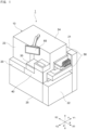
- FIG. 1 is a perspective view of an outer appearance of a specimen measurement apparatus 1 according to the present embodiment.
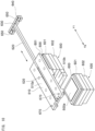
- FIG. 2 illustrates an example of an internal configuration of the specimen measurement apparatus 1.
- the specimen measurement apparatus 1 is a specimen analyzer for measuring and analyzing a specimen with use of a reagent.
- the specimen measurement apparatus 1 has an almost rectangular-parallelepiped-shaped housing (apparatus housing) 10.
- the housing 10 has a front surface portion 20, a rear surface portion 21, a right side surface portion 22, a left side surface portion 23, an upper surface portion 24, and a bottom surface portion 25.
- "left" and "right” of the specimen measurement apparatus 1 are based on directions defined by viewing the front surface portion 20 from the front surface side.
- the front-rear direction of the specimen measurement apparatus 1 is also referred to as Y direction (the rear direction is Y1 direction, the front direction is Y2 direction), the left-right direction thereof is also referred to as X direction (the right direction is X1 direction, the left direction is X2 direction), and the up-down direction thereof is also referred to as Z direction.
- the front surface portion 20 has a plurality of openable/closable portions for allowing access to an internal space of the housing 10.
- the front surface portion 20 has an openable/closable portion 30 through which a reagent container is put in and taken out from a reagent container storage portion 140 described below.
- the front surface portion 20 has a front cover 40 through which the reagent container storage portion 140 is accessed from the front surface side at the time of maintenance.
- the front cover 40 is detachably attached to the housing 10 through bolts, screws, and the like.
- the reagent container storage portion 140 and a holder 510 described below are disposed near the front cover 40 in, for example, a range of 1 mm or less therefrom.
- the right side surface portion 22 and the rear surface portion 21 have a specimen transport unit 50 for transporting a specimen container held by a specimen rack.
- a specimen container transported into the right side surface portion 22 is transported from the right side surface portion 22 to the rear surface portion 21 by the specimen transport unit 50.
- the upper surface portion 24 has a monitor 60 as a display unit.
- the monitor 60 is a touch-panel-type display. Information for an operation required for measuring a specimen can be inputted to the monitor 60, and various information and information of specimen measurement results can be displayed on the monitor 60.
- the specimen measurement apparatus 1 includes, inside the housing 10, a specimen dispensing portion 100, a container transfer portion 110, a container supply portion 120, a reagent dispensing portion 130 (130a to 130e), the reagent container storage portion 140, a reaction portion 150, a BF separation portion 160, and a measurement unit 170.
- the specimen dispensing portion 100 can suction a specimen from a specimen container 200 transported to a specimen suctioning position P1 by the specimen transport unit 50, and dispense the suctioned specimen into a reaction container 210 positioned at a specimen dispensing position P2.
- the specimen dispensing portion 100 is disposed near the end portion, on the rear surface side (Y1 direction side), of the housing 10 and near the end portion on the left side (X2 direction side).
- the specimen dispensing portion 100 has a nozzle 100a for performing suctioning and dispensing, and a nozzle moving mechanism 100b for moving the nozzle 100a.
- the nozzle moving mechanism 100b can perform an operation of rotating the nozzle 100a around a rotation shaft 100c and an operation of moving the nozzle 100a in the up-down direction.
- the specimen dispensing portion 100 can move the nozzle 100a to the specimen suctioning position P1 on a transport path 51 of the specimen transport unit 50 and the specimen dispensing position P2 by rotation around the rotation shaft 100c.
- the specimen dispensing portion 100 can move the nozzle 100a into the specimen container 200 positioned at the specimen suctioning position P1 and can move the nozzle 100a outward from the specimen container 200 by moving the nozzle 100a in the up-down direction.
- the specimen dispensing portion 100 can move the nozzle 100a into the reaction container 210 positioned at the specimen dispensing position P2 and can move the nozzle 100a outward from the reaction container 210 by moving the nozzle 100a in the up-down direction.
- the container transfer portion 110 can transfer the reaction container 210 in the housing 10.
- the container transfer portion 110 can take an empty reaction container 210 from the container supply portion 120, and transfer the reaction container 210 to positions at which the specimen dispensing portion 100, the reagent dispensing portion 130 (130a to 130e), the reaction portion 150, the BF separation portion 160, and the measurement unit 170 perform processing.
- the container transfer portion 110 has a catcher 110a for holding the reaction container 210, and a moving mechanism for moving the catcher 110a.
- the moving mechanism may be an orthogonal robot that is movable in three orthogonal axis directions including the up-down direction, the left-right direction, and the front-rear direction.
- the moving mechanism may include an arm mechanism that horizontally rotates around a rotation shaft, and a multi-joint robot mechanism.
- a plurality of unused reaction containers 210 can be stored in the container supply portion 120.
- the container supply portion 120 can supply an unused empty reaction container 210 to the container transfer portion 110 at a predetermined container supply position P3.
- the reagent dispensing portion 130 can suction reagents in reagent containers 220 to 222, and dispense the suctioned reagents into the reaction container 210.
- the reagent dispensing portion 130 includes a first reagent dispensing portion 130a for dispensing an R1 reagent in the reagent container 220, a second reagent dispensing portion 130b for dispensing an R2 reagent in the reagent container 221, and a third reagent dispensing portion 130c for dispensing an R3 reagent in the reagent container 222.
- the reagent dispensing portion 130 further includes a fourth reagent dispensing portion 130d for dispensing an R4 reagent and a fifth reagent dispensing portion 130e for dispensing an R5 reagent.
- the reagent containers 220, 221, 222 are stored in the reagent container storage portion 140.
- the first reagent dispensing portion 130a has a nozzle 250 for suctioning and dispensing the R1 reagent.
- the first reagent dispensing portion 130a can move the nozzle 250 to a suctioning position P4a at which the R1 reagent in the reagent container 220 is suctioned, and an R1 reagent dispensing position P4b at which the R1 reagent is dispensed into the reaction container 210.
- the second reagent dispensing portion 130b has a nozzle 260 for suctioning and dispensing the R2 reagent.
- the second reagent dispensing portion 130b can move the nozzle 260 to a suctioning position P5a at which the R2 reagent in the reagent container 221 is suctioned, and an R2 reagent dispensing position P5b at which the R2 reagent is dispensed into the reaction container 210.
- the third reagent dispensing portion 130c has a nozzle 270 for suctioning and dispensing the R3 reagent.
- the third reagent dispensing portion 130c can move the nozzle 270 to a suctioning position P6a at which the R3 reagent in the reagent container 222 is suctioned, and an R3 reagent dispensing position P6b at which the R3 reagent is dispensed into the reaction container 210.
- the fourth reagent dispensing portion 130d and the fifth reagent dispensing portion 130e are disposed at positions different from the positions in the reagent container storage portion 140.
- the fourth reagent dispensing portion 130d and the fifth reagent dispensing portion 130e are connected through liquid sending tubes to reagent containers for storing the R4 reagent and the R5 reagent, respectively, and can dispense the reagents into the reaction container 210 transferred by the container transfer portion 110.
- the reagent containers in which the R4 reagent and the R5 reagent are stored may be disposed near the front surface portion 20 of the housing 10.
- the reagent container storage portion 140 can store the reagent containers 220, 221, 222 for the R1 to R3 reagents.
- the reagent container storage portion 140 is disposed near the front surface portion 20 of the housing 10. The configuration of the reagent container storage portion 140 will be described below in detail.
- the reaction portion 150 includes a heater and a temperature sensor, and can hold the reaction container 210 and heat a sample (specimen and reagent) stored in the reaction container 210 to cause a reaction.
- the BF separation portion 160 can perform a BF separation process for separating the sample in the reaction container 210.
- the BF separation portion 160 can suction a liquid component in the reaction container 210 by a suction tube in a state where complexes including magnetic particles are collected by a magnetic force.
- the BF separation portion 160 can separate and remove, from the complexes, unnecessary substances which are contained in the liquid component and are not bound to magnetic particles in the reaction container 210.
- the measurement unit 170 can optically measure the sample in the reaction container 210.
- the measurement unit 170 can detect, by a photodetector, light generated during reaction between a labeled antibody (labeled substance) bound to an antigen of the specimen, and a chemiluminescent substrate, and output measurement data based on a detected light amount.
- the photodetector may include a photomultiplier.
- the reagent container storage portion 140 includes a heat-insulating case 300, a container holding portion 301 for holding the reagent containers 220 to 222 in the case 300, and a fan 302.
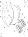
- FIG. 3 illustrates an outer appearance of the reagent container storage portion 140.
- FIG. 4 and FIG. 5 illustrate an internal configuration of the reagent container storage portion 140.
- the case 300 has an almost columnar outer appearance.
- the case 300 has a cylindrical circumferential side portion 310, a disk-shaped upper portion 311, and a disk-shaped bottom portion 312.
- the case 300 may have a heat insulating material that covers a part or the entirety of the outer surface.
- the upper portion 311 has the openable/closable portion 30 through which the reagent containers 220 to 222 are put and taken out.
- the upper portion 311 has holes 330 formed at positions corresponding to the suctioning positions P4a, P5a, and P6a for the nozzles 250, 260, and 270 of the reagent dispensing portion 130.
- the holes 330 are openable and closable.
- the nozzles 250, 260, and 270 of the reagent dispensing portion 130 can be moved into the case 300 through the holes 330, and can suction reagents in the reagent containers.
- the bottom portion 312 has a bottom plate 340 having high thermal conductivity.
- the bottom plate 340 is disk-shaped, and has, at its center, a hole 350 into which rotation shafts 450, 460 described below are inserted.
- the bottom plate 340 may be formed of a metal such as aluminum.
- the bottom plate 340 is exposed to the internal space of the case 300, and the upper surface of the bottom plate 340 forms the bottom of the internal space.
- the outer side portion of the bottom plate 340 in the bottom portion 312 may be covered with a heat insulating material.
- the circumferential side portion 310 has a plurality of supports 360 erected in the up-down direction.
- the plurality of supports 360 are equally spaced on the same circumference along the circumferential direction.
- the support 360 is erected on the upper surface of the bottom plate 340.
- a portion around the support 360 in the circumferential side portion 310 is covered with a heat insulating material.
- the container holding portion 301 has a first holding member 400 and a first rotation mechanism 401 for rotating the first holding member 400, and a second holding member 410 and a second rotation mechanism 411 for rotating the second holding member 410.
- the first holding member 400 is formed into an annular shape, and can hold a plurality of reagent containers aligned in the circumferential direction.
- the first holding member 400 can concentrically hold the reagent containers so as to form two circles.
- the first holding member 400 can hold the reagent containers 222 on the inner circumferential side, and can hold the reagent containers 220 on the outer circumferential side.
- the reagent containers 222 and the reagent containers 220 may be integrated with each other.
- the first rotation mechanism 401 has the rotation shaft 450 connected to the first holding member 400 and a motor 452 that rotates the rotation shaft 450 through a belt 451.
- the rotation shaft 450 is disposed on a center axis C1 of the case 300 along the up-down direction.
- the rotation shaft 450 penetrates through the hole 350 of the bottom plate 340, and extends downward of the bottom portion 312.
- the motor 452 is fixed to the lower surface of the bottom portion 312.
- the belt 451 connects between the rotation shaft 450 and the motor 452 below the bottom portion 312.
- the first holding member 400 can be rotated around the center axis C1 by the first rotation mechanism 401, and a predetermined reagent container 222, 220 held by the first holding member 400 can be moved to a position immediately below the suctioning position P4a, P6a (hole 330).
- the second holding member 410 is formed in an annular shape, and can hold a plurality of the reagent containers 221 aligned in the circumferential direction.
- the second holding member 410 is disposed on the circumference outward of the first holding member 400.
- the second rotation mechanism 411 has the rotation shaft 460 connected to the second holding member 410, and a motor 462 that rotates the rotation shaft 460 through a belt 461.
- the rotation shaft 460 is disposed on the center axis C1 of the case 300 along the up-down direction.
- the rotation shaft 460 is formed in a tubular shape, and disposed on the circumference outward of the rotation shaft 450.
- the rotation shaft 460 penetrates through the hole 350 of the bottom plate 340, and extends downward of the bottom portion 312.
- the motor 462 is fixed to the lower surface of the bottom portion 312.
- the belt 461 connects between the rotation shaft 460 and the motor 462 below the bottom portion 312.
- the second holding member 410 can be rotated around the center axis C1 by the second rotation mechanism 411, and a predetermined reagent container 221 held by the second holding member 410 can be moved to a position immediately below the suctioning position P5a (hole 330).
- the fan 302 is disposed in an internal space of the case 300.
- the fan 302 is disposed on the center axis C1 of the case 300.
- the fan 302 is disposed near the center of the internal space of the case 300 in the up-down direction.
- the fan 302 is oriented downward, and can send air toward the bottom plate 340.
- the specimen measurement apparatus 1 has a cooling mechanism for cooling and maintaining a reagent in the reagent container in the reagent container storage portion 140 at a predetermined temperature.
- FIG. 6 is a perspective view of a configuration of the cooling mechanism disposed at the bottom portion 312 of the reagent container storage portion 140.
- FIG. 7 is a partial cross-sectional view of the configuration of the cooling mechanism of the reagent container storage portion 140.
- the specimen measurement apparatus 1 has a cooling unit 500 for cooling a predetermined portion of the reagent container storage portion 140, and the holder 510 that holds the cooling unit 500, is in contact with a portion of the reagent container storage portion 140, and is slidable relative to the portion.
- the holder 510 has a lower surface (holding surface) 510b for holding the cooling unit 500 in a state where the lower surface 510b is in contact with the cooling surface 500a, and an upper surface (contact surface) 510a that is in contact with the bottom plate 340 of the reagent container storage portion 140. That is, the cooling unit 500 can cool the bottom plate 340 of the reagent container storage portion 140 through the holder 510.
- a metal such as aluminum, having high thermal conductivity is used.
- the holding surface 510b and the contact surface 510a of the holder 510 may be flat surfaces.
- the cooling surface 500a of the Peltier device 600, the holding surface 510b and the contact surface 510a of the holder 510, and a cooling surface (lower surface) of the bottom plate 340 are flat surfaces and are in close contact with each other. Therefore, heat of the cooling unit 500 can be efficiently transmitted to the bottom plate 340.
- the holder 510 can be detachably mounted to the bottom plate 340 of the reagent container storage portion 140.
- the bottom portion 312 of the reagent container storage portion 140 has two rails 620 extending in the Y direction, on both sides in the X direction across the center axis C1.
- the two rails 620 are positioned such that distances from the respective rails 620 to the center axis C1 are equal to each other.
- the rail 620 is disposed in a groove 610 formed at the lower surface of the bottom portion 312 of the reagent container storage portion 140 so as to extend in the Y direction.
- a groove 520 is formed at the center of the upper surface 510a of the holder 510 so as to extend in the Y direction, and the rail 620 fits in the groove 520.
- the holder 510 can be moved along the rail 620 in the Y direction. That is, the holder 510 functions as a slider, and the two cooling units 500 can be moved from the cooling positions P10 in the Y direction.
- the holder 510 can be moved along the rail 620 to the outside of the bottom portion 312 (the circumferential side portion 310). Furthermore, as illustrated in FIG. 2 , the holder 510 can be moved along the rail 620 to the outside of the housing 10. The holder 510 may be moved to the outside of the housing 10 by removing the front cover 40 of the housing 10.
- the holder 510 is further moved onto an extension of the rail 620 and is thus dismounted from the rail 620.
- both the holder 510 and the cooling unit 500 can be dismounted from the bottom plate 340 (the bottom portion 312) of the reagent container storage portion 140.
- the cooling unit 500 can be mounted to the bottom plate 340 (the bottom portion 312) of the reagent container storage portion 140.
- the bottom portion 312 of the reagent container storage portion 140 has a stopper 630 for stopping movement of the holder 510 when the cooling unit 500 has been moved to the cooling position P10.
- the specimen measurement apparatus 1 has a pressing portion 640 for pressing the holder 510 against the bottom plate 340 when the cooling unit 500 has been moved to the cooling position P10.
- the pressing portion 640 has an inclined lower surface 651 which is disposed at the end portion of the holder 510 in the Y1 direction and is inclined so as to gradually ascend toward the end, and an inclined upper surface 650 which is disposed so as to oppose the end portion of the holder 510 and is inclined so as to gradually descend toward the end in the Y2 direction.
- the inclined upper surface 650 may be disposed at the stopper 630. As illustrated in FIG.
- the specimen measurement apparatus 1 may have a retaining member (fastening member) 670 such as a bolt for fastening the holder 510 to the bottom portion 312 (the bottom plate 340) in a state where the cooling unit 500 is positioned at the cooling position P10.
- the retaining member 670 is disposed at the rear end portion of the holder 510 in the Y2 direction.
- a portion around the holder 510 may be covered by a heat insulating cover 680 forming a part of the bottom portion 312.
- the holder 510 may be moved together with the heat insulating cover 680.
- a handle 681 for drawing the holder 510 may be formed in the heat insulating cover 680.
- the cooling unit 500 may be detachably mounted to the holder 510.
- the cooling unit 500 may be dismounted from the holder 510 by using a fastening member such as a bolt.
- FIG. 13 illustrates an example of a configuration of a control unit of the specimen measurement apparatus 1.
- the specimen measurement apparatus 1 includes a main control unit 700 and a measurement control unit 701.
- the main control unit 700 includes a controller 710, a communication unit 711, and a storage unit 712.
- the controller 710 includes a processor implemented by a CPU or a FPGA, and a memory, and can control each of the components of the specimen measurement apparatus 1 by executing a program stored in the storage unit 712.
- the storage unit 712 is implemented by a semiconductor storage element, and can store the program to be executed by the controller 710, measurement information obtained by the measurement unit 170, and the like.
- the communication unit 711 includes an I/O interface and a communication interface for communicating with an analyzer 800 and the measurement control unit 701.
- the measurement control unit 701 has a communication circuit for communicating with each of the components of the specimen measurement apparatus 1 and the main control unit 700.
- the measurement control unit 701 can control operations of the specimen dispensing portion 100, the container transfer portion 110, the container supply portion 120, the reagent dispensing portion 130 (130a to 130e), the reagent container storage portion 140, the reaction portion 150, the BF separation portion 160, and the measurement unit 170 according to instructions from the controller 710 of the main control unit 700.
- the measurement control unit 701 can output measurement information obtained by the measurement unit 170 in a specimen measurement process, to the main control unit 700.
- the analyzer 800 is implemented by a personal computer (PC), and may mainly include a main body including a CPU, a ROM, a RAM, a solid state drive (SSD), and the like, a display unit including a liquid crystal display, and an input device including a keyboard and a mouse.
- PC personal computer
- main body including a CPU, a ROM, a RAM, a solid state drive (SSD), and the like
- SSD solid state drive
- display unit including a liquid crystal display
- an input device including a keyboard and a mouse.
- the analyzer 800 is connected to the communication unit 711 of the main control unit 700 and a host computer 900 so as to be able to communicate therewith.
- the controller 710 can operate to transmit the measurement information obtained by measuring a specimen by the measurement unit 170, through the communication unit 711, to the analyzer 800.
- the analyzer 800 can analyze, for example, a content of a test substance in a specimen based on the obtained measurement information. Furthermore, the analyzer 800 can display an analysis result on a display screen of a display unit (monitor 60) and transmit the analysis result to the host computer 900.
- the specimen measurement process is performed by the main control unit 700 and the measurement control unit 701.
- the specimen measurement process includes, for example, immunoassay.
- immunoassay an example in which a test substance contained in a specimen is hepatitis B surface antigen (HBsAg) will be described.
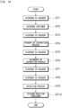
- FIG. 14 is a flow chart showing an example of the immunoassay.
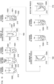
- FIG. 15 illustrates the immunoassay.
- step ST1 shown in FIG. 14 the R1 reagent is dispensed into the reaction container 210.
- the reaction container 210 is transferred to the R1 reagent dispensing position P4b by the container transfer portion 110 illustrated in FIG. 2 .
- the R1 reagent in the reagent container 220 is suctioned at the suctioning position P4a of the reagent container storage portion 140 by the nozzle 250 of the first reagent dispensing portion 130a, and the R1 reagent is dispensed into the reaction container 210 at the R1 reagent dispensing position P4b.
- the R1 reagent contains a capture substance 1000.
- the capture substance 1000 may be an antibody (biotin antibody) modified with biotin.
- step ST2 shown in FIG. 14 the specimen is dispensed into the reaction container 210.
- the reaction container 210 is transferred to the specimen dispensing position P2 by the container transfer portion 110 illustrated in FIG. 2 .
- the specimen in the specimen container 200 is suctioned at the specimen suctioning position P1 by the nozzle 100a of the specimen dispensing portion 100, and the specimen is dispensed into the reaction container 210 at the specimen dispensing position P2.
- the specimen contains a test substance 1001.
- the test substance 1001 contained in the specimen reacts with and binds to the capture substance 1000.
- step ST3 shown in FIG. 14 the R2 reagent is dispensed into the reaction container 210.
- the reaction container 210 is transferred to the R2 reagent dispensing position P5b by the container transfer portion 110 illustrated in FIG. 2 .
- the R2 reagent in the reagent container 221 is suctioned at the suctioning position P5a of the reagent container storage portion 140 by the nozzle 260 of the second reagent dispensing portion 130b, and the R2 reagent is dispensed into the reaction container 210 at the R2 reagent dispensing position P5b.
- the reaction container 210 is transferred to the reaction portion 150 by the container transfer portion 110, and the reaction container 210 is heated in the reaction portion 150 for a predetermined time period.
- the R2 reagent contains magnetic particles (solid-phase carrier) 1002 that bind to the capture substance 1000.
- the magnetic particles 1002 may be magnetic particles (StAvi-bound magnetic particles) having immobilized thereon streptavidin which binds to biotin.
- the test substance 1001 and the capture substance 1000 bind to the magnetic particle 1002.
- a primary BF separation process is performed.
- the reaction container 210 is transferred to the BF separation portion 160 by the container transfer portion 110 illustrated in FIG. 2 .
- the primary BF separation process is performed for the sample in the reaction container 210.
- unnecessary components such as the unreacted capture substance 1000 which does not bind to the magnetic particles 1002 are removed from the reaction container 210.
- step ST5 shown in FIG. 14 the R3 reagent is dispensed into the reaction container 210.
- the reaction container 210 is transferred to the R3 reagent dispensing position P6b by the container transfer portion 110 illustrated in FIG. 2 .
- the R3 reagent in the reagent container 222 is suctioned at the suctioning position P6a of the reagent container storage portion 140 by the nozzle 270 of the third reagent dispensing portion 130c, and the R3 reagent is dispensed into the reaction container 210 at the R3 reagent dispensing position P6b.
- the reaction container 210 is transferred to the reaction portion 150 by the container transfer portion 110, and the reaction container 210 is heated in the reaction portion 150 for a predetermined time period.
- the R3 reagent contains a labeled substance 1003.
- the labeled substance 1003 may be an ALP (alkaline phosphatase) labeled antibody.
- the labeled substance 1003 reacts with and binds to the test substance 1001.
- An immune complex 1004 containing the test substance 1001, the labeled substance 1003, and the capture substance 1000 is formed on the magnetic particle 1002.
- a secondary BF separation process is performed.
- the reaction container 210 is transferred to the BF separation portion 160 by the container transfer portion 110 illustrated in FIG. 2 .
- the secondary BF separation process is performed for the sample in the reaction container 210.
- unnecessary components such as the unreacted labeled substance 1003 which does not bind to the magnetic particles 1002 are removed from the reaction container 210.
- step ST7 shown in FIG. 14 the R4 reagent is dispensed into the reaction container 210.
- the reaction container 210 is transferred to the fourth reagent dispensing portion 130d by the container transfer portion 110 illustrated in FIG. 2 , and the R4 reagent is dispensed into the reaction container 210 by the fourth reagent dispensing portion 130d.
- the R4 reagent contains a buffer.
- the immune complex 1004 that binds to the magnetic particles 1002 in the reaction container 210 is dispersed in the buffer.
- step ST8 shown in FIG. 14 the R5 reagent is dispensed into the reaction container 210.
- the reaction container 210 is transferred to the fifth reagent dispensing portion 130e by the container transfer portion 110 illustrated in FIG. 2 , and the R5 reagent is dispensed into the reaction container 210 by the fifth reagent dispensing portion 130e.
- the reaction container 210 is transferred to the reaction portion 150 by the container transfer portion 110, and the reaction container 210 is heated in the reaction portion 150 for a predetermined time period.
- the R5 reagent contains a chemiluminescent substrate. As illustrated in FIG.
- the buffer contained in the R4 reagent has a composition that promotes reaction between a label (enzyme) of the labeled substance 1003 contained in the immune complex 1004, and the chemiluminescent substrate. Light is generated by reacting the substrate with the label through heating.
- step ST9 shown in FIG. 14 a process of detecting the immune complex 1004 is performed.
- the reaction container 210 is transferred to the measurement unit 170 by the container transfer portion 110 illustrated in FIG. 2 .
- an intensity of light generated by reacting the substrate with the label is measured by the measurement unit 170.
- the measurement data obtained by the measurement unit 170 is transmitted to the analyzer 800 through the measurement control unit 701 and the main control unit 700, and, for example, a content of the test substance in the specimen is measured by the analyzer 800.
- step ST10 shown in FIG. 14 the reaction container 210 is taken out from the measurement unit 170 by the container transfer portion 110, and discarded into a disposal outlet.
- the front cover 40 disposed at the front surface portion 20 of the housing 10 is firstly removed, the heat insulating cover 680 is subsequently removed, and fixing of the holder 510 and the bottom plate 340 to each other by the exposed retaining member 670 is released. Thereafter, the holder 510 is drawn. Specifically, the holder 510 is moved along the rail 620 in the Y2 direction, and is removed from the rail 620. Thus, the cooling unit 500 is removed from the bottom plate 340 of the reagent container storage portion 140 by the holder 510. Thereafter, the cooling unit 500 may be removed from the holder 510.
- the holder 510 holding a new cooling unit 500 is mounted to the rail 620, and moved along the rail 620 in the Y1 direction.
- the cooling unit 500 has been moved to the cooling position P10
- the holder 510 is stopped by the stopper 630, and pressed against the bottom plate 340 by the pressing portion 640.
- the holder 510 and the bottom plate 340 are fixed by the retaining member 670.
- the front cover 40 is attached to the front surface portion 20 of the housing 10.
- the specimen measurement apparatus 1 includes the holder 510 that is slidably mounted to the reagent container storage portion 140 in a state where the holder 510 holds the cooling unit 500. Therefore, the position of the cooling unit 500 relative to the reagent container storage portion 140 can be shifted to a position suitable for the operation, so that the cooling unit 500 can be easily dismounted from and mounted to the reagent container storage portion 140.
- the specimen measurement apparatus 1 includes the holder 510 having the holding surface 510b for holding the cooling unit 500 in a state where the holding surface 510b is in contact with the cooling surface 500a, and the contact surface 510a that comes into contact with the bottom plate 340 of the reagent container storage portion 140.
- heat transmission between the cooling unit 500 and the bottom plate 340 can be efficiently performed.
- the cooling unit 500 is replaced, attention need not be paid in order to prevent air from entering between the cooling unit 500 and the bottom plate 340, and a screw or a bolt for fixing the cooling unit 500 to the bottom plate 340 need not be carefully fastened in order to prevent damage to the Peltier device, and thus, the cooling unit 500 can be easily replaced.
- the holder 510 is configured to be movable along the bottom plate 340 in the horizontal direction. Therefore, the holder 510 holding the cooling unit 500 can be drawn from the outer portion, in the horizontal direction, of the reagent container storage portion 140. Thus, the cooling unit 500 can be easily dismounted and mounted.
- the specimen measurement apparatus 1 further includes the rail 620 disposed along the horizontal direction at the bottom plate 340, and the holder 510 is movable along the rail 620. Therefore, the holder 510 can be suitably moved in the horizontal direction.
- the rail 620 is disposed in the groove 610 formed in the bottom portion 312. Therefore, the holder 510 can efficiently transmit heat between the cooling unit 500 and the bottom plate 340.
- the holder 510 is configured to be in surface contact with the bottom plate 340 in a state where the holder 510 is mounted to the rail 620. Therefore, the holder 510 can efficiently transmit heat between the cooling unit 500 and the bottom plate 340.
- the holder 510 holds a plurality of the cooling units 500. Therefore, the plurality of the cooling units 500 can be efficiently dismounted and mounted.
- the specimen measurement apparatus 1 includes a plurality of the rails 620 and a plurality of the holders 510 that move on the rails 620, respectively. Therefore, the plurality of the cooling units 500 can be efficiently dismounted and mounted.
- the holder 510 can be detachably mounted to the rail 620. Therefore, by the holder 510 being dismounted from or mounted to the rail 620, the cooling unit 500 can be easily dismounted or mounted.
- the holder 510 By moving the holder 510 onto an extension of the rail 620, the holder 510 is dismounted from the rail 620. Therefore, the holder 510 can be suitably mounted to and dismounted from the rail 620.
- the specimen measurement apparatus 1 includes the stopper 630 for stopping movement of the holder 510 when the cooling unit 500 has been moved to the predetermined cooling position P10. Therefore, the position of the cooling unit 500 can be appropriately adjusted with ease.
- the specimen measurement apparatus 1 includes the pressing portion 640 for pressing the holder 510 against the bottom plate 340 when the cooling unit 500 has been moved to the predetermined cooling position P10. Therefore, adhesion between the holder 510 and the bottom plate 340 is enhanced, and the holder 510 can efficiently transmit heat between the cooling unit 500 and the bottom plate 340.
- the pressing portion 640 has the inclined lower surface 651 and the inclined upper surface 650, and the inclined lower surface 651 and the inclined upper surface 650 fit to each other when the cooling unit 500 has been moved to the cooling position P10.
- the holder 510 can be suitably pressed against the bottom plate 340.
- the specimen measurement apparatus 1 includes the retaining member 670 for retaining the holder 510 to the bottom plate 340 in a state where the cooling unit 500 is positioned at the predetermined cooling position P10. Therefore, the holder 510 can be fixed (position-fixed) to the bottom plate 340.
- the retaining member 670 is disposed at an end portion near the outer side of the bottom plate 340 in the holder 510. Therefore, an operator is allowed to easily access the retaining member 670 from the outside of the reagent container storage portion 140.
- the holder 510 can be moved along the rail 620 to the outside of the bottom plate 340. Therefore, the operator is allowed to easily dismount and mount the cooling unit 500.
- the holder 510 can be moved along the rail 620 to the outside of the apparatus housing 10 of the specimen measurement apparatus 1. Therefore, the operator is allowed to easily dismount and mount the cooling unit 500.
- the cooling unit 500 can be detachably mounted to the holder 510. Therefore, for example, the cooling unit 500 is dismounted from the holder 510 and can be replaced with a new cooling unit 500.
- the specimen measurement apparatus 1 may further include a connection member 1100 for connecting the plurality of the holders 510 to each other.
- the plurality of the holders 510 can be integrally moved.
- the number of the cooling units 500 held by the holder 510 is not limited to two, and may be one, or three or more. Furthermore, the number of the holders 510 is not limited to two, and may be one, or three or more. In a case where the number of the holders 510 is plural, the number of the cooling units 500 held by the holder 510 may be different among the holders 510.
- the portion to be cooled in the reagent container storage portion 140 is not limited to the bottom portion 312 (the bottom plate 340), and another portion may be cooled.
- the configuration of the reagent container storage portion which is cooled by the cooling unit is not limited to that of the above-described embodiment.
- the reagent container storage portion cooled by the cooling unit may store reagent containers of other reagents such as the R4 reagent and the R5 reagent other than the R1 reagent, the R2 reagent, and the R3 reagent.
- the holder 510 is moved in the horizontal direction, and is thus dismounted from the bottom plate 340 of the reagent container storage portion 140.
- the direction in which the holder 510 is moved is not limited to the horizontal direction.
- the holder 510 may be moved in the up-down direction, and thus dismounted from the bottom plate 340 of the reagent container storage portion 140.
- the specimen measurement apparatus performs immunoassay.
- the present invention can also be applied to a specimen measurement apparatus that performs another specimen measurement as long as the specimen measurement apparatus measures a specimen by using a reagent.
- the present disclosure includes the following items 1-23.
Landscapes
- Physics & Mathematics (AREA)
- Health & Medical Sciences (AREA)
- Life Sciences & Earth Sciences (AREA)
- Chemical & Material Sciences (AREA)
- Analytical Chemistry (AREA)
- Biochemistry (AREA)
- General Health & Medical Sciences (AREA)
- General Physics & Mathematics (AREA)
- Immunology (AREA)
- Pathology (AREA)
- Automatic Analysis And Handling Materials Therefor (AREA)
- Devices For Use In Laboratory Experiments (AREA)
Abstract
Description
- This application claims priority from prior
Japanese Patent Application No. 2023-057050, filed on March 31, 2023 - The present invention relates to a specimen measurement apparatus and a maintenance method.
- A specimen measurement apparatus includes a reagent container storage portion in which a plurality of reagent containers are stored. For example, the device disclosed in
Japanese Laid-Open Patent Publication No. H2-184345 - The cooling unit such as the above-described electronic cooling means may deteriorate or malfunction when the cooling unit has been used for a long time period. In such a case, the cooling unit may be replaced. However, for the device disclosed in
Japanese Laid-Open Patent Publication No. H2-184345 - The present invention has been made in view of such circumstances, and an object of the present invention is to provide a specimen measurement apparatus and a maintenance method for the specimen measurement apparatus in which a cooling unit for cooling a reagent container storage portion can be easily dismounted and mounted.
- As illustrated in
FIG. 2 , andFIG. 6 toFIG. 12 , a specimen measurement apparatus of the present invention includes: a measurement unit (170) configured to measure a specimen by using a reagent; a reagent container storage portion (140) configured to store a reagent container (220 to 222) in which the reagent is stored; a cooling unit (500) configured to cool the reagent container storage portion (140); and a holder (510) slidably mounted to the reagent container storage portion (140) in a state where the holder (510) holds the cooling unit (500). - In the specimen measurement apparatus of the present invention, the holder (510) can be slid relative to the reagent container storage portion (140) in a state where the holder (510) holds the cooling unit (500). Therefore, a position of the cooling unit (500) relative to the reagent container storage portion (140) can be shifted to a position suitable for the operation.
As a result, the cooling unit (500) can be easily dismounted and mounted. - As illustrated in
FIG. 2 , andFIG. 6 toFIG. 12 , a maintenance method of the present invention is directed to a maintenance method for performing maintenance of a specimen measurement apparatus (1) including: a measurement unit (170) configured to measure a specimen by using a reagent; a reagent container storage portion (140) configured to store a reagent container (220 to 222) in which the reagent is stored; a cooling unit (500) configured to cool the reagent container storage portion (140); and a holder (510) slidably mounted to the reagent container storage portion (140) in a state where the holder (510) holds the cooling unit (500). The maintenance method includes: dismounting the holder holding the cooling unit (500) from the reagent container storage portion (140); and mounting the holder (510) holding a new cooling unit (500) or a new holder (510) holding a new cooling unit (500) to the reagent container storage portion (140). - In the maintenance method of the present invention, the holder (510) slidably mounted to the reagent container storage portion (140) in a state where the holder (510) holds the cooling unit (500) is dismounted from and mounted to the reagent container storage portion (140). Therefore, the cooling unit (500) can be easily dismounted from and mounted to the reagent container storage portion (140).
- According to the present invention, the cooling unit for cooling the reagent container storage portion can be easily dismounted and mounted.
-
-
FIG. 1 is a perspective view of an outer appearance of a specimen measurement apparatus according to an embodiment; -
FIG. 2 illustrates an example of an internal configuration of the specimen measurement apparatus; -
FIG. 3 illustrates an outer appearance of a reagent container storage portion; -
FIG. 4 illustrates an internal configuration of the reagent container storage portion; -
FIG. 5 illustrates an internal configuration of the reagent container storage portion; -
FIG. 6 is a perspective view of a configuration of a cooling mechanism disposed at a bottom portion of the reagent container storage portion; -
FIG. 7 is a partial cross-sectional view of the configuration of the cooling mechanism of the reagent container storage portion; -
FIG. 8 is a perspective view of a holder for holding a cooling unit; -
FIG. 9 illustrates a mechanism for moving the holder at the reagent container storage portion; -
FIG. 10 illustrates the mechanism for moving the holder; -
FIG. 11 illustrates a state where the holder is moved; -
FIG. 12 illustrates a state where the holder has been dismounted from the reagent container storage portion; -
FIG. 13 illustrates an example of a configuration of a control unit of the specimen measurement apparatus; -
FIG. 14 is a flow chart showing an example of main process steps of immunoassay; -
FIG. 15 illustrates an example of the immunoassay; and -
FIG. 16 illustrates a connection member for connecting a plurality of the holders to each other. - A specimen measurement apparatus and a maintenance method for the specimen measurement apparatus according to an exemplary embodiment of the present disclosure will be described below in detail with reference to the drawings.
-
FIG. 1 is a perspective view of an outer appearance of aspecimen measurement apparatus 1 according to the present embodiment.FIG. 2 illustrates an example of an internal configuration of thespecimen measurement apparatus 1. In one example, thespecimen measurement apparatus 1 is a specimen analyzer for measuring and analyzing a specimen with use of a reagent. - As shown in
FIG. 1 , thespecimen measurement apparatus 1 has an almost rectangular-parallelepiped-shaped housing (apparatus housing) 10. Thehousing 10 has afront surface portion 20, arear surface portion 21, a rightside surface portion 22, a leftside surface portion 23, anupper surface portion 24, and abottom surface portion 25. In the present specification, "left" and "right" of thespecimen measurement apparatus 1 are based on directions defined by viewing thefront surface portion 20 from the front surface side. In the present specification, the front-rear direction of thespecimen measurement apparatus 1 is also referred to as Y direction (the rear direction is Y1 direction, the front direction is Y2 direction), the left-right direction thereof is also referred to as X direction (the right direction is X1 direction, the left direction is X2 direction), and the up-down direction thereof is also referred to as Z direction. - The
front surface portion 20 has a plurality of openable/closable portions for allowing access to an internal space of thehousing 10. For example, thefront surface portion 20 has an openable/closable portion 30 through which a reagent container is put in and taken out from a reagentcontainer storage portion 140 described below. Thefront surface portion 20 has afront cover 40 through which the reagentcontainer storage portion 140 is accessed from the front surface side at the time of maintenance. Thefront cover 40 is detachably attached to thehousing 10 through bolts, screws, and the like. The reagentcontainer storage portion 140 and aholder 510 described below are disposed near thefront cover 40 in, for example, a range of 1 mm or less therefrom. Thus, theholder 510 can be dismounted from the reagentcontainer storage portion 140 in a state where thefront cover 40 is detached. Thefront cover 40 is disposed on an extension of arail 620, described below, for moving theholder 510. A detachable heat insulating material may be disposed between thefront cover 40 and the reagentcontainer storage portion 140. - The right
side surface portion 22 and therear surface portion 21 have aspecimen transport unit 50 for transporting a specimen container held by a specimen rack. A specimen container transported into the rightside surface portion 22 is transported from the rightside surface portion 22 to therear surface portion 21 by thespecimen transport unit 50. - The
upper surface portion 24 has amonitor 60 as a display unit. Themonitor 60 is a touch-panel-type display. Information for an operation required for measuring a specimen can be inputted to themonitor 60, and various information and information of specimen measurement results can be displayed on themonitor 60. - As illustrated in
FIG. 2 , thespecimen measurement apparatus 1 includes, inside thehousing 10, aspecimen dispensing portion 100, acontainer transfer portion 110, acontainer supply portion 120, a reagent dispensing portion 130 (130a to 130e), the reagentcontainer storage portion 140, areaction portion 150, aBF separation portion 160, and ameasurement unit 170. - The
specimen dispensing portion 100 can suction a specimen from aspecimen container 200 transported to a specimen suctioning position P1 by thespecimen transport unit 50, and dispense the suctioned specimen into areaction container 210 positioned at a specimen dispensing position P2. Thespecimen dispensing portion 100 is disposed near the end portion, on the rear surface side (Y1 direction side), of thehousing 10 and near the end portion on the left side (X2 direction side). - The
specimen dispensing portion 100 has anozzle 100a for performing suctioning and dispensing, and anozzle moving mechanism 100b for moving thenozzle 100a. Thenozzle moving mechanism 100b can perform an operation of rotating thenozzle 100a around arotation shaft 100c and an operation of moving thenozzle 100a in the up-down direction. Thespecimen dispensing portion 100 can move thenozzle 100a to the specimen suctioning position P1 on atransport path 51 of thespecimen transport unit 50 and the specimen dispensing position P2 by rotation around therotation shaft 100c. Thespecimen dispensing portion 100 can move thenozzle 100a into thespecimen container 200 positioned at the specimen suctioning position P1 and can move thenozzle 100a outward from thespecimen container 200 by moving thenozzle 100a in the up-down direction. Thespecimen dispensing portion 100 can move thenozzle 100a into thereaction container 210 positioned at the specimen dispensing position P2 and can move thenozzle 100a outward from thereaction container 210 by moving thenozzle 100a in the up-down direction. - The
container transfer portion 110 can transfer thereaction container 210 in thehousing 10. Thecontainer transfer portion 110 can take anempty reaction container 210 from thecontainer supply portion 120, and transfer thereaction container 210 to positions at which thespecimen dispensing portion 100, the reagent dispensing portion 130 (130a to 130e), thereaction portion 150, theBF separation portion 160, and themeasurement unit 170 perform processing. Thecontainer transfer portion 110 has acatcher 110a for holding thereaction container 210, and a moving mechanism for moving thecatcher 110a. The moving mechanism may be an orthogonal robot that is movable in three orthogonal axis directions including the up-down direction, the left-right direction, and the front-rear direction. The moving mechanism may include an arm mechanism that horizontally rotates around a rotation shaft, and a multi-joint robot mechanism. - In the
container supply portion 120, a plurality ofunused reaction containers 210 can be stored. Thecontainer supply portion 120 can supply an unusedempty reaction container 210 to thecontainer transfer portion 110 at a predetermined container supply position P3. - The
reagent dispensing portion 130 can suction reagents inreagent containers 220 to 222, and dispense the suctioned reagents into thereaction container 210. Thereagent dispensing portion 130 includes a firstreagent dispensing portion 130a for dispensing an R1 reagent in thereagent container 220, a secondreagent dispensing portion 130b for dispensing an R2 reagent in thereagent container 221, and a thirdreagent dispensing portion 130c for dispensing an R3 reagent in thereagent container 222. Thereagent dispensing portion 130 further includes a fourthreagent dispensing portion 130d for dispensing an R4 reagent and a fifthreagent dispensing portion 130e for dispensing an R5 reagent. Thereagent containers container storage portion 140. - The first
reagent dispensing portion 130a has anozzle 250 for suctioning and dispensing the R1 reagent. The firstreagent dispensing portion 130a can move thenozzle 250 to a suctioning position P4a at which the R1 reagent in thereagent container 220 is suctioned, and an R1 reagent dispensing position P4b at which the R1 reagent is dispensed into thereaction container 210. - The second
reagent dispensing portion 130b has anozzle 260 for suctioning and dispensing the R2 reagent. The secondreagent dispensing portion 130b can move thenozzle 260 to a suctioning position P5a at which the R2 reagent in thereagent container 221 is suctioned, and an R2 reagent dispensing position P5b at which the R2 reagent is dispensed into thereaction container 210. - The third
reagent dispensing portion 130c has anozzle 270 for suctioning and dispensing the R3 reagent. The thirdreagent dispensing portion 130c can move thenozzle 270 to a suctioning position P6a at which the R3 reagent in thereagent container 222 is suctioned, and an R3 reagent dispensing position P6b at which the R3 reagent is dispensed into thereaction container 210. - The fourth
reagent dispensing portion 130d and the fifthreagent dispensing portion 130e are disposed at positions different from the positions in the reagentcontainer storage portion 140. The fourthreagent dispensing portion 130d and the fifthreagent dispensing portion 130e are connected through liquid sending tubes to reagent containers for storing the R4 reagent and the R5 reagent, respectively, and can dispense the reagents into thereaction container 210 transferred by thecontainer transfer portion 110. The reagent containers in which the R4 reagent and the R5 reagent are stored may be disposed near thefront surface portion 20 of thehousing 10. - The reagent
container storage portion 140 can store thereagent containers container storage portion 140 is disposed near thefront surface portion 20 of thehousing 10. The configuration of the reagentcontainer storage portion 140 will be described below in detail. - The
reaction portion 150 includes a heater and a temperature sensor, and can hold thereaction container 210 and heat a sample (specimen and reagent) stored in thereaction container 210 to cause a reaction. - The
BF separation portion 160 can perform a BF separation process for separating the sample in thereaction container 210. For example, theBF separation portion 160 can suction a liquid component in thereaction container 210 by a suction tube in a state where complexes including magnetic particles are collected by a magnetic force. Thus, theBF separation portion 160 can separate and remove, from the complexes, unnecessary substances which are contained in the liquid component and are not bound to magnetic particles in thereaction container 210. - The
measurement unit 170 can optically measure the sample in thereaction container 210. For example, themeasurement unit 170 can detect, by a photodetector, light generated during reaction between a labeled antibody (labeled substance) bound to an antigen of the specimen, and a chemiluminescent substrate, and output measurement data based on a detected light amount. The photodetector may include a photomultiplier. - As illustrated in
FIG. 2 , the reagentcontainer storage portion 140 includes a heat-insulatingcase 300, acontainer holding portion 301 for holding thereagent containers 220 to 222 in thecase 300, and afan 302.FIG. 3 illustrates an outer appearance of the reagentcontainer storage portion 140.FIG. 4 andFIG. 5 illustrate an internal configuration of the reagentcontainer storage portion 140. - As illustrated in
FIG. 3 andFIG. 4 , thecase 300 has an almost columnar outer appearance. Thecase 300 has a cylindricalcircumferential side portion 310, a disk-shapedupper portion 311, and a disk-shapedbottom portion 312. Thecase 300 may have a heat insulating material that covers a part or the entirety of the outer surface. - As illustrated in
FIG. 3 , theupper portion 311 has the openable/closable portion 30 through which thereagent containers 220 to 222 are put and taken out. Theupper portion 311 hasholes 330 formed at positions corresponding to the suctioning positions P4a, P5a, and P6a for thenozzles reagent dispensing portion 130. Theholes 330 are openable and closable. Thenozzles reagent dispensing portion 130 can be moved into thecase 300 through theholes 330, and can suction reagents in the reagent containers. - As illustrated in
FIG. 4 , thebottom portion 312 has abottom plate 340 having high thermal conductivity. Thebottom plate 340 is disk-shaped, and has, at its center, ahole 350 into whichrotation shafts bottom plate 340 may be formed of a metal such as aluminum. Thebottom plate 340 is exposed to the internal space of thecase 300, and the upper surface of thebottom plate 340 forms the bottom of the internal space. The outer side portion of thebottom plate 340 in thebottom portion 312 may be covered with a heat insulating material. - The
circumferential side portion 310 has a plurality ofsupports 360 erected in the up-down direction. The plurality ofsupports 360 are equally spaced on the same circumference along the circumferential direction. Thesupport 360 is erected on the upper surface of thebottom plate 340. A portion around thesupport 360 in thecircumferential side portion 310 is covered with a heat insulating material. - The
container holding portion 301 has a first holdingmember 400 and afirst rotation mechanism 401 for rotating the first holdingmember 400, and asecond holding member 410 and asecond rotation mechanism 411 for rotating the second holdingmember 410. - As illustrated in
FIG. 5 , the first holdingmember 400 is formed into an annular shape, and can hold a plurality of reagent containers aligned in the circumferential direction. Thefirst holding member 400 can concentrically hold the reagent containers so as to form two circles. Thefirst holding member 400 can hold thereagent containers 222 on the inner circumferential side, and can hold thereagent containers 220 on the outer circumferential side. Thereagent containers 222 and thereagent containers 220 may be integrated with each other. - As illustrated in
FIG. 4 , thefirst rotation mechanism 401 has therotation shaft 450 connected to the first holdingmember 400 and amotor 452 that rotates therotation shaft 450 through abelt 451. Therotation shaft 450 is disposed on a center axis C1 of thecase 300 along the up-down direction. Therotation shaft 450 penetrates through thehole 350 of thebottom plate 340, and extends downward of thebottom portion 312. Themotor 452 is fixed to the lower surface of thebottom portion 312. Thebelt 451 connects between therotation shaft 450 and themotor 452 below thebottom portion 312. Thefirst holding member 400 can be rotated around the center axis C1 by thefirst rotation mechanism 401, and apredetermined reagent container member 400 can be moved to a position immediately below the suctioning position P4a, P6a (hole 330). - As illustrated in
FIG. 5 , the second holdingmember 410 is formed in an annular shape, and can hold a plurality of thereagent containers 221 aligned in the circumferential direction. Thesecond holding member 410 is disposed on the circumference outward of the first holdingmember 400. - As illustrated in
FIG. 4 , thesecond rotation mechanism 411 has therotation shaft 460 connected to the second holdingmember 410, and amotor 462 that rotates therotation shaft 460 through abelt 461. Therotation shaft 460 is disposed on the center axis C1 of thecase 300 along the up-down direction. Therotation shaft 460 is formed in a tubular shape, and disposed on the circumference outward of therotation shaft 450. Therotation shaft 460 penetrates through thehole 350 of thebottom plate 340, and extends downward of thebottom portion 312. Themotor 462 is fixed to the lower surface of thebottom portion 312. Thebelt 461 connects between therotation shaft 460 and themotor 462 below thebottom portion 312. Thesecond holding member 410 can be rotated around the center axis C1 by thesecond rotation mechanism 411, and apredetermined reagent container 221 held by the second holdingmember 410 can be moved to a position immediately below the suctioning position P5a (hole 330). - The
fan 302 is disposed in an internal space of thecase 300. Thefan 302 is disposed on the center axis C1 of thecase 300. Thefan 302 is disposed near the center of the internal space of thecase 300 in the up-down direction. Thefan 302 is oriented downward, and can send air toward thebottom plate 340. - The
specimen measurement apparatus 1 has a cooling mechanism for cooling and maintaining a reagent in the reagent container in the reagentcontainer storage portion 140 at a predetermined temperature.FIG. 6 is a perspective view of a configuration of the cooling mechanism disposed at thebottom portion 312 of the reagentcontainer storage portion 140.FIG. 7 is a partial cross-sectional view of the configuration of the cooling mechanism of the reagentcontainer storage portion 140. - As illustrated in
FIG. 6 andFIG. 7 , thespecimen measurement apparatus 1 has acooling unit 500 for cooling a predetermined portion of the reagentcontainer storage portion 140, and theholder 510 that holds thecooling unit 500, is in contact with a portion of the reagentcontainer storage portion 140, and is slidable relative to the portion. - The
cooling unit 500 can cool thebottom plate 340 of thebottom portion 312 of the reagentcontainer storage portion 140. As illustrated inFIG. 7 , thecooling unit 500 may be a Peltier unit that integrally has aPeltier device 600, aheat dissipating member 601, and aheat dissipating fan 602. Thecooling unit 500 has a structure in which theheat dissipating fan 602, theheat dissipating member 601, and thePeltier device 600 are stacked in order, respectively, from the lower side. ThePeltier device 600 has acooling surface 500a disposed at the upper surface of thecooling unit 500. Thecooling unit 500 may be rectangular-parallelepiped-shaped. Thecooling surface 500a may be a flat surface. - The
holder 510 has a lower surface (holding surface) 510b for holding thecooling unit 500 in a state where thelower surface 510b is in contact with thecooling surface 500a, and an upper surface (contact surface) 510a that is in contact with thebottom plate 340 of the reagentcontainer storage portion 140. That is, thecooling unit 500 can cool thebottom plate 340 of the reagentcontainer storage portion 140 through theholder 510. As a material of theholder 510, a metal, such as aluminum, having high thermal conductivity is used. The holdingsurface 510b and thecontact surface 510a of theholder 510 may be flat surfaces. Thecooling surface 500a of thePeltier device 600, the holdingsurface 510b and thecontact surface 510a of theholder 510, and a cooling surface (lower surface) of thebottom plate 340 are flat surfaces and are in close contact with each other. Therefore, heat of thecooling unit 500 can be efficiently transmitted to thebottom plate 340. - As illustrated in
FIG. 8 , theholder 510 has a plate-like rectangular shape elongated in the Y direction. Theholder 510 holds the two coolingunits 500 aligned in the Y direction. As illustrated inFIG. 6 , the twoholders 510 are disposed on both sides of thebottom portion 312 of the reagentcontainer storage portion 140 in the X direction across the center axis C1. The twoholders 510 hold the coolingunits 500 such that the four coolingunits 500 are disposed at predeterminedcooling positions P 10 at thebottom portion 312 of the reagentcontainer storage portion 140. The cooling positions P10 may be defined such that distances from therespective cooling units 500 to the center axis C1 are equal to each other. - The
holder 510 can be detachably mounted to thebottom plate 340 of the reagentcontainer storage portion 140. As illustrated inFIG. 9 , thebottom portion 312 of the reagentcontainer storage portion 140 has tworails 620 extending in the Y direction, on both sides in the X direction across the center axis C1. The tworails 620 are positioned such that distances from therespective rails 620 to the center axis C1 are equal to each other. Therail 620 is disposed in agroove 610 formed at the lower surface of thebottom portion 312 of the reagentcontainer storage portion 140 so as to extend in the Y direction. - As illustrated in
FIG. 10 , agroove 520 is formed at the center of theupper surface 510a of theholder 510 so as to extend in the Y direction, and therail 620 fits in thegroove 520. Theholder 510 can be moved along therail 620 in the Y direction. That is, theholder 510 functions as a slider, and the two coolingunits 500 can be moved from the cooling positions P10 in the Y direction. - As illustrated in
FIG. 9 andFIG. 11 , theholder 510 can be moved along therail 620 to the outside of the bottom portion 312 (the circumferential side portion 310). Furthermore, as illustrated inFIG. 2 , theholder 510 can be moved along therail 620 to the outside of thehousing 10. Theholder 510 may be moved to the outside of thehousing 10 by removing thefront cover 40 of thehousing 10. - As illustrated in
FIG. 12 , theholder 510 is further moved onto an extension of therail 620 and is thus dismounted from therail 620. Thus, both theholder 510 and thecooling unit 500 can be dismounted from the bottom plate 340 (the bottom portion 312) of the reagentcontainer storage portion 140. Furthermore, by mounting theholder 510 to therail 620, thecooling unit 500 can be mounted to the bottom plate 340 (the bottom portion 312) of the reagentcontainer storage portion 140. - As illustrated in
FIG. 7 andFIG. 9 toFIG. 11 , thebottom portion 312 of the reagentcontainer storage portion 140 has astopper 630 for stopping movement of theholder 510 when thecooling unit 500 has been moved to the cooling position P10. - As illustrated in
FIG. 7 ,FIG. 10 , andFIG. 11 , thespecimen measurement apparatus 1 has apressing portion 640 for pressing theholder 510 against thebottom plate 340 when thecooling unit 500 has been moved to the cooling position P10. Thepressing portion 640 has an inclinedlower surface 651 which is disposed at the end portion of theholder 510 in the Y1 direction and is inclined so as to gradually ascend toward the end, and an inclinedupper surface 650 which is disposed so as to oppose the end portion of theholder 510 and is inclined so as to gradually descend toward the end in the Y2 direction. The inclinedupper surface 650 may be disposed at thestopper 630. As illustrated inFIG. 7 , the inclinedlower surface 651 and the inclinedupper surface 650 fit to each other when thecooling unit 500 has been moved to the cooling position P10, and theholder 510 is thus pressed upward, so that thepressing portion 640 is pressed against thebottom plate 340. - The
specimen measurement apparatus 1 may have a retaining member (fastening member) 670 such as a bolt for fastening theholder 510 to the bottom portion 312 (the bottom plate 340) in a state where thecooling unit 500 is positioned at the cooling position P10. The retainingmember 670 is disposed at the rear end portion of theholder 510 in the Y2 direction. As illustrated inFIG. 6 , a portion around theholder 510 may be covered by aheat insulating cover 680 forming a part of thebottom portion 312. Theholder 510 may be moved together with theheat insulating cover 680. Ahandle 681 for drawing theholder 510 may be formed in theheat insulating cover 680. - As illustrated in
FIG. 10 , thecooling unit 500 may be detachably mounted to theholder 510. Thecooling unit 500 may be dismounted from theholder 510 by using a fastening member such as a bolt. -
FIG. 13 illustrates an example of a configuration of a control unit of thespecimen measurement apparatus 1. Thespecimen measurement apparatus 1 includes amain control unit 700 and ameasurement control unit 701. - The
main control unit 700 includes acontroller 710, acommunication unit 711, and astorage unit 712. Thecontroller 710 includes a processor implemented by a CPU or a FPGA, and a memory, and can control each of the components of thespecimen measurement apparatus 1 by executing a program stored in thestorage unit 712. Thestorage unit 712 is implemented by a semiconductor storage element, and can store the program to be executed by thecontroller 710, measurement information obtained by themeasurement unit 170, and the like. Thecommunication unit 711 includes an I/O interface and a communication interface for communicating with ananalyzer 800 and themeasurement control unit 701. - The
measurement control unit 701 has a communication circuit for communicating with each of the components of thespecimen measurement apparatus 1 and themain control unit 700. Themeasurement control unit 701 can control operations of thespecimen dispensing portion 100, thecontainer transfer portion 110, thecontainer supply portion 120, the reagent dispensing portion 130 (130a to 130e), the reagentcontainer storage portion 140, thereaction portion 150, theBF separation portion 160, and themeasurement unit 170 according to instructions from thecontroller 710 of themain control unit 700. Themeasurement control unit 701 can output measurement information obtained by themeasurement unit 170 in a specimen measurement process, to themain control unit 700. - The
analyzer 800 is implemented by a personal computer (PC), and may mainly include a main body including a CPU, a ROM, a RAM, a solid state drive (SSD), and the like, a display unit including a liquid crystal display, and an input device including a keyboard and a mouse. - The
analyzer 800 is connected to thecommunication unit 711 of themain control unit 700 and ahost computer 900 so as to be able to communicate therewith. Thecontroller 710 can operate to transmit the measurement information obtained by measuring a specimen by themeasurement unit 170, through thecommunication unit 711, to theanalyzer 800. Theanalyzer 800 can analyze, for example, a content of a test substance in a specimen based on the obtained measurement information. Furthermore, theanalyzer 800 can display an analysis result on a display screen of a display unit (monitor 60) and transmit the analysis result to thehost computer 900. - Next, a specimen measurement process performed by using the
specimen measurement apparatus 1 will be described. The specimen measurement process is performed by themain control unit 700 and themeasurement control unit 701. The specimen measurement process includes, for example, immunoassay. As the immunoassay, an example in which a test substance contained in a specimen is hepatitis B surface antigen (HBsAg) will be described.FIG. 14 is a flow chart showing an example of the immunoassay.FIG. 15 illustrates the immunoassay. - In step ST1 shown in
FIG. 14 , the R1 reagent is dispensed into thereaction container 210. Thereaction container 210 is transferred to the R1 reagent dispensing position P4b by thecontainer transfer portion 110 illustrated inFIG. 2 . The R1 reagent in thereagent container 220 is suctioned at the suctioning position P4a of the reagentcontainer storage portion 140 by thenozzle 250 of the firstreagent dispensing portion 130a, and the R1 reagent is dispensed into thereaction container 210 at the R1 reagent dispensing position P4b. As illustrated inFIG. 15 , the R1 reagent contains acapture substance 1000. Thecapture substance 1000 may be an antibody (biotin antibody) modified with biotin. - In step ST2 shown in
FIG. 14 , the specimen is dispensed into thereaction container 210. Thereaction container 210 is transferred to the specimen dispensing position P2 by thecontainer transfer portion 110 illustrated inFIG. 2 . The specimen in thespecimen container 200 is suctioned at the specimen suctioning position P1 by thenozzle 100a of thespecimen dispensing portion 100, and the specimen is dispensed into thereaction container 210 at the specimen dispensing position P2. As illustrated inFIG. 15 , the specimen contains atest substance 1001. Thetest substance 1001 contained in the specimen reacts with and binds to thecapture substance 1000. - In step ST3 shown in
FIG. 14 , the R2 reagent is dispensed into thereaction container 210. Thereaction container 210 is transferred to the R2 reagent dispensing position P5b by thecontainer transfer portion 110 illustrated inFIG. 2 . The R2 reagent in thereagent container 221 is suctioned at the suctioning position P5a of the reagentcontainer storage portion 140 by thenozzle 260 of the secondreagent dispensing portion 130b, and the R2 reagent is dispensed into thereaction container 210 at the R2 reagent dispensing position P5b. Thereafter, thereaction container 210 is transferred to thereaction portion 150 by thecontainer transfer portion 110, and thereaction container 210 is heated in thereaction portion 150 for a predetermined time period. As illustrated inFIG. 15 , the R2 reagent contains magnetic particles (solid-phase carrier) 1002 that bind to thecapture substance 1000. Themagnetic particles 1002 may be magnetic particles (StAvi-bound magnetic particles) having immobilized thereon streptavidin which binds to biotin. Thetest substance 1001 and thecapture substance 1000 bind to themagnetic particle 1002. - In step ST4 shown in
FIG. 14 , a primary BF separation process is performed. Thereaction container 210 is transferred to theBF separation portion 160 by thecontainer transfer portion 110 illustrated inFIG. 2 . In theBF separation portion 160, the primary BF separation process is performed for the sample in thereaction container 210. As illustrated inFIG. 15 , in theBF separation portion 160, unnecessary components such as theunreacted capture substance 1000 which does not bind to themagnetic particles 1002 are removed from thereaction container 210. - In step ST5 shown in
FIG. 14 , the R3 reagent is dispensed into thereaction container 210. Thereaction container 210 is transferred to the R3 reagent dispensing position P6b by thecontainer transfer portion 110 illustrated inFIG. 2 . The R3 reagent in thereagent container 222 is suctioned at the suctioning position P6a of the reagentcontainer storage portion 140 by thenozzle 270 of the thirdreagent dispensing portion 130c, and the R3 reagent is dispensed into thereaction container 210 at the R3 reagent dispensing position P6b. Thereafter, thereaction container 210 is transferred to thereaction portion 150 by thecontainer transfer portion 110, and thereaction container 210 is heated in thereaction portion 150 for a predetermined time period. As illustrated inFIG. 15 , the R3 reagent contains a labeledsubstance 1003. The labeledsubstance 1003 may be an ALP (alkaline phosphatase) labeled antibody. The labeledsubstance 1003 reacts with and binds to thetest substance 1001. An immune complex 1004 containing thetest substance 1001, the labeledsubstance 1003, and thecapture substance 1000 is formed on themagnetic particle 1002. - In step ST6 shown in
FIG. 14 , a secondary BF separation process is performed. Thereaction container 210 is transferred to theBF separation portion 160 by thecontainer transfer portion 110 illustrated inFIG. 2 . In theBF separation portion 160, the secondary BF separation process is performed for the sample in thereaction container 210. As illustrated inFIG. 15 , in theBF separation portion 160, unnecessary components such as the unreacted labeledsubstance 1003 which does not bind to themagnetic particles 1002 are removed from thereaction container 210. - In step ST7 shown in
FIG. 14 , the R4 reagent is dispensed into thereaction container 210. Thereaction container 210 is transferred to the fourthreagent dispensing portion 130d by thecontainer transfer portion 110 illustrated inFIG. 2 , and the R4 reagent is dispensed into thereaction container 210 by the fourthreagent dispensing portion 130d. The R4 reagent contains a buffer. As illustrated inFIG. 15 , the immune complex 1004 that binds to themagnetic particles 1002 in thereaction container 210 is dispersed in the buffer. - In step ST8 shown in
FIG. 14 , the R5 reagent is dispensed into thereaction container 210. Thereaction container 210 is transferred to the fifthreagent dispensing portion 130e by thecontainer transfer portion 110 illustrated inFIG. 2 , and the R5 reagent is dispensed into thereaction container 210 by the fifthreagent dispensing portion 130e. After the R5 reagent is dispensed, thereaction container 210 is transferred to thereaction portion 150 by thecontainer transfer portion 110, and thereaction container 210 is heated in thereaction portion 150 for a predetermined time period. The R5 reagent contains a chemiluminescent substrate. As illustrated inFIG. 15 , the buffer contained in the R4 reagent has a composition that promotes reaction between a label (enzyme) of the labeledsubstance 1003 contained in the immune complex 1004, and the chemiluminescent substrate. Light is generated by reacting the substrate with the label through heating. - In step ST9 shown in
FIG. 14 , a process of detecting the immune complex 1004 is performed. Thereaction container 210 is transferred to themeasurement unit 170 by thecontainer transfer portion 110 illustrated inFIG. 2 . As illustrated inFIG. 15 , an intensity of light generated by reacting the substrate with the label is measured by themeasurement unit 170. The measurement data obtained by themeasurement unit 170 is transmitted to theanalyzer 800 through themeasurement control unit 701 and themain control unit 700, and, for example, a content of the test substance in the specimen is measured by theanalyzer 800. - In step ST10 shown in
FIG. 14 , thereaction container 210 is taken out from themeasurement unit 170 by thecontainer transfer portion 110, and discarded into a disposal outlet. - In a case where maintenance of the
cooling unit 500 is performed for thespecimen measurement apparatus 1, thefront cover 40 disposed at thefront surface portion 20 of thehousing 10 is firstly removed, theheat insulating cover 680 is subsequently removed, and fixing of theholder 510 and thebottom plate 340 to each other by the exposed retainingmember 670 is released. Thereafter, theholder 510 is drawn. Specifically, theholder 510 is moved along therail 620 in the Y2 direction, and is removed from therail 620. Thus, thecooling unit 500 is removed from thebottom plate 340 of the reagentcontainer storage portion 140 by theholder 510. Thereafter, thecooling unit 500 may be removed from theholder 510. - Subsequently, the
holder 510 holding anew cooling unit 500 is mounted to therail 620, and moved along therail 620 in the Y1 direction. When thecooling unit 500 has been moved to the cooling position P10, theholder 510 is stopped by thestopper 630, and pressed against thebottom plate 340 by thepressing portion 640. In this state, theholder 510 and thebottom plate 340 are fixed by the retainingmember 670. Thereafter, thefront cover 40 is attached to thefront surface portion 20 of thehousing 10. - According to the present embodiment, the
specimen measurement apparatus 1 includes theholder 510 that is slidably mounted to the reagentcontainer storage portion 140 in a state where theholder 510 holds thecooling unit 500. Therefore, the position of thecooling unit 500 relative to the reagentcontainer storage portion 140 can be shifted to a position suitable for the operation, so that thecooling unit 500 can be easily dismounted from and mounted to the reagentcontainer storage portion 140. - The
specimen measurement apparatus 1 includes theholder 510 having the holdingsurface 510b for holding thecooling unit 500 in a state where the holdingsurface 510b is in contact with thecooling surface 500a, and thecontact surface 510a that comes into contact with thebottom plate 340 of the reagentcontainer storage portion 140. Thus, heat transmission between the coolingunit 500 and thebottom plate 340 can be efficiently performed. When thecooling unit 500 is replaced, attention need not be paid in order to prevent air from entering between the coolingunit 500 and thebottom plate 340, and a screw or a bolt for fixing thecooling unit 500 to thebottom plate 340 need not be carefully fastened in order to prevent damage to the Peltier device, and thus, thecooling unit 500 can be easily replaced. - The
holder 510 is configured to be movable along thebottom plate 340 in the horizontal direction. Therefore, theholder 510 holding thecooling unit 500 can be drawn from the outer portion, in the horizontal direction, of the reagentcontainer storage portion 140.
Thus, thecooling unit 500 can be easily dismounted and mounted. - The
specimen measurement apparatus 1 further includes therail 620 disposed along the horizontal direction at thebottom plate 340, and theholder 510 is movable along therail 620. Therefore, theholder 510 can be suitably moved in the horizontal direction. - The
rail 620 is disposed in thegroove 610 formed in thebottom portion 312. Therefore, theholder 510 can efficiently transmit heat between the coolingunit 500 and thebottom plate 340. - The
holder 510 is configured to be in surface contact with thebottom plate 340 in a state where theholder 510 is mounted to therail 620. Therefore, theholder 510 can efficiently transmit heat between the coolingunit 500 and thebottom plate 340. - The
holder 510 holds a plurality of the coolingunits 500. Therefore, the plurality of the coolingunits 500 can be efficiently dismounted and mounted. - The
specimen measurement apparatus 1 includes a plurality of therails 620 and a plurality of theholders 510 that move on therails 620, respectively. Therefore, the plurality of the coolingunits 500 can be efficiently dismounted and mounted. - The
holder 510 can be detachably mounted to therail 620. Therefore, by theholder 510 being dismounted from or mounted to therail 620, thecooling unit 500 can be easily dismounted or mounted. - By moving the
holder 510 onto an extension of therail 620, theholder 510 is dismounted from therail 620. Therefore, theholder 510 can be suitably mounted to and dismounted from therail 620. - The
specimen measurement apparatus 1 includes thestopper 630 for stopping movement of theholder 510 when thecooling unit 500 has been moved to the predetermined cooling position P10. Therefore, the position of thecooling unit 500 can be appropriately adjusted with ease. - The
specimen measurement apparatus 1 includes thepressing portion 640 for pressing theholder 510 against thebottom plate 340 when thecooling unit 500 has been moved to the predetermined cooling position P10. Therefore, adhesion between theholder 510 and thebottom plate 340 is enhanced, and theholder 510 can efficiently transmit heat between the coolingunit 500 and thebottom plate 340. - The
pressing portion 640 has the inclinedlower surface 651 and the inclinedupper surface 650, and the inclinedlower surface 651 and the inclinedupper surface 650 fit to each other when thecooling unit 500 has been moved to the cooling position P10. Thus, theholder 510 can be suitably pressed against thebottom plate 340. - The
specimen measurement apparatus 1 includes the retainingmember 670 for retaining theholder 510 to thebottom plate 340 in a state where thecooling unit 500 is positioned at the predetermined cooling position P10. Therefore, theholder 510 can be fixed (position-fixed) to thebottom plate 340. - The retaining
member 670 is disposed at an end portion near the outer side of thebottom plate 340 in theholder 510. Therefore, an operator is allowed to easily access the retainingmember 670 from the outside of the reagentcontainer storage portion 140. - The
holder 510 can be moved along therail 620 to the outside of thebottom plate 340. Therefore, the operator is allowed to easily dismount and mount thecooling unit 500. - The
holder 510 can be moved along therail 620 to the outside of theapparatus housing 10 of thespecimen measurement apparatus 1. Therefore, the operator is allowed to easily dismount and mount thecooling unit 500. - The
cooling unit 500 can be detachably mounted to theholder 510. Therefore, for example, thecooling unit 500 is dismounted from theholder 510 and can be replaced with anew cooling unit 500. - In the above-described embodiment, as illustrated in
FIG. 16 , thespecimen measurement apparatus 1 may further include aconnection member 1100 for connecting the plurality of theholders 510 to each other. In this case, the plurality of theholders 510 can be integrally moved. - The number of the cooling
units 500 held by theholder 510 is not limited to two, and may be one, or three or more. Furthermore, the number of theholders 510 is not limited to two, and may be one, or three or more. In a case where the number of theholders 510 is plural, the number of the coolingunits 500 held by theholder 510 may be different among theholders 510. The portion to be cooled in the reagentcontainer storage portion 140 is not limited to the bottom portion 312 (the bottom plate 340), and another portion may be cooled. The configuration of the reagent container storage portion which is cooled by the cooling unit is not limited to that of the above-described embodiment. The reagent container storage portion cooled by the cooling unit may store reagent containers of other reagents such as the R4 reagent and the R5 reagent other than the R1 reagent, the R2 reagent, and the R3 reagent. - In the above-described embodiment, the
holder 510 is moved in the horizontal direction, and is thus dismounted from thebottom plate 340 of the reagentcontainer storage portion 140. However, the direction in which theholder 510 is moved is not limited to the horizontal direction. For example, theholder 510 may be moved in the up-down direction, and thus dismounted from thebottom plate 340 of the reagentcontainer storage portion 140. - In the above-described embodiment, the specimen measurement apparatus performs immunoassay. However, the present invention can also be applied to a specimen measurement apparatus that performs another specimen measurement as long as the specimen measurement apparatus measures a specimen by using a reagent.
- The above-described embodiments are for the purpose of description, and are not intended to limit the scope of the present disclosure. Various modifications of the above-described embodiments can be made without departing from the scope and gist of the present disclosure. For example, a part of the components of one embodiment may be added to the configuration of another embodiment. Furthermore, a part of the components of one embodiment may be replaced with the corresponding components of another embodiment.
- The present disclosure includes the following items 1-23.
- Item 1: A specimen measurement apparatus comprising:
- a measurement unit configured to measure a specimen by using a reagent;
- a reagent container storage portion configured to store a reagent container in which the reagent is stored;
- a cooling unit configured to cool the reagent container storage portion; and
- a holder slidably mounted to the reagent container storage portion in a state where the holder holds the cooling unit.
- Item 2: The specimen measurement apparatus of
item 1, wherein the holder is movable along a bottom portion of the reagent container storage portion. - Item 3: The specimen measurement apparatus of item 2, further comprising a rail disposed along a horizontal direction at the bottom portion, wherein
the holder is mounted to the rail and is movable along the rail. - Item 4: The specimen measurement apparatus of item 3, wherein the rail is disposed in a groove formed in the bottom portion.
- Item 5: The specimen measurement apparatus of item 3, wherein the holder is in surface contact with the bottom portion in a state where the holder is mounted to the rail.
- Item 6: The specimen measurement apparatus of item 3, wherein the holder holds a plurality of the cooling units.
- Item 7: The specimen measurement apparatus of item 3, comprising a plurality of the rails and a plurality of the holders that are moved on the respective rails.
- Item 8: The specimen measurement apparatus of item 7, further comprising a connection member configured to connect the plurality of holders to each other.
- Item 9: The specimen measurement apparatus of item 3, wherein the holder is detachably mounted to the rail.
- Item 10: The specimen measurement apparatus of item 9, wherein the holder is dismounted from the rail by moving onto an extension of the rail.
- Item 11: The specimen measurement apparatus of
item 1, further comprising a stopper configured to stop movement of the holder when the cooling unit has been moved to a predetermined cooling position. - Item 12: The specimen measurement apparatus of item 2, further comprising a pressing portion configured to press the holder against the bottom portion when the cooling unit has been moved to a predetermined cooling position.
- Item 13: The specimen measurement apparatus of item 12, wherein
the pressing portion comprises:- an inclined lower surface disposed at an end portion of the holder and inclined so as to gradually ascend toward an end; and
- an inclined upper surface disposed so as to oppose the end portion of the holder at the bottom portion and inclined so as to gradually descend toward an end, wherein
- the inclined lower surface and the inclined upper surface fit to each other when the cooling unit has been moved to the cooling position.
- Item 14: The specimen measurement apparatus of item 2, further comprising a retaining member configured to retain the holder to the bottom portion in a state where the cooling unit is positioned at a predetermined cooling position.
- Item 15: The specimen measurement apparatus of item 14, wherein the retaining member is disposed at an end portion near an outer side of the bottom portion in the holder.
- Item 16: The specimen measurement apparatus of item 3, wherein the holder can be moved along the rail to outside of the bottom portion.
- Item 17: The specimen measurement apparatus of item 3, wherein the holder can be moved along the rail to outside of an apparatus housing of the specimen measurement apparatus.
- Item 18: The specimen measurement apparatus of item 3, wherein
- an apparatus housing of the specimen measurement apparatus has a cover that is detachably attached, and
- the reagent container storage portion and the holder are disposed near the cover.
- Item 19: The specimen measurement apparatus of item 18, wherein the holder can be dismounted from the reagent container storage portion in a state where the cover is detached.
- Item 20: The specimen measurement apparatus of item 19, wherein the cover is disposed on an extension of the rail.
- Item 21: The specimen measurement apparatus of
item 1, wherein the cooling unit is detachably mounted to the holder. - Item 22: The specimen measurement apparatus of
item 1, wherein the cooling unit is a Peltier unit having a Peltier device, a heat dissipating member, and a heat dissipating fan. - Item 23: A maintenance method for performing maintenance of a specimen measurement apparatus, wherein
the specimen measurement apparatus comprises:- a measurement unit configured to measure a specimen by using a reagent;
- a reagent container storage portion configured to store a reagent container in which the reagent is stored;
- a cooling unit configured to cool the reagent container storage portion; and
- a holder slidably mounted to the reagent container storage portion in a state where the holder holds the cooling unit, the maintenance method comprising:
- dismounting the holder holding the cooling unit from the reagent container storage portion; and
- mounting the holder holding a new cooling unit or a new holder holding a new cooling unit to the reagent container storage portion.
-
- 1
- specimen measurement apparatus
- 10
- housing
- 140
- reagent container storage portion
- 170
- measurement unit
- 340
- bottom plate
- 500
- cooling unit
- 500a
- cooling surface
- 510
- holder
- 510a
- contact surface (upper surface)
- 510b
- holding surface (lower surface)
Claims (15)
- A specimen measurement apparatus comprising:a measurement unit configured to measure a specimen by using a reagent;a reagent container storage portion configured to store a reagent container in which the reagent is stored;a cooling unit configured to cool the reagent container storage portion; anda holder slidably mounted to the reagent container storage portion in a state where the holder holds the cooling unit.
- The specimen measurement apparatus of claim 1, wherein the holder is movable along a bottom portion of the reagent container storage portion.
- The specimen measurement apparatus of claim 2, further comprising a rail disposed along a horizontal direction at the bottom portion, wherein
the holder is mounted to the rail and is movable along the rail. - The specimen measurement apparatus of claim 3, wherein the rail is disposed in a groove formed in the bottom portion.
- The specimen measurement apparatus of claim 3, wherein the holder is in surface contact with the bottom portion in a state where the holder is mounted to the rail.
- The specimen measurement apparatus of claim 3, wherein the holder holds a plurality of the cooling units.
- The specimen measurement apparatus of claim 3, comprising a plurality of the rails and a plurality of the holders that are moved on the respective rails.
- The specimen measurement apparatus of claim 7, further comprising a connection member configured to connect the plurality of holders to each other.
- The specimen measurement apparatus of claim 3, wherein the holder is detachably mounted to the rail.
- The specimen measurement apparatus of claim 9, wherein the holder is dismounted from the rail by moving onto an extension of the rail.
- The specimen measurement apparatus of claim 1, further comprising a stopper configured to stop movement of the holder when the cooling unit has been moved to a predetermined cooling position.
- The specimen measurement apparatus of claim 2, further comprising a pressing portion configured to press the holder against the bottom portion when the cooling unit has been moved to a predetermined cooling position.
- The specimen measurement apparatus of claim 12, wherein
the pressing portion comprises:an inclined lower surface disposed at an end portion of the holder and inclined so as to gradually ascend toward an end; andan inclined upper surface disposed so as to oppose the end portion of the holder at the bottom portion and inclined so as to gradually descend toward an end, whereinthe inclined lower surface and the inclined upper surface fit to each other when the cooling unit has been moved to the cooling position. - The specimen measurement apparatus of claim 2, further comprising a retaining member configured to retain the holder to the bottom portion in a state where the cooling unit is positioned at a predetermined cooling position.
- A maintenance method for performing maintenance of a specimen measurement apparatus, wherein
the specimen measurement apparatus comprises:a measurement unit configured to measure a specimen by using a reagent;a reagent container storage portion configured to store a reagent container in which the reagent is stored;a cooling unit configured to cool the reagent container storage portion; anda holder slidably mounted to the reagent container storage portion in a state where the holder holds the cooling unit, the maintenance method comprising:dismounting the holder holding the cooling unit from the reagent container storage portion; andmounting the holder holding a new cooling unit or a new holder holding a new cooling unit to the reagent container storage portion.
Applications Claiming Priority (1)
| Application Number | Priority Date | Filing Date | Title |
|---|---|---|---|
| JP2023057050A JP2024144884A (en) | 2023-03-31 | 2023-03-31 | Sample measurement device and maintenance method |
Publications (3)
| Publication Number | Publication Date |
|---|---|
| EP4439072A2 true EP4439072A2 (en) | 2024-10-02 |
| EP4439072A3 EP4439072A3 (en) | 2024-10-16 |
| EP4439072B1 EP4439072B1 (en) | 2026-05-20 |
Family
ID=90482212
Family Applications (1)
| Application Number | Title | Priority Date | Filing Date |
|---|---|---|---|
| EP24166234.5A Active EP4439072B1 (en) | 2023-03-31 | 2024-03-26 | SAMPLE MEASURING DEVICE AND MAINTENANCE PROCEDURES |
Country Status (4)
| Country | Link |
|---|---|
| US (1) | US20240329065A1 (en) |
| EP (1) | EP4439072B1 (en) |
| JP (1) | JP2024144884A (en) |
| CN (1) | CN118731389A (en) |
Citations (1)
| Publication number | Priority date | Publication date | Assignee | Title |
|---|---|---|---|---|
| JPH02184345A (en) | 1989-01-10 | 1990-07-18 | Nippon Tectron Co Ltd | Temperature controller for reagent bottle table |
Family Cites Families (2)
| Publication number | Priority date | Publication date | Assignee | Title |
|---|---|---|---|---|
| GB2539192A (en) * | 2015-06-05 | 2016-12-14 | Stratec Biomedical Ag | Device, system and method for cooling a reagent compartment |
| WO2022049722A1 (en) * | 2020-09-04 | 2022-03-10 | 株式会社日立ハイテク | Cooling box and analysis device |
-
2023
- 2023-03-31 JP JP2023057050A patent/JP2024144884A/en active Pending
-
2024
- 2024-03-06 CN CN202410251418.3A patent/CN118731389A/en active Pending
- 2024-03-25 US US18/614,955 patent/US20240329065A1/en active Pending
- 2024-03-26 EP EP24166234.5A patent/EP4439072B1/en active Active
Patent Citations (1)
| Publication number | Priority date | Publication date | Assignee | Title |
|---|---|---|---|---|
| JPH02184345A (en) | 1989-01-10 | 1990-07-18 | Nippon Tectron Co Ltd | Temperature controller for reagent bottle table |
Also Published As
| Publication number | Publication date |
|---|---|
| US20240329065A1 (en) | 2024-10-03 |
| EP4439072B1 (en) | 2026-05-20 |
| JP2024144884A (en) | 2024-10-15 |
| CN118731389A (en) | 2024-10-01 |
| EP4439072A3 (en) | 2024-10-16 |
Similar Documents
| Publication | Publication Date | Title |
|---|---|---|
| CN109975277B (en) | Chemiluminescence detector and detection method thereof | |
| US6825041B2 (en) | Method and system for automated immunochemistry analysis | |
| CA2650258C (en) | Automated continuous and random access analytical system | |
| US7171863B2 (en) | Transfer unit and automatic analyzing apparatus having such transfer unit | |
| US5605665A (en) | Reaction vessel | |
| JP5193408B2 (en) | Automatic analyzer | |
| EP1508809A1 (en) | Sample analyzer, nucleic acid detector and nucleic acid detection method | |
| US20080311678A1 (en) | Sample analyzer and sample analyzing method | |
| JP6882352B2 (en) | Container rack, sample analyzer and sample analysis method | |
| AU8520691A (en) | Assay or reaction apparatus | |
| JP5815917B2 (en) | Rack transport device | |
| EP2672271B1 (en) | Automatic analysis system | |
| US20240329065A1 (en) | Specimen measurement apparatus and maintenance method | |
| JP4619377B2 (en) | Analysis equipment | |
| JPH03262970A (en) | Enzyme immune measuring instrument | |
| JP4890070B2 (en) | Analysis equipment | |
| JP5912032B2 (en) | Temporary enclosure | |
| WO2021217441A1 (en) | Incubation assembly, incubation device and automatic analysis device | |
| JP6830874B2 (en) | Reaction solution holding device and automatic analyzer | |
| JP2014021082A (en) | Automatic analyzer | |
| CN223547999U (en) | Automated cell analysis apparatus and system | |
| CN116125083A (en) | A fully automatic single-molecule immune processing device | |
| EP4653874A1 (en) | Automatic analysis device and gripping device | |
| EP4579243A1 (en) | Automatic analysis device | |
| US20240329070A1 (en) | Specimen measurement apparatus and specimen measurement method |
Legal Events
| Date | Code | Title | Description |
|---|---|---|---|
| PUAI | Public reference made under article 153(3) epc to a published international application that has entered the european phase |
Free format text: ORIGINAL CODE: 0009012 |
|
| STAA | Information on the status of an ep patent application or granted ep patent |
Free format text: STATUS: THE APPLICATION HAS BEEN PUBLISHED |
|
| PUAL | Search report despatched |
Free format text: ORIGINAL CODE: 0009013 |
|
| AK | Designated contracting states |
Kind code of ref document: A2 Designated state(s): AL AT BE BG CH CY CZ DE DK EE ES FI FR GB GR HR HU IE IS IT LI LT LU LV MC ME MK MT NL NO PL PT RO RS SE SI SK SM TR |
|
| AK | Designated contracting states |
Kind code of ref document: A3 Designated state(s): AL AT BE BG CH CY CZ DE DK EE ES FI FR GB GR HR HU IE IS IT LI LT LU LV MC ME MK MT NL NO PL PT RO RS SE SI SK SM TR |
|
| RIC1 | Information provided on ipc code assigned before grant |
Ipc: B01L 7/00 20060101ALI20240910BHEP Ipc: G01N 35/00 20060101AFI20240910BHEP |
|
| STAA | Information on the status of an ep patent application or granted ep patent |
Free format text: STATUS: REQUEST FOR EXAMINATION WAS MADE |
|
| 17P | Request for examination filed |
Effective date: 20250131 |
|
| GRAP | Despatch of communication of intention to grant a patent |
Free format text: ORIGINAL CODE: EPIDOSNIGR1 |
|
| STAA | Information on the status of an ep patent application or granted ep patent |
Free format text: STATUS: GRANT OF PATENT IS INTENDED |
|
| INTG | Intention to grant announced |
Effective date: 20260218 |
|
| GRAS | Grant fee paid |
Free format text: ORIGINAL CODE: EPIDOSNIGR3 |
|
| GRAA | (expected) grant |
Free format text: ORIGINAL CODE: 0009210 |
|
| STAA | Information on the status of an ep patent application or granted ep patent |
Free format text: STATUS: THE PATENT HAS BEEN GRANTED |