EP4439021A1 - Vibrationssensor - Google Patents
Vibrationssensor Download PDFInfo
- Publication number
- EP4439021A1 EP4439021A1 EP24165718.8A EP24165718A EP4439021A1 EP 4439021 A1 EP4439021 A1 EP 4439021A1 EP 24165718 A EP24165718 A EP 24165718A EP 4439021 A1 EP4439021 A1 EP 4439021A1
- Authority
- EP
- European Patent Office
- Prior art keywords
- membrane
- piezo
- vibration sensor
- recess
- electrode
- Prior art date
- Legal status (The legal status is an assumption and is not a legal conclusion. Google has not performed a legal analysis and makes no representation as to the accuracy of the status listed.)
- Pending
Links
Images




Classifications
-
- G—PHYSICS
- G01—MEASURING; TESTING
- G01F—MEASURING VOLUME, VOLUME FLOW, MASS FLOW OR LIQUID LEVEL; METERING BY VOLUME
- G01F23/00—Indicating or measuring liquid level or level of fluent solid material, e.g. indicating in terms of volume or indicating by means of an alarm
- G01F23/22—Indicating or measuring liquid level or level of fluent solid material, e.g. indicating in terms of volume or indicating by means of an alarm by measuring physical variables, other than linear dimensions, pressure or weight, dependent on the level to be measured, e.g. by difference of heat transfer of steam or water
- G01F23/28—Indicating or measuring liquid level or level of fluent solid material, e.g. indicating in terms of volume or indicating by means of an alarm by measuring physical variables, other than linear dimensions, pressure or weight, dependent on the level to be measured, e.g. by difference of heat transfer of steam or water by measuring the variations of parameters of electromagnetic or acoustic waves applied directly to the liquid or fluent solid material
- G01F23/296—Acoustic waves
- G01F23/2966—Acoustic waves making use of acoustical resonance or standing waves
- G01F23/2967—Acoustic waves making use of acoustical resonance or standing waves for discrete levels
-
- G—PHYSICS
- G01—MEASURING; TESTING
- G01H—MEASUREMENT OF MECHANICAL VIBRATIONS OR ULTRASONIC, SONIC OR INFRASONIC WAVES
- G01H11/00—Measuring mechanical vibrations or ultrasonic, sonic or infrasonic waves by detecting changes in electric or magnetic properties
- G01H11/06—Measuring mechanical vibrations or ultrasonic, sonic or infrasonic waves by detecting changes in electric or magnetic properties by electric means
- G01H11/08—Measuring mechanical vibrations or ultrasonic, sonic or infrasonic waves by detecting changes in electric or magnetic properties by electric means using piezoelectric devices
-
- G—PHYSICS
- G01—MEASURING; TESTING
- G01F—MEASURING VOLUME, VOLUME FLOW, MASS FLOW OR LIQUID LEVEL; METERING BY VOLUME
- G01F23/00—Indicating or measuring liquid level or level of fluent solid material, e.g. indicating in terms of volume or indicating by means of an alarm
- G01F23/22—Indicating or measuring liquid level or level of fluent solid material, e.g. indicating in terms of volume or indicating by means of an alarm by measuring physical variables, other than linear dimensions, pressure or weight, dependent on the level to be measured, e.g. by difference of heat transfer of steam or water
- G01F23/28—Indicating or measuring liquid level or level of fluent solid material, e.g. indicating in terms of volume or indicating by means of an alarm by measuring physical variables, other than linear dimensions, pressure or weight, dependent on the level to be measured, e.g. by difference of heat transfer of steam or water by measuring the variations of parameters of electromagnetic or acoustic waves applied directly to the liquid or fluent solid material
- G01F23/296—Acoustic waves
- G01F23/2968—Transducers specially adapted for acoustic level indicators
Definitions
- the invention relates to a vibration sensor according to claim 1.
- vibration sensors which are used, for example, as vibration limit switches, whereby the vibration sensor has a membrane which can be excited to vibrate via a drive unit, by means of which a mechanical oscillator, for example a tuning fork, arranged on the membrane can often be excited to vibrate.
- a mechanical oscillator for example a tuning fork
- it can vibrate at a characteristic frequency which can be detected by the vibration sensor and converted into a measurement signal.
- Such vibration sensors can also be referred to as vibronic sensors.
- Piezo actuators with a piezo element e.g.
- a piezo ceramic are often used as electromechanical transducers in the drive unit of such a sensor.
- a well-known concept is to fix the piezo actuator using an adhesive connection. This concept is being used more and more frequently because it offers improved performance, lower manufacturing costs and greater automation than, for example, with a screwed piezo actuator.
- an adhesive layer can be applied to the membrane, a compensating element, e.g. a compensating ceramic, can be glued to the membrane, an adhesive layer can be applied to the compensating ceramic and an adhesive connection can be made to the piezo actuator.
- the piezo actuator can then be contacted, e.g. via a flexible circuit board.
- the flexible circuit board can be a so-called flex conductor.
- the disadvantage here can be that the piezo actuator must be very precisely aligned in terms of its position and rotational position before gluing and often needs to be fixed until the adhesive has hardened. In addition, this alignment is often difficult.
- Another disadvantage can be that the performance of the piezo actuator is not as high as would be desirable.
- a vibration sensor according to the invention is used to detect fill levels, limit levels or to monitor process parameters and comprises a membrane that can be set in vibration.
- a vibration sensor according to the invention comprises a drive unit, wherein the drive unit comprises a piezo actuator.
- the piezo actuator has a piezo element and an electrode connected to the piezo element.
- the electrode has an electrode surface.
- a vibration sensor according to the invention comprises an adhesive connection with the aid of which the piezo actuator is operatively connected to the membrane in such a way that vibrations of the piezo actuator can be transmitted to the membrane and preferably vibrations of the membrane can also be transmitted to the piezo actuator.
- the piezo actuator serves both to set the membrane in vibration and to detect the vibration of the membrane.
- the drive unit is therefore in particular a glued piezo drive or glued piezo actuator.
- a vibration sensor according to the invention comprises electronics and an electrical connection between the electronics and the electrode surface.
- the piezo element has a recess and the electrical connection runs through the recess.
- the piezo drive can therefore be designed particularly easily to be symmetrical, e.g. rotationally symmetrical.
- rotationally symmetrical means that a rotation by any angle around the axis of rotation leads to an image on itself.
- the precise assembly of the piezo actuator in the sensor can be simplified. Interference modes that are favored by asymmetries in the structure of the piezo actuator or by non-precise, e.g.
- asymmetrical, decentralized or twisted assembly of the piezo actuator in the sensor - for example due to position tolerances of the glued piezo actuator - can be reduced.
- the detection and excitation of interference vibrations by the electronics in the receiving mode of the Piezo actuator can be reduced by external vibrations. It has been shown that external vibrations have only a minor effect on the function of a piezo actuator known from the state of the art when it is precisely positioned in a vibration sensor known from the state of the art, for example when the piezo actuator is glued on perfectly centrally, and critical interference signals that can arise, for example, when the piezo actuator is glued in a decentralized manner can be largely avoided. This can be achieved more easily with a vibration sensor according to the invention.
- An inventive vibration sensor can be less sensitive to position tolerances of the piezo actuator.
- the effect that an asymmetrical or offset positioning of the piezo actuator promotes or amplifies faulty signals when excited by external interference modes due to the geometry of the piezo actuator and the matching vibrating fork structure can be reduced or prevented.
- the electrical connection only has a very slight impact on the active surface of the piezo element. This can improve the performance of the piezo actuator.
- the effort required to align the piezo actuator in terms of its position and/or rotational position, for example relative to a tuning fork of the vibration sensor, can be reduced.
- the vibration sensor is also referred to as a sensor for short below.
- piezo element refers to the part of the piezo actuator made of piezoelectric material, e.g. a piezo disk.
- the piezo element can be a piezo crystal or a piezoelectric ceramic, for example.
- the piezo element preferably has a first side facing the membrane.
- electrode surface refers in particular to the part of the electrode that is arranged - preferably exclusively - on this first side of the piezo element.
- the electrode surface is preferably circular.
- the piezo element preferably has a second side facing away from the membrane.
- the recess preferably extends through the piezo element, in particular from the first side to the second side.
- the recess can have the shape of a bore and the wall of the recess can be hollow-cylindrical.
- the electrode surface in the sensor is preferably arranged between the piezo element and another component, e.g. a compensating element or the membrane, and is therefore in particular not freely accessible.
- the electrode surface is preferably covered by the adhesive connection, in particular completely.
- the adhesive connection with the help of which the piezo actuator is effectively connected to the membrane in such a way that vibrations of the piezo actuator can be transferred to the membrane, can also be referred to as an assembly adhesive connection.
- the piezo actuator can be mounted in the sensor using the assembly adhesive connection.
- the electrical connection can be used to make contact with the electrode, in particular the electrode surface.
- the electrode surface can preferably be contacted from the side of the piezo element facing away from the membrane, usually from above, through the recess.
- the contact is made in particular around the piezo element or around an edge of the piezo element formed in particular by the recess and can therefore also be referred to as re-contacting.
- One area of the piezo actuator is preferably used to set the membrane into vibration.
- the piezo actuator preferably has no separate areas for the excitation and detection of the vibration of the membrane.
- a common area of the piezo actuator is used both to set the membrane into vibration and to determine the frequency and/or amplitude with which the membrane vibrates.
- a common area of the piezo actuator is used - e.g. alternately - as a transmitter and receiver.
- the electrode is preferably galvanically isolated from the membrane.
- the electronics are in particular electronic components by means of which the piezo actuator is supplied with drive energy and/or by means of which the signals detected by the piezo actuator are evaluated.
- the electronics can be evaluation electronics.
- the electronics are connected in particular to a power source for the energy supply.
- the electronics can be arranged in a housing which serves to insulate and shield the electronics.
- the term "electrical connection between the electronics and the electrode surface" in the context of this document refers in particular to the entirety of all elements that electrically connect the electrode surface to the electronics.
- the electrical connection preferably runs partly in and partly outside the recess.
- the electrical connection can comprise an electrical line, e.g. a cable and/or a flexible circuit board.
- the electrical connection can comprise a contact element for establishing an electrical contact with the electrode or electrode surface, in particular for connecting the electrical line or a circuit board to the electrode or electrode surface, e.g. a soldering lug or a plug contact.
- the plug contact can be crimpable.
- the electrical connection can comprise a soldered, adhesive and/or welded connection, in particular between the electrical line and/or a circuit board on the one hand and the electrode or electrode surface or the contact element on the other.
- the circuit board can be made of solid material or of flexible material.
- the circuit board can also be referred to as a circuit board.
- the piezo element preferably extends in a plane.
- the piezo element preferably has a base area that lies in this plane in particular. If the electrical connection in the plane of the piezo element does not protrude beyond the outline of the piezo element, then the sensor can be particularly compact. If the piezo element has the shape of a circular ring disk, with a circular ring as the top and a circular ring as the bottom, then the base area means the area of one of the circular rings.
- the adhesive bond is electrically conductive and preferably forms the electrode surface, then a particularly simple structure can result.
- the adhesive bond is not electrically conductive. This means that it can be particularly thin and transmit vibrations with very little loss.
- a further prerequisite is created for the electrical connection or the recess to affect the active surface of the piezo element in a way that does not cause spurious modes.
- a prerequisite is then created for This makes it unnecessary to align the rotational position of the piezo actuator before bonding.
- the piezo element or piezo actuator can be disk-shaped.
- the piezo element or piezo actuator is preferably ring-disk-shaped, preferably with a circular outline.
- the piezo element or piezo actuator can be rotationally symmetrical.
- the recess can run in the region of the axis of rotation or parallel to the axis of rotation of the piezo actuator or piezo element.
- the electrode is not an independent component, but a metallized surface on the piezo element or elements.
- the electrode is preferably designed as a metallization applied to the surface of the piezo element.
- the electrode surface is preferably flat, i.e. it extends exclusively in one plane.
- the recess of the piezo element has a wall which is more preferably inclined towards the first side of the piezo element, in particular by approximately 90 degrees.
- the piezo element is rotationally symmetrical about a rotation axis and the electrode is point-symmetrical to the rotation axis or rotationally symmetrical to the same rotation axis, then a prerequisite is created that a twisting of the piezo actuator during assembly has no negative effects.
- Alignment means such as an alignment notch in the piezo actuator, can therefore be omitted and a larger active area of the piezo actuator becomes possible.
- the piezo actuator is designed as a ring disk glued into the sensor, in particular with central contact, then the piezo actuator can be particularly insensitive to tolerances during assembly. It has been shown that this applies not only to the rotational position of the piezo actuator, but surprisingly in particular to the position of the piezo actuator in the sensor.
- the electrode may have a connecting portion in addition to the electrode surface.
- the connecting portion is preferably inclined toward the electrode surface.
- the electrode can have the shape of a hollow cylinder that merges into the electrode surface in the area of the edges of the recess.
- the electrode can therefore have the shape of a circular surface with a hole and a hollow cylinder adjacent to the edges of the hole.
- the hole is preferably congruent with the recess and more preferably arranged around the axis of rotation of the piezo element or the piezo drive.
- the connecting section can extend into the recess of the piezo element.
- the connecting section can comprise a metallization of the wall of the recess of the piezo element or can be formed by this.
- the electrode or the metallization of the piezo element forming the electrode preferably extends in particular seamlessly from the side of the piezo element facing the membrane to the wall of the recess.
- the electrode surface can be particularly well contacted.
- the electrical connection can comprise a contact, in particular an electrical line, with the electrode or the connecting section.
- the contact can comprise a conductive adhesive.
- the contact can be soldered.
- the contactability of the electrode surface can be simplified, particularly in embodiments in which a positioning means is arranged in the recess of the piezo element, if the connecting section has an area running on the side of the piezo element facing away from the membrane. In this embodiment, the electrode therefore extends to both sides of the piezo element.
- the size of the area of the connecting section of the electrode running on the side of the piezo element facing away from the membrane is preferably smaller than 1/10 or 1/20 of the size of the electrode surface.
- the size of the electrode on the side of the piezo element facing away from the membrane therefore preferably corresponds to less than 1/10 or 1/20 of the size of the electrode on the side of the piezo element facing the membrane. It has been shown that this only results in a slight reduction in the active area of the piezo element, which benefits the performance of the piezo actuator, and this is also sufficient for reliable contacting of the electrode.
- the area of the connecting section that runs on the side of the piezo element facing away from the membrane can be ring-shaped, in particular circular. This area can be collar-shaped. This area can be arranged around the recess of the piezo element.
- the electrical connection comprises a conductive adhesive for contacting the electrode
- the electrical connection can be easy to produce and reliable.
- the conductive adhesive can be arranged at least partially in the recess of the piezo element.
- the conductive adhesive can contact the connecting section of the electrode and in particular the metallization of the wall of the recess of the piezo element.
- the conductive adhesive can contact the area of the connecting section running on the side of the piezo element facing away from the membrane.
- the conductive adhesive can, optionally together with a connecting section of the electrode, completely or partially fill the recess.
- the conductive adhesive preferably connects components of the electrical connection, such as the connecting section of the electrode and e.g. an electrical line, in particular a flexible conductor, to one another, in particular electrically and/or mechanically.
- the same adhesive can be used for the adhesive connection that effectively connects the piezo actuator to the membrane and for the conductive adhesive of the electrical connection. It is conceivable that, at the same time as the adhesive connection is made, the recess can be filled or the electrode can be contacted in one step using exactly one conductive adhesive.
- the adhesive of the adhesive connection and the conductive adhesive are preferably different adhesives.
- the adhesive connection preferably comprises an adhesive optimized for maximum strength with a small thickness.
- the conductive adhesive of the electrical connection can be softer or tougher than the adhesive of the adhesive connection that effectively connects the piezo actuator to the membrane. It has been shown that the manufacture of the sensor can be made easier if the adhesive connection that effectively connects the piezo actuator to the membrane can be produced first and, after it has hardened, the conductive adhesive can be applied or the electrode can be contacted.
- a compensating element e.g. a compensating ceramic
- a compensating element which is typically disk-shaped, can absorb thermal expansion of the membrane and thus largely avoid electrical stresses caused by thermal stresses.
- a compensating element can avoid or reduce mechanical stresses that can lead to failure or breakage of the piezo actuator.
- the compensation element is preferably electrically non-conductive.
- the adhesive connection is preferably arranged between the piezoelectric actuator and the compensation element.
- the compensation element is preferably glued to the membrane.
- a further electrode is preferably arranged on the side of the piezo element facing away from the membrane.
- the sensor preferably comprises a further electrical connection, preferably between the further electrode and the electronics.
- a potential difference between the electrode and the further electrode can preferably be brought about or tapped with the aid of the electronics.
- a potential difference can preferably be applied or tapped on opposite sides or surfaces of the piezo element with the aid of the electronics, the electrode and the further electrode.
- the area in which the electrode and the further electrode overlap, spaced apart by the piezo element, can be referred to as the active area of the piezo element.
- the active area of the piezo element is preferably larger than 7/10 or 8/10 or 9/10 of the base area of the piezo element.
- the active area is preferably rotationally symmetrical.
- the active area can correspond to the area of the further electrode.
- the preferred rotational symmetry of the active area can cause or contribute to the insensitivity of the piezo actuator to twisting.
- the further electrode is preferably ring-shaped, in particular in the form of a circular ring.
- the further electrode is preferably arranged around the recess
- the further electrode can extend at least almost over the entire side of the piezo element facing away from the membrane, preferably with the exception of an inner circular ring arranged around the recess, to create an insulation distance for isolating the further electrode from the electrode.
- the further electrode is preferably rotationally symmetrical about the same axis of rotation as the electrode.
- the piezo actuator preferably has exactly two electrodes. Therefore, the sensor preferably also comprises only two electrical connection areas or contacts to electrodes of the piezo actuator.
- the connection areas can comprise a soldered, adhesive and/or welded connection.
- the sensor comprises positioning means for positioning the piezo actuator and/or the compensation element relative to the membrane.
- the positioning means can interact with the recess of the piezo element.
- the positioning means can be designed in such a way that they also specify the alignment of the piezo actuator with regard to its rotational position.
- the positioning means only specify the position and not the rotational position of the piezo actuator in the sensor or sensor housing. Due to the insensitivity of the piezo actuator to twisting, there is no need to specify the rotational position.
- the positioning means can comprise a - in particular cylindrical - stamp of the compensation element on the side of the compensation element facing the piezo actuator.
- the stamp can be arranged in the recess of the piezo element.
- the stamp can function as a centering of the piezo actuator relative to the compensation element.
- the cylindrical stamp can have a diameter that corresponds to the diameter of the recess of the piezoelectric element.
- the height of the stamp can correspond to the height of the piezo element.
- the connecting section of the electrode preferably has a region running on the side of the piezo element facing away from the membrane, for contacting the electrode surface from the side of the piezo element facing away from the membrane.
- a particularly reliable positioning of the piezo actuator and the compensation element relative to the membrane can be achieved if the positioning means have two centering pins arranged on both sides of the compensation element. These can engage in the recess of the piezo element or in a corresponding recess in the membrane.
- the positioning means can comprise a membrane centering pin.
- the compensating element can comprise a recess that can run in alignment with the recess of the piezo element, and the centering pin can extend through the recess and into the recess. This allows both the piezo actuator and the compensating element to be centered relative to the membrane.
- the centering pin can be formed as one piece with the membrane, for example by being formed on the membrane surface using a turning process. Alternatively, the centering pin is not formed as one piece, but as a separate component from the membrane.
- the centering pin can comprise an electrically non-conductive material and can be connected to the membrane, for example by gluing or pressing.
- the positioning means may comprise a membrane recess corresponding to the outline of the compensating element for receiving the compensating element.
- the electrical connection can be designed as an inner conductor of a coaxial connection.
- the electrical connection can be implemented as an inner conductor of a coaxial cable, with the inner conductor at least partially protruding into the recess.
- the inner conductor of the coaxial cable can be offset for a length that corresponds approximately to the thickness of the piezo element and inserted into the opening of the piezo element.
- the inner conductor can be electrically connected to the electrode using an electrically conductive adhesive and at the same time mechanically fixed. The bonding and electrical contacting can take place on the circumference of the inner conductor in the connection section, but can also take place at least partially via bonding on the front.
- the inner conductor preferably penetrates the recess at least halfway, more preferably at least 80%, particularly preferably almost completely.
- a diameter of the inner conductor is adapted to a diameter of the recess in such a way that a defined distance remains between the inner conductor and the inner wall of the recess, which is bridged by the electrically conductive adhesive.
- An exact adjustment can be achieved, for example, using a calibration tool with which the diameter of the inner conductor is processed during or after placement so that it fits optimally into the recess.
- the additional electrode can be contacted by an outer conductor of the coaxial connection.
- the outer conductor can also be electrically bonded to the additional electrode, preferably at the front.
- Two tuning forks can be arranged on the membrane as a mechanical oscillator.
- Fig. 1 A part of a vibration sensor known from the state of the art is shown in sketch form.
- a piezo actuator 16 with a ring-shaped piezo element 18 is glued to an insulating compensating element 44 made of ceramic material.
- the structure of the piezo actuator 16 and compensating element 44 is also fixed to a membrane 12 by an adhesive connection.
- the membrane 12 extends into a housing 10 or is attached to it. By applying an electrical potential to the piezo element 18, the membrane 12 can be set into vibration in such a structure.
- On the outer side of the membrane 12 further mechanically vibratable elements, such as fork tines 62, 64 of a vibrating fork, which are located in Fig. 1 are only indicated by dashed lines.
- the side of the piezo actuator facing the membrane is not freely accessible and therefore cannot be contacted directly.
- the vibration sensor shown partially is used to detect fill levels, limit levels or to monitor process parameters and comprises a membrane 12 that can be set in vibration.
- the membrane 12, the housing 10 and the forks 62, 64 can be arranged as in Fig. 1 shown.
- the vibration sensor comprises a drive unit 14 designed as a piezo actuator 16.
- the piezo actuator has a piezo element 18 and an electrode 20 connected to the piezo element 18.
- the electrode has an electrode surface 21.
- the vibration sensor comprises an adhesive connection 26, with the aid of which the piezo actuator 16 is operatively connected to the membrane 12 such that vibrations of the piezo actuator 16 can be transmitted to the membrane 12 and vice versa.
- the vibration sensor comprises electronics 22 and an electrical connection 24 between the electronics 22 and the electrode surface 21.
- the piezo element 18 has a recess 32 and the electrical connection 24 runs through the recess 32.
- the piezo element 18 has a first side 28 facing the membrane 12.
- the electrode surface 21 is arranged exclusively on this first side 28.
- the piezo element 18 has a second side 30 facing away from the membrane 12.
- the recess 32 extends from the first side 28 to the second side 30 through the center of the piezo element 18.
- the piezo actuator 16 is designed as a glued ring disk 34, with central contact 36.
- the piezo element 18 and the electrode 20 are each rotationally symmetrical about a rotation axis 38.
- the electrode 20 has a connecting section 23 extending into the recess 32 and the electrical connection 24 comprises this connecting section 23.
- the electrical connection 24 also comprises a conductive adhesive 40, shown cross-hatched, arranged in the recess 32. More precisely, the electrical connection 24 comprises a contact between the electrical line 72 and the connecting section 23, and this contact comprises the conductive adhesive 40.
- the conductive adhesive 40 fills the recess 32 in the Fig. 2 shown embodiment and connects the connecting section 23 of the electrode 20 and the electrical line 72 electrically and mechanically to one another. To do this, the adhesive connection 26 can first be produced and after it has hardened, the conductive adhesive 40 can be applied and hardened.
- the sensor comprises a compensation element 44 between the membrane 12 and the piezo actuator 16 in the form of a compensation ceramic and the adhesive connection 26 is arranged between the piezo actuator 16 and the compensation element 44.
- the compensation element 44 is in turn glued to the membrane 12, which in Fig. 2 is not explicitly shown.
- a further electrode 45 is arranged on the side 30 of the piezo element 18 facing away from the membrane 12 and the sensor comprises a further electrical connection 74 between the further electrode 45 and the electronics 22.
- the further electrode 45 has the shape of a circular ring 66, is arranged around the recess 32 and extends at least almost over the entire side of the piezo element 18 facing away from the membrane 12 with the exception of an inner circular ring 68 arranged around the recess 32, for isolating the further electrode 45 from the electrode 20.
- the piezo element 18 extends in a plane 70 and has a base area lying in this plane 70.
- the active area of the piezo element is larger than 7/10 or 8/10 or 9/10 of the base area of the piezo element. It can also be seen that the sensor has only two electrical connection areas 80, 82 to the electrodes 20, 45 of the piezo actuator 16.
- Fig. 3 illustrates the shape of the electrode 20 of the Fig. 2 shown embodiment, with the flat, circular electrode surface 21 and the connecting section 23.
- the electrode 20 extends over surfaces inclined towards each other and, in the embodiment shown in these figures, has the shape of a circular surface with a hole and a hollow cylinder adjacent to the edges of the hole.
- FIGS 4 and 5 illustrate the structure of the piezo actuator 16 with annular piezo element 18, the electrode 20 described above and another annular electrode 45.
- the Fig. 6 to 10 show another example. How best to Fig. 7 As can be seen, in this embodiment, the recess 32 of the piezo element is not completely filled with conductive adhesive, but a positioning means 46 is arranged in this recess.
- the connecting section 23 additionally comprises an area 42 running on the side 30 of the piezo element facing away from the membrane. This area 42 is, for example Fig. 8 and 9 show, circular and collar-shaped, as well as arranged around the recess 32 of the piezo element 18.
- the electrical connection 24 comprises contacting the electrical line 72 with this area 42 by means of conductive adhesive 40.
- Fig. 9 and 10 illustrate the structure of the piezo drive 16 with annular piezo element 18, the electrode 20 described above with the connecting section 23 comprising the area 42 and another annular electrode 45.
- Fig. 10a shows a variant in which the connecting section 23 of the electrode, as in the Fig. 6 to 10 shown embodiment, additionally has a region 42 running on the side 30 of the piezo element facing away from the membrane, but no positioning means 46 is present.
- the conductive adhesive 40 completely fills the recess 32 of the piezo element.
- FIGS 6 and 11 to 12 show various embodiments of positioning means 46 for positioning the piezo actuator 16 and the compensation element 44 relative to the membrane 12.
- Fig. 6 shows as positioning means 46 a cylindrical stamp 48 of the compensation element 44 on the side of the compensation element 44 facing the piezo actuator 16, which is arranged in the recess 32 of the piezo element.
- the height 50 of the stamp corresponds to the height 52 of the piezo element.
- Fig. 11 shows as positioning means 46 two centering pins 54, 56 arranged on both sides of the compensating element 44, which engage in the recess 32 of the piezo element or in a corresponding recess 76 of the membrane.
- Fig. 12 shows as positioning means 46 a membrane centering pin 58 formed integrally with the membrane, which extends through a recess 78 of the compensating element and into the recess 32 of the piezo element.
- Fig. 13 shows as positioning means 46 a membrane centering pin 58 which comprises an electrically non-conductive material and is connected to the membrane 12 by adhesive.
- Fig. 14 shows as positioning means 46 in addition to the cylindrical punch 48 a membrane recess 60 for receiving the compensating element 44.
- Figure 15 shows in an enlarged detail a section in the longitudinal direction of the recess 32 through another embodiment of a vibration sensor with a piezo actuator 16, as shown in the Figures 4 and 5 shown.
- the electrical contacting of the piezo element 18 is carried out on the one hand by an inner conductor 86 of a coaxial line 84, which is arranged in the recess 32 of the piezo element and is connected to it both electrically and mechanically by means of the conductive adhesive 40.
- the further electrode 45 is connected to the outer conductor 88 of the coaxial line 84, which is also connected to it mechanically and electrically by means of a conductive adhesive 40.
- the piezo element 18 can be designed to be completely rotationally symmetrical due to the central contact, fewer stresses occur due to the deformation of the piezo, which means that Among other things, the mechanical load capacity and durability of the piezo element 18 are significantly increased. Furthermore, the fact that a contact point located further out in the radial direction is eliminated also reduces the rigidity, which means that a larger amplitude can be generated.
Landscapes
- Physics & Mathematics (AREA)
- General Physics & Mathematics (AREA)
- Acoustics & Sound (AREA)
- Electromagnetism (AREA)
- Thermal Sciences (AREA)
- Fluid Mechanics (AREA)
- Measuring Fluid Pressure (AREA)
- Measurement Of Levels Of Liquids Or Fluent Solid Materials (AREA)
- Measurement Of Mechanical Vibrations Or Ultrasonic Waves (AREA)
- General Electrical Machinery Utilizing Piezoelectricity, Electrostriction Or Magnetostriction (AREA)
Abstract
Vibrationssensor, zur Detektion von Füllständen, Grenzständen oder zur Überwachung von Prozessparametern, umfassend:- eine in Schwingung versetzbare Membran (12),- eine Antriebseinheit (14), wobei die Antriebseinheit (14) einen Piezoaktor (16) umfasst, der ein Piezoelement (18), und eine mit dem Piezoelement (18) verbundenen Elektrode (20) mit einer Elektrodenfläche (21) aufweist,- eine Klebeverbindung (26), mit deren Hilfe der Piezoaktor (16) so mit der Membran (12) wirkverbunden ist, dass Schwingungen des Piezoaktors (16) auf die Membran (12) übertragbar sind,- eine Elektronik (22),- eine elektrische Verbindung (24) zwischen der Elektronik (22) und der Elektrodenfläche (21),wobei das Piezoelement (18) eine Aussparung (32) aufweist und die elektrische Verbindung (24) durch die Aussparung (32) verläuft.
Description
- Die Erfindung betrifft einen Vibrationssensor gemäß Patentanspruch 1.
- Nach dem Stand der Technik sind Vibrationssensoren, die beispielsweise als Vibrationsgrenzschalter verwendet werden, bekannt, wobei der Vibrationssensor eine über eine Antriebseinheit zu einer Schwingung anregbaren Membran aufweist, mittels der oft ein an der Membran angeordneter mechanischer Schwinger, beispielsweise eine Schwinggabel, zu einer Schwingung anregbar ist. Abhängig von einem Bedeckungsstand des mechanischen Schwingers mit einem Füllgut sowie abhängig von der Viskosität dieses Füllgutes kann dieser mit einer charakteristischen Frequenz schwingen, die von dem Vibrationssensor detektiert werden und in ein Messsignal umgewandelt werden kann. Derartige Vibrationssensoren können auch als vibronische Sensoren bezeichnet werden. Als elektromechanische Wandler der Antriebseinheit eines solchen Sensors kommen oft Piezoaktoren mit einem Piezoelement, z. B. einer Piezokeramik, zum Einsatz. Ein bekanntes Konzept besteht dabei darin, den Piezoaktor mittels einer Klebeverbindung zu fixieren. Dieses Konzept findet immer häufiger Verwendung, da so eine verbesserte Performance, geringere Herstellkosten und eine höhere Automatisierbarkeit als beispielsweise bei einem verschraubten Piezoaktor zu erreichen sind.
- Hierzu kann auf die Membran eine Klebeschicht aufgebracht, ein Ausgleichselement, z. B. eine Ausgleichskeramik, mit der Membran verklebt, auf die Ausgleichskeramik wiederum eine Klebeschicht aufgebracht und mit dieser eine Klebeverbindung zu dem Piezoaktor hergestellt werden. Der Piezoaktor kann anschließend, z. B. über eine flexible Leiterplatte, kontaktiert werden. Die flexible Leiterplatte kann ein sogenannter Flexleiter sein.
- Nachteilig hierbei kann es sein, dass der Piezoaktor hinsichtlich seiner Position und Rotationslage vor dem Verkleben sehr exakt ausgerichtet sein und oft bis zur Aushärtung des Klebstoffs fixiert werden muss. Zudem ist diese Ausrichtung oft schwierig. Nachteilig kann zudem sein, dass die Leistungsfähigkeit des Piezoaktors nicht so hoch ist, wie es wünschenswert wäre.
- Es ist daher die Aufgabe der Erfindung, einen weitergebildeten Vibrationssensor bereitzustellen.
- Die Lösung der Aufgabe erfolgt erfindungsgemäß mit den Merkmalen des Patentanspruch 1. Weitere praktische Ausführungsformen und Vorteile sind in Verbindung mit den abhängigen Ansprüchen beschrieben.
- Ein erfindungsgemäßer Vibrationssensor dient zur Detektion von Füllständen, Grenzständen oder zur Überwachung von Prozessparametern und umfasst eine in Schwingung versetzbare Membran. Zudem umfasst ein erfindungsgemäßer Vibrationssensor eine Antriebseinheit, wobei die Antriebseinheit einen Piezoaktor umfasst. Der Piezoaktor weist ein Piezoelement und eine mit dem Piezoelement verbundenen Elektrode auf. Die Elektrode weist eine Elektrodenfläche auf. Zudem umfasst ein erfindungsgemäßer Vibrationssensor eine Klebeverbindung, mit deren Hilfe der Piezoaktor so mit der Membran wirkverbunden ist, dass Schwingungen des Piezoaktors auf die Membran übertragbar sind und bevorzugt auch Schwingungen der Membran auf den Piezoaktor übertragbar sind. Bevorzugt dient der Piezoaktor sowohl dazu, die Membran in Schwingung zu versetzen als auch dazu, die Schwingung der Membran zu detektieren. Die Antriebseinheit ist insbesondere also ein geklebter Piezoantrieb bzw. geklebter Piezoaktor. Zudem umfasst ein erfindungsgemäßer Vibrationssensor eine Elektronik und eine elektrische Verbindung zwischen der Elektronik und der Elektrodenfläche. Das Piezoelement weist eine Aussparung auf und die elektrische Verbindung verläuft durch die Aussparung.
- Auf diese Weise ist eine Voraussetzung dafür geschaffen, dass die elektrische Verbindung die aktive Fläche des Piezoelements allenfalls in einer Weise beeinträchtigt, die keine oder nur geringere Störmoden hervorruft. Insbesondere ist durch diesen Aufbau die Antriebseinheit nicht so anfällig auf Störmoden bzw. gibt hierbei kein so großes Fehlsignal aus. Der Piezoantrieb kann hierdurch besonders einfach symmetrisch, z .B. rotationssymmetrisch, aufgebaut sein. Mit rotationssymmetrisch ist im Rahmen dieser Druckschrift gemeint, dass eine Drehung um beliebige Winkel um die Rotationsachse zu einer Abbildung auf sich selbst führt. Zudem kann die präzise Montage des Piezoaktors in dem Sensor vereinfacht sein. Durch Unsymmetrien im Aufbau des Piezoaktors oder durch eine nicht-präzise, z. B. unsymmetrische bzw. dezentrale bzw. verdrehte Montage des Piezoaktors im Sensor - etwa durch Positionstoleranzen des geklebten Piezoaktors - begünstigte Störmoden, können vermindert werden. Auch kann das Erfassen und Anregen von Störschwingungen durch die Elektronik im Empfangsbetrieb des Piezoaktors durch Fremdvibrationen vermindert werden. Es hat sich gezeigt, dass Fremdvibrationen bei einer präzisen Positionierung eines aus dem Stand der Technik bekannten Piezoaktors in einem aus dem Stand der Technik bekannten Vibrationssensor, etwa einer perfekt zentrischen Aufklebung des Piezoaktors, nur geringe Auswirkungen auf dessen Funktion haben und kritische Störsignale, die z. B. bei dezentraler Klebung entstehen können, weitgehend vermieden werden können. Bei einem erfindungsgemäßen Vibrationssensor kann dies einfacher erreicht werden. Ein erfinderischer Vibrationssensor kann unempfindlicher gegen Positionstoleranzen des Piezoaktors sein. Der Effekt, dass eine unsymmetrische oder versetzte Positionierung des Piezoaktors aufgrund der Geometrie des Piezoaktors und dem hierzu passenden Schwinggabelaufbau bei Fremdanregung durch Störmoden fehlerhafte Signale begünstigt bzw. verstärkt, kann reduziert oder verhindert werden.
- Zudem ist eine Voraussetzung dafür geschaffen, dass die elektrische Verbindung die aktive Fläche des Piezoelements nur besonders geringfügig beeinträchtigt. Hierdurch kann die Leistungsfähigkeit des Piezoaktors verbessert sein. Der Aufwand, den Piezoaktor hinsichtlich seiner Position und/oder Rotationslage beispielsweise relativ zu einer Schwinggabel des Vibrationssensors auszurichten, kann reduziert sein.
- Der Vibrationssensor wird nachfolgend auch kurz als Sensor bezeichnet. Mit dem Begriff "Piezoelement" wird im Rahmen dieser Druckschrift der aus dem piezoelektrischen Material gebildete Teil des Piezoaktors, z. B. eine Piezoscheibe, bezeichnet. Das Piezoelement kann z. B. ein Piezokristall oder eine piezoelektrische Keramik sein.
- Bevorzugt weist das Piezoelement eine erste, der Membran zugewandte Seite auf. Mit dem Begriff "Elektrodenfläche" wird im Rahmen dieser Druckschrift insbesondere der Teil der Elektrode bezeichnet, der - vorzugsweise ausschließlich - auf dieser ersten Seite des Piezoelements angeordnet ist. Die Elektrodenfläche ist bevorzugt kreisringförmig. Vorzugsweise weist das Piezoelement eine zweite, der Membran abgewandte Seite auf. Vorzugsweise reicht die Aussparung durch das Piezoelement hindurch, insbesondere von der ersten Seite bis zur zweiten Seite. Die Aussparung kann die Form einer Bohrung haben und die Wand der Aussparung kann hohlzylinderförmig sein.
- Die Elektrodenfläche ist in dem Sensor bevorzugt zwischen dem Piezoelement und einem weiteren Bauteil, z. B. einem Ausgleichselement oder der Membran angeordnet, insbesondere also nicht frei zugänglich. Bevorzugt ist die Elektrodenfläche durch die Klebeverbindung abgedeckt, insbesondere vollständig.
- Die Klebeverbindung, mit deren Hilfe der Piezoaktor so mit der Membran wirkverbunden ist, dass Schwingungen des Piezoaktors auf die Membran übertragbar sind, kann auch als Montageklebeverbindung bezeichnet werden. Der Piezoaktor kann mithilfe der Montageklebeverbindung in dem Sensor montiert sein.
- Mittels der elektrischen Verbindung kann eine Kontaktierung der Elektrode, insbesondere der Elektrodenfläche, erfolgen. Bevorzugt ist die Elektrodenfläche von der der Membran abgewandten Seite des Piezoelements, üblicherweise also von oben, durch die Aussparung kontaktierbar. Die Kontaktierung erfolgt insbesondere um das Piezoelement oder um eine insbesondere durch die Aussparung gebildete Kante des Piezoelements herum und kann daher auch als Umkontaktierung bezeichnet werden.
- Ein Bereich des Piezoaktors dient bevorzugt dazu, die Membran in Schwingung zu versetzten. Bevorzugt weist der Piezoaktor keine getrennten Bereiche für die Anregung und die Detektion der Schwingung der Membran auf. In der bevorzugten Ausführungsvariante wird ein gemeinsamer Bereich des Piezoaktors sowohl dazu genutzt, die Membran in Schwingung zu versetzten, als auch dazu, die Frequenz und/oder Amplitude, mit der die Membran schwingt, zu ermitteln. Vorzugsweise wird ein gemeinsamer Bereich des Piezoaktors - z. B. abwechselnd - als Sender und Empfänger genutzt. Bevorzugt ist die Elektrode von der Membran galvanisch getrennt.
- Bei der Elektronik handelt es sich insbesondere um elektronische Bauteile, mittels welcher der Piezoaktor mit Antriebsenergie versorgt wird und/oder mittels welcher die von der dem Piezoaktor detektierten Signale ausgewertet werden. Die Elektronik kann eine Auswerteelektronik sein. Die Elektronik ist insbesondere zur Energieversorgung mit einer Stromquelle verbunden. Die Elektronik kann in einem Gehäuse angeordnet sein, welches zur Isolierung und Abschirmung der Elektronik dient.
- Mit dem Begriff "elektrische Verbindung zwischen der Elektronik und der Elektrodenfläche" ist im Rahmen dieser Druckschrift insbesondere die Gesamtheit aller die Elektrodenfläche mit der Elektronik elektrisch verbindenden Elemente bezeichnet. Die elektrische Verbindung verläuft bevorzugt teilweise in und teilweise außerhalb der Aussparung. Die elektrische Verbindung kann eine elektrische Leitung, z. B. ein Kabel und/oder eine flexible Leiterplatte umfassen. Die elektrische Verbindung kann ein Kontaktelement zur Herstellung eines elektrischen Kontakts zu der Elektrode bzw. Elektrodenfläche, insbesondere zur Verbindung der elektrischen Leitung oder einer Leiterplatte mit der Elektrode bzw. Elektrodenfläche, z. B. eine Lötfahne oder einen Steckkontakt, umfassen. Der Steckkontakt kann crimpbar sein. Die elektrische Verbindung kann eine Löt-, Klebe- und/oder Schweißverbindung, insbesondere zwischen einerseits der elektrischen Leitung und/oder einer Leiterplatte und andererseits der Elektrode bzw. Elektrodenfläche bzw. dem Kontaktelement umfassen. Die Leiterplatte kann aus festem Material gefertigt sein oder aus flexiblem. Die Leiterplatte kann auch als Platine bezeichnet werden.
- Bevorzugt erstreckt sich das Piezoelement in einer Ebene. Bevorzugt weist das Piezoelement eine Grundfläche auf, die insbesondere in dieser Ebene liegt. Wenn die elektrische Verbindung in der Ebene des Piezoelements nicht über den Umriss des Piezoelements hinaussteht, dann kann der Sensor besonders kompakt aufgebaut sein. Wenn das Piezoelement die Form einer Kreisringscheibe hat, mit einem Kreisring als Oberseite und einem Kreisring als Unterseite, dann ist mit der Grundfläche die Fläche eines der Kreisringe gemeint.
- Wenn die Klebeverbindung elektrisch leitend ist und bevorzugt die Elektrodenfläche bildet, dann kann sich ein besonders einfacher Aufbau ergeben.
- Bevorzugt ist die Klebeverbindung nicht elektrisch leitend. Auf diese Weise kann sie eine besonders geringe Dicke aufweisen und Schwingungen besonders verlustarm übertragen.
- Wenn die Aussparung durch das Zentrum des Piezoelements verläuft, dann ist eine weitere Voraussetzung dafür geschaffen, dass die elektrische Verbindung bzw. die Aussparung die aktive Fläche des Piezoelements in einer Weise beeinträchtigt, die keine Störmoden hervorrufen. Zudem ist dann eine Voraussetzung dafür geschaffen, dass eine Ausrichtung der Rotationslage des Piezoaktors vor dem Verkleben entfallen kann.
- Das Piezoelement bzw. der Piezoaktor kann scheibenförmig sein. Bevorzugt ist das Piezoelement bzw. der Piezoaktor ringscheibenförmig, vorzugsweise mit einem kreisförmigen Umriss. Das Piezoelement bzw. der Piezoaktor kann rotationssymmetrisch sein. Die Aussparung kann im Bereich der Rotationsachse bzw. parallel zur Rotationsachse des Piezoaktors bzw. Piezoelements verlaufen.
- Bevorzugt ist die Elektrode kein eigenständiges Bauteil, sondern eine metallisierte Oberfläche auf dem Piezoelement bzw. des Piezoelements.
- Die Elektrode ist bevorzugt als flächig aufgebrachte Metallisierung des Piezoelements ausgebildet. Bevorzugt ist die Elektrodenfläche eben, erstreckt sich also ausschließlich in einer Ebene.
- Bevorzugt weist die Aussparung des Piezoelements eine Wand auf, die weiter bevorzugt zur ersten Seite des Piezoelements geneigt ist, insbesondere um etwa 90 Grad.
- Wenn das Piezoelement um eine Rotationsachse rotationssymmetrisch ist und die Elektrode punktsymmetrisch zu der Rotationsachse bzw. rotationssymmetrisch zu derselben Rotationsachse ist, dann ist eine Voraussetzung dafür geschaffen, dass eine Verdrehung des Piezoaktors bei der Montage keine negativen Auswirkungen hat. Daher können auch Ausrichtmittel, wie etwa eine Ausrichtkerbe in dem Piezoaktor, entfallen und eine größere aktive Fläche des Piezoaktors möglich werden.
- Wenn der Piezoaktor als in dem Sensor verklebte Ringscheibe ausgebildet ist, insbesondere mit zentrischer Umkontaktierung, dann kann der Piezoaktor besonders unempfindlich gegen Toleranzen bei der Montage sein. Es hat sich gezeigt, dass dies nicht nur hinsichtlich der Rotationslage des Piezoaktors, sondern erstaunlicherweise insbesondere hinsichtlich der Position des Piezoaktors in dem Sensor gilt.
- Die Elektrode kann zusätzlich zu der Elektrodenfläche einen Verbindungsabschnitt aufweisen. Der Verbindungsabschnitt ist bevorzugt zur Elektrodenfläche geneigt.
- Er kann die Form eines im Bereich der Ränder der Aussparung in die Elektrodenfläche übergehenden Hohlzylinders aufweisen. Die Elektrode kann also die Form einer Kreisfläche mit Loch und an den Rändern des Lochs angrenzenden Hohlzylinders haben. Bevorzugt ist das Loch deckungsgleich mit der Aussparung und weiter bevorzugt um die Rotationsachse des Piezoelements bzw. des Piezoantriebs herum angeordnet. Der Verbindungsabschnitt kann in die Aussparung des Piezoelements reichen. Der Verbindungsabschnitt kann eine Metallisierung der Wand der Aussparung des Piezoelements umfassen oder hierdurch gebildet sein. Bevorzugt erstreckt sich die Elektrode bzw. die die Elektrode bildende Metallisierung des Piezoelements insbesondere nahtlos von der der Membran zugewandte Seite des Piezoelements bis auf die Wand der Aussparung.
- Wenn die elektrische Verbindung den Verbindungsabschnitt der Elektrode umfasst, dann kann die Elektrodenfläche besonders gut kontaktierbar sein.
- Die elektrische Verbindung kann eine Kontaktierung, insbesondere einer elektrischen Leitung mit der Elektrode bzw. dem Verbindungsabschnitt, umfassen. Die Kontaktierung kann einen leitfähigen Klebstoff umfassen. Die Kontaktierung kann gelötet sein.
- Die Kontaktierbarkeit der Elektrodenfläche kann insbesondere in Ausführungsformen, in denen in der Aussparung des Piezoelements ein Positioniermittel angeordnet ist, vereinfacht sein, wenn der Verbindungsabschnitt einen auf der der Membran abgewandten Seite des Piezoelements verlaufenden Bereich aufweist. Die Elektrode erstreckt sich in dieser Ausführungsform also auf beide Seiten des Piezoelements. Bevorzugt ist die Größe der Fläche des auf der der Membran abgewandten Seite des Piezoelements verlaufenden Verbindungsabschnitts der Elektrode kleiner als 1/10 oder 1/20 der Größe der Elektrodenfläche. Die Größe der Elektrode auf der der Membran abgewandten Seite des Piezoelements entspricht bevorzugt also weniger als 1/10 oder 1/20 der Größe der Elektrode auf der der Membran zugewandten Seite des Piezoelements. Es hat sich gezeigt, dass hierdurch einerseits nur eine geringfügige Verkleinerung der aktiven Fläche des Piezoelements erfolgt, was der Leistungsfähigkeit des Piezoaktors zugutekommt und dies andererseits zur zuverlässigen Kontaktierung der Elektrode ausreicht.
- Der auf der der Membran abgewandten Seite des Piezoelements verlaufenden Bereich des Verbindungsabschnitts kann ringförmig, insbesondere kreisringförmig sein. Dieser Bereich kann kragenförmig sein. Dieser Bereich kann um die Aussparung des Piezoelements herum angeordnet sein.
- Wenn die elektrische Verbindung einen leitfähigen Klebstoff zur Kontaktierung der Elektrode umfasst, dann kann die elektrische Verbindung einfach herstellbar und zuverlässig sein. Der leitfähige Klebstoff kann zumindest teilweise in der Aussparung des Piezoelement angeordnet sein. Der leitfähige Klebstoff kann den Verbindungsabschnitt der Elektrode und insbesondere die Metallisierung der Wand der Aussparung des Piezoelements kontaktieren. Der leitfähige Klebstoff kann alternativ oder zusätzlich den auf der der Membran abgewandten Seite des Piezoelements verlaufenden Bereich des Verbindungsabschnitts kontaktieren. Der leitfähige Klebstoff kann, gegebenenfalls zusammen mit einem Verbindungsabschnitt der Elektrode, die Aussparung vollständig oder teilweise ausfüllen.
- Bevorzugt verbindet der leitfähige Klebstoff Bestandteile der elektrischen Verbindung, etwa den Verbindungsabschnitt der Elektrode und z. B. eine elektrische Leitung, insbesondere einen Flexleiter, miteinander, insbesondere elektrisch und/oder mechanisch.
- Für die den Piezoaktor mit der Membran wirkverbindende Klebeverbindung und für den leitfähigen Klebstoff der elektrischen Verbindung kann derselbe Klebstoff verwendet sein. Es ist denkbar, dass gleichzeitig mit dem Herstellen der Klebeverbindung das Füllen der Aussparung bzw. das Kontaktieren der Elektrode in einem Arbeitsschritt unter Verwendung genau eines leitfähigen Klebstoffs erzielbar ist.
- Bevorzugt sind der Klebstoff der Klebeverbindung und der leitfähige Klebstoff unterschiedliche Klebstoffe. Vorzugsweise umfasst die Klebeverbindung einen auf maximale Festigkeit bei geringer Dicke hin optimierten Klebstoff. Der leitfähige Klebstoff der elektrischen Verbindung kann weicher bzw. zäher sein als der Klebstoff der den Piezoaktor mit der Membran wirkverbindenden Klebeverbindung. Es hat sich gezeigt, dass die Fertigung des Sensors erleichtert sein kann, wenn zunächst die den Piezoaktor mit der Membran wirkverbindende Klebeverbindung herstellbar ist und nach deren Aushärten der leitfähige Klebstoff aufbringbar bzw. die Elektrode kontaktierbar ist.
- Zur Anpassung der thermischen Ausdehnungskoeffizienten von Membran und Piezoelement ist zwischen der Membran und dem Piezoaktor bevorzugt ein Ausgleichselement, bspw. eine Ausgleichskeramik, angeordnet. Durch ein solches, typischerweise scheibenförmig ausgebildetes Ausgleichselement können thermische Ausdehnungen der Membran aufgenommen und aufgrund thermischer Spannungen hervorgerufene elektrische Spannungen damit weitgehend vermieden werden. Insbesondere können durch ein solches Ausgleichselement mechanische Spannungen, die zu einem Versagen bzw. Brechen des Piezoaktors führen können, vermieden oder reduziert werden.
- Die Auswirkung von Unterschieden der thermischen Ausdehnung zwischen Piezoelement und Membran können abgemildert sein. Das Ausgleichselement ist bevorzugt elektrisch nicht-leitend. Die Klebeverbindung ist bevorzugt zwischen dem Piezoaktor und dem Ausgleichselement angeordnet. Das Ausgleichselement ist bevorzugt mit der Membran verklebt.
- An der der Membran abgewandten Seite des Piezoelements ist bevorzugt eine weitere Elektrode angeordnet. Bevorzugt umfasst der Sensor eine weitere elektrische Verbindung, vorzugsweise zwischen der weiteren Elektrode und der Elektronik. Bevorzugt ist mit Hilfe der Elektronik eine Potentialdifferenz zwischen der Elektrode und der weiteren Elektrode bewirkbar bzw. abgreifbar. Bevorzugt ist mit Hilfe der Elektronik, der Elektrode und der weiteren Elektrode eine Potentialdifferenz an gegenüberliegenden Seiten bzw. Flächen des Piezoelements anlegbar bzw. abgreifbar.
- Die Fläche, in der sich die Elektrode und die weitere Elektrode, beabstandet durch das Piezoelement, überdecken, kann als aktive Fläche des Piezoelements bezeichnet werden. Bevorzugt ist die aktive Fläche des Piezoelements größer als 7/10 oder 8/10 oder 9/10 der Grundfläche des Piezoelements. Bevorzugt ist die aktive Fläche rotationssymmetrisch. Die aktive Fläche kann der Fläche der weiteren Elektrode entsprechen. Die bevorzugte Rotationssymmetrie der aktiven Fläche kann die Unempfindlichkeit des Piezoaktors gegen Verdrehung bewirken oder hierzu beitragen.
- Die weitere Elektrode ist bevorzugt ringförmig, insbesondere in Form eines Kreisrings ausgebildet. Die weitere Elektrode ist bevorzugt um die Aussparung herum angeordnet. Die weitere Elektrode kann sich zumindest nahezu auf der gesamten der Membran abgewandten Seite des Piezoelements erstrecken, vorzugsweise mit Ausnahme eines um die Aussparung herum angeordneten inneren Kreisrings, zur Schaffung eines Isolationsabstands zur Isolierung der weiteren Elektrode von der Elektrode. Bevorzugt ist die weitere Elektrode um dieselbe Rotationsachse rotationssymmetrisch, wie die Elektrode. Vorzugsweise weist der Piezoaktor genau zwei Elektroden auf. Daher umfasst der Sensor bevorzugt auch nur zwei elektrische Verbindungsbereiche bzw. Kontakte zu Elektroden des Piezoaktors. Die Verbindungsbereiche können eine Löt-, Klebe- und/oder Schweißverbindung umfassen.
- In einer vorteilhaften Ausgestaltung umfasst der Sensor Positioniermittel zur Positionierung des Piezoaktors und/oder des Ausgleichselements relativ zur Membran. Auf diese Weise kann die Ausrichtung des Piezoaktors hinsichtlich seiner Position vor dem Verkleben, insbesondere vor dem Herstellen der Klebeverbindung, vereinfacht sein. Die Positioniermittel können mit der Aussparung des Piezoelements zusammenwirken. Zwar können die Positionierungsmittel so ausgebildet sein, dass sie auch die Ausrichtung des Piezoaktors hinsichtlich seiner Rotationslage vorgeben. Bevorzugt bewirken die Positionierungsmittel jedoch lediglich die Vorgabe der Position und nicht der Rotationslage des Piezoaktors in dem Sensor bzw. Sensorgehäuse. Aufgrund der Unempfindlichkeit des Piezoaktors gegen Verdrehen, kann auf eine Vorgabe der Rotationslage verzichtet sein.
- Die Positioniermittel können einen - insbesondere zylindrischen - Stempel des Ausgleichselements auf der dem Piezoaktor zugewandten Seite des Ausgleichselements umfassen. Der Stempel kann in der Aussparung des Piezoelements angeordnet sein. Der Stempel kann als Zentrierung des Piezoaktors relativ zu dem Ausgleichselement fungieren. Der zylindrische Stempel kann eine Durchmesser aufweisen, der dem Durchmesser der Aussparung des piezoelektrischen Elements entspricht. Die Höhe des Stempels kann der Höhe des Piezoelements entsprechen. Insbesondere in dieser Ausführungsform weist der Verbindungsabschnitt der Elektrode bevorzugt einen auf der der Membran abgewandten Seite des Piezoelements verlaufenden Bereich auf, zur Kontaktierung der Elektrodenfläche von der der Membran abgewandten Seite des Piezoelements.
- Eine besonders zuverlässige Positionierung des Piezoaktors und des Ausgleichselements relativ zur Membran kann erreicht sein, wenn die Positioniermittel zwei beidseitig angeordnete Zentrierzapfen an dem Ausgleichselement umfassen. Diese können in die Aussparung des Piezoelements bzw. in eine korrespondierende Ausnehmung der Membran eingreifen.
- In einer Ausführungsform können die Positioniermittel einen Membranzentrierzapfen umfassen. Das Ausgleichselement kann eine Ausnehmung umfassen, die fluchtend zu der Aussparung des Piezoelements verlaufen kann und der Zentrierzapfen kann durch die Ausnehmung und in die Aussparung reichen. Hierdurch kann sowohl der Piezoaktor als auch das Ausgleichselement relativ zu der Membran zentriert sein. Der Zentrierzapfen kann einstückig mit der Membran ausgebildet, etwa durch einen Drehprozess an der Membranoberfläche geformt sein. Alternativ ist der Zentrierzapfen nicht einstückig, sondern als separates Bauteil zu der Membran ausgebildet. Der Zentrierzapfen kann ein elektrisch nicht leitfähiges Material umfassen und mit der Membran z. B. durch Kleben oder Einpressen verbunden sein.
- Die Positioniermittel können eine zum dem Umriss des Ausgleichselements korrespondierende Membranvertiefung zur Aufnahme des Ausgleichselements umfassen.
- In einer weiteren Ausführungsform kann die elektrische Verbindung als Innenleiter einer koaxialen Verbindung ausgebildet sein. Bspw. kann die elektrische Verbindung als Innenleiter eines Koaxialkabels realisiert werden, wobei der Innenleiter wenigstens teilweise in die Aussparung ragt. Der Innenleiter des Koaxialkabels kann dafür für eine Länge, die in etwa der Dicke des Piezoelements entspricht, abgesetzt sein und in die Öffnung des Piezoelements eingeführt werden. Dort kann der Innenleiter mittels eines elektrisch leitfähigen Klebstoffs elektrisch leitend mit der Elektrode verbunden und gleichzeitig mechanisch fixiert sein. Die Klebung und elektrische Kontaktierung kann am Umfang des Innenleiters dem Verbindungsabschnitt erfolgen, kann aber auch wenigstens teilweise über eine stirnseitige Verklebung erfolgen.
- Der Innenleiter durchdringt die Aussparung vorzugsweise wenigstens zur Hälfte, weiter bevorzugt zu wenigstens 80%, besonders bevorzugt annähernd vollständig. Je größer die Überlappung zwischen dem Innenleiter und der Aussparung ist, desto größer ist die Fläche, die elektrisch und/oder mechanisch kontaktiert werden kann.
- Dadurch kann eine besonders gute elektrische und/oder mechanische stabile Verbindung erreicht werden.
- Bevorzugt ist ein Durchmesser des Innenleiters so an einen Durchmesser der Aussparung angepasst, dass ein definierter Abstand zwischen dem Innenleiter und der Innenwandung der Aussparung verbleibt, der durch den elektrisch leitfähigen Klebstoff überbrückt wird. Eine exakte Anpassung kann bspw. durch ein Kalibrierwerkzeug erreicht werden, mit dem der Durchmesser des Inneneiters beim oder nach dem Absetzen so bearbeitet wird, dass dieser optimal in die Aussparung passt.
- Die weitere Elektrode kann durch eine Außenleiter der koaxialen Verbindung kontaktiert sein. Auch der Außenleiter kann elektrisch leitend mit der weiteren Elektrode verklebt sein, vorzugsweise stirnseitig.
- Auf diese Weise kann besonders einfach und ohne zusätzliche Komponenten eine elektrische und mechanische Verbindung zwischen dem Piezoelement und der elektrischen Zuleitung erreicht werden.
- An der Membran können, als mechanischer Schwinger, zwei Schwinggabeln angeordnet sein.
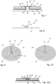
- Weitere praktische Vorteile und Ausführungsbeispiele sind nachfolgend in Verbindung mit den Figuren beschrieben. Es zeigen:
- Fig. 1
- schematisch: eine Querschnittsdarstellung eines Teils eines aus dem Stand der Technik bekannten Vibrationssensors,
- Fig. 2
- eine Querschnittsdarstellung eines Teils eines ersten Ausführungsbeispiels eines Vibrationssensors,
- Fig. 3
- die Elektrode des in
Fig. 2 gezeigten Vibrationssensors, - Fig. 4
- eine perspektivische Darstellung des Piezoaktors aus
Fig. 2 , mit Blick auf die der Membran abgewandte Seite, - Fig. 5
- eine Darstellung wie in
Fig. 4 , jedoch mit Blick auf die der Membran zugewandte Seite, - Fig. 6
- eine Querschnittsdarstellung eines Teils eines weiteren Ausführungsbeispiels eines Vibrationssensors,
- Fig. 7
- eine genauere Darstellung eines Teils des Vibrationssensors aus
Fig. 6 , - Fig. 8
- die Elektrode aus
Fig. 7 , - Fig. 9
- eine perspektivische Darstellung des Piezoaktors aus
Fig. 7 , mit Blick auf die der Membran abgewandte Seite, - Fig. 10
- eine perspektivische Darstellung des Piezoaktors aus
Fig. 7 , mit Blick auf die der Membran zugewandte Seite, - Fig. 10a
- eine Querschnittsdarstellung eines Teils eines weiteren Ausführungsbeispiels eines Vibrationssensors,
- Fig. 11 bis 14
- Querschnittsdarstellungen von Teilen weiterer Ausführungsbeispielen eines Vibrationssensors.
- Fig. 15
- Eine Ausschnittsvergrößerung eines Schnitts in Längsrichtung der Aussparung in einem weiteren Ausführungsbeispiel.
- In
Fig. 1 ist ein Teil eines aus dem Stand der Technik bekannten Vibrationssensors skizzenhaft gezeigt. - Ein Piezoaktor 16 mit ringscheibenförmigem Piezoelement 18 ist hierbei auf ein isolierendes Ausgleichselement 44 aus keramischem Material geklebt. Der Aufbau von Piezoaktor 16 und Ausgleichselement 44 ist ebenfalls durch eine Klebeverbindung auf einer Membran 12 fixiert. Die Membran 12 geht in ein Gehäuse 10 über oder ist hieran befestigt. Durch Anlegen eines elektrischen Potentials an das Piezoelement 18 kann die Membran 12 bei einem solchen Aufbau in Schwingung versetzt werden. Auf der äußeren Seite der Membran 12 können sich weitere mechanisch schwingfähige Elemente, wie beispielsweise Gabelzinken 62, 64 einer Schwinggabel befinden, die in
Fig. 1 durch gestrichelte Linien lediglich angedeutet sind. Die der Membran zugewandte Seite des Piezoaktors ist nicht frei zugänglich und kann somit nicht direkt kontaktiert werden. - Der in
Fig. 2 teilweise gezeigte Vibrationssensor dient zur Detektion von Füllständen, Grenzständen oder zur Überwachung von Prozessparametern und umfasst eine in Schwingung versetzbare Membran 12. Die Membran 12, das Gehäuse 10 und die Gabelzinken 62, 64 können wie inFig. 1 gezeigt ausgebildet sein. Der Vibrationssensor umfasst eine als Piezoaktor 16 ausgebildete Antriebseinheit 14. Der Piezoaktor weist ein Piezoelement 18, und eine mit dem Piezoelement 18 verbundenen Elektrode 20 auf. Die Elektrode weist eine Elektrodenfläche 21 auf. Zudem umfasst der Vibrationssensor eine Klebeverbindung 26, mit deren Hilfe der Piezoaktor 16 so mit der Membran 12 wirkverbunden ist, dass Schwingungen des Piezoaktors 16 auf die Membran 12 übertragbar sind und umgekehrt. Zudem umfasst der Vibrationssensor eine Elektronik 22 und eine elektrische Verbindung 24 zwischen der Elektronik 22 und der Elektrodenfläche 21. - Das Piezoelement 18 weist eine Aussparung 32 auf und die elektrische Verbindung 24 verläuft durch die Aussparung 32.
- Das Piezoelement 18 weist eine erste, der Membran 12 zugewandte Seite 28 auf. Die Elektrodenfläche 21 ist ausschließlich auf dieser ersten Seite 28 angeordnet. Das Piezoelement 18 weist eine zweite, der Membran 12 abgewandte Seite 30 auf. Die Aussparung 32 reicht von der ersten Seite 28 bis zur zweiten Seite 30 durch das Zentrum des Piezoelements 18 hindurch.
- Der Piezoaktor 16 ist als verklebte Ringscheibe 34 ausgebildet, mit zentrischer Umkontaktierung 36. Das Piezoelement 18 und die Elektrode 20 sind jeweils um eine Rotationsachse 38 rotationssymmetrisch.
- Die Elektrode 20 weist zusätzlich zu der ebenen Elektrodenfläche 21 einen in die Aussparung 32 reichenden Verbindungsabschnitt 23 auf und die elektrische Verbindung 24 umfasst diesen Verbindungsabschnitt 23.
- Die elektrische Verbindung 24 umfasst zudem einen in der Aussparung 32 angeordneten, kreuzschraffiert dargestellten leitfähigen Klebstoff 40. Genauer gesagt umfasst die elektrische Verbindung 24 eine Kontaktierung der elektrischen Leitung 72 mit dem Verbindungsabschnitt 23 und diese Kontaktierung umfasst den leitfähigen Klebstoff 40.
- Der leitfähige Klebstoff 40 füllt die Aussparung 32 bei dem in
Fig. 2 gezeigten Ausführungsbeispiel vollständig aus und verbindet den Verbindungsabschnitt 23 der Elektrode 20 und die elektrische Leitung 72 elektrisch und mechanisch miteinander. Hierzu ist zunächst die Klebeverbindung 26 herstellbar und nach deren Aushärten der leitfähige Klebstoff 40 aufbringbar und aushärtbar. - Wie
Fig. 2 ebenfalls zeigt, umfasst der Sensor ein Ausgleichselement 44 zwischen der Membran 12 und dem Piezoaktor 16 in Form einer Ausgleichskeramik und die Klebeverbindung 26 ist zwischen dem Piezoaktor 16 und dem Ausgleichselement 44 angeordnet. Das Ausgleichselement 44 ist seinerseits mit der Membran 12 verklebt, was inFig. 2 nicht explizit dargestellt ist. - Wie
Fig. 2 und z. B.Fig. 4 zeigen, ist an der der Membran 12 abgewandten Seite 30 des Piezoelements 18 eine weitere Elektrode 45 angeordnet und der Sensor umfasst eine weitere elektrische Verbindung 74 zwischen der weiteren Elektrode 45 und der Elektronik 22. Die weitere Elektrode 45 hat die Form eines Kreisrings 66, ist um die Aussparung 32 herum angeordnet und erstreckt sich zumindest nahezu auf der gesamten der Membran 12 abgewandten Seite des Piezoelements 18 mit Ausnahme eines um die Aussparung 32 herum angeordneten inneren Kreisrings 68, zur Isolation der weiteren Elektrode 45 von der Elektrode 20. - Wie
Fig. 2 auch zeigt, erstreckt sich das Piezoelement 18 in einer Ebene 70 und weist eine in dieser Ebene 70 liegende Grundfläche auf. Die aktive Fläche des Piezoelements ist größer als 7/10 oder 8/10 oder 9/10 der Grundfläche des Piezoelements. Zudem ist zu erkennen, dass der Sensor nur zwei elektrische Verbindungsbereiche 80, 82 zu den Elektroden 20, 45 des Piezoaktors 16 aufweist. -
Fig. 3 verdeutlicht die Form der Elektrode 20 des inFig. 2 gezeigten Ausführungsbeispiels, mit der ebenen, kreisringförmigen Elektrodenfläche 21 und dem Verbindungsabschnitt 23. WieFig. 2 und Fig. 3 zeigen, erstreckt sich die Elektrode 20 über zueinander geneigte Flächen und hat in dem in diesen Figuren gezeigten Ausführungsbeispiel die Form einer Kreisfläche mit Loch und an den Rändern des Lochs angrenzendem Hohlzylinder. - Die
Figuren 4 und 5 verdeutlichen den Aufbau des Piezoaktors 16 mit kreisringförmigem Piezoelement 18, wie oben beschriebener Elektrode 20 und weiterer, kreisringförmiger Elektrode 45. - Die
Fig. 6 bis 10 zeigen ein weiteres Ausführungsbeispiel. Wie am besten ausFig. 7 zu erkennen, ist bei diesem Ausführungsbeispiel die Aussparung 32 des Piezoelements nicht vollständig mit leitfähigem Klebstoff gefüllt, sondern in dieser Aussparung ist ein Positioniermittel 46 angeordnet. Zur Kontaktierung der Elektrodenfläche 21 umfasst der Verbindungsabschnitt 23 zusätzlich einen auf der der Membran abgewandten Seite 30 des Piezoelements verlaufenden Bereich 42. Dieser Bereich 42 ist, wie etwaFig. 8 und 9 zeigen, kreisringförmig und kragenförmig, sowie um die Aussparung 32 des Piezoelements 18 herum angeordnet. - Wie erneut
Fig. 7 zeigt, umfasst die elektrische Verbindung 24 eine Kontaktierung der elektrischen Leitung 72 mit diesem Bereich 42 mittels leitfähigem Klebstoffs 40. - Die
Fig. 9 und 10 verdeutlichen den Aufbau des Piezoantriebs 16 mit kreisringförmigem Piezoelement 18, wie oben beschriebener Elektrode 20 mit den Bereich 42 umfassenden Verbindungsabschnitt 23 und weiterer, kreisringförmiger Elektrode 45. -
Fig. 10a zeigt eine Variante, bei der Verbindungsabschnitt 23 der Elektrode, wie bei dem in denFig. 6 bis 10 gezeigten Ausführungsbeispiel, zusätzlich einen auf der der Membran abgewandten Seite 30 des Piezoelements verlaufenden Bereich 42 aufweist, jedoch kein Positionierungsmittel 46 vorhanden ist. Wie bei dem inFig. 2 gezeigten Ausführungsbeispiel füllt der leitfähige Klebstoff 40 die Aussparung 32 des Piezoelements vollständig aus. - Die
Figuren 6 und11 bis 12 zeigen verschiedene Ausgestaltungen von Positioniermitteln 46 zur Positionierung des Piezoaktors 16 und des Ausgleichselements 44 relativ zur Membran 12. -
Fig. 6 zeigt als Positioniermittel 46 einen zylindrischen Stempel 48 des Ausgleichselements 44 auf der dem Piezoaktor 16 zugewandten Seite des Ausgleichselements 44, der in der Aussparung 32 des Piezoelements angeordnet ist. Die Höhe 50 des Stempels entspricht der Höhe 52 des Piezoelements. -
Fig. 11 zeigt als Positioniermittel 46 zwei beidseitig angeordnete Zentrierzapfen 54, 56 an dem Ausgleichselement 44, die in die Aussparung 32 des Piezoelements bzw. in eine korrespondierende Ausnehmung 76 der Membran eingreifen. -
Fig. 12 zeigt als Positioniermittel 46 einen einstückig mit der Membran gebildeten Membranzentrierzapfen 58, der durch eine Ausnehmung 78 des Ausgleichselements und in die Aussparung 32 des Piezoelements greift. -
Fig. 13 zeigt als Positioniermittel 46 einen Membranzentrierzapfen 58, der ein elektrisch nicht leitfähiges Material umfasst und mit der Membran 12 durch Kleben verbunden ist. -
Fig. 14 zeigt als Positioniermittel 46 zusätzlich zu dem zylindrischen Stempel 48 eine Membranvertiefung 60, zur Aufnahme des Ausgleichselements 44. -
Figur 15 zeigt in einer Ausschnittsvergrößerung einen Schnitt in Längsrichtung der Aussparung 32 durch ein weiteres Ausführungsbeispiel eines Vibrationssensors mit einem Piezoaktor 16, wie er in denFiguren 4 und 5 gezeigt ist. - Die elektrische Kontaktierung des Piezoelements 18 erfolgt in diesem Ausführungsbeispiel einerseits durch einen Innenleiter 86 einer Koaxialleitung 84, der in der Aussparung 32 des Piezoelements angeordnet und mit dem leitfähigen Klebstoff 40 mit diesem sowohl elektrisch als auch mechanisch verbunden ist. Die weitere Elektrode 45 ist mit dem Außenleiter 88 der Koaxialleitung 84 verbunden, der ebenfalls mittels eines leitfähigen Klebstoffes 40 mechanisch und elektrisch leitend mit dieser verbunden ist.
- Dadurch, dass das Piezoelement 18 aufgrund der lediglich zentralen Kontaktierung vollkommen rotationssymmetrisch ausgestaltet werden kann, treten weniger Spannungen aufgrund der Verformungen des Piezos auf, wodurch sich unter anderem die mechanische Belastbarkeit und Haltbarkeit des Piezoelements 18 deutlich verlängert. Ferner verringert sich dadurch, dass eine radial weiter außen liegende Kontaktierungsstelle wegfällt, zusätzlich die Steifigkeit wodurch eine größere Amplitude generiert werden kann.
-
- 10
- Gehäuse
- 12
- Membran
- 14
- Antriebseinheit
- 16
- Piezoaktor
- 18
- Piezoelement
- 20
- Elektrode
- 21
- Elektrodenfläche
- 22
- Elektronik
- 23
- Verbindungsabschnitt der Elektrode
- 24
- elektrische Verbindung
- 26
- Klebeverbindung
- 28
- der Membran zugewandte Seite des Piezoelements
- 30
- der Membran abgewandte Seite des Piezoelements
- 32
- Aussparung des Piezoelements
- 34
- verklebte Ringscheibe
- 36
- zentrische Umkontaktierung
- 38
- Rotationsachse
- 40
- leitfähiger Klebstoff
- 42
- auf der der Membran abgewandte Seite des Piezoelements verlaufender Bereich des Verbindungsabschnitts
- 44
- Ausgleichselement
- 45
- weitere Elektrode
- 46
- Positioniermittel
- 48
- zylindrischer Stempel des Ausgleichselements
- 50
- Höhe des zylindrischen Stempels
- 52
- Höhe des Piezoelements
- 54
- Zentrierzapfen des Ausgleichselements
- 56
- Zentrierzapfen des Ausgleichselements
- 58
- Membranzentrierzapfen
- 60
- Membranvertiefung
- 62
- Gabelzinke
- 64
- Gabelzinke
- 66
- Kreisring
- 68
- innerer Kreisring
- 70
- Ebene
- 72
- elektrische Leitung
- 74
- weitere elektrische Verbindung
- 76
- Ausnehmung der Membran
- 78
- Ausnehmung des Ausgleichselements
- 80
- elektrischer Verbindungsbereich
- 82
- elektrischer Verbindungsbereich
- 84
- Koaxialleitung
- 86
- Innenleiter
- 88
- Außenleiter
Claims (16)
- Vibrationssensor, zur Detektion von Füllständen, Grenzständen oder zur Überwachung von Prozessparametern, umfassend:- eine in Schwingung versetzbare Membran (12),- eine Antriebseinheit (14), wobei die Antriebseinheit (14) einen Piezoaktor (16) umfasst, der ein Piezoelement (18), und eine mit dem Piezoelement (18) verbundene Elektrode (20) mit einer Elektrodenfläche (21) aufweist,- eine Klebeverbindung (26), mit deren Hilfe der Piezoaktor (16) so mit der Membran (12) wirkverbunden ist, dass Schwingungen des Piezoaktors (16) auf die Membran (12) übertragbar sind,- eine Elektronik (22),- eine elektrische Verbindung (24) zwischen der Elektronik (22) und der Elektrodenfläche (21),wobei das Piezoelement (18) eine Aussparung (32) aufweist und die elektrische Verbindung (24) durch die Aussparung (32) verläuft.
- Vibrationssensor nach Anspruch 1,
dadurch gekennzeichnet, dass
das Piezoelement (18) eine erste, der Membran (12) zugewandte Seite (28) und eine zweite, der Membran (12) abgewandte Seite (30) aufweist, und die Elektrodenfläche (21) auf der ersten Seite (28) angeordnet ist. - Vibrationssensor nach Anspruch 1 oder 2,
dadurch gekennzeichnet, dass
die Aussparung (32) durch das Zentrum des Piezoelements (18) verläuft. - Vibrationssensor nach einem der Ansprüche 1 bis 3,
dadurch gekennzeichnet, dass
der Piezoaktor (16) rotationssymmetrisch ist. - Vibrationssensor nach einem der Ansprüche 1 bis 4,
dadurch gekennzeichnet, dass
der Piezoaktor (16) als in dem Sensor verklebte Ringscheibe (34) ausgebildet ist, mit zentrischer Umkontaktierung (36). - Vibrationssensor nach einem der Ansprüche 1 bis 5,
dadurch gekennzeichnet, dass
die elektrische Verbindung (24) einen in die Aussparung (32) reichenden Verbindungsabschnitt (23) der Elektrode (20) umfasst. - Vibrationssensor nach Anspruch 6,
dadurch gekennzeichnet, dass
der Verbindungsabschnitt (23) einen auf der der Membran abgewandten Seite (30) des Piezoelements verlaufenden Bereich (42) aufweist. - Vibrationssensor nach einem der Ansprüche 1 bis 7,
dadurch gekennzeichnet, dass
die elektrische Verbindung (24) einen in der Aussparung (32) angeordneten leitfähigen Klebstoff (40) umfasst. - Vibrationssensor nach einem der Ansprüche 1 bis 8,
dadurch gekennzeichnet, dass
der Sensor ein Ausgleichselement (44) zwischen der Membran (12) und dem Piezoaktor (16) aufweist und die Klebeverbindung (26) zwischen dem Piezoaktor (16) und dem Ausgleichselement (44) angeordnet ist. - Vibrationssensor nach einem der Ansprüche 1 bis 9,
dadurch gekennzeichnet, dass
an der der Membran abgewandten Seite (30) des Piezoelements eine weitere Elektrode (45) angeordnet ist. - Vibrationssensor nach einem der Ansprüche 1 bis 10,
dadurch gekennzeichnet, dass
der Sensor Positioniermittel (46) umfasst, zur Positionierung des Piezoaktors (16) und/oder des Ausgleichselements (44) relativ zur Membran (12). - Vibrationssensor nach Anspruch 11,
dadurch gekennzeichnet, dass
die Positioniermittel (46) einen zylindrischen Stempel (48) des Ausgleichselements (44) auf der dem Piezoaktor (16) zugewandten Seite des Ausgleichselements (44) umfassen. - Vibrationssensor nach Anspruch 11 oder 12,
dadurch gekennzeichnet, dass
die Positioniermittel (46) zwei beidseitig angeordnete Zentrierzapfen (54, 56) an dem Ausgleichselement (44) umfassen. - Vibrationssensor nach einem der Ansprüche 11 bis 13,
dadurch gekennzeichnet, dass
die Positioniermittel (46) einen Membranzentrierzapfen (58) umfassen. - Vibrationssensor nach einem der Ansprüche 11 bis 14,
dadurch gekennzeichnet, dass
die Positioniermittel (46) eine Membranvertiefung (60) zur Aufnahme des Ausgleichselements (44) umfassen. - Vibrationssensor nach einem der vorhergehenden Ansprüche,
dadurch gekennzeichnet, dass
die elektrische Verbindung (24) als Innenleiter (86) einer koaxialen Verbindung ausgebildet ist, vorzugsweise als Innenleiter (86) eines Koaxialkabels, wobei der Innenleiter (86) wenigstens teilweise in die Aussparung (32) ragt, vorzugsweise dies wenigstens zur Hälfte, weiter bevorzugt zu wenigstens 80%, besonders bevorzugt annähernd vollständig durchdringt und dort elektrisch mit der Elektrodenfläche (21) verbunden ist.
Applications Claiming Priority (1)
| Application Number | Priority Date | Filing Date | Title |
|---|---|---|---|
| DE102023107707.4A DE102023107707A1 (de) | 2023-03-27 | 2023-03-27 | Vibrationssensor |
Publications (1)
| Publication Number | Publication Date |
|---|---|
| EP4439021A1 true EP4439021A1 (de) | 2024-10-02 |
Family
ID=92632610
Family Applications (1)
| Application Number | Title | Priority Date | Filing Date |
|---|---|---|---|
| EP24165718.8A Pending EP4439021A1 (de) | 2023-03-27 | 2024-03-22 | Vibrationssensor |
Country Status (4)
| Country | Link |
|---|---|
| US (1) | US20240328849A1 (de) |
| EP (1) | EP4439021A1 (de) |
| CN (1) | CN118706252A (de) |
| DE (1) | DE102023107707A1 (de) |
Citations (9)
| Publication number | Priority date | Publication date | Assignee | Title |
|---|---|---|---|---|
| DE19523461C1 (de) * | 1995-06-28 | 1996-07-11 | Endress Hauser Gmbh Co | Vorrichtung zur Feststellung und/oder Überwachung eines vorbestimmten Füllstandes in einem Behälter |
| EP0985916A1 (de) * | 1998-09-09 | 2000-03-15 | Endress + Hauser GmbH + Co. | Vorrichtung zur Feststellung und/oder Überwachung eines vorbestimmten Füllstandes in einem Behälter |
| DE10260088A1 (de) * | 2002-12-19 | 2004-08-05 | Endress + Hauser Gmbh + Co. Kg | Vorrichtung zur Bestimmung und/oder Überwachung mindestens einer physikalischen Größe mit einem Piezoantrieb zur Schwingungserregung und -detektion |
| DE10350086A1 (de) * | 2003-10-27 | 2005-06-02 | Siemens Ag | Sensoreinrichtung zum Erfassen eines Zustands eines Fluids |
| DE102014101372B4 (de) * | 2014-02-04 | 2015-10-08 | Vega Grieshaber Kg | Vibrationssensor mit geklebtem Antrieb |
| DE102016108553A1 (de) * | 2016-05-09 | 2017-11-09 | Vega Grieshaber Kg | Piezoelektrisch angetriebener Vibrationsgrenzschalter mit optimierter Wirkfläche |
| EP3537117A1 (de) * | 2018-03-06 | 2019-09-11 | VEGA Grieshaber KG | Piezoelektrische sende- und/oder empfangseinrichtung für einen vibrationssensor, vibrationssensor mit einer solchen piezoelektrischen sende- und/oder empfangseinrichtung sowie verfahren zur herstellung einer piezoelektrischen sende- und/oder empfangseinrichtung für einen vibrationssensor |
| DE102019111384B3 (de) * | 2019-05-02 | 2020-09-03 | Vega Grieshaber Kg | Piezoelektrische Sende- und/oder Empfangseinrichtung und Vibrationsgrenzstandsensor mit einer solchen |
| DE102019120685A1 (de) * | 2019-07-31 | 2021-02-04 | Vega Grieshaber Kg | Piezostapelantrieb eines Vibrationsgrenzschalters mit stirnseitiger Befestigung |
Family Cites Families (2)
| Publication number | Priority date | Publication date | Assignee | Title |
|---|---|---|---|---|
| GB0803900D0 (en) * | 2008-03-01 | 2008-04-09 | Mobrey Ltd | Vibrating element apparatus |
| DE102011088304B4 (de) * | 2011-12-12 | 2023-09-21 | Endress+Hauser SE+Co. KG | Vorrichtung zur Bestimmung und/oder Überwachung mindestens einer Prozessgröße |
-
2023
- 2023-03-27 DE DE102023107707.4A patent/DE102023107707A1/de active Pending
-
2024
- 2024-03-21 CN CN202410326400.5A patent/CN118706252A/zh active Pending
- 2024-03-22 EP EP24165718.8A patent/EP4439021A1/de active Pending
- 2024-03-26 US US18/616,262 patent/US20240328849A1/en active Pending
Patent Citations (9)
| Publication number | Priority date | Publication date | Assignee | Title |
|---|---|---|---|---|
| DE19523461C1 (de) * | 1995-06-28 | 1996-07-11 | Endress Hauser Gmbh Co | Vorrichtung zur Feststellung und/oder Überwachung eines vorbestimmten Füllstandes in einem Behälter |
| EP0985916A1 (de) * | 1998-09-09 | 2000-03-15 | Endress + Hauser GmbH + Co. | Vorrichtung zur Feststellung und/oder Überwachung eines vorbestimmten Füllstandes in einem Behälter |
| DE10260088A1 (de) * | 2002-12-19 | 2004-08-05 | Endress + Hauser Gmbh + Co. Kg | Vorrichtung zur Bestimmung und/oder Überwachung mindestens einer physikalischen Größe mit einem Piezoantrieb zur Schwingungserregung und -detektion |
| DE10350086A1 (de) * | 2003-10-27 | 2005-06-02 | Siemens Ag | Sensoreinrichtung zum Erfassen eines Zustands eines Fluids |
| DE102014101372B4 (de) * | 2014-02-04 | 2015-10-08 | Vega Grieshaber Kg | Vibrationssensor mit geklebtem Antrieb |
| DE102016108553A1 (de) * | 2016-05-09 | 2017-11-09 | Vega Grieshaber Kg | Piezoelektrisch angetriebener Vibrationsgrenzschalter mit optimierter Wirkfläche |
| EP3537117A1 (de) * | 2018-03-06 | 2019-09-11 | VEGA Grieshaber KG | Piezoelektrische sende- und/oder empfangseinrichtung für einen vibrationssensor, vibrationssensor mit einer solchen piezoelektrischen sende- und/oder empfangseinrichtung sowie verfahren zur herstellung einer piezoelektrischen sende- und/oder empfangseinrichtung für einen vibrationssensor |
| DE102019111384B3 (de) * | 2019-05-02 | 2020-09-03 | Vega Grieshaber Kg | Piezoelektrische Sende- und/oder Empfangseinrichtung und Vibrationsgrenzstandsensor mit einer solchen |
| DE102019120685A1 (de) * | 2019-07-31 | 2021-02-04 | Vega Grieshaber Kg | Piezostapelantrieb eines Vibrationsgrenzschalters mit stirnseitiger Befestigung |
Also Published As
| Publication number | Publication date |
|---|---|
| US20240328849A1 (en) | 2024-10-03 |
| DE102023107707A1 (de) | 2024-10-02 |
| CN118706252A (zh) | 2024-09-27 |
Similar Documents
| Publication | Publication Date | Title |
|---|---|---|
| DE102009029490B4 (de) | Füllstandsmessgerät | |
| DE10023302C2 (de) | Piezoelektrisch erregbares Schwingelement | |
| EP1134038A1 (de) | Vorrichtung zur Feststellung und/oder Überwachung eines vorbestimmten Füllstandes in einem Behälter | |
| DE10028319A1 (de) | Elektromechanischer Wandler | |
| EP3746749B1 (de) | Ultraschallwandler mit einer piezokeramik und verfahren zur herstellung eines solchen ultraschallwandlers | |
| EP3600698A1 (de) | Schallwandler, mit in schwingfähige membran integriertem piezokeramischem wandlerelement | |
| WO1999053475A1 (de) | Kontaktelement für einen ultraschallsensor | |
| EP3537117A1 (de) | Piezoelektrische sende- und/oder empfangseinrichtung für einen vibrationssensor, vibrationssensor mit einer solchen piezoelektrischen sende- und/oder empfangseinrichtung sowie verfahren zur herstellung einer piezoelektrischen sende- und/oder empfangseinrichtung für einen vibrationssensor | |
| EP3548857A1 (de) | Messwertaufnehmer zum gleichzeitigen messen einer kraft, die sowohl dynamisch als auch statisch sein kann | |
| DE102023107707A1 (de) | Vibrationssensor | |
| DE102023107706B3 (de) | Vibrationssensor | |
| DE10350086B4 (de) | Sensoreinrichtung zum Erfassen eines Füllstands oder einer Viskosität eines Fluids | |
| WO2025011941A1 (de) | Vibrationssensor | |
| WO1998000242A1 (de) | Ultraschallwandler mit kontaktglied | |
| DE3500613A1 (de) | Piezoresistive druckmesszelle | |
| DE202012003185U1 (de) | Schwingvorrichtung für eine Füllstandsmesseinheit | |
| WO2000019178A2 (de) | Druckgeber | |
| DE102020131591B4 (de) | Vibrationssensor mit kapazitiver Schwingungsmessung | |
| DE102012205168B4 (de) | Schwingvorrichtung für eine Füllstandsmesseinheit sowie Verfahren zur Montage der Schwingvorrichtung | |
| WO2026057287A1 (de) | Vibrationssensor | |
| EP3374235B1 (de) | Akustischer sensor zum aussenden und/oder empfangen von akustischen signalen | |
| WO2013135273A1 (de) | Sensoreinrichtung zum erfassen von schallemissionen | |
| WO2016184604A1 (de) | Akustischer sensor zum senden und empfangen akustischer signale | |
| WO2026082344A1 (de) | Drucksensor zur bestimmung und/oder überwachung eines drucks eines mediums | |
| EP3159533B1 (de) | Kraftstoffinjektor |
Legal Events
| Date | Code | Title | Description |
|---|---|---|---|
| PUAI | Public reference made under article 153(3) epc to a published international application that has entered the european phase |
Free format text: ORIGINAL CODE: 0009012 |
|
| STAA | Information on the status of an ep patent application or granted ep patent |
Free format text: STATUS: THE APPLICATION HAS BEEN PUBLISHED |
|
| AK | Designated contracting states |
Kind code of ref document: A1 Designated state(s): AL AT BE BG CH CY CZ DE DK EE ES FI FR GB GR HR HU IE IS IT LI LT LU LV MC ME MK MT NL NO PL PT RO RS SE SI SK SM TR |
|
| STAA | Information on the status of an ep patent application or granted ep patent |
Free format text: STATUS: REQUEST FOR EXAMINATION WAS MADE |
|
| 17P | Request for examination filed |
Effective date: 20250331 |