EP4438976A1 - Refrigeration cycle device - Google Patents
Refrigeration cycle device Download PDFInfo
- Publication number
- EP4438976A1 EP4438976A1 EP24719037.4A EP24719037A EP4438976A1 EP 4438976 A1 EP4438976 A1 EP 4438976A1 EP 24719037 A EP24719037 A EP 24719037A EP 4438976 A1 EP4438976 A1 EP 4438976A1
- Authority
- EP
- European Patent Office
- Prior art keywords
- refrigerant
- heat source
- compressor
- flow path
- refrigeration cycle
- Prior art date
- Legal status (The legal status is an assumption and is not a legal conclusion. Google has not performed a legal analysis and makes no representation as to the accuracy of the status listed.)
- Pending
Links
Images





Classifications
-
- F—MECHANICAL ENGINEERING; LIGHTING; HEATING; WEAPONS; BLASTING
- F25—REFRIGERATION OR COOLING; COMBINED HEATING AND REFRIGERATION SYSTEMS; HEAT PUMP SYSTEMS; MANUFACTURE OR STORAGE OF ICE; LIQUEFACTION SOLIDIFICATION OF GASES
- F25B—REFRIGERATION MACHINES, PLANTS OR SYSTEMS; COMBINED HEATING AND REFRIGERATION SYSTEMS; HEAT PUMP SYSTEMS
- F25B1/00—Compression machines, plants or systems with non-reversible cycle
-
- F—MECHANICAL ENGINEERING; LIGHTING; HEATING; WEAPONS; BLASTING
- F25—REFRIGERATION OR COOLING; COMBINED HEATING AND REFRIGERATION SYSTEMS; HEAT PUMP SYSTEMS; MANUFACTURE OR STORAGE OF ICE; LIQUEFACTION SOLIDIFICATION OF GASES
- F25B—REFRIGERATION MACHINES, PLANTS OR SYSTEMS; COMBINED HEATING AND REFRIGERATION SYSTEMS; HEAT PUMP SYSTEMS
- F25B45/00—Arrangements for charging or discharging refrigerant
-
- F—MECHANICAL ENGINEERING; LIGHTING; HEATING; WEAPONS; BLASTING
- F25—REFRIGERATION OR COOLING; COMBINED HEATING AND REFRIGERATION SYSTEMS; HEAT PUMP SYSTEMS; MANUFACTURE OR STORAGE OF ICE; LIQUEFACTION SOLIDIFICATION OF GASES
- F25B—REFRIGERATION MACHINES, PLANTS OR SYSTEMS; COMBINED HEATING AND REFRIGERATION SYSTEMS; HEAT PUMP SYSTEMS
- F25B13/00—Compression machines, plants or systems, with reversible cycle
-
- F—MECHANICAL ENGINEERING; LIGHTING; HEATING; WEAPONS; BLASTING
- F25—REFRIGERATION OR COOLING; COMBINED HEATING AND REFRIGERATION SYSTEMS; HEAT PUMP SYSTEMS; MANUFACTURE OR STORAGE OF ICE; LIQUEFACTION SOLIDIFICATION OF GASES
- F25B—REFRIGERATION MACHINES, PLANTS OR SYSTEMS; COMBINED HEATING AND REFRIGERATION SYSTEMS; HEAT PUMP SYSTEMS
- F25B41/00—Fluid-circulation arrangements
- F25B41/20—Disposition of valves, e.g. of on-off valves or flow control valves
- F25B41/24—Arrangement of shut-off valves for disconnecting a part of the refrigerant cycle, e.g. an outdoor part
-
- F—MECHANICAL ENGINEERING; LIGHTING; HEATING; WEAPONS; BLASTING
- F25—REFRIGERATION OR COOLING; COMBINED HEATING AND REFRIGERATION SYSTEMS; HEAT PUMP SYSTEMS; MANUFACTURE OR STORAGE OF ICE; LIQUEFACTION SOLIDIFICATION OF GASES
- F25B—REFRIGERATION MACHINES, PLANTS OR SYSTEMS; COMBINED HEATING AND REFRIGERATION SYSTEMS; HEAT PUMP SYSTEMS
- F25B49/00—Arrangement or mounting of control or safety devices
- F25B49/02—Arrangement or mounting of control or safety devices for compression type machines, plants or systems
-
- F—MECHANICAL ENGINEERING; LIGHTING; HEATING; WEAPONS; BLASTING
- F25—REFRIGERATION OR COOLING; COMBINED HEATING AND REFRIGERATION SYSTEMS; HEAT PUMP SYSTEMS; MANUFACTURE OR STORAGE OF ICE; LIQUEFACTION SOLIDIFICATION OF GASES
- F25B—REFRIGERATION MACHINES, PLANTS OR SYSTEMS; COMBINED HEATING AND REFRIGERATION SYSTEMS; HEAT PUMP SYSTEMS
- F25B9/00—Compression machines, plants or systems, in which the refrigerant is air or other gas of low boiling point
- F25B9/002—Compression machines, plants or systems, in which the refrigerant is air or other gas of low boiling point characterised by the refrigerant
- F25B9/008—Compression machines, plants or systems, in which the refrigerant is air or other gas of low boiling point characterised by the refrigerant the refrigerant being carbon dioxide
-
- F—MECHANICAL ENGINEERING; LIGHTING; HEATING; WEAPONS; BLASTING
- F25—REFRIGERATION OR COOLING; COMBINED HEATING AND REFRIGERATION SYSTEMS; HEAT PUMP SYSTEMS; MANUFACTURE OR STORAGE OF ICE; LIQUEFACTION SOLIDIFICATION OF GASES
- F25B—REFRIGERATION MACHINES, PLANTS OR SYSTEMS; COMBINED HEATING AND REFRIGERATION SYSTEMS; HEAT PUMP SYSTEMS
- F25B2309/00—Gas cycle refrigeration machines
- F25B2309/06—Compression machines, plants or systems characterised by the refrigerant being carbon dioxide
- F25B2309/061—Compression machines, plants or systems characterised by the refrigerant being carbon dioxide with cycle highest pressure above the supercritical pressure
-
- F—MECHANICAL ENGINEERING; LIGHTING; HEATING; WEAPONS; BLASTING
- F25—REFRIGERATION OR COOLING; COMBINED HEATING AND REFRIGERATION SYSTEMS; HEAT PUMP SYSTEMS; MANUFACTURE OR STORAGE OF ICE; LIQUEFACTION SOLIDIFICATION OF GASES
- F25B—REFRIGERATION MACHINES, PLANTS OR SYSTEMS; COMBINED HEATING AND REFRIGERATION SYSTEMS; HEAT PUMP SYSTEMS
- F25B2313/00—Compression machines, plants or systems with reversible cycle not otherwise provided for
- F25B2313/023—Compression machines, plants or systems with reversible cycle not otherwise provided for using multiple indoor units
- F25B2313/0233—Compression machines, plants or systems with reversible cycle not otherwise provided for using multiple indoor units in parallel arrangements
-
- F—MECHANICAL ENGINEERING; LIGHTING; HEATING; WEAPONS; BLASTING
- F25—REFRIGERATION OR COOLING; COMBINED HEATING AND REFRIGERATION SYSTEMS; HEAT PUMP SYSTEMS; MANUFACTURE OR STORAGE OF ICE; LIQUEFACTION SOLIDIFICATION OF GASES
- F25B—REFRIGERATION MACHINES, PLANTS OR SYSTEMS; COMBINED HEATING AND REFRIGERATION SYSTEMS; HEAT PUMP SYSTEMS
- F25B2313/00—Compression machines, plants or systems with reversible cycle not otherwise provided for
- F25B2313/031—Sensor arrangements
- F25B2313/0314—Temperature sensors near the indoor heat exchanger
-
- F—MECHANICAL ENGINEERING; LIGHTING; HEATING; WEAPONS; BLASTING
- F25—REFRIGERATION OR COOLING; COMBINED HEATING AND REFRIGERATION SYSTEMS; HEAT PUMP SYSTEMS; MANUFACTURE OR STORAGE OF ICE; LIQUEFACTION SOLIDIFICATION OF GASES
- F25B—REFRIGERATION MACHINES, PLANTS OR SYSTEMS; COMBINED HEATING AND REFRIGERATION SYSTEMS; HEAT PUMP SYSTEMS
- F25B2345/00—Details for charging or discharging refrigerants; Service stations therefor
- F25B2345/001—Charging refrigerant to a cycle
-
- F—MECHANICAL ENGINEERING; LIGHTING; HEATING; WEAPONS; BLASTING
- F25—REFRIGERATION OR COOLING; COMBINED HEATING AND REFRIGERATION SYSTEMS; HEAT PUMP SYSTEMS; MANUFACTURE OR STORAGE OF ICE; LIQUEFACTION SOLIDIFICATION OF GASES
- F25B—REFRIGERATION MACHINES, PLANTS OR SYSTEMS; COMBINED HEATING AND REFRIGERATION SYSTEMS; HEAT PUMP SYSTEMS
- F25B2400/00—Component parts or details not otherwise provided for in this subclass
- F25B2400/16—Receivers
-
- F—MECHANICAL ENGINEERING; LIGHTING; HEATING; WEAPONS; BLASTING
- F25—REFRIGERATION OR COOLING; COMBINED HEATING AND REFRIGERATION SYSTEMS; HEAT PUMP SYSTEMS; MANUFACTURE OR STORAGE OF ICE; LIQUEFACTION SOLIDIFICATION OF GASES
- F25B—REFRIGERATION MACHINES, PLANTS OR SYSTEMS; COMBINED HEATING AND REFRIGERATION SYSTEMS; HEAT PUMP SYSTEMS
- F25B2600/00—Control issues
- F25B2600/02—Compressor control
- F25B2600/025—Compressor control by controlling speed
-
- F—MECHANICAL ENGINEERING; LIGHTING; HEATING; WEAPONS; BLASTING
- F25—REFRIGERATION OR COOLING; COMBINED HEATING AND REFRIGERATION SYSTEMS; HEAT PUMP SYSTEMS; MANUFACTURE OR STORAGE OF ICE; LIQUEFACTION SOLIDIFICATION OF GASES
- F25B—REFRIGERATION MACHINES, PLANTS OR SYSTEMS; COMBINED HEATING AND REFRIGERATION SYSTEMS; HEAT PUMP SYSTEMS
- F25B2600/00—Control issues
- F25B2600/25—Control of valves
- F25B2600/2513—Expansion valves
-
- F—MECHANICAL ENGINEERING; LIGHTING; HEATING; WEAPONS; BLASTING
- F25—REFRIGERATION OR COOLING; COMBINED HEATING AND REFRIGERATION SYSTEMS; HEAT PUMP SYSTEMS; MANUFACTURE OR STORAGE OF ICE; LIQUEFACTION SOLIDIFICATION OF GASES
- F25B—REFRIGERATION MACHINES, PLANTS OR SYSTEMS; COMBINED HEATING AND REFRIGERATION SYSTEMS; HEAT PUMP SYSTEMS
- F25B2700/00—Sensing or detecting of parameters; Sensors therefor
- F25B2700/19—Pressures
-
- F—MECHANICAL ENGINEERING; LIGHTING; HEATING; WEAPONS; BLASTING
- F25—REFRIGERATION OR COOLING; COMBINED HEATING AND REFRIGERATION SYSTEMS; HEAT PUMP SYSTEMS; MANUFACTURE OR STORAGE OF ICE; LIQUEFACTION SOLIDIFICATION OF GASES
- F25B—REFRIGERATION MACHINES, PLANTS OR SYSTEMS; COMBINED HEATING AND REFRIGERATION SYSTEMS; HEAT PUMP SYSTEMS
- F25B2700/00—Sensing or detecting of parameters; Sensors therefor
- F25B2700/19—Pressures
- F25B2700/193—Pressures of the compressor
- F25B2700/1931—Discharge pressures
-
- F—MECHANICAL ENGINEERING; LIGHTING; HEATING; WEAPONS; BLASTING
- F25—REFRIGERATION OR COOLING; COMBINED HEATING AND REFRIGERATION SYSTEMS; HEAT PUMP SYSTEMS; MANUFACTURE OR STORAGE OF ICE; LIQUEFACTION SOLIDIFICATION OF GASES
- F25B—REFRIGERATION MACHINES, PLANTS OR SYSTEMS; COMBINED HEATING AND REFRIGERATION SYSTEMS; HEAT PUMP SYSTEMS
- F25B2700/00—Sensing or detecting of parameters; Sensors therefor
- F25B2700/19—Pressures
- F25B2700/193—Pressures of the compressor
- F25B2700/1933—Suction pressures
-
- F—MECHANICAL ENGINEERING; LIGHTING; HEATING; WEAPONS; BLASTING
- F25—REFRIGERATION OR COOLING; COMBINED HEATING AND REFRIGERATION SYSTEMS; HEAT PUMP SYSTEMS; MANUFACTURE OR STORAGE OF ICE; LIQUEFACTION SOLIDIFICATION OF GASES
- F25B—REFRIGERATION MACHINES, PLANTS OR SYSTEMS; COMBINED HEATING AND REFRIGERATION SYSTEMS; HEAT PUMP SYSTEMS
- F25B2700/00—Sensing or detecting of parameters; Sensors therefor
- F25B2700/21—Temperatures
-
- F—MECHANICAL ENGINEERING; LIGHTING; HEATING; WEAPONS; BLASTING
- F25—REFRIGERATION OR COOLING; COMBINED HEATING AND REFRIGERATION SYSTEMS; HEAT PUMP SYSTEMS; MANUFACTURE OR STORAGE OF ICE; LIQUEFACTION SOLIDIFICATION OF GASES
- F25B—REFRIGERATION MACHINES, PLANTS OR SYSTEMS; COMBINED HEATING AND REFRIGERATION SYSTEMS; HEAT PUMP SYSTEMS
- F25B2700/00—Sensing or detecting of parameters; Sensors therefor
- F25B2700/21—Temperatures
- F25B2700/2115—Temperatures of a compressor or the drive means therefor
- F25B2700/21151—Temperatures of a compressor or the drive means therefor at the suction side of the compressor
-
- F—MECHANICAL ENGINEERING; LIGHTING; HEATING; WEAPONS; BLASTING
- F25—REFRIGERATION OR COOLING; COMBINED HEATING AND REFRIGERATION SYSTEMS; HEAT PUMP SYSTEMS; MANUFACTURE OR STORAGE OF ICE; LIQUEFACTION SOLIDIFICATION OF GASES
- F25B—REFRIGERATION MACHINES, PLANTS OR SYSTEMS; COMBINED HEATING AND REFRIGERATION SYSTEMS; HEAT PUMP SYSTEMS
- F25B2700/00—Sensing or detecting of parameters; Sensors therefor
- F25B2700/21—Temperatures
- F25B2700/2115—Temperatures of a compressor or the drive means therefor
- F25B2700/21152—Temperatures of a compressor or the drive means therefor at the discharge side of the compressor
Definitions
- the present disclosure relates to a refrigeration cycle apparatus.
- Patent Literature 1 JP 2008-045769 A discloses a method of heating a refrigerant to be filled by using a heater in order to prevent the refrigerant flowing into a refrigerant circuit due to a rapid pressure decrease at the time of filling a refrigeration cycle apparatus from entering a solid state (dry ice state).
- An object of the present disclosure is to provide a refrigeration cycle apparatus capable of easily suppressing solidification of a filled carbon dioxide refrigerant in a filling operation of filling a refrigerant while activating a compressor.
- a refrigeration cycle apparatus includes a refrigerant circuit, a heat source unit, a utilization unit, a detector, and a control unit.
- the refrigerant circuit includes a compressor, and a carbon dioxide refrigerant flows through the refrigerant circuit.
- the heat source unit accommodates the compressor.
- the utilization unit is connected to the heat source unit via a connecting pipe.
- the detector detects a pressure of the refrigerant in a low pressure flow path of the refrigerant circuit.
- the control unit executes a refrigerant filling operation of moving the refrigerant from a refrigerant storage container to the refrigerant circuit. In the refrigerant filling operation, the control unit controls the number of rotations of the compressor on the basis of a detection value of the detector.
- the refrigeration cycle apparatus can easily suppress solidification of the filled carbon dioxide refrigerant by a simple method of controlling the number of rotations of the compressor in a filling operation of filling the refrigerant while activating the compressor.
- a refrigeration cycle apparatus is the refrigeration cycle apparatus according to the first aspect, in which the low pressure flow path includes a flow path that connects a suction pipe of the compressor and a connecting point between the heat source unit and the connecting pipe.
- a refrigeration cycle apparatus is the refrigeration cycle apparatus according to the first or second aspect, in which the refrigerant circuit includes a filling port that detachably connects the refrigerant storage container.
- a refrigeration cycle apparatus is any of the refrigeration cycle apparatuses according to the first to third aspects, in which the filling port is a service port provided in a shutoff valve.
- a refrigeration cycle apparatus is any of the refrigeration cycle apparatuses according to the first to fourth aspects, in which the heat source unit accommodates the refrigerant storage container connected to the refrigerant circuit.
- a refrigeration cycle apparatus is any of the refrigeration cycle apparatuses according to the first to fifth aspects, in which an amount of the refrigerant filled in the refrigerant storage container is 30% or more of an amount of the refrigerant filled in the heat source unit before the heat source unit is connected to the utilization unit.
- the refrigeration cycle apparatus can easily suppress solidification of the filled carbon dioxide refrigerant by a simple method of controlling the number of rotations of the compressor in the filling operation of filling the refrigerant while activating the compressor.
- a refrigeration cycle apparatus is any of the refrigeration cycle apparatuses according to the first to sixth aspects, in which the refrigerant circuit further includes an expansion mechanism.
- the control unit In the refrigerant filling operation, the control unit further controls an opening degree of the expansion mechanism on the basis of a detection value of the detector.
- a refrigeration cycle apparatus is any of the refrigeration cycle apparatuses according to the first to seventh aspects, in which a plurality of the utilization units is connected to each of the heat source unit.
- the refrigeration cycle apparatus which is multi-type, can also easily suppress solidification of the filled carbon dioxide refrigerant by a simple method of controlling the number of rotations of the compressor in a filling operation of filling the refrigerant while activating the compressor.
- FIG. 1 is a schematic configuration diagram of an air conditioner 1 according to a first embodiment.
- the air conditioner 1 performs a vapor compression refrigeration cycle operation and executes an air conditioning operation (a cooling operation and a heating operation) in an air conditioning target space (not illustrated) such as an indoor space.
- the air conditioner 1 includes one heat source unit 2, one or more utilization units 3, a control unit 4, and a first connecting pipe 6 and a second connecting pipe 7 that connect the heat source unit 2 and the utilization units 3.
- the heat source unit 2, the utilization unit 3, and the connecting pipes 6 and 7 connected to each other constitute a refrigerant circuit 10.
- a refrigerant filled in the refrigerant circuit 10 is carbon dioxide.
- the first connecting pipe 6 and the second connecting pipe 7 are also collectively referred to as connecting pipes 6 and 7.
- the air conditioner 1 is an example of a refrigeration cycle apparatus.
- an inside of a heat source refrigerant flow path 20 (described later) of the heat source unit 2 is not filled with a sufficient amount of refrigerant to execute an air conditioning operation at a time of shipment from a manufacturing factory.
- the air conditioner 1 performs a refrigerant filling operation of filling the refrigerant circuit 10 with the refrigerant filled in a first refrigerant storage container 100 in an installation work of installation at a predetermined installation site.
- the utilization unit 3 is installed in the air conditioning target space.
- the utilization unit 3 includes a utilization refrigerant flow path 30 constituting a part of the refrigerant circuit 10.
- the utilization refrigerant flow path 30 includes a utilization heat exchanger 31.
- the utilization heat exchanger 31 exchanges heat between the refrigerant flowing inside and air in the air conditioning target space.
- One end of the utilization heat exchanger 31 is connected to the first connecting pipe 6.
- the other end of the utilization heat exchanger 31 is connected to the second connecting pipe 7.
- the heat source unit 2 is installed outside the air conditioning target space (outdoor space or the like).
- the heat source unit 2 includes a heat source refrigerant flow path 20 constituting a part of the refrigerant circuit 10.
- the heat source refrigerant flow path 20 includes a compressor 21, a flow path switching mechanism 22, a heat source heat exchanger 23, a heat source expansion mechanism 24, a first shutoff valve 25, a second shutoff valve 26, and a detector 28.
- the compressor 21, the flow path switching mechanism 22, the heat source heat exchanger 23, the heat source expansion mechanism 24, the first shutoff valve 25, and the second shutoff valve 26 are connected to each other via a refrigerant pipe 20a.
- the compressor 21 sucks a low-pressure refrigerant in a refrigeration cycle from a suction pipe 21a, compresses the refrigerant by a compression mechanism (not illustrated), and discharges the compressed refrigerant as a high-pressure refrigerant to a discharge pipe 21b.
- the compressor 21 is a positive displacement compressor.
- the compressor 21 is driven by a motor (not illustrated) whose number of rotations is controlled via an inverter.
- the heat source unit 2 includes only one compressor 21, but the number of compressors 21 is not limited to one and may be plural.
- the control unit 4 controls start, stop, and the number of rotations of the motor included in the compressor 21.
- the flow path switching mechanism 22 switches a flow direction of the refrigerant and changes a state of the refrigerant circuit 10 between a first state and a second state.
- the heat source heat exchanger 23 functions as a radiator for the refrigerant
- the utilization heat exchanger 31 functions as an evaporator for the refrigerant.
- the heat source heat exchanger 23 functions as an evaporator for the refrigerant
- the utilization heat exchanger 31 functions as a radiator for the refrigerant.
- the state of the flow path switching mechanism 22 is changed by the control unit 4.
- the flow path switching mechanism 22 is a four-way switching valve having four ports P1, P2, P3, and P4.
- the port P1 is connected to one end of the heat source heat exchanger 23.
- the port P2 is connected to the discharge pipe 21b of the compressor 21.
- the port P3 is connected to the suction pipe 21a of the compressor 21.
- the port P4 is connected to the second shutoff valve 26. In the first state, the port P1 communicates with the port P2, and the port P3 communicates with the port P4. In the second state, the port P1 communicates with the port P3, and the port P2 communicates with the port P4.
- the flow path switching mechanism 22 is not required to be a four-way switching valve.
- the flow path switching mechanism 22 may be configured by combining a plurality of electromagnetic valves and refrigerant pipes so that the flow direction of the refrigerant can be switched as described above.
- the heat source heat exchanger 23 causes heat exchange between a refrigerant flowing inside and air at an installation site of the heat source unit 2 (heat source air).
- One end of the heat source heat exchanger 23 is connected to the port P1 of the flow path switching mechanism 22.
- the other end of the heat source heat exchanger 23 is connected to the heat source expansion mechanism 24.
- the heat source expansion mechanism 24 adjusts a flow rate of the refrigerant flowing through the heat source refrigerant flow path 20 and decompresses the refrigerant by controlling an opening degree.
- One end of the heat source expansion mechanism 24 is connected to the heat source heat exchanger 23.
- the other end of the heat source expansion mechanism 24 is connected to the first shutoff valve 25.
- the opening degree of the heat source expansion mechanism 24 is controlled by the control unit 4.
- the heat source expansion mechanism 24 is an example of an expansion mechanism.
- the first shutoff valve 25 is a valve provided at a connecting portion between the heat source unit 2 (heat source refrigerant flow path 20) and the first connecting pipe 6. When the first shutoff valve 25 is closed, a flow of the refrigerant between the heat source refrigerant flow path 20 and the first connecting pipe 6 is restricted.
- the first shutoff valve 25 is, for example, a manually operated valve.
- the second shutoff valve 26 is a valve provided at a connecting portion between the heat source unit 2 (heat source refrigerant flow path 20) and the second connecting pipe 7. When the second shutoff valve 26 is closed, a flow of the refrigerant between the heat source refrigerant flow path 20 and the second connecting pipe 7 is restricted.
- the second shutoff valve 26 is, for example, a manually operated valve.
- the second shutoff valve 26 is a three-way valve provided with a service port communicable with the outside of the refrigerant circuit 10.
- the service port of the second shutoff valve 26 functions as a filling port that detachably connects the first refrigerant storage container 100 in the refrigerant filling operation.
- the first shutoff valve 25 and the second shutoff valve 26 are closed at a time of shipment at a manufacturing factory, and are opened at the time of installation work of the air conditioner 1. After completion of the installation work, the first shutoff valve 25 and the second shutoff valve 26 are normally maintained in an open state.
- the detector 28 detects a pressure of the refrigerant in a low pressure flow path 10a.
- the detector 28 is a pressure sensor.
- the low pressure flow path 10a is a flow path included in the refrigerant circuit 10 through which the low-pressure refrigerant in the refrigeration cycle flows.
- the low pressure flow path 10a is a flow path that connects the suction pipe 21a of the compressor 21 and the second shutoff valve 26 that is a connecting point between the heat source unit 2 and the second connecting pipe 7.
- the detector 28 detects the pressure of the refrigerant in the refrigerant pipe 20a connecting the suction pipe 21a of the compressor 21 and the flow path switching mechanism 22.
- the detector 28 may detect the pressure of the refrigerant in another refrigerant pipe 20a (the refrigerant pipe 20a connecting the port P4 and the second shutoff valve 26, or the refrigerant pipe 20a connecting the port P3 and the suction pipe 21a of the compressor 21) included in the low pressure flow path 10a.
- the detector 28 outputs the detected pressure of the refrigerant to the control unit 4.
- the control unit 4 controls operation of electrically connected components constituting the heat source unit 2.
- the control unit 4 controls the components of the heat source unit 2 to achieve the cooling operation, the heating operation, and the refrigerant filling operation described later.
- FIG. 2 is a block diagram of the control unit 4.
- the control unit 4 is electrically connected to the compressor 21, the flow path switching mechanism 22, the heat source expansion mechanism 24, and the detector 28 so as to be able to exchange control signals and information.
- the control unit 4 is implemented by a computer.
- the control unit 4 includes a control calculator and a storage (which are not illustrated).
- a processor such as a CPU or a GPU can be used for the control calculator.
- the control calculator reads a program stored in the storage and performs predetermined calculation processing in accordance with the program. Furthermore, the control calculator can write a calculation result to the storage and read information stored in the storage in accordance with the program.
- the configuration of the control unit 4 described here is merely an example, and the function of the control unit 4 may be implemented by software, hardware, or a combination of software and hardware.
- the connecting pipes 6 and 7 are connection pipes connecting the heat source refrigerant flow path 20 and the utilization refrigerant flow path 30 (in other words, the heat source unit 2 and the utilization unit 3).
- the heat source refrigerant flow path 20, the utilization refrigerant flow path 30, the first connecting pipe 6, and the second connecting pipe 7 are connected to constitute the refrigerant circuit 10.
- the first refrigerant storage container 100 is a container (cylinder) filled with a refrigerant to be filled in the refrigerant circuit 10 in the refrigerant filling operation.
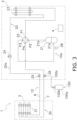
- FIG. 3 is a schematic configuration diagram of the air conditioner 1 to which the first refrigerant storage container 100 is connected.
- the first refrigerant storage container 100 includes a storage portion 100a and a third shutoff valve 100b.
- the first refrigerant storage container 100 is connected to the second shutoff valve 26 via a pipe 100c.
- the storage portion 100a stores the refrigerant.
- the third shutoff valve 100b is a valve to which one end of the pipe 100c is connected. When the third shutoff valve 100b is closed, the flow of the refrigerant between the storage portion 100a and the pipe 100c is restricted.
- the third shutoff valve 100b is, for example, a manually operated valve.
- control unit 4 controls the flow path switching mechanism 22 to the first state. In addition, the control unit 4 controls the opening degree of the heat source expansion mechanism 24 in accordance with a load.
- the control unit 4 activates the compressor 21, the low-pressure refrigerant in the refrigeration cycle is sucked from the suction pipe 21a of the compressor 21, compressed, and discharged from the discharge pipe 21b as a high-pressure refrigerant.
- the high-pressure refrigerant discharged from the compressor 21 is sent to the heat source heat exchanger 23 via the flow path switching mechanism 22, exchanges heat with the heat source air, and is cooled.
- the heat source heat exchanger 23 functions as a radiator.
- the high-pressure refrigerant cooled in the heat source heat exchanger 23 is decompressed when passing through the heat source expansion mechanism 24 to become a low-pressure refrigerant in a gas-liquid two-phase state.
- the low-pressure refrigerant in the gas-liquid two-phase state is sent to the utilization unit 3 via the first shutoff valve 25 and the first connecting pipe 6.
- the refrigerant sent to the utilization unit 3 exchanges heat with air in the air conditioning target space to be heated, and evaporates to become a low-pressure refrigerant.
- the utilization heat exchanger 31 functions as an evaporator.
- the low-pressure refrigerant heated in the utilization heat exchanger 31 is sent to the heat source unit 2 via the second connecting pipe 7, and again sucked into the compressor 21 via the second shutoff valve 26 and the flow path switching mechanism 22.
- control unit 4 controls the flow path switching mechanism 22 to the second state. In addition, the control unit 4 controls the opening degree of the heat source expansion mechanism 24 in accordance with a load.
- the control unit 4 activates the compressor 21, the low-pressure refrigerant in the refrigeration cycle is sucked from the suction pipe 21a of the compressor 21, compressed, and discharged from the discharge pipe 21b as a high-pressure refrigerant.
- the high-pressure refrigerant discharged from the compressor 21 is sent to the utilization unit 3 via the flow path switching mechanism 22, the second shutoff valve 26, and the second connecting pipe 7.
- the high-pressure refrigerant sent to the utilization unit 3 exchanges heat with air in the air conditioning target space in the utilization heat exchanger 31 to be cooled.
- the utilization heat exchanger 31 functions as a radiator.
- the high-pressure refrigerant cooled in the utilization heat exchanger 31 is sent to the heat source unit 2 via the first connecting pipe 6.
- the refrigerant sent to the heat source unit 2 is decompressed when passing through the first shutoff valve 25 and the heat source expansion mechanism 24 to become a low-pressure refrigerant in a gas-liquid two-phase state.
- the low-pressure refrigerant in the gas-liquid two-phase state flows into the heat source heat exchanger 23.
- the low-pressure refrigerant in the gas-liquid two-phase state that has flowed into the heat source heat exchanger 23 exchanges heat with the heat source air and is heated to evaporate and become a low-pressure refrigerant.
- the heat source heat exchanger 23 functions as an evaporator.
- the low-pressure refrigerant heated by the heat source heat exchanger 23 is again sucked into the compressor 21 via the flow path switching mechanism 22.
- the refrigerant filling operation is an operation of moving (filling) the refrigerant from the first refrigerant storage container 100 to the entire refrigerant circuit 10.
- the refrigerant filling operation is typically an operation executed by the air conditioner 1 in the refrigerant filling operation performed after the installation work in which the air conditioner 1 is installed at a predetermined installation site.
- the installation work includes a step of installing each of the heat source unit 2 and the utilization unit 3 at an installation site and a step of connecting the heat source unit 2 and the utilization unit 3 via the connecting pipes 6 and 7 to form the refrigerant circuit 10.
- FIG. 4 is a flowchart of processing in the refrigerant filling operation.
- control unit 4 controls the number of rotations of the compressor 21 on the basis of a detection value of the detector 28.
- the refrigerant filling operation will be described in detail.
- an operator or the like performing the installation work connects the first refrigerant storage container 100 via the pipe 100c to the refrigerant circuit 10 of the air conditioner 1, which is installed at a predetermined installation site and in which the first shutoff valve 25 and the second shutoff valve 26 are opened, as a preparation before starting the refrigerant filling operation.
- the pipe 100c connected to the first refrigerant storage container 100 is connected to the service port of the second shutoff valve 26 functioning as a filling port.
- the third shutoff valve 100b is opened, the refrigerant filled in the first refrigerant storage container 100 flows into the refrigerant circuit 10 via the service port of the second shutoff valve 26.
- the refrigerant filling operation is started when the operator or the like instructs the control unit 4 (start).
- step S11 the control unit 4 activates the compressor 21, sets the flow path switching mechanism 22 to the first state or the second state, and proceeds to step S12.
- step S12 the control unit 4 acquires the detection value of the detector 28, and proceeds to step S13.
- step S13 the control unit 4 controls the number of rotations of the compressor 21 on the basis of the detection value of the detector 28 so that the refrigerant flowing into refrigerant circuit 10 does not enter a solid state (dry ice state). Specifically, the control unit 4 controls the number of rotations of the compressor 21 so that the detection value (in other words, the pressure of the refrigerant in the low pressure flow path 10a) of the detector 28 does not become equal to or less than 0.52 MPa, which is a pressure at a triple point of carbon dioxide.
- the control unit 4 proceeds to step S14.
- the flow of the refrigerant sucked from the suction pipe 21a of the compressor 21 is similar to that in the cooling operation or the heating operation described above, and will not be described.
- the number of rotations of the compressor 21 may be increased again in order to secure a pressure difference between the first refrigerant storage container 100 and the refrigerant circuit 10.
- step S14 the control unit 4 determines whether the refrigerant circuit 10 has been filled with a sufficient amount of refrigerant for executing the air conditioning operation. If the refrigerant circuit has been filled with a sufficient amount of refrigerant (Yes), the control unit 4 proceeds to step S15. If the refrigerant circuit has not been filled with a sufficient amount of refrigerant (No), the control unit 4 proceeds to step S12. Specifically, the determination as to whether a sufficient amount of refrigerant for executing the air conditioning operation has been filled is made on the basis of whether the pressure of the refrigerant in the radiator and the temperature of the refrigerant at an outlet of the radiator have reached predetermined thresholds values.
- the operator or the like may determine whether the refrigerant circuit 10 is filled with a sufficient amount of refrigerant for executing the air conditioning operation. For example, when the weight of the first refrigerant storage container 100 is less than a predetermined value, the operator or the like determines that a sufficient amount of refrigerant has been filled, and can instruct the control unit 4 to that effect.
- step S 15 the control unit 4 stops the compressor 21 and ends the refrigerant filling operation (end).
- the first refrigerant storage container 100 and the pipe 100c are removed from the air conditioner 1. Accordingly, the filling operation ends.
- the air conditioner 1 includes the refrigerant circuit 10, the heat source unit 2, the utilization unit 3, the detector 28, and the control unit 4.
- the refrigerant circuit 10 includes the compressor 21, and a carbon dioxide refrigerant flows through the refrigerant circuit 10.
- the heat source unit 2 accommodates the compressor 21.
- the utilization unit 3 is connected to the heat source unit 2 via the second connecting pipe 7.
- the detector 28 detects the pressure of the refrigerant in the low pressure flow path 10a of the refrigerant circuit 10.
- the control unit 4 executes the refrigerant filling operation of moving the refrigerant from the first refrigerant storage container 100 to the refrigerant circuit 10. In the refrigerant filling operation, the control unit 4 controls the number of rotations of the compressor 21 on the basis of a detection value of the detector 28.
- the compressor is activated during the filling operation to suck the refrigerant into the refrigerant circuit in order to avoid a situation where the refrigerant cannot be filled or the filling takes time due to an insufficient pressure difference between the refrigerant storage container and the refrigerant circuit.
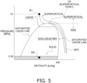
- the carbon dioxide refrigerant has a specific enthalpy of less than 430 kJ/kg, the carbon dioxide refrigerant is in the solid state (dry ice state) when the pressure decreases to a triple point pressure (about 0.52 MPa) of carbon dioxide or less.
- a refrigerant filled in a cylinder or the like and having a temperature of 30°C and a pressure of 12 MPa changes its phase to the solid state at point Q2 where the temperature and the pressure are lower than those of the carbon dioxide triple point (triple point temperature: -56.56°C, triple point pressure: 0.52 MPa) when the pressure of the low pressure flow path 10a becomes lower than the carbon dioxide triple point due to activation of the compressor 21.
- the refrigerant thus having entered the solid state flows through the refrigerant circuit 10, and damages components constituting the refrigerant circuit 10.
- the control unit 4 controls the number of rotations of the compressor 21 so that the detection value (in other words, the pressure of the refrigerant in the low pressure flow path 10a) of the detector 28 does not become equal to or less than 0.52 MPa, which is the triple point pressure of carbon dioxide. Therefore, the pressure of the refrigerant filled from the first refrigerant storage container 100 into the refrigerant circuit 10 is prevented from becoming lower than the triple point pressure of carbon dioxide, and the refrigerant is prevented from entering the solid state in the refrigerant circuit 10.
- the air conditioner 1 can easily suppress solidification of the filled carbon dioxide refrigerant by a simple method of controlling the number of rotations of the compressor 21 in the filling operation of filling the refrigerant while activating the compressor 21.
- the low pressure flow path 10a is a flow path that connects the suction pipe 21a of the compressor 21 and the second shutoff valve 26 that is a connecting point between the heat source unit 2 and the second connecting pipe 7.
- the refrigerant circuit 10 includes the second shutoff valve 26 functioning as a filling port that detachably connects the first refrigerant storage container 100.
- the filling port is a service port provided in the second shutoff valve 26.
- the detector 28 may be a temperature sensor as long as the detector can detect the pressure of the refrigerant in the low pressure flow path 10a.
- the control unit 4 calculates the pressure of the refrigerant in the low pressure flow path 10a on the basis of the temperature of the refrigerant detected by the detector 28.
- the control unit 4 of the air conditioner 1 may further control the opening degree of the heat source expansion mechanism 24 in addition to the number of rotations of the compressor 21 in step S13 of the refrigerant filling operation. Specifically, in step S13, the control unit 4 controls the number of rotations of the compressor 21 and the opening degree of the heat source expansion mechanism 24 on the basis of the detection value of the detector 28 so that the refrigerant flowing into the refrigerant circuit 10 does not enter the solid state (dry ice state).
- the filling port is not required to be a service port provided in the second shutoff valve 26.
- the first shutoff valve 25 may be provided with a service port that functions as a filling port.
- a filling port dedicated for filling may be provided in the refrigerant circuit 10.
- FIG. 6 is a schematic configuration diagram of the air conditioner 1 according to Modification A4.
- the air conditioner 1 according to the first embodiment is different from the air conditioner 1 according to Modification A4 in that the air conditioner 1 according to Modification A4 includes a plurality of (two) utilization units 3 connected to the heat source unit 2, and the utilization units 3 include the utilization expansion mechanism 32.
- the number of the utilization units 3 is not limited to two, and may be three or more.
- the utilization expansion mechanism 32 adjusts a flow rate of the refrigerant flowing through the utilization refrigerant flow path 30 and decompresses the refrigerant by controlling an opening degree.
- One end of the utilization expansion mechanism 32 is connected to the first connecting pipe 6.
- the other end of the utilization expansion mechanism 32 is connected to the utilization heat exchanger 31.
- the opening degree of the utilization expansion mechanism 32 is controlled by the control unit 4.
- the utilization expansion mechanism 32 is an example of an expansion mechanism.
- control unit 4 of the air conditioner 1 controls the opening degree of the utilization expansion mechanism 32 in accordance with an air conditioning load in the indoor space.
- the control unit 4 of the air conditioner 1 may further control the opening degree of the heat source expansion mechanism 24 or the utilization expansion mechanism 32 in addition to the number of rotations of the compressor 21 in step S13 of the refrigerant filling operation. Specifically, when the control unit 4 sets the flow path switching mechanism 22 to the first state in step S11, the control unit 4 controls the number of rotations of the compressor 21 and the opening degree of the utilization expansion mechanism 32 in step S13 on the basis of the detection value of the detector 28 so that the refrigerant flowing into the refrigerant circuit 10 does not enter the solid state (dry ice state).
- control unit 4 sets the flow path switching mechanism 22 to the second state in step S11, the control unit 4 controls the number of rotations of the compressor 21 and the opening degree of the heat source expansion mechanism 24 in step S13 on the basis of the detection value of the detector 28 so that the refrigerant flowing into the refrigerant circuit 10 does not enter the solid state (dry ice state).
- the detection value of the detector 28 changes from a value larger than a first threshold value, which is a pressure higher than 0.52 MPa by a predetermined value, to a value equal to or less than the first threshold value
- the number of rotations of the compressor 21 is only required to be made smaller than the number of rotations before the detection value of the detector 28 becomes equal to or less than the first threshold value
- the opening degree of the heat source expansion mechanism 24 is only required to be larger than the opening degree before the detection value of the detector 28 becomes equal to or less than the first threshold value.
- the detection value of the detector 28 becomes equal to or less than the first threshold value
- the number of rotations of the compressor 21 is decreased, the opening degree of the heat source expansion mechanism 24 is increased, and then the detection value of the detector 28 becomes equal to or more than a second threshold value higher than the first threshold value, the number of rotations of the compressor 21 may be increased and the opening degree of the heat source expansion mechanism 24 may be decreased again in order to secure a pressure difference between the first refrigerant storage container 100 and the refrigerant circuit 10.
- the volume of the refrigerant circuit 10 is larger than the volume of the refrigerant circuit 10 of a pair type air conditioner including only one utilization unit. Therefore, in the multi-type air conditioner, the ratio of the amount of refrigerant filled in the refrigerant circuit 10 before the filling operation to the volume of the refrigerant circuit 10 tends to be smaller than the ratio in the pair type air conditioner. Therefore, in the multi-type air conditioner, when the compressor 21 is activated in the filling operation of carbon dioxide refrigerant, the pressure in the low pressure flow path 10a tends to be low, and there is a high possibility that the carbon dioxide refrigerant that has flowed into the low pressure flow path enters the solid state.
- the air conditioner 1 according to Modification A4 which is multi-type, can also easily suppress solidification of the filled carbon dioxide refrigerant by a simple method of controlling the number of rotations of the compressor 21.
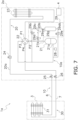
- FIG. 7 is a schematic configuration diagram of the air conditioner 1a according to the second embodiment.
- FIG. 8 is a block diagram of the control unit 4 of the air conditioner 1a.
- a main difference between the air conditioner 1a and the air conditioner 1 is that the air conditioner 1a includes a heat source unit 2a further including a refrigerant amount adjuster 29 instead of the heat source unit 2.
- the refrigerant amount adjuster 29 stores the refrigerant to be filled in the refrigerant circuit 10 in an installation work of the air conditioner 1a.
- the refrigerant amount adjuster 29 is included in the heat source refrigerant flow path 20 of the heat source unit 2a.
- the refrigerant circuit 10 is filled with a larger amount of refrigerant than in the heat source unit 2.
- the refrigerant amount adjuster 29 includes a second refrigerant storage container 29a, a pressure adjustment valve 29b, a check valve 29c, an electromagnetic valve 29d, and an expansion mechanism 29e.
- the second refrigerant storage container 29a is a container (tank) that stores at least a part of the refrigerant to be filled in the heat source refrigerant flow path 20, is connected to the refrigerant circuit 10, and stores a surplus refrigerant generated in the refrigerant circuit 10.
- the second refrigerant storage container 29a is accommodated in the heat source unit 2.
- the second refrigerant storage container 29a has a first port 29aa and a second port 29ab.
- the second refrigerant storage container 29a is filled with the refrigerant, for example, in a manufacturing factory of the air conditioner 1a.
- the amount of the refrigerant filled in the second refrigerant storage container 29a is 30% or more of the amount of the refrigerant filled in the heat source unit 2 (specifically, the heat source refrigerant flow path 20) before the heat source unit 2 is connected to the utilization unit 3.
- the first port 29aa is a port provided for adjusting the pressure inside the second refrigerant storage container 29a.
- the first port 29aa is connected to, via a pressure adjusting pipe 20b, the refrigerant pipe 20a connected to the port P3 of the flow path switching mechanism 22 and the suction pipe 21a of the compressor 21, and the discharge pipe 21b of the compressor 21 .
- the second port 29ab is a port through which the refrigerant flows.
- the second port 29ab is connected to the low pressure flow path 10a via a refrigerant pipe 20a.
- the pressure adjustment valve 29b is a valve that prevents the pressure of the refrigerant in the second refrigerant storage container 29a from becoming excessively high.
- the pressure adjustment valve 29b is provided in the pressure adjusting pipe 20b connected to the refrigerant pipe 20a connected to the port P3 of the flow path switching mechanism 22 and the suction pipe 21a of the compressor 21.
- the pressure adjustment valve 29b opens when the pressure of the refrigerant in the second refrigerant storage container 29a becomes equal to or more than a predetermined value, and releases the refrigerant to the refrigerant pipe 20a connecting the port P3 of the flow path switching mechanism 22 and the suction pipe 21a of the compressor 21.
- the check valve 29c and the electromagnetic valve 29d are valves used to increase the pressure of the refrigerant in the second refrigerant storage container 29a.
- the check valve 29c and the electromagnetic valve 29d are provided in the pressure adjusting pipe 20b connected to the discharge pipe 21b of the compressor 21.
- the electromagnetic valve 29d is opened typically when the refrigerant circuit 10 is filled with the refrigerant in the second refrigerant storage container 29a.
- the check valve 29c prevents the refrigerant from flowing from the second refrigerant storage container 29a to the discharge pipe 21b of the compressor 21.
- the opening and closing of the electromagnetic valve 29d is controlled by the control unit 4.
- the check valve 29c and the electromagnetic valve 29d may be a flow rate adjusting mechanism including an electric valve.
- the expansion mechanism 29e adjusts a flow rate of the refrigerant flowing through the refrigerant pipe 20a connecting the low pressure flow path 10a and the second refrigerant storage container 29a and decompresses the refrigerant.
- the opening degree of the expansion mechanism 29e is controlled by the control unit 4.
- the opening degrees of the expansion mechanism 29e and the electromagnetic valve 29d are controlled to be fully closed or nearly fully closed.
- the operation of the other components of the air conditioner 1a in the air conditioning operation is similar to that of the air conditioner 1, and will not be described.
- the refrigerant filling operation is an operation of moving (filling) the refrigerant from the second refrigerant storage container 29a to the entire refrigerant circuit 10.
- the refrigerant filling operation is executed in a state where the refrigerant circuit 10 is not filled with the refrigerant or is not sufficiently filled with the refrigerant.
- the refrigerant filling operation is performed typically in an installation work in which the air conditioner 1a is installed at a predetermined installation site.
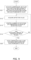
- FIG. 9 is a flowchart of processing in the refrigerant filling operation of the air conditioner 1a.
- the refrigerant filling operation executed by the air conditioner 1 is different from the refrigerant filling operation executed by the air conditioner 1a in that the air conditioner 1a executes step S21 instead of step S11 and executes step S25 instead of step S 15. Therefore, step S21 and step S25 will be mainly described below.
- preparation before starting the refrigerant filling operation (work of connecting the first refrigerant storage container 100 to the refrigerant circuit 10 via the pipe 100c) is unnecessary.
- step S21 the control unit 4 activates the compressor 21, sets the flow path switching mechanism 22 to the first state or the second state, opens the expansion mechanism 29e and the electromagnetic valve 29d to a predetermined opening degree, and proceeds to step S12.
- the control unit 4 may control the opening degree of the expansion mechanism 29e on the basis of a degree of superheating of the refrigerant in the suction pipe 21a or the like.
- step S25 the control unit 4 stops the compressor 21, fully closes the expansion mechanism 29e and the electromagnetic valve 29d, and ends the refrigerant filling operation (end).
- the heat source unit 2 accommodates the second refrigerant storage container 29a connected to the refrigerant circuit 10.
- the air conditioner 1a in which the second refrigerant storage container 29a is connected to the refrigerant circuit 10 in advance can easily suppress solidification of the filled carbon dioxide refrigerant by a simple method of controlling the number of rotations of the compressor 21.
- the amount of the refrigerant accommodated in the second refrigerant storage container 29a is 30% or more of the amount of the refrigerant filled in the heat source unit 2 before the heat source unit 2 is connected to the utilization unit 3.
- the ratio of the amount of refrigerant filled in the heat source unit 2 (in other words, the heat source refrigerant flow path 20) before the heat source unit 2 is connected to the utilization unit 3 to the volume of the heat source refrigerant flow path 20 tends to be small.
- the air conditioner 1a in which the amount of the refrigerant accommodated in the second refrigerant storage container 29a and the amount of the refrigerant filled in the heat source unit 2 before the heat source unit 2 is connected to the utilization unit 3 have the above relationship, the pressure of the heat source refrigerant flow path 20 tends to decrease when the compressor 21 is activated in the filling operation of the carbon dioxide refrigerant, and there is a high possibility that the carbon dioxide refrigerant that has flowed into the air conditioner 1a enters the solid state.
- the air conditioner 1a can easily suppress solidification of the filled carbon dioxide refrigerant by a simple method of controlling the number of rotations of the compressor 21.
- the air conditioner 1 may also have the characteristics of Modification A1, Modification A2, and Modification A4 described above.
- Patent Literature 1 JP 2008-045769 A
Landscapes
- Engineering & Computer Science (AREA)
- Physics & Mathematics (AREA)
- Mechanical Engineering (AREA)
- Thermal Sciences (AREA)
- General Engineering & Computer Science (AREA)
- Chemical & Material Sciences (AREA)
- Chemical Kinetics & Catalysis (AREA)
- Air Conditioning Control Device (AREA)
Abstract
Description
- The present disclosure relates to a refrigeration cycle apparatus.
- A refrigeration cycle apparatus using carbon dioxide as a refrigerant is known. Patent Literature 1 (
JP 2008-045769 A - In a filling operation of filling the refrigerant circuit with the refrigerant from a refrigerant storage container as disclosed in
Patent Literature 1, there is a case where a compressor is activated during the filling operation to suck the refrigerant into the refrigerant circuit in order to avoid a situation where the refrigerant cannot be filled or the filling takes time due to an insufficient pressure difference between the refrigerant storage container and the refrigerant circuit. On the other hand, a carbon dioxide refrigerant enters a solid state (dry ice state) when the pressure decreases. Therefore, when the compressor is activated in the filling operation with the carbon dioxide refrigerant, there is a possibility that the carbon dioxide refrigerant enters the solid state in a low pressure flow path included in the refrigerant circuit. There is a possibility that the refrigerant brought into the solid state damages components constituting the refrigerant circuit. - An object of the present disclosure is to provide a refrigeration cycle apparatus capable of easily suppressing solidification of a filled carbon dioxide refrigerant in a filling operation of filling a refrigerant while activating a compressor.
- A refrigeration cycle apparatus according to a first aspect includes a refrigerant circuit, a heat source unit, a utilization unit, a detector, and a control unit. The refrigerant circuit includes a compressor, and a carbon dioxide refrigerant flows through the refrigerant circuit. The heat source unit accommodates the compressor. The utilization unit is connected to the heat source unit via a connecting pipe. The detector detects a pressure of the refrigerant in a low pressure flow path of the refrigerant circuit. The control unit executes a refrigerant filling operation of moving the refrigerant from a refrigerant storage container to the refrigerant circuit. In the refrigerant filling operation, the control unit controls the number of rotations of the compressor on the basis of a detection value of the detector.
- The refrigeration cycle apparatus can easily suppress solidification of the filled carbon dioxide refrigerant by a simple method of controlling the number of rotations of the compressor in a filling operation of filling the refrigerant while activating the compressor.
- A refrigeration cycle apparatus according to a second aspect is the refrigeration cycle apparatus according to the first aspect, in which the low pressure flow path includes a flow path that connects a suction pipe of the compressor and a connecting point between the heat source unit and the connecting pipe.
- A refrigeration cycle apparatus according to a third aspect is the refrigeration cycle apparatus according to the first or second aspect, in which the refrigerant circuit includes a filling port that detachably connects the refrigerant storage container.
- A refrigeration cycle apparatus according to a fourth aspect is any of the refrigeration cycle apparatuses according to the first to third aspects, in which the filling port is a service port provided in a shutoff valve.
- A refrigeration cycle apparatus according to a fifth aspect is any of the refrigeration cycle apparatuses according to the first to fourth aspects, in which the heat source unit accommodates the refrigerant storage container connected to the refrigerant circuit.
- A refrigeration cycle apparatus according to a sixth aspect is any of the refrigeration cycle apparatuses according to the first to fifth aspects, in which an amount of the refrigerant filled in the refrigerant storage container is 30% or more of an amount of the refrigerant filled in the heat source unit before the heat source unit is connected to the utilization unit.
- Even when the refrigerant storage container is filled with a large amount of refrigerant as compared with the amount of the refrigerant filled in the heat source unit, the refrigeration cycle apparatus can easily suppress solidification of the filled carbon dioxide refrigerant by a simple method of controlling the number of rotations of the compressor in the filling operation of filling the refrigerant while activating the compressor.
- A refrigeration cycle apparatus according to a seventh aspect is any of the refrigeration cycle apparatuses according to the first to sixth aspects, in which the refrigerant circuit further includes an expansion mechanism. In the refrigerant filling operation, the control unit further controls an opening degree of the expansion mechanism on the basis of a detection value of the detector.
- In the refrigeration cycle apparatus, since the pressure of the refrigerant in the low pressure flow path is controlled by the compressor and the expansion mechanism, solidification of the filled carbon dioxide refrigerant can be more reliably suppressed than when the pressure is controlled only by the compressor.
- A refrigeration cycle apparatus according to an eighth aspect is any of the refrigeration cycle apparatuses according to the first to seventh aspects, in which a plurality of the utilization units is connected to each of the heat source unit.
- The refrigeration cycle apparatus, which is multi-type, can also easily suppress solidification of the filled carbon dioxide refrigerant by a simple method of controlling the number of rotations of the compressor in a filling operation of filling the refrigerant while activating the compressor.
-
-
FIG. 1 is a schematic configuration diagram of anair conditioner 1 according to a first embodiment. -
FIG. 2 is a block diagram of acontrol unit 4. -
FIG. 3 is a schematic configuration diagram of theair conditioner 1 to which a firstrefrigerant storage container 100 is connected. -
FIG. 4 is a flowchart of processing in a refrigerant filling operation. -
FIG. 5 is a simplified diagram illustrating a state of pressure-enthalpy of carbon dioxide. -
FIG. 6 is a schematic configuration diagram of anair conditioner 1 according to Modification A4. -
FIG. 7 is a schematic configuration diagram of an air conditioner 1a according to a second embodiment. -
FIG. 8 is a block diagram of acontrol unit 4 of the air conditioner 1a. -
FIG. 9 is a flowchart of processing in a refrigerant filling operation of the air conditioner 1a. -
FIG. 1 is a schematic configuration diagram of anair conditioner 1 according to a first embodiment. Theair conditioner 1 performs a vapor compression refrigeration cycle operation and executes an air conditioning operation (a cooling operation and a heating operation) in an air conditioning target space (not illustrated) such as an indoor space. Theair conditioner 1 includes oneheat source unit 2, one ormore utilization units 3, acontrol unit 4, and a first connecting pipe 6 and a second connectingpipe 7 that connect theheat source unit 2 and theutilization units 3. Theheat source unit 2, theutilization unit 3, and the connectingpipes 6 and 7 connected to each other constitute arefrigerant circuit 10. A refrigerant filled in therefrigerant circuit 10 is carbon dioxide. Hereinafter, the first connecting pipe 6 and the second connectingpipe 7 are also collectively referred to as connectingpipes 6 and 7. Theair conditioner 1 is an example of a refrigeration cycle apparatus. - Although details will be described later, in the
air conditioner 1, an inside of a heat source refrigerant flow path 20 (described later) of theheat source unit 2 is not filled with a sufficient amount of refrigerant to execute an air conditioning operation at a time of shipment from a manufacturing factory. Theair conditioner 1 performs a refrigerant filling operation of filling therefrigerant circuit 10 with the refrigerant filled in a firstrefrigerant storage container 100 in an installation work of installation at a predetermined installation site. - The
utilization unit 3 is installed in the air conditioning target space. Theutilization unit 3 includes a utilizationrefrigerant flow path 30 constituting a part of therefrigerant circuit 10. The utilizationrefrigerant flow path 30 includes autilization heat exchanger 31. - The
utilization heat exchanger 31 exchanges heat between the refrigerant flowing inside and air in the air conditioning target space. One end of theutilization heat exchanger 31 is connected to the first connecting pipe 6. The other end of theutilization heat exchanger 31 is connected to the second connectingpipe 7. - The
heat source unit 2 is installed outside the air conditioning target space (outdoor space or the like). Theheat source unit 2 includes a heat sourcerefrigerant flow path 20 constituting a part of therefrigerant circuit 10. The heat sourcerefrigerant flow path 20 includes acompressor 21, a flowpath switching mechanism 22, a heatsource heat exchanger 23, a heatsource expansion mechanism 24, afirst shutoff valve 25, asecond shutoff valve 26, and adetector 28. Thecompressor 21, the flowpath switching mechanism 22, the heatsource heat exchanger 23, the heatsource expansion mechanism 24, thefirst shutoff valve 25, and thesecond shutoff valve 26 are connected to each other via arefrigerant pipe 20a. - The
compressor 21 sucks a low-pressure refrigerant in a refrigeration cycle from asuction pipe 21a, compresses the refrigerant by a compression mechanism (not illustrated), and discharges the compressed refrigerant as a high-pressure refrigerant to adischarge pipe 21b. Thecompressor 21 is a positive displacement compressor. Thecompressor 21 is driven by a motor (not illustrated) whose number of rotations is controlled via an inverter. In the present embodiment, theheat source unit 2 includes only onecompressor 21, but the number ofcompressors 21 is not limited to one and may be plural. Thecontrol unit 4 controls start, stop, and the number of rotations of the motor included in thecompressor 21. - The flow
path switching mechanism 22 switches a flow direction of the refrigerant and changes a state of therefrigerant circuit 10 between a first state and a second state. When therefrigerant circuit 10 is in the first state, the heatsource heat exchanger 23 functions as a radiator for the refrigerant, and theutilization heat exchanger 31 functions as an evaporator for the refrigerant. When therefrigerant circuit 10 is in the second state, the heatsource heat exchanger 23 functions as an evaporator for the refrigerant, and theutilization heat exchanger 31 functions as a radiator for the refrigerant. The state of the flowpath switching mechanism 22 is changed by thecontrol unit 4. - In the present embodiment, the flow
path switching mechanism 22 is a four-way switching valve having four ports P1, P2, P3, and P4. The port P1 is connected to one end of the heatsource heat exchanger 23. The port P2 is connected to thedischarge pipe 21b of thecompressor 21. The port P3 is connected to thesuction pipe 21a of thecompressor 21. The port P4 is connected to thesecond shutoff valve 26. In the first state, the port P1 communicates with the port P2, and the port P3 communicates with the port P4. In the second state, the port P1 communicates with the port P3, and the port P2 communicates with the port P4. - The flow
path switching mechanism 22 is not required to be a four-way switching valve. For example, the flowpath switching mechanism 22 may be configured by combining a plurality of electromagnetic valves and refrigerant pipes so that the flow direction of the refrigerant can be switched as described above. - The heat
source heat exchanger 23 causes heat exchange between a refrigerant flowing inside and air at an installation site of the heat source unit 2 (heat source air). One end of the heatsource heat exchanger 23 is connected to the port P1 of the flowpath switching mechanism 22. The other end of the heatsource heat exchanger 23 is connected to the heatsource expansion mechanism 24. - The heat
source expansion mechanism 24 adjusts a flow rate of the refrigerant flowing through the heat sourcerefrigerant flow path 20 and decompresses the refrigerant by controlling an opening degree. One end of the heatsource expansion mechanism 24 is connected to the heatsource heat exchanger 23. The other end of the heatsource expansion mechanism 24 is connected to thefirst shutoff valve 25. The opening degree of the heatsource expansion mechanism 24 is controlled by thecontrol unit 4. The heatsource expansion mechanism 24 is an example of an expansion mechanism. - The
first shutoff valve 25 is a valve provided at a connecting portion between the heat source unit 2 (heat source refrigerant flow path 20) and the first connecting pipe 6. When thefirst shutoff valve 25 is closed, a flow of the refrigerant between the heat sourcerefrigerant flow path 20 and the first connecting pipe 6 is restricted. Thefirst shutoff valve 25 is, for example, a manually operated valve. - The
second shutoff valve 26 is a valve provided at a connecting portion between the heat source unit 2 (heat source refrigerant flow path 20) and the second connectingpipe 7. When thesecond shutoff valve 26 is closed, a flow of the refrigerant between the heat sourcerefrigerant flow path 20 and the second connectingpipe 7 is restricted. Thesecond shutoff valve 26 is, for example, a manually operated valve. In the present embodiment, thesecond shutoff valve 26 is a three-way valve provided with a service port communicable with the outside of therefrigerant circuit 10. The service port of thesecond shutoff valve 26 functions as a filling port that detachably connects the firstrefrigerant storage container 100 in the refrigerant filling operation. - The
first shutoff valve 25 and thesecond shutoff valve 26 are closed at a time of shipment at a manufacturing factory, and are opened at the time of installation work of theair conditioner 1. After completion of the installation work, thefirst shutoff valve 25 and thesecond shutoff valve 26 are normally maintained in an open state. - The
detector 28 detects a pressure of the refrigerant in a lowpressure flow path 10a. Thedetector 28 is a pressure sensor. The lowpressure flow path 10a is a flow path included in therefrigerant circuit 10 through which the low-pressure refrigerant in the refrigeration cycle flows. Specifically, the lowpressure flow path 10a is a flow path that connects thesuction pipe 21a of thecompressor 21 and thesecond shutoff valve 26 that is a connecting point between theheat source unit 2 and the second connectingpipe 7. In the present embodiment, thedetector 28 detects the pressure of the refrigerant in therefrigerant pipe 20a connecting thesuction pipe 21a of thecompressor 21 and the flowpath switching mechanism 22. Thedetector 28 may detect the pressure of the refrigerant in anotherrefrigerant pipe 20a (therefrigerant pipe 20a connecting the port P4 and thesecond shutoff valve 26, or therefrigerant pipe 20a connecting the port P3 and thesuction pipe 21a of the compressor 21) included in the lowpressure flow path 10a. Thedetector 28 outputs the detected pressure of the refrigerant to thecontrol unit 4. - The
control unit 4 controls operation of electrically connected components constituting theheat source unit 2. Thecontrol unit 4 controls the components of theheat source unit 2 to achieve the cooling operation, the heating operation, and the refrigerant filling operation described later.FIG. 2 is a block diagram of thecontrol unit 4. Thecontrol unit 4 is electrically connected to thecompressor 21, the flowpath switching mechanism 22, the heatsource expansion mechanism 24, and thedetector 28 so as to be able to exchange control signals and information. - The
control unit 4 is implemented by a computer. Thecontrol unit 4 includes a control calculator and a storage (which are not illustrated). A processor such as a CPU or a GPU can be used for the control calculator. The control calculator reads a program stored in the storage and performs predetermined calculation processing in accordance with the program. Furthermore, the control calculator can write a calculation result to the storage and read information stored in the storage in accordance with the program. The configuration of thecontrol unit 4 described here is merely an example, and the function of thecontrol unit 4 may be implemented by software, hardware, or a combination of software and hardware. - The connecting
pipes 6 and 7 are connection pipes connecting the heat sourcerefrigerant flow path 20 and the utilization refrigerant flow path 30 (in other words, theheat source unit 2 and the utilization unit 3). The heat sourcerefrigerant flow path 20, the utilizationrefrigerant flow path 30, the first connecting pipe 6, and the second connectingpipe 7 are connected to constitute therefrigerant circuit 10. - The first
refrigerant storage container 100 is a container (cylinder) filled with a refrigerant to be filled in therefrigerant circuit 10 in the refrigerant filling operation.FIG. 3 is a schematic configuration diagram of theair conditioner 1 to which the firstrefrigerant storage container 100 is connected. - The first
refrigerant storage container 100 includes astorage portion 100a and athird shutoff valve 100b. The firstrefrigerant storage container 100 is connected to thesecond shutoff valve 26 via apipe 100c. Thestorage portion 100a stores the refrigerant. Thethird shutoff valve 100b is a valve to which one end of thepipe 100c is connected. When thethird shutoff valve 100b is closed, the flow of the refrigerant between thestorage portion 100a and thepipe 100c is restricted. Thethird shutoff valve 100b is, for example, a manually operated valve. - Next, a description will be given of operations of components of the
air conditioner 1. - In the cooling operation, the
control unit 4 controls the flowpath switching mechanism 22 to the first state. In addition, thecontrol unit 4 controls the opening degree of the heatsource expansion mechanism 24 in accordance with a load. - In this state, when the
control unit 4 activates thecompressor 21, the low-pressure refrigerant in the refrigeration cycle is sucked from thesuction pipe 21a of thecompressor 21, compressed, and discharged from thedischarge pipe 21b as a high-pressure refrigerant. The high-pressure refrigerant discharged from thecompressor 21 is sent to the heatsource heat exchanger 23 via the flowpath switching mechanism 22, exchanges heat with the heat source air, and is cooled. In other words, the heatsource heat exchanger 23 functions as a radiator. The high-pressure refrigerant cooled in the heatsource heat exchanger 23 is decompressed when passing through the heatsource expansion mechanism 24 to become a low-pressure refrigerant in a gas-liquid two-phase state. The low-pressure refrigerant in the gas-liquid two-phase state is sent to theutilization unit 3 via thefirst shutoff valve 25 and the first connecting pipe 6. The refrigerant sent to theutilization unit 3 exchanges heat with air in the air conditioning target space to be heated, and evaporates to become a low-pressure refrigerant. In other words, theutilization heat exchanger 31 functions as an evaporator. The low-pressure refrigerant heated in theutilization heat exchanger 31 is sent to theheat source unit 2 via the second connectingpipe 7, and again sucked into thecompressor 21 via thesecond shutoff valve 26 and the flowpath switching mechanism 22. - In the heating operation, the
control unit 4 controls the flowpath switching mechanism 22 to the second state. In addition, thecontrol unit 4 controls the opening degree of the heatsource expansion mechanism 24 in accordance with a load. - In this state, when the
control unit 4 activates thecompressor 21, the low-pressure refrigerant in the refrigeration cycle is sucked from thesuction pipe 21a of thecompressor 21, compressed, and discharged from thedischarge pipe 21b as a high-pressure refrigerant. The high-pressure refrigerant discharged from thecompressor 21 is sent to theutilization unit 3 via the flowpath switching mechanism 22, thesecond shutoff valve 26, and the second connectingpipe 7. The high-pressure refrigerant sent to theutilization unit 3 exchanges heat with air in the air conditioning target space in theutilization heat exchanger 31 to be cooled. In other words, theutilization heat exchanger 31 functions as a radiator. The high-pressure refrigerant cooled in theutilization heat exchanger 31 is sent to theheat source unit 2 via the first connecting pipe 6. The refrigerant sent to theheat source unit 2 is decompressed when passing through thefirst shutoff valve 25 and the heatsource expansion mechanism 24 to become a low-pressure refrigerant in a gas-liquid two-phase state. The low-pressure refrigerant in the gas-liquid two-phase state flows into the heatsource heat exchanger 23. The low-pressure refrigerant in the gas-liquid two-phase state that has flowed into the heatsource heat exchanger 23 exchanges heat with the heat source air and is heated to evaporate and become a low-pressure refrigerant. In other words, the heatsource heat exchanger 23 functions as an evaporator. The low-pressure refrigerant heated by the heatsource heat exchanger 23 is again sucked into thecompressor 21 via the flowpath switching mechanism 22. - The refrigerant filling operation is an operation of moving (filling) the refrigerant from the first
refrigerant storage container 100 to the entirerefrigerant circuit 10. The refrigerant filling operation is typically an operation executed by theair conditioner 1 in the refrigerant filling operation performed after the installation work in which theair conditioner 1 is installed at a predetermined installation site. The installation work includes a step of installing each of theheat source unit 2 and theutilization unit 3 at an installation site and a step of connecting theheat source unit 2 and theutilization unit 3 via the connectingpipes 6 and 7 to form therefrigerant circuit 10.FIG. 4 is a flowchart of processing in the refrigerant filling operation. - In the refrigerant filling operation, the
control unit 4 controls the number of rotations of thecompressor 21 on the basis of a detection value of thedetector 28. Hereinafter, the refrigerant filling operation will be described in detail. - In the filling operation, an operator or the like performing the installation work connects the first
refrigerant storage container 100 via thepipe 100c to therefrigerant circuit 10 of theair conditioner 1, which is installed at a predetermined installation site and in which thefirst shutoff valve 25 and thesecond shutoff valve 26 are opened, as a preparation before starting the refrigerant filling operation. Specifically, thepipe 100c connected to the firstrefrigerant storage container 100 is connected to the service port of thesecond shutoff valve 26 functioning as a filling port. Thereafter, when thethird shutoff valve 100b is opened, the refrigerant filled in the firstrefrigerant storage container 100 flows into therefrigerant circuit 10 via the service port of thesecond shutoff valve 26. Thereafter, the refrigerant filling operation is started when the operator or the like instructs the control unit 4 (start). - In step S11, the
control unit 4 activates thecompressor 21, sets the flowpath switching mechanism 22 to the first state or the second state, and proceeds to step S12. - In step S12, the
control unit 4 acquires the detection value of thedetector 28, and proceeds to step S13. - In step S13, the
control unit 4 controls the number of rotations of thecompressor 21 on the basis of the detection value of thedetector 28 so that the refrigerant flowing intorefrigerant circuit 10 does not enter a solid state (dry ice state). Specifically, thecontrol unit 4 controls the number of rotations of thecompressor 21 so that the detection value (in other words, the pressure of the refrigerant in the lowpressure flow path 10a) of thedetector 28 does not become equal to or less than 0.52 MPa, which is a pressure at a triple point of carbon dioxide. For example, when the detection value of thedetector 28 changes from a value larger than a first threshold value, which is a pressure higher than 0.52 MPa by a predetermined value, to a value equal to or less than the first threshold value, the number of rotations of thecompressor 21 is only required to be made smaller than the number of rotations before the detection value of thedetector 28 becomes equal to or less than the first threshold value. Thereafter, thecontrol unit 4 proceeds to step S14. The flow of the refrigerant sucked from thesuction pipe 21a of thecompressor 21 is similar to that in the cooling operation or the heating operation described above, and will not be described. When the detection value of thedetector 28 becomes equal to or less than the first threshold value and the number of rotations of thecompressor 21 is decreased, and then the detection value of thedetector 28 becomes equal to or more than a second threshold value higher than the first threshold value, the number of rotations of thecompressor 21 may be increased again in order to secure a pressure difference between the firstrefrigerant storage container 100 and therefrigerant circuit 10. - In step S14, the
control unit 4 determines whether therefrigerant circuit 10 has been filled with a sufficient amount of refrigerant for executing the air conditioning operation. If the refrigerant circuit has been filled with a sufficient amount of refrigerant (Yes), thecontrol unit 4 proceeds to step S15. If the refrigerant circuit has not been filled with a sufficient amount of refrigerant (No), thecontrol unit 4 proceeds to step S12. Specifically, the determination as to whether a sufficient amount of refrigerant for executing the air conditioning operation has been filled is made on the basis of whether the pressure of the refrigerant in the radiator and the temperature of the refrigerant at an outlet of the radiator have reached predetermined thresholds values. - The operator or the like may determine whether the
refrigerant circuit 10 is filled with a sufficient amount of refrigerant for executing the air conditioning operation. For example, when the weight of the firstrefrigerant storage container 100 is less than a predetermined value, the operator or the like determines that a sufficient amount of refrigerant has been filled, and can instruct thecontrol unit 4 to that effect. - In step S 15, the
control unit 4 stops thecompressor 21 and ends the refrigerant filling operation (end). - When the refrigerant filling operation is finished, the first
refrigerant storage container 100 and thepipe 100c are removed from theair conditioner 1. Accordingly, the filling operation ends. - (4-1)
Theair conditioner 1 includes therefrigerant circuit 10, theheat source unit 2, theutilization unit 3, thedetector 28, and thecontrol unit 4. - The
refrigerant circuit 10 includes thecompressor 21, and a carbon dioxide refrigerant flows through therefrigerant circuit 10. Theheat source unit 2 accommodates thecompressor 21. Theutilization unit 3 is connected to theheat source unit 2 via the second connectingpipe 7. Thedetector 28 detects the pressure of the refrigerant in the lowpressure flow path 10a of therefrigerant circuit 10. Thecontrol unit 4 executes the refrigerant filling operation of moving the refrigerant from the firstrefrigerant storage container 100 to therefrigerant circuit 10. In the refrigerant filling operation, thecontrol unit 4 controls the number of rotations of thecompressor 21 on the basis of a detection value of thedetector 28. - In the filling operation of filling the refrigerant circuit with the refrigerant from the refrigerant storage container, there is a case where the compressor is activated during the filling operation to suck the refrigerant into the refrigerant circuit in order to avoid a situation where the refrigerant cannot be filled or the filling takes time due to an insufficient pressure difference between the refrigerant storage container and the refrigerant circuit. On the other hand, in a case where the carbon dioxide refrigerant has a specific enthalpy of less than 430 kJ/kg, the carbon dioxide refrigerant is in the solid state (dry ice state) when the pressure decreases to a triple point pressure (about 0.52 MPa) of carbon dioxide or less. Therefore, when the compressor is activated in the filling operation of the carbon dioxide refrigerant, there is a possibility that the pressure of the low
pressure flow path 10a decreases to the triple point pressure of carbon dioxide or less, and the carbon dioxide refrigerant enters the solid state. A description will be given by using a simplified diagram illustrating a state of pressure-enthalpy of carbon dioxide illustrated inFIG. 5 . - For example, a refrigerant filled in a cylinder or the like and having a temperature of 30°C and a pressure of 12 MPa (see point Q1 in
FIG. 5 ) changes its phase to the solid state at point Q2 where the temperature and the pressure are lower than those of the carbon dioxide triple point (triple point temperature: -56.56°C, triple point pressure: 0.52 MPa) when the pressure of the lowpressure flow path 10a becomes lower than the carbon dioxide triple point due to activation of thecompressor 21. There is a possibility that the refrigerant thus having entered the solid state flows through therefrigerant circuit 10, and damages components constituting therefrigerant circuit 10. - In the
air conditioner 1, in the refrigerant filling operation, thecontrol unit 4 controls the number of rotations of thecompressor 21 so that the detection value (in other words, the pressure of the refrigerant in the lowpressure flow path 10a) of thedetector 28 does not become equal to or less than 0.52 MPa, which is the triple point pressure of carbon dioxide. Therefore, the pressure of the refrigerant filled from the firstrefrigerant storage container 100 into therefrigerant circuit 10 is prevented from becoming lower than the triple point pressure of carbon dioxide, and the refrigerant is prevented from entering the solid state in therefrigerant circuit 10. - As described above, the
air conditioner 1 can easily suppress solidification of the filled carbon dioxide refrigerant by a simple method of controlling the number of rotations of thecompressor 21 in the filling operation of filling the refrigerant while activating thecompressor 21. - (4-2)
The lowpressure flow path 10a is a flow path that connects thesuction pipe 21a of thecompressor 21 and thesecond shutoff valve 26 that is a connecting point between theheat source unit 2 and the second connectingpipe 7. - (4-3)
Therefrigerant circuit 10 includes thesecond shutoff valve 26 functioning as a filling port that detachably connects the firstrefrigerant storage container 100. - (4-4)
The filling port is a service port provided in thesecond shutoff valve 26. - The
detector 28 may be a temperature sensor as long as the detector can detect the pressure of the refrigerant in the lowpressure flow path 10a. In this case, thecontrol unit 4 calculates the pressure of the refrigerant in the lowpressure flow path 10a on the basis of the temperature of the refrigerant detected by thedetector 28. - The
control unit 4 of theair conditioner 1 may further control the opening degree of the heatsource expansion mechanism 24 in addition to the number of rotations of thecompressor 21 in step S13 of the refrigerant filling operation. Specifically, in step S13, thecontrol unit 4 controls the number of rotations of thecompressor 21 and the opening degree of the heatsource expansion mechanism 24 on the basis of the detection value of thedetector 28 so that the refrigerant flowing into therefrigerant circuit 10 does not enter the solid state (dry ice state). - In the
air conditioner 1 according to Modification A2, since the pressure of the refrigerant in the lowpressure flow path 10a is controlled by thecompressor 21 and the heatsource expansion mechanism 24, solidification of the filled carbon dioxide refrigerant can be more reliably suppressed than when the pressure is controlled only by thecompressor 21. - The filling port is not required to be a service port provided in the
second shutoff valve 26. For example, thefirst shutoff valve 25 may be provided with a service port that functions as a filling port. In addition, separately from thefirst shutoff valve 25 and thesecond shutoff valve 26, a filling port dedicated for filling may be provided in therefrigerant circuit 10. - A plurality of
utilization units 3 may be connected to each of theheat source unit 2.FIG. 6 is a schematic configuration diagram of theair conditioner 1 according to Modification A4. Theair conditioner 1 according to the first embodiment is different from theair conditioner 1 according to Modification A4 in that theair conditioner 1 according to Modification A4 includes a plurality of (two)utilization units 3 connected to theheat source unit 2, and theutilization units 3 include theutilization expansion mechanism 32. The number of theutilization units 3 is not limited to two, and may be three or more. - The
utilization expansion mechanism 32 adjusts a flow rate of the refrigerant flowing through the utilizationrefrigerant flow path 30 and decompresses the refrigerant by controlling an opening degree. One end of theutilization expansion mechanism 32 is connected to the first connecting pipe 6. The other end of theutilization expansion mechanism 32 is connected to theutilization heat exchanger 31. The opening degree of theutilization expansion mechanism 32 is controlled by thecontrol unit 4. Theutilization expansion mechanism 32 is an example of an expansion mechanism. - In the cooling operation and the heating operation, the
control unit 4 of theair conditioner 1 according to Modification A4 controls the opening degree of theutilization expansion mechanism 32 in accordance with an air conditioning load in the indoor space. - The
control unit 4 of theair conditioner 1 according to Modification A4 may further control the opening degree of the heatsource expansion mechanism 24 or theutilization expansion mechanism 32 in addition to the number of rotations of thecompressor 21 in step S13 of the refrigerant filling operation. Specifically, when thecontrol unit 4 sets the flowpath switching mechanism 22 to the first state in step S11, thecontrol unit 4 controls the number of rotations of thecompressor 21 and the opening degree of theutilization expansion mechanism 32 in step S13 on the basis of the detection value of thedetector 28 so that the refrigerant flowing into therefrigerant circuit 10 does not enter the solid state (dry ice state). When thecontrol unit 4 sets the flowpath switching mechanism 22 to the second state in step S11, thecontrol unit 4 controls the number of rotations of thecompressor 21 and the opening degree of the heatsource expansion mechanism 24 in step S13 on the basis of the detection value of thedetector 28 so that the refrigerant flowing into therefrigerant circuit 10 does not enter the solid state (dry ice state). Specifically, for example, when the detection value of thedetector 28 changes from a value larger than a first threshold value, which is a pressure higher than 0.52 MPa by a predetermined value, to a value equal to or less than the first threshold value, the number of rotations of thecompressor 21 is only required to be made smaller than the number of rotations before the detection value of thedetector 28 becomes equal to or less than the first threshold value, and the opening degree of the heatsource expansion mechanism 24 is only required to be larger than the opening degree before the detection value of thedetector 28 becomes equal to or less than the first threshold value. When the detection value of thedetector 28 becomes equal to or less than the first threshold value, the number of rotations of thecompressor 21 is decreased, the opening degree of the heatsource expansion mechanism 24 is increased, and then the detection value of thedetector 28 becomes equal to or more than a second threshold value higher than the first threshold value, the number of rotations of thecompressor 21 may be increased and the opening degree of the heatsource expansion mechanism 24 may be decreased again in order to secure a pressure difference between the firstrefrigerant storage container 100 and therefrigerant circuit 10. - In a multi-type air conditioner including a plurality of utilization units, the volume of the
refrigerant circuit 10 is larger than the volume of therefrigerant circuit 10 of a pair type air conditioner including only one utilization unit. Therefore, in the multi-type air conditioner, the ratio of the amount of refrigerant filled in therefrigerant circuit 10 before the filling operation to the volume of therefrigerant circuit 10 tends to be smaller than the ratio in the pair type air conditioner. Therefore, in the multi-type air conditioner, when thecompressor 21 is activated in the filling operation of carbon dioxide refrigerant, the pressure in the lowpressure flow path 10a tends to be low, and there is a high possibility that the carbon dioxide refrigerant that has flowed into the low pressure flow path enters the solid state. However, theair conditioner 1 according to Modification A4, which is multi-type, can also easily suppress solidification of the filled carbon dioxide refrigerant by a simple method of controlling the number of rotations of thecompressor 21. - An air conditioner 1a according to a second embodiment will be described focusing on differences from the
air conditioner 1. Hereinafter, characteristics that are same as or corresponding to the characteristics of the first embodiment are denoted by the same reference signs, and will not be described.FIG. 7 is a schematic configuration diagram of the air conditioner 1a according to the second embodiment.FIG. 8 is a block diagram of thecontrol unit 4 of the air conditioner 1a. - A main difference between the air conditioner 1a and the
air conditioner 1 is that the air conditioner 1a includes aheat source unit 2a further including arefrigerant amount adjuster 29 instead of theheat source unit 2. - The
refrigerant amount adjuster 29 stores the refrigerant to be filled in therefrigerant circuit 10 in an installation work of the air conditioner 1a. Therefrigerant amount adjuster 29 is included in the heat sourcerefrigerant flow path 20 of theheat source unit 2a. As a result, in theheat source unit 2a, therefrigerant circuit 10 is filled with a larger amount of refrigerant than in theheat source unit 2. Therefrigerant amount adjuster 29 includes a second refrigerant storage container 29a, apressure adjustment valve 29b, acheck valve 29c, anelectromagnetic valve 29d, and anexpansion mechanism 29e. - The second refrigerant storage container 29a is a container (tank) that stores at least a part of the refrigerant to be filled in the heat source
refrigerant flow path 20, is connected to therefrigerant circuit 10, and stores a surplus refrigerant generated in therefrigerant circuit 10. The second refrigerant storage container 29a is accommodated in theheat source unit 2. The second refrigerant storage container 29a has a first port 29aa and a second port 29ab. The second refrigerant storage container 29a is filled with the refrigerant, for example, in a manufacturing factory of the air conditioner 1a. The amount of the refrigerant filled in the second refrigerant storage container 29a is 30% or more of the amount of the refrigerant filled in the heat source unit 2 (specifically, the heat source refrigerant flow path 20) before theheat source unit 2 is connected to theutilization unit 3. - The first port 29aa is a port provided for adjusting the pressure inside the second refrigerant storage container 29a. The first port 29aa is connected to, via a
pressure adjusting pipe 20b, therefrigerant pipe 20a connected to the port P3 of the flowpath switching mechanism 22 and thesuction pipe 21a of thecompressor 21, and thedischarge pipe 21b of thecompressor 21 . - The second port 29ab is a port through which the refrigerant flows. The second port 29ab is connected to the low
pressure flow path 10a via arefrigerant pipe 20a. - The
pressure adjustment valve 29b is a valve that prevents the pressure of the refrigerant in the second refrigerant storage container 29a from becoming excessively high. Thepressure adjustment valve 29b is provided in thepressure adjusting pipe 20b connected to therefrigerant pipe 20a connected to the port P3 of the flowpath switching mechanism 22 and thesuction pipe 21a of thecompressor 21. Thepressure adjustment valve 29b opens when the pressure of the refrigerant in the second refrigerant storage container 29a becomes equal to or more than a predetermined value, and releases the refrigerant to therefrigerant pipe 20a connecting the port P3 of the flowpath switching mechanism 22 and thesuction pipe 21a of thecompressor 21. - The
check valve 29c and theelectromagnetic valve 29d are valves used to increase the pressure of the refrigerant in the second refrigerant storage container 29a. Thecheck valve 29c and theelectromagnetic valve 29d are provided in thepressure adjusting pipe 20b connected to thedischarge pipe 21b of thecompressor 21. When theelectromagnetic valve 29d is opened during the operation of thecompressor 21, a high-pressure refrigerant discharged from thecompressor 21 is sent to the second refrigerant storage container 29a. Theelectromagnetic valve 29d is opened typically when therefrigerant circuit 10 is filled with the refrigerant in the second refrigerant storage container 29a. Thecheck valve 29c prevents the refrigerant from flowing from the second refrigerant storage container 29a to thedischarge pipe 21b of thecompressor 21. The opening and closing of theelectromagnetic valve 29d is controlled by thecontrol unit 4. Thecheck valve 29c and theelectromagnetic valve 29d may be a flow rate adjusting mechanism including an electric valve. - The
expansion mechanism 29e adjusts a flow rate of the refrigerant flowing through therefrigerant pipe 20a connecting the lowpressure flow path 10a and the second refrigerant storage container 29a and decompresses the refrigerant. The opening degree of theexpansion mechanism 29e is controlled by thecontrol unit 4. - Next, a description will be given of operations of components of the
air conditioner 1. - In both the cooling operation and the heating operation, the opening degrees of the
expansion mechanism 29e and theelectromagnetic valve 29d are controlled to be fully closed or nearly fully closed. The operation of the other components of the air conditioner 1a in the air conditioning operation is similar to that of theair conditioner 1, and will not be described. - The refrigerant filling operation is an operation of moving (filling) the refrigerant from the second refrigerant storage container 29a to the entire
refrigerant circuit 10. The refrigerant filling operation is executed in a state where therefrigerant circuit 10 is not filled with the refrigerant or is not sufficiently filled with the refrigerant. The refrigerant filling operation is performed typically in an installation work in which the air conditioner 1a is installed at a predetermined installation site.FIG. 9 is a flowchart of processing in the refrigerant filling operation of the air conditioner 1a. - The refrigerant filling operation executed by the
air conditioner 1 is different from the refrigerant filling operation executed by the air conditioner 1a in that the air conditioner 1a executes step S21 instead of step S11 and executes step S25 instead of step S 15. Therefore, step S21 and step S25 will be mainly described below. In the installation work of the air conditioner 1a, preparation before starting the refrigerant filling operation (work of connecting the firstrefrigerant storage container 100 to therefrigerant circuit 10 via thepipe 100c) is unnecessary. - In step S21, the
control unit 4 activates thecompressor 21, sets the flowpath switching mechanism 22 to the first state or the second state, opens theexpansion mechanism 29e and theelectromagnetic valve 29d to a predetermined opening degree, and proceeds to step S12. - When the
expansion mechanism 29e is opened, a liquid-back phenomenon may occur in which the liquid-phase refrigerant filled in the second refrigerant storage container 29a flows into thesuction pipe 21a of thecompressor 21 via the lowpressure flow path 10a. Therefore, thecontrol unit 4 may control the opening degree of theexpansion mechanism 29e on the basis of a degree of superheating of the refrigerant in thesuction pipe 21a or the like. - In step S25, the
control unit 4 stops thecompressor 21, fully closes theexpansion mechanism 29e and theelectromagnetic valve 29d, and ends the refrigerant filling operation (end). - (4-1)
Theheat source unit 2 accommodates the second refrigerant storage container 29a connected to therefrigerant circuit 10. - As described above, the air conditioner 1a in which the second refrigerant storage container 29a is connected to the
refrigerant circuit 10 in advance can easily suppress solidification of the filled carbon dioxide refrigerant by a simple method of controlling the number of rotations of thecompressor 21. - (4-2)
The amount of the refrigerant accommodated in the second refrigerant storage container 29a is 30% or more of the amount of the refrigerant filled in theheat source unit 2 before theheat source unit 2 is connected to theutilization unit 3. - In the air conditioner 1a in which a large amount of refrigerant is stored in the second refrigerant storage container 29a, the ratio of the amount of refrigerant filled in the heat source unit 2 (in other words, the heat source refrigerant flow path 20) before the
heat source unit 2 is connected to theutilization unit 3 to the volume of the heat sourcerefrigerant flow path 20 tends to be small. Therefore, in the air conditioner 1a in which the amount of the refrigerant accommodated in the second refrigerant storage container 29a and the amount of the refrigerant filled in theheat source unit 2 before theheat source unit 2 is connected to theutilization unit 3 have the above relationship, the pressure of the heat sourcerefrigerant flow path 20 tends to decrease when thecompressor 21 is activated in the filling operation of the carbon dioxide refrigerant, and there is a high possibility that the carbon dioxide refrigerant that has flowed into the air conditioner 1a enters the solid state. However, even when the second refrigerant storage container 29a is filled with a large amount of refrigerant, the air conditioner 1a can easily suppress solidification of the filled carbon dioxide refrigerant by a simple method of controlling the number of rotations of thecompressor 21. - The
air conditioner 1 may also have the characteristics of Modification A1, Modification A2, and Modification A4 described above. - The embodiments of the present disclosure have been described above. It will be understood that various changes to modes and details can be made without departing from the gist and scope of the present disclosure recited in the claims.
-
- 1, 1a: air conditioner (refrigeration cycle apparatus)
- 2, 2a: heat source unit
- 3: utilization unit
- 4: control unit
- 6: first connecting pipe (connecting pipe)
- 7: second connecting pipe (connecting pipe)
- 10: refrigerant circuit
- 10a: low pressure flow path
- 20: heat source refrigerant flow path
- 20a: refrigerant pipe
- 21: compressor
- 22: flow path switching mechanism
- 23: heat source heat exchanger
- 24: heat source expansion mechanism (expansion mechanism)
- 25: first shutoff valve
- 26: second shutoff valve (shutoff valve)
- 28: detector
- 29a: second refrigerant storage container (refrigerant storage container)
- 30: utilization refrigerant flow path
- 31: utilization heat exchanger
- 32: utilization expansion mechanism (expansion mechanism)
- 100: first refrigerant storage container (refrigerant storage container)
- Patent Literature 1:
JP 2008-045769 A
Claims (8)
- A refrigeration cycle apparatus comprising:a refrigerant circuit (10) that includes a compressor (21) and through which a refrigerant as a carbon dioxide refrigerant flows;a heat source unit (2) that accommodates the compressor;a utilization unit (3) connected to the heat source unit via a connecting pipe (6, 7);a detector (28) that detects a temperature or a pressure of the refrigerant in a low pressure flow path (10a) of the refrigerant circuit; anda control unit (4) that executes a refrigerant filling operation of moving the refrigerant from a refrigerant storage container (29a, 100) to the refrigerant circuit, whereinthe control unit controls a number of rotations of the compressor on a basis of a detection value of the detector in the refrigerant filling operation.
- The refrigeration cycle apparatus according to claim 1, wherein the low pressure flow path includes a flow path that connects a suction pipe of the compressor and a connecting point between the heat source unit and the connecting pipe.
- The refrigeration cycle apparatus according to claim 1 or 2, wherein the refrigerant circuit includes a filling port that detachably connects the refrigerant storage container.
- The refrigeration cycle apparatus according to any one of claims 1 to 3, wherein the filling port is a service port provided in a shutoff valve (26).
- The refrigeration cycle apparatus according to any one of claims 1 to 4, wherein the heat source unit accommodates the refrigerant storage container (29a) connected to the refrigerant circuit.
- The refrigeration cycle apparatus according to any one of claims 1 to 5, wherein an amount of the refrigerant filled in the refrigerant storage container is
30% or more of an amount of the refrigerant filled in the heat source unit before the heat source unit is connected to the utilization unit. - The refrigeration cycle apparatus according to any one of claims 1 to 6, whereinthe refrigerant circuit further includes an expansion mechanism (24), andthe control unit further controls an opening degree of the expansion mechanism on a basis of a detection value of the detector in the refrigerant filling operation.
- The refrigeration cycle apparatus according to any one of claims 1 to 7, wherein a plurality of the utilization units is connected to each of the heat source unit.
Applications Claiming Priority (2)
| Application Number | Priority Date | Filing Date | Title |
|---|---|---|---|
| JP2023023078A JP7598044B2 (en) | 2023-02-17 | 2023-02-17 | Refrigeration Cycle Equipment |
| PCT/JP2024/000755 WO2024171679A1 (en) | 2023-02-17 | 2024-01-15 | Refrigeration cycle device |
Publications (2)
| Publication Number | Publication Date |
|---|---|
| EP4438976A1 true EP4438976A1 (en) | 2024-10-02 |
| EP4438976A4 EP4438976A4 (en) | 2025-02-26 |
Family
ID=90922457
Family Applications (1)
| Application Number | Title | Priority Date | Filing Date |
|---|---|---|---|
| EP24719037.4A Pending EP4438976A4 (en) | 2023-02-17 | 2024-01-15 | Refrigeration cycle device |
Country Status (5)
| Country | Link |
|---|---|
| US (1) | US20250369669A1 (en) |
| EP (1) | EP4438976A4 (en) |
| JP (1) | JP7598044B2 (en) |
| CN (1) | CN120731341A (en) |
| WO (1) | WO2024171679A1 (en) |
Families Citing this family (1)
| Publication number | Priority date | Publication date | Assignee | Title |
|---|---|---|---|---|
| JP2026060052A (en) * | 2024-09-27 | 2026-04-08 | ダイキン工業株式会社 | Refrigeration cycle equipment |
Family Cites Families (9)
| Publication number | Priority date | Publication date | Assignee | Title |
|---|---|---|---|---|
| JP4070583B2 (en) * | 2002-11-14 | 2008-04-02 | 大阪瓦斯株式会社 | Compression heat pump system |
| JP4670329B2 (en) * | 2004-11-29 | 2011-04-13 | 三菱電機株式会社 | Refrigeration air conditioner, operation control method of refrigeration air conditioner, refrigerant amount control method of refrigeration air conditioner |
| JP2007187387A (en) * | 2006-01-13 | 2007-07-26 | Daikin Ind Ltd | Refrigeration apparatus and method for installing the refrigeration apparatus |
| JP4197020B2 (en) | 2006-08-10 | 2008-12-17 | ダイキン工業株式会社 | Refrigerant charging method in refrigeration apparatus using carbon dioxide as refrigerant |
| JP5083282B2 (en) * | 2009-07-31 | 2012-11-28 | ダイキン工業株式会社 | Refrigerant charging method in refrigeration apparatus using carbon dioxide as refrigerant |
| JP5573296B2 (en) * | 2010-03-31 | 2014-08-20 | ダイキン工業株式会社 | Air conditioner |
| JP5673645B2 (en) * | 2012-10-11 | 2015-02-18 | ダイキン工業株式会社 | Outdoor unit |
| JP2016125695A (en) * | 2014-12-26 | 2016-07-11 | ダイキン工業株式会社 | Storage air conditioner |
| JP2020197328A (en) * | 2019-05-31 | 2020-12-10 | シャープ株式会社 | Air conditioner |
-
2023
- 2023-02-17 JP JP2023023078A patent/JP7598044B2/en active Active
-
2024
- 2024-01-15 EP EP24719037.4A patent/EP4438976A4/en active Pending
- 2024-01-15 WO PCT/JP2024/000755 patent/WO2024171679A1/en not_active Ceased
- 2024-01-15 CN CN202480012365.8A patent/CN120731341A/en active Pending
-
2025
- 2025-08-15 US US19/300,748 patent/US20250369669A1/en active Pending
Also Published As
| Publication number | Publication date |
|---|---|
| JP7598044B2 (en) | 2024-12-11 |
| CN120731341A (en) | 2025-09-30 |
| US20250369669A1 (en) | 2025-12-04 |
| EP4438976A4 (en) | 2025-02-26 |
| WO2024171679A1 (en) | 2024-08-22 |
| JP2024117151A (en) | 2024-08-29 |
Similar Documents
| Publication | Publication Date | Title |
|---|---|---|
| EP2808621B1 (en) | Air-conditioning device | |
| EP2960597B1 (en) | Air conditioning device | |
| CN104024764B (en) | Refrigeration apparatus | |
| EP3508796A1 (en) | Freezing apparatus | |
| EP2960596B1 (en) | Air conditioning device | |
| EP2975336B1 (en) | Air conditioner | |
| EP3521721B1 (en) | Air conditioner | |
| EP3690349B1 (en) | Air conditioner | |
| EP3657097B1 (en) | Freezer | |
| EP3657096B1 (en) | Freezer | |
| AU2010238051A1 (en) | Heat source unit | |
| US20250369669A1 (en) | Refrigeration cycle apparatus | |
| EP1553365A2 (en) | Air conditioning system | |
| CN114364929B (en) | Outdoor units and refrigeration cycles | |
| CN108431526B (en) | air conditioner | |
| EP4015939B1 (en) | Refrigeration device | |
| EP4462039A1 (en) | Refrigeration device | |
| JP5201175B2 (en) | Air conditioner | |
| EP3974744A1 (en) | Air conditioning device | |
| EP4624820A1 (en) | Air conditioner | |
| EP4553410A1 (en) | Refrigeration cycle device | |
| JP7444199B2 (en) | air conditioner | |
| KR20060040190A (en) | Pressure controller of air conditioner and its control method | |
| EP4597005A1 (en) | Heat source unit and air conditioning device | |
| EP4621312A1 (en) | Refrigeration system |
Legal Events
| Date | Code | Title | Description |
|---|---|---|---|
| STAA | Information on the status of an ep patent application or granted ep patent |
Free format text: STATUS: UNKNOWN |
|
| STAA | Information on the status of an ep patent application or granted ep patent |
Free format text: STATUS: THE INTERNATIONAL PUBLICATION HAS BEEN MADE |
|
| PUAI | Public reference made under article 153(3) epc to a published international application that has entered the european phase |
Free format text: ORIGINAL CODE: 0009012 |
|
| STAA | Information on the status of an ep patent application or granted ep patent |
Free format text: STATUS: REQUEST FOR EXAMINATION WAS MADE |
|
| 17P | Request for examination filed |
Effective date: 20240424 |
|
| AK | Designated contracting states |
Kind code of ref document: A1 Designated state(s): AL AT BE BG CH CY CZ DE DK EE ES FI FR GB GR HR HU IE IS IT LI LT LU LV MC ME MK MT NL NO PL PT RO RS SE SI SK SM TR |
|
| P01 | Opt-out of the competence of the unified patent court (upc) registered |
Free format text: CASE NUMBER: APP_986/2025 Effective date: 20250108 |
|
| A4 | Supplementary search report drawn up and despatched |
Effective date: 20250129 |
|
| RIC1 | Information provided on ipc code assigned before grant |
Ipc: F25B 49/02 20060101ALI20250123BHEP Ipc: F25B 13/00 20060101ALI20250123BHEP Ipc: F25B 9/00 20060101ALI20250123BHEP Ipc: F25B 45/00 20060101ALI20250123BHEP Ipc: F25B 1/00 20060101AFI20250123BHEP |
|
| STAA | Information on the status of an ep patent application or granted ep patent |
Free format text: STATUS: EXAMINATION IS IN PROGRESS |
|
| 17Q | First examination report despatched |
Effective date: 20251024 |