EP4438957A1 - Kit for tight-sealing closure of a self-cleaning kitchen hood - Google Patents
Kit for tight-sealing closure of a self-cleaning kitchen hood Download PDFInfo
- Publication number
- EP4438957A1 EP4438957A1 EP24167947.1A EP24167947A EP4438957A1 EP 4438957 A1 EP4438957 A1 EP 4438957A1 EP 24167947 A EP24167947 A EP 24167947A EP 4438957 A1 EP4438957 A1 EP 4438957A1
- Authority
- EP
- European Patent Office
- Prior art keywords
- tight
- kitchen hood
- fabric
- frame
- sealing
- Prior art date
- Legal status (The legal status is an assumption and is not a legal conclusion. Google has not performed a legal analysis and makes no representation as to the accuracy of the status listed.)
- Granted
Links
Images


Classifications
-
- F—MECHANICAL ENGINEERING; LIGHTING; HEATING; WEAPONS; BLASTING
- F24—HEATING; RANGES; VENTILATING
- F24C—DOMESTIC STOVES OR RANGES ; DETAILS OF DOMESTIC STOVES OR RANGES, OF GENERAL APPLICATION
- F24C15/00—Details
- F24C15/20—Removing cooking fumes
- F24C15/2057—Removing cooking fumes using a cleaning liquid
-
- B—PERFORMING OPERATIONS; TRANSPORTING
- B08—CLEANING
- B08B—CLEANING IN GENERAL; PREVENTION OF FOULING IN GENERAL
- B08B15/00—Preventing escape of dirt or fumes from the area where they are produced; Collecting or removing dirt or fumes from that area
- B08B15/02—Preventing escape of dirt or fumes from the area where they are produced; Collecting or removing dirt or fumes from that area using chambers or hoods covering the area
Definitions
- the present invention relates to a solution for the tight-sealing closure of a kitchen hood.
- the present invention refers to a kit for obtaining a tight-sealing closure of a self-cleaning kitchen hood.
- the present invention also refers to a self-cleaning kitchen hood for an industrial kitchen, such as a professional kitchen of a restaurant, trattoria, canteen, and the like, where meals are prepared for large numbers of people.
- kitchen hoods that can extend for a few metres in width and are used to evacuate vapours and fumes released while cooking food from the environment are typically installed above the hobs.
- a kitchen hood usually comprises an external fairing made of metal, such as stainless steel metal, which opens at the bottom with a suction mouth turned towards the hob. Inside the internal volume of the fairing, members are housed for moving and filtering the air.
- Greases and other cooking residues contained in the fumes filtered by the kitchen hood tend to encrust the internal surfaces of the kitchen hood itself, as well as the parts used for moving the air. This requires a constant cleaning of the kitchen hood.
- Kitchen hoods of the self-cleaning type are generally known, i.e. comprising inside the fairing a hydraulic supply circuit for a series of nozzles, adapted to generate a jet of water and detergent for cleaning the surfaces of the internal volume of the kitchen hood.
- the damper-like shutter element essentially consists in the known solutions of a folded sheet formed by rigid strips connected to each other that can be extended, that is, deployed to sealingly plug the lower opening of the self-cleaning kitchen hood.
- jets of aqueous detergent solution can be dispensed through the nozzles to the inside of the self-cleaning kitchen hood.
- the object of the present invention is therefore to propose an improved device for the internal washing of kitchen hoods of professional kitchens.
- a kit 40 to seal close a kitchen hood 100 there is provided a kit 40 to seal close a kitchen hood 100.
- the kitchen hood 100 is preferably a self-cleaning kitchen hood, of per se known type, comprising spray nozzles 3 mounted on a fluid supply system 30 for dispensing cleaning liquid L on the internal walls of the internal volume 1 of the self-cleaning kitchen hood 100.
- a filtering element supported by a support element 101 thereof may be provided.
- the tight-sealing closure of the lower suction mouth 102 of the kitchen hood is made with a shutter element formed by rigid slats 25 or rigid strips 25 arranged side by side.
- said kit 40 comprises a frame 42 mountable to the kitchen hood 100 and a tight-sealing fabric 46, movable on the frame 42 in at least one closing configuration to seal close the lower suction mouth 102 of the kitchen hood 100.
- the tight-sealing fabric 46 is preferably a flexible shutter element, with a prevalent bi-dimensional extension. Said tight-sealing fabric 46 can be made of a waterproof and fireproof material. Preferably, said tight-sealing fabric 46 is made of a fabric, for example by weaving fibres, or non-woven fabric.
- the frame 42 comprises two opposite brackets 44L, 44R.
- Each bracket of said two opposite brackets can be associated with seal closure to a respective edge portion of the lower suction mouth 102, creating a tight-sealing edge 54.
- the brackets 44L, 44R have an upper surface that abuts against a margin of the lower mouth 102 of the kitchen hood 100, making fluid-sealing contact.
- the brackets comprise a fixing portion which is fixed by fixing means to a wall placed behind the kitchen hood so as to make the fluid-sealing contact.
- each bracket 44L, 44R has a wedge body.
- each bracket 44L, 44R has a variable thickness along its extension and is preferably tapered.
- the tapering of the lower surface of the bracket 44L, 44R results in the thickness of the bracket being greater at the rear and smaller frontally.
- the frame comprises a drainage 43 that extends between the two opposite brackets 44L, 44R.
- the drainage 43 is preferably made by means of a transverse bottom wall of the frame 42 that extends from one bracket 44L to the other bracket 44R and comprises a collection surface turned towards the internal volume 1 of the kitchen hood 100 (i.e. substantially upwards).
- Each bracket of said two opposite brackets 44L, 44R with wedge body defines a guiding element 47 for the tight-sealing fabric 46.
- both brackets may comprise a track in which a margin of the tight-sealing fabric is inserted and which is intended to guide the movement of the fabric to reach the seal-closing configuration of the lower mouth 102 of the kitchen hood 100.
- the guiding element 47 is directed towards the drainage 43.
- the guiding element 47 of the bracket is oriented towards the drainage 43.
- the guiding element 47 is provided near or at the lower tapered surface of the bracket 44L, 44R.
- the tight-sealing fabric 46 when in said at least one seal-closing configuration, creates a surface that slopes towards the drainage 43 of the frame.
- the kit further comprises fabric movement means for moving the tight-sealing fabric 46.
- the fabric movement means preferably comprises at least one roller 45 to which the tight-sealing fabric 46 is mounted (wound).
- the roller 45 is preferably a motorized roller, manually operable by an operator and/or automatically operable under the control of an electronic control system 55 ( Figure 7 ).
- a fabric tensioning device to keep the tight-sealing fabric 46 taut may be provided, and for example the fabric tensioning device comprises an elastic element mounted on the roller 45.
- the roller 45 rotating around its own axis of rotation cause the winding and/or unwinding (unfolding) of the fabric 46, which preferably has its own margin fixed to the roller 45.
- the roller 45 is preferably controlled by the control system 55 to perform a coordinated action with the spray nozzles 3.
- a sensor 56 ( Figure 7 ) may be provided to detect information on the state of closure of the lower mouth 102. In this way, the control system 55 can control the actuation of the roller 45 and/or of the spray nozzles 3 based on the information acquired by the sensor 56.
- the frame 42 preferably comprises a box-shaped body 52 that receives said roller 45.
- the box-shaped body 52 extends substantially downwards with respect to the frame, i.e. towards the frame itself instead of outwards, so as to result, when the kit 40 is mounted to the kitchen hood 100, housed in the encumbrance of the kitchen hood itself, i.e. inside the internal volume 1.
- the front surface of the box-shaped body 52 may be flush with the front surface of the casing or fairing of the kitchen hood 100.
- the guiding element 47 extends from the box-shaped body 52 to the drainage 43 to seal guide the edges of the tight-sealing fabric 46 between an outlet mouth provided in the box-shaped body 52 up to the drainage 43 itself.
- it can be provided for further guiding elements extended between the box-shaped body 52 and the drainage 43 located in intermediate positions between the brackets 44L, 44. The presence of the further guiding elements is particularly advantageous for supporting the tight-sealing fabric 46 in the event that the distance between the brackets 44L, 44R is high.
- the fabric movement means may further comprise at least one pulling device to pull the tight-sealing fabric 46 towards its seal-closing configuration.
- the pulling device comprises an elastic element, such as for example a gas spring 49.
- the pulling device preferably comprises an extendable element, for example telescopically extendable.
- the pulling device may be operable under the control of the control system 55 to perform a coordinated action with the roller 45.
- the fabric movement means may further comprise a second roller 48, opposite to the roller 45 with respect to the tight-sealing fabric 46.
- the second roller 48 is arranged near the drainage 43, and for example it is housed in a box-shaped body thereof that extends from the bracket 44L to the bracket 44R.
- Said second roller 48 is provided with elastic means suitable to bring it into rotation and/or is motorized and therefore advantageously also realizes said pulling device.
- the provision of said frame 42 allows the kit 40 to be mounted on pre-existing kitchen hoods, allowing retrofitting on kitchen hoods of various types.
- a self-cleaning kitchen hood assembly 60 for professional kitchens is provided.
- the self-cleaning kitchen hood assembly 60 comprises a kitchen hood 100 and a plurality of spray nozzles 3 arranged inside the internal volume 1 of the kitchen hood.
- the spray nozzles 3 are mounted on a fluid supply system 30 which supplies the nozzles 3 with cleaning liquid L.
- the self-cleaning kitchen hood assembly 60 comprises at least one kit 40 for tight-sealing closure of a self-cleaning kitchen hood according to any one of the embodiments described above.
- the frame 42 of the at least one kit 40 is mounted to the kitchen hood 100, preferably frontally.
- the frame 42 preferably comprises a structure such as to leave the lower hood suction mouth 102 open, i.e. not blocked, while defining with its wedge brackets 44L, 44R an inclined sloping path for the tight-sealing fabric 46.
- the assembly further comprises an electronic control device 55 configured to drive the spray nozzles 3 and/or the roller 45 to move the tight-sealing fabric 46 based on information acquired by a sensor 56.
Landscapes
- Engineering & Computer Science (AREA)
- Chemical & Material Sciences (AREA)
- Combustion & Propulsion (AREA)
- Mechanical Engineering (AREA)
- General Engineering & Computer Science (AREA)
- Ventilation (AREA)
Abstract
Description
- . The present invention relates to a solution for the tight-sealing closure of a kitchen hood.
- . In particular, the present invention refers to a kit for obtaining a tight-sealing closure of a self-cleaning kitchen hood.
- . The present invention also refers to a self-cleaning kitchen hood for an industrial kitchen, such as a professional kitchen of a restaurant, trattoria, canteen, and the like, where meals are prepared for large numbers of people.
- . In the well-known industrial kitchens, kitchen hoods that can extend for a few metres in width and are used to evacuate vapours and fumes released while cooking food from the environment are typically installed above the hobs.
- . A kitchen hood usually comprises an external fairing made of metal, such as stainless steel metal, which opens at the bottom with a suction mouth turned towards the hob. Inside the internal volume of the fairing, members are housed for moving and filtering the air.
- . Greases and other cooking residues contained in the fumes filtered by the kitchen hood tend to encrust the internal surfaces of the kitchen hood itself, as well as the parts used for moving the air. This requires a constant cleaning of the kitchen hood.
- . Kitchen hoods of the self-cleaning type are generally known, i.e. comprising inside the fairing a hydraulic supply circuit for a series of nozzles, adapted to generate a jet of water and detergent for cleaning the surfaces of the internal volume of the kitchen hood.
- . In these known solutions, the lower suction opening of the self-cleaning kitchen hood, which is turned towards the hob, is clamped tightly through the extension of a damper. The damper-like shutter element essentially consists in the known solutions of a folded sheet formed by rigid strips connected to each other that can be extended, that is, deployed to sealingly plug the lower opening of the self-cleaning kitchen hood.
- . Once the internal volume is sealingly closed, jets of aqueous detergent solution can be dispensed through the nozzles to the inside of the self-cleaning kitchen hood.
- . The known solutions, however, are by no means without drawbacks and are typically heavy and cumbersome. In fact, the body of the extendable shutter element in order to achieve the tight-sealing closure is itself heavy and cumbersome and requires an adequately robust movement system so as not to incur the need for constant and careful maintenance to avoid the formation of leaks through the shutter body when in operating conditions.
- . The need is therefore felt to provide an improved solution for the tight-sealing closure of a self-cleaning kitchen hood.
- . The object of the present invention is therefore to propose an improved device for the internal washing of kitchen hoods of professional kitchens.
- . This and other objects are achieved with a kit according to
claim 1, as well as with an assembly according to claim 8. - . Some advantageous embodiments are the object of the dependent claims.
- . Further features and advantages of the invention will appear from the following description of embodiments, given by way of non-limiting example, with reference to the accompanying figures, in which:
-
figure 1 is a schematic sectional view of a self-cleaning kitchen hood assembly, according to an example of the prior art; -
figure 2 is a perspective view of a self-cleaning kitchen hood assembly, according to an embodiment of the invention; -
figure 3-A is a perspective view of a roller of a kit, according to an embodiment; - f
igure 3-B is a perspective view of a frame of a kit, according to an embodiment; -
figure 4 is a perspective view of a frame of a kit, according to an embodiment; -
figure 5 is a perspective view of a self-cleaning kitchen hood assembly, according to an embodiment; -
figure 6 is a perspective view of a self-cleaning kitchen hood assembly, according to an embodiment; -
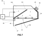
figure 7 is a schematic sectional view schematically illustrating a self-cleaning kitchen hood assembly, according to an embodiment. - . According to a general embodiment, there is provided a
kit 40 to seal close akitchen hood 100. - . As shown for example in
figure 1 , thekitchen hood 100 is preferably a self-cleaning kitchen hood, of per se known type, comprisingspray nozzles 3 mounted on afluid supply system 30 for dispensing cleaning liquid L on the internal walls of theinternal volume 1 of the self-cleaning kitchen hood 100. A filtering element supported by asupport element 101 thereof may be provided. As mentioned above, in the self-cleaning kitchen hoods of a known type, the tight-sealing closure of thelower suction mouth 102 of the kitchen hood is made with a shutter element formed byrigid slats 25 orrigid strips 25 arranged side by side. - . With reference to
figures 2 ,3A and 3B , saidkit 40 comprises aframe 42 mountable to thekitchen hood 100 and a tight-sealingfabric 46, movable on theframe 42 in at least one closing configuration to seal close thelower suction mouth 102 of thekitchen hood 100. - . The tight-sealing
fabric 46 is preferably a flexible shutter element, with a prevalent bi-dimensional extension. Said tight-sealingfabric 46 can be made of a waterproof and fireproof material. Preferably, said tight-sealingfabric 46 is made of a fabric, for example by weaving fibres, or non-woven fabric. - . The
frame 42 comprises twoopposite brackets lower suction mouth 102, creating a tight-sealingedge 54. For example, thebrackets lower mouth 102 of thekitchen hood 100, making fluid-sealing contact. For example, the brackets comprise a fixing portion which is fixed by fixing means to a wall placed behind the kitchen hood so as to make the fluid-sealing contact. - . Advantageously, said two
opposite brackets bracket - . In accordance with one embodiment, the tapering of the lower surface of the
bracket - . With further advantage, the frame comprises a
drainage 43 that extends between the twoopposite brackets drainage 43 is preferably made by means of a transverse bottom wall of theframe 42 that extends from onebracket 44L to theother bracket 44R and comprises a collection surface turned towards theinternal volume 1 of the kitchen hood 100 (i.e. substantially upwards). - . Each bracket of said two
opposite brackets element 47 for the tight-sealingfabric 46. For example, both brackets may comprise a track in which a margin of the tight-sealing fabric is inserted and which is intended to guide the movement of the fabric to reach the seal-closing configuration of thelower mouth 102 of thekitchen hood 100. - . The guiding
element 47 is directed towards thedrainage 43. In other words, the guidingelement 47 of the bracket is oriented towards thedrainage 43. For example, the guidingelement 47 is provided near or at the lower tapered surface of thebracket - . In this way, the tight-sealing
fabric 46, when in said at least one seal-closing configuration, creates a surface that slopes towards thedrainage 43 of the frame. - . In accordance with a preferred embodiment, the kit further comprises fabric movement means for moving the tight-sealing
fabric 46. - . The fabric movement means preferably comprises at least one
roller 45 to which the tight-sealingfabric 46 is mounted (wound). Theroller 45 is preferably a motorized roller, manually operable by an operator and/or automatically operable under the control of an electronic control system 55 (Figure 7 ). A fabric tensioning device to keep the tight-sealingfabric 46 taut may be provided, and for example the fabric tensioning device comprises an elastic element mounted on theroller 45. - . When in operating conditions, the
roller 45 rotating around its own axis of rotation cause the winding and/or unwinding (unfolding) of thefabric 46, which preferably has its own margin fixed to theroller 45. - . The
roller 45 is preferably controlled by thecontrol system 55 to perform a coordinated action with thespray nozzles 3. - . A sensor 56 (
Figure 7 ) may be provided to detect information on the state of closure of thelower mouth 102. In this way, thecontrol system 55 can control the actuation of theroller 45 and/or of thespray nozzles 3 based on the information acquired by thesensor 56. - . The
frame 42 preferably comprises a box-shapedbody 52 that receives saidroller 45. Unlike what is shown in the other figures, in the embodiment variant offigure 4 the box-shapedbody 52 extends substantially downwards with respect to the frame, i.e. towards the frame itself instead of outwards, so as to result, when thekit 40 is mounted to thekitchen hood 100, housed in the encumbrance of the kitchen hood itself, i.e. inside theinternal volume 1. For example, the front surface of the box-shapedbody 52 may be flush with the front surface of the casing or fairing of thekitchen hood 100. - . The guiding
element 47 extends from the box-shapedbody 52 to thedrainage 43 to seal guide the edges of the tight-sealingfabric 46 between an outlet mouth provided in the box-shapedbody 52 up to thedrainage 43 itself. In addition to the guiding elements associated with thebrackets body 52 and thedrainage 43 located in intermediate positions between thebrackets 44L, 44. The presence of the further guiding elements is particularly advantageous for supporting the tight-sealingfabric 46 in the event that the distance between thebrackets - . Referring to
figure 5 , the fabric movement means may further comprise at least one pulling device to pull the tight-sealingfabric 46 towards its seal-closing configuration. For example, the pulling device comprises an elastic element, such as for example agas spring 49. The pulling device preferably comprises an extendable element, for example telescopically extendable. The pulling device may be operable under the control of thecontrol system 55 to perform a coordinated action with theroller 45. - . With reference to
figure 6 , the fabric movement means may further comprise asecond roller 48, opposite to theroller 45 with respect to the tight-sealingfabric 46. For example, thesecond roller 48 is arranged near thedrainage 43, and for example it is housed in a box-shaped body thereof that extends from thebracket 44L to the bracket 44R. Saidsecond roller 48 is provided with elastic means suitable to bring it into rotation and/or is motorized and therefore advantageously also realizes said pulling device. - . The provision of said
frame 42 allows thekit 40 to be mounted on pre-existing kitchen hoods, allowing retrofitting on kitchen hoods of various types. - . In accordance with one aspect of the invention, a self-cleaning
kitchen hood assembly 60 for professional kitchens is provided. - . With reference to
figure 7 , the self-cleaningkitchen hood assembly 60 comprises akitchen hood 100 and a plurality ofspray nozzles 3 arranged inside theinternal volume 1 of the kitchen hood. Preferably, thespray nozzles 3 are mounted on afluid supply system 30 which supplies thenozzles 3 with cleaning liquid L. - . The self-cleaning
kitchen hood assembly 60 comprises at least onekit 40 for tight-sealing closure of a self-cleaning kitchen hood according to any one of the embodiments described above. - . The
frame 42 of the at least onekit 40 is mounted to thekitchen hood 100, preferably frontally. - . The
frame 42 preferably comprises a structure such as to leave the lowerhood suction mouth 102 open, i.e. not blocked, while defining with itswedge brackets fabric 46. - . In accordance with one embodiment, the assembly further comprises an
electronic control device 55 configured to drive thespray nozzles 3 and/or theroller 45 to move the tight-sealingfabric 46 based on information acquired by asensor 56. - . It is understood, however, that the foregoing is of exemplary and non-limiting value, therefore any variations of detail which may become necessary for technical and/or functional reasons, are considered from now on to fall within the same protective scope defined by the following claims.
Claims (8)
- Kit (40) for tight-sealing closure of a self-cleaning kitchen hood, provided with a lower suction mouth (102) comprising:- a frame (42) that can be mounted to the kitchen hood,- a tight-sealing fabric (46), movable on the frame (42) in at least one closing configuration to seal close the lower suction mouth (102) of the kitchen hood;wherein:- the frame (42) comprises two opposite brackets (44L, 44R) having a wedge body, wherein each bracket can be associated with seal closure to a respective edge portion of the lower suction mouth (102);- the frame comprises a drainage (43) that extends between the two opposite brackets (44L, 44R);- at least one bracket of said two opposite brackets with wedge body defining a guiding element (47) for the tight-sealing fabric (46) directed towards the drainage (43), in such a way that the tight-sealing fabric (46) when in said at least one seal-closing configuration, creates a surface that slopes towards the drainage (43) of the frame;- there are provided fabric movement means for moving the tight-sealing fabric, comprising at least one roller (45) to which the tight-sealing fabric is mounted;- there is provided a motor to drive the roller (45) in rotation.
- Kit according to claim 1, wherein the tight-sealing fabric (46) is made of a waterproof and fireproof material, is flexible, has a bi-dimensional extension, and is preferably made of a woven or non-woven fabric.
- Kit according to claim 4 or 5, wherein the fabric movement means further comprise a second roller (48), arranged opposite to the roller (45) with respect to the tight-sealing fabric (46) and/or at least one pulling device (49) for pulling the tight-sealing fabric.
- Kit according to any one of the preceding claims, further comprising a detecting device (54) suitable for detecting information on the configuration of the tight-sealing fabric to assess whether the tight-sealing fabric is in the closing configuration of the lower suction mouth (102).
- Kit according to any one of the preceding claims, wherein the at least one roller (45) is housed in a box-shaped body (52) that extends substantially downwards with respect to the frame (42), i.e. towards the frame (42) itself instead of outwards, so as to result, when the kit (40) is mounted to the kitchen hood (100), housed in the encumbrance of the kitchen hood itself, i.e. inside the internal volume (1) of the kitchen hood (100).
- Self-cleaning kitchen hood assembly (60) comprising:- a kitchen hood (100) with its own internal volume (1),- a plurality of spray nozzles (3) arranged within the internal volume (1),- at least one kit (40) for tight-sealing closure of a kitchen hood according to any one of the preceding claims.
- Assembly according to claim 8, further comprising an electronic control device (55) configured to drive the spray nozzles (3) and/or the roller (45) based on information detected by a detecting device (56).
- Assembly according to claim 8 or 9, wherein the frame (42) of the at least one kit is mounted to the kitchen hood (100) frontally.
Applications Claiming Priority (1)
| Application Number | Priority Date | Filing Date | Title |
|---|---|---|---|
| IT202300006174 | 2023-03-30 |
Publications (3)
| Publication Number | Publication Date |
|---|---|
| EP4438957A1 true EP4438957A1 (en) | 2024-10-02 |
| EP4438957C0 EP4438957C0 (en) | 2025-10-15 |
| EP4438957B1 EP4438957B1 (en) | 2025-10-15 |
Family
ID=86732371
Family Applications (1)
| Application Number | Title | Priority Date | Filing Date |
|---|---|---|---|
| EP24167947.1A Active EP4438957B1 (en) | 2023-03-30 | 2024-03-30 | Kit for tight-sealing closure of a self-cleaning kitchen hood |
Country Status (2)
| Country | Link |
|---|---|
| EP (1) | EP4438957B1 (en) |
| ES (1) | ES3055467T3 (en) |
Citations (4)
| Publication number | Priority date | Publication date | Assignee | Title |
|---|---|---|---|---|
| US4397226A (en) * | 1979-05-21 | 1983-08-09 | Lind Leif Ingemar | Method and device for extracting contaminated air by suction |
| DE9415799U1 (en) * | 1994-10-03 | 1994-12-22 | Bürcher, Friedrich, 82054 Sauerlach | Extractor hood |
| DE102008014283A1 (en) * | 2008-03-06 | 2009-09-10 | Blanco Cs Gmbh + Co Kg | Fume extraction device and such a comprehensive receiving device for at least one food preparation unit |
| IT201900021825A1 (en) * | 2019-11-21 | 2021-05-21 | Andrea Donzella | INTERNAL WASHING DEVICE FOR PROFESSIONAL KITCHEN EXTRACTOR HOODS |
-
2024
- 2024-03-30 EP EP24167947.1A patent/EP4438957B1/en active Active
- 2024-03-30 ES ES24167947T patent/ES3055467T3/en active Active
Patent Citations (4)
| Publication number | Priority date | Publication date | Assignee | Title |
|---|---|---|---|---|
| US4397226A (en) * | 1979-05-21 | 1983-08-09 | Lind Leif Ingemar | Method and device for extracting contaminated air by suction |
| DE9415799U1 (en) * | 1994-10-03 | 1994-12-22 | Bürcher, Friedrich, 82054 Sauerlach | Extractor hood |
| DE102008014283A1 (en) * | 2008-03-06 | 2009-09-10 | Blanco Cs Gmbh + Co Kg | Fume extraction device and such a comprehensive receiving device for at least one food preparation unit |
| IT201900021825A1 (en) * | 2019-11-21 | 2021-05-21 | Andrea Donzella | INTERNAL WASHING DEVICE FOR PROFESSIONAL KITCHEN EXTRACTOR HOODS |
Also Published As
| Publication number | Publication date |
|---|---|
| EP4438957C0 (en) | 2025-10-15 |
| EP4438957B1 (en) | 2025-10-15 |
| ES3055467T3 (en) | 2026-02-12 |
Similar Documents
| Publication | Publication Date | Title |
|---|---|---|
| KR101962730B1 (en) | Filter assembly for kitchen hood with easy changing filter | |
| US4446849A (en) | Vent apparatus for a surface cooking appliance | |
| US5662097A (en) | Stove hood with fluid filter cleaning means | |
| US6223741B1 (en) | Residential-type stove hood with fluid filter cleaning means | |
| EP3410019B1 (en) | Cooker hood and housing assembly thereof | |
| DE102015200639A1 (en) | Device for extracting exhaust air | |
| EP4438957B1 (en) | Kit for tight-sealing closure of a self-cleaning kitchen hood | |
| CN110949905B (en) | a trash can | |
| WO2017149442A1 (en) | Positive pressure vent for a vehicle | |
| US4022118A (en) | Kitchen ventilator grease extractor construction | |
| ITTO20080292A1 (en) | DOMESTIC COOKING SYSTEM INCLUDING A WALL UNIT | |
| CN114593450B (en) | Range hood curtain device, range hood and control method thereof | |
| WO2012100282A1 (en) | Cleaning indoor wall hung fan/coil units | |
| KR101578162B1 (en) | Filter assembly for kitchen hood | |
| EA021312B1 (en) | Water filter arrangement for a vacuum cleaner | |
| CN113237107B (en) | Control method of cooking device | |
| EP3128884B1 (en) | Drainage device for a cooking appliance | |
| CN110906407A (en) | Automatic opening and closing range hood and air inlet area adjusting method using same | |
| CN110681087B (en) | Fire extinguishing device and range hood with same | |
| CN214450838U (en) | Autonomous vehicle washing system | |
| EP1120607B1 (en) | Device for a heating oven provided with a door | |
| BE1016023A3 (en) | COMBINED COVER KINGS AND vent. | |
| ES2848180T3 (en) | Extractor hood and procedure for operation | |
| CN114893808A (en) | Oil box assembly for integrated cooker and integrated cooker | |
| EP4124800A1 (en) | Cooking fume extractor hood comprising a pull-out portion |
Legal Events
| Date | Code | Title | Description |
|---|---|---|---|
| PUAI | Public reference made under article 153(3) epc to a published international application that has entered the european phase |
Free format text: ORIGINAL CODE: 0009012 |
|
| STAA | Information on the status of an ep patent application or granted ep patent |
Free format text: STATUS: THE APPLICATION HAS BEEN PUBLISHED |
|
| AK | Designated contracting states |
Kind code of ref document: A1 Designated state(s): AL AT BE BG CH CY CZ DE DK EE ES FI FR GB GR HR HU IE IS IT LI LT LU LV MC ME MK MT NL NO PL PT RO RS SE SI SK SM TR |
|
| STAA | Information on the status of an ep patent application or granted ep patent |
Free format text: STATUS: REQUEST FOR EXAMINATION WAS MADE |
|
| 17P | Request for examination filed |
Effective date: 20250327 |
|
| GRAP | Despatch of communication of intention to grant a patent |
Free format text: ORIGINAL CODE: EPIDOSNIGR1 |
|
| STAA | Information on the status of an ep patent application or granted ep patent |
Free format text: STATUS: GRANT OF PATENT IS INTENDED |
|
| RIC1 | Information provided on ipc code assigned before grant |
Ipc: B08B 15/02 20060101ALI20250416BHEP Ipc: F24C 15/20 20060101AFI20250416BHEP |
|
| INTG | Intention to grant announced |
Effective date: 20250509 |
|
| GRAS | Grant fee paid |
Free format text: ORIGINAL CODE: EPIDOSNIGR3 |
|
| GRAA | (expected) grant |
Free format text: ORIGINAL CODE: 0009210 |
|
| STAA | Information on the status of an ep patent application or granted ep patent |
Free format text: STATUS: THE PATENT HAS BEEN GRANTED |
|
| AK | Designated contracting states |
Kind code of ref document: B1 Designated state(s): AL AT BE BG CH CY CZ DE DK EE ES FI FR GB GR HR HU IE IS IT LI LT LU LV MC ME MK MT NL NO PL PT RO RS SE SI SK SM TR |
|
| REG | Reference to a national code |
Ref country code: GB Ref legal event code: FG4D Ref country code: CH Ref legal event code: F10 Free format text: ST27 STATUS EVENT CODE: U-0-0-F10-F00 (AS PROVIDED BY THE NATIONAL OFFICE) Effective date: 20251015 |
|
| REG | Reference to a national code |
Ref country code: DE Ref legal event code: R096 Ref document number: 602024000916 Country of ref document: DE |
|
| REG | Reference to a national code |
Ref country code: IE Ref legal event code: FG4D |
|
| U01 | Request for unitary effect filed |
Effective date: 20251113 |
|
| U07 | Unitary effect registered |
Designated state(s): AT BE BG DE DK EE FI FR IT LT LU LV MT NL PT RO SE SI Effective date: 20251118 |
|
| REG | Reference to a national code |
Ref country code: ES Ref legal event code: FG2A Ref document number: 3055467 Country of ref document: ES Kind code of ref document: T3 Effective date: 20260212 |
|
| PG25 | Lapsed in a contracting state [announced via postgrant information from national office to epo] |
Ref country code: NO Free format text: LAPSE BECAUSE OF FAILURE TO SUBMIT A TRANSLATION OF THE DESCRIPTION OR TO PAY THE FEE WITHIN THE PRESCRIBED TIME-LIMIT Effective date: 20260115 |
|
| PG25 | Lapsed in a contracting state [announced via postgrant information from national office to epo] |
Ref country code: HR Free format text: LAPSE BECAUSE OF FAILURE TO SUBMIT A TRANSLATION OF THE DESCRIPTION OR TO PAY THE FEE WITHIN THE PRESCRIBED TIME-LIMIT Effective date: 20251015 |
|
| PG25 | Lapsed in a contracting state [announced via postgrant information from national office to epo] |
Ref country code: RS Free format text: LAPSE BECAUSE OF FAILURE TO SUBMIT A TRANSLATION OF THE DESCRIPTION OR TO PAY THE FEE WITHIN THE PRESCRIBED TIME-LIMIT Effective date: 20260115 |
|
| PG25 | Lapsed in a contracting state [announced via postgrant information from national office to epo] |
Ref country code: IS Free format text: LAPSE BECAUSE OF FAILURE TO SUBMIT A TRANSLATION OF THE DESCRIPTION OR TO PAY THE FEE WITHIN THE PRESCRIBED TIME-LIMIT Effective date: 20260215 |
|
| PG25 | Lapsed in a contracting state [announced via postgrant information from national office to epo] |
Ref country code: PL Free format text: LAPSE BECAUSE OF FAILURE TO SUBMIT A TRANSLATION OF THE DESCRIPTION OR TO PAY THE FEE WITHIN THE PRESCRIBED TIME-LIMIT Effective date: 20251015 |
|
| U20 | Renewal fee for the european patent with unitary effect paid |
Year of fee payment: 3 Effective date: 20260323 |