EP4438940A1 - Hydrogen re-liquefaction system - Google Patents
Hydrogen re-liquefaction system Download PDFInfo
- Publication number
- EP4438940A1 EP4438940A1 EP22898388.8A EP22898388A EP4438940A1 EP 4438940 A1 EP4438940 A1 EP 4438940A1 EP 22898388 A EP22898388 A EP 22898388A EP 4438940 A1 EP4438940 A1 EP 4438940A1
- Authority
- EP
- European Patent Office
- Prior art keywords
- liquefaction
- gas
- passage
- boil
- hydrogen
- Prior art date
- Legal status (The legal status is an assumption and is not a legal conclusion. Google has not performed a legal analysis and makes no representation as to the accuracy of the status listed.)
- Pending
Links
Images

Classifications
-
- F—MECHANICAL ENGINEERING; LIGHTING; HEATING; WEAPONS; BLASTING
- F25—REFRIGERATION OR COOLING; COMBINED HEATING AND REFRIGERATION SYSTEMS; HEAT PUMP SYSTEMS; MANUFACTURE OR STORAGE OF ICE; LIQUEFACTION SOLIDIFICATION OF GASES
- F25J—LIQUEFACTION, SOLIDIFICATION OR SEPARATION OF GASES OR GASEOUS OR LIQUEFIED GASEOUS MIXTURES BY PRESSURE AND COLD TREATMENT OR BY BRINGING THEM INTO THE SUPERCRITICAL STATE
- F25J1/00—Processes or apparatus for liquefying or solidifying gases or gaseous mixtures
- F25J1/0002—Processes or apparatus for liquefying or solidifying gases or gaseous mixtures characterised by the fluid to be liquefied
- F25J1/0005—Light or noble gases
- F25J1/001—Hydrogen
-
- F—MECHANICAL ENGINEERING; LIGHTING; HEATING; WEAPONS; BLASTING
- F17—STORING OR DISTRIBUTING GASES OR LIQUIDS
- F17C—VESSELS FOR CONTAINING OR STORING COMPRESSED, LIQUEFIED OR SOLIDIFIED GASES; FIXED-CAPACITY GAS-HOLDERS; FILLING VESSELS WITH, OR DISCHARGING FROM VESSELS, COMPRESSED, LIQUEFIED, OR SOLIDIFIED GASES
- F17C13/00—Details of vessels or of the filling or discharging of vessels
- F17C13/004—Details of vessels or of the filling or discharging of vessels for large storage vessels not under pressure
-
- F—MECHANICAL ENGINEERING; LIGHTING; HEATING; WEAPONS; BLASTING
- F17—STORING OR DISTRIBUTING GASES OR LIQUIDS
- F17C—VESSELS FOR CONTAINING OR STORING COMPRESSED, LIQUEFIED OR SOLIDIFIED GASES; FIXED-CAPACITY GAS-HOLDERS; FILLING VESSELS WITH, OR DISCHARGING FROM VESSELS, COMPRESSED, LIQUEFIED, OR SOLIDIFIED GASES
- F17C13/00—Details of vessels or of the filling or discharging of vessels
- F17C13/005—Details of vessels or of the filling or discharging of vessels for medium-size and small storage vessels not under pressure
-
- F—MECHANICAL ENGINEERING; LIGHTING; HEATING; WEAPONS; BLASTING
- F17—STORING OR DISTRIBUTING GASES OR LIQUIDS
- F17C—VESSELS FOR CONTAINING OR STORING COMPRESSED, LIQUEFIED OR SOLIDIFIED GASES; FIXED-CAPACITY GAS-HOLDERS; FILLING VESSELS WITH, OR DISCHARGING FROM VESSELS, COMPRESSED, LIQUEFIED, OR SOLIDIFIED GASES
- F17C9/00—Methods or apparatus for discharging liquefied or solidified gases from vessels not under pressure
- F17C9/02—Methods or apparatus for discharging liquefied or solidified gases from vessels not under pressure with change of state, e.g. vaporisation
-
- F—MECHANICAL ENGINEERING; LIGHTING; HEATING; WEAPONS; BLASTING
- F25—REFRIGERATION OR COOLING; COMBINED HEATING AND REFRIGERATION SYSTEMS; HEAT PUMP SYSTEMS; MANUFACTURE OR STORAGE OF ICE; LIQUEFACTION SOLIDIFICATION OF GASES
- F25J—LIQUEFACTION, SOLIDIFICATION OR SEPARATION OF GASES OR GASEOUS OR LIQUEFIED GASEOUS MIXTURES BY PRESSURE AND COLD TREATMENT OR BY BRINGING THEM INTO THE SUPERCRITICAL STATE
- F25J1/00—Processes or apparatus for liquefying or solidifying gases or gaseous mixtures
- F25J1/02—Processes or apparatus for liquefying or solidifying gases or gaseous mixtures requiring the use of refrigeration, e.g. of helium or hydrogen ; Details and kind of the refrigeration system used; Integration with other units or processes; Controlling aspects of the process
- F25J1/0201—Processes or apparatus for liquefying or solidifying gases or gaseous mixtures requiring the use of refrigeration, e.g. of helium or hydrogen ; Details and kind of the refrigeration system used; Integration with other units or processes; Controlling aspects of the process using only internal refrigeration means, i.e. without external refrigeration
-
- F—MECHANICAL ENGINEERING; LIGHTING; HEATING; WEAPONS; BLASTING
- F25—REFRIGERATION OR COOLING; COMBINED HEATING AND REFRIGERATION SYSTEMS; HEAT PUMP SYSTEMS; MANUFACTURE OR STORAGE OF ICE; LIQUEFACTION SOLIDIFICATION OF GASES
- F25J—LIQUEFACTION, SOLIDIFICATION OR SEPARATION OF GASES OR GASEOUS OR LIQUEFIED GASEOUS MIXTURES BY PRESSURE AND COLD TREATMENT OR BY BRINGING THEM INTO THE SUPERCRITICAL STATE
- F25J1/00—Processes or apparatus for liquefying or solidifying gases or gaseous mixtures
- F25J1/02—Processes or apparatus for liquefying or solidifying gases or gaseous mixtures requiring the use of refrigeration, e.g. of helium or hydrogen ; Details and kind of the refrigeration system used; Integration with other units or processes; Controlling aspects of the process
- F25J1/0225—Processes or apparatus for liquefying or solidifying gases or gaseous mixtures requiring the use of refrigeration, e.g. of helium or hydrogen ; Details and kind of the refrigeration system used; Integration with other units or processes; Controlling aspects of the process using other external refrigeration means not provided before, e.g. heat driven absorption chillers
-
- F—MECHANICAL ENGINEERING; LIGHTING; HEATING; WEAPONS; BLASTING
- F25—REFRIGERATION OR COOLING; COMBINED HEATING AND REFRIGERATION SYSTEMS; HEAT PUMP SYSTEMS; MANUFACTURE OR STORAGE OF ICE; LIQUEFACTION SOLIDIFICATION OF GASES
- F25J—LIQUEFACTION, SOLIDIFICATION OR SEPARATION OF GASES OR GASEOUS OR LIQUEFIED GASEOUS MIXTURES BY PRESSURE AND COLD TREATMENT OR BY BRINGING THEM INTO THE SUPERCRITICAL STATE
- F25J1/00—Processes or apparatus for liquefying or solidifying gases or gaseous mixtures
- F25J1/02—Processes or apparatus for liquefying or solidifying gases or gaseous mixtures requiring the use of refrigeration, e.g. of helium or hydrogen ; Details and kind of the refrigeration system used; Integration with other units or processes; Controlling aspects of the process
- F25J1/0243—Start-up or control of the process; Details of the apparatus used; Details of the refrigerant compression system used
- F25J1/0257—Construction and layout of liquefaction equipments, e.g. valves, machines
- F25J1/0262—Details of the cold heat exchange system
- F25J1/0264—Arrangement of heat exchanger cores in parallel with different functions, e.g. different cooling streams
- F25J1/0265—Arrangement of heat exchanger cores in parallel with different functions, e.g. different cooling streams comprising cores associated exclusively with the cooling of a refrigerant stream, e.g. for auto-refrigeration or economizer
- F25J1/0267—Arrangement of heat exchanger cores in parallel with different functions, e.g. different cooling streams comprising cores associated exclusively with the cooling of a refrigerant stream, e.g. for auto-refrigeration or economizer using flash gas as heat sink
-
- F—MECHANICAL ENGINEERING; LIGHTING; HEATING; WEAPONS; BLASTING
- F17—STORING OR DISTRIBUTING GASES OR LIQUIDS
- F17C—VESSELS FOR CONTAINING OR STORING COMPRESSED, LIQUEFIED OR SOLIDIFIED GASES; FIXED-CAPACITY GAS-HOLDERS; FILLING VESSELS WITH, OR DISCHARGING FROM VESSELS, COMPRESSED, LIQUEFIED, OR SOLIDIFIED GASES
- F17C2221/00—Handled fluid, in particular type of fluid
- F17C2221/01—Pure fluids
- F17C2221/012—Hydrogen
-
- F—MECHANICAL ENGINEERING; LIGHTING; HEATING; WEAPONS; BLASTING
- F17—STORING OR DISTRIBUTING GASES OR LIQUIDS
- F17C—VESSELS FOR CONTAINING OR STORING COMPRESSED, LIQUEFIED OR SOLIDIFIED GASES; FIXED-CAPACITY GAS-HOLDERS; FILLING VESSELS WITH, OR DISCHARGING FROM VESSELS, COMPRESSED, LIQUEFIED, OR SOLIDIFIED GASES
- F17C2223/00—Handled fluid before transfer, i.e. state of fluid when stored in the vessel or before transfer from the vessel
- F17C2223/01—Handled fluid before transfer, i.e. state of fluid when stored in the vessel or before transfer from the vessel characterised by the phase
- F17C2223/0107—Single phase
- F17C2223/013—Single phase liquid
-
- F—MECHANICAL ENGINEERING; LIGHTING; HEATING; WEAPONS; BLASTING
- F17—STORING OR DISTRIBUTING GASES OR LIQUIDS
- F17C—VESSELS FOR CONTAINING OR STORING COMPRESSED, LIQUEFIED OR SOLIDIFIED GASES; FIXED-CAPACITY GAS-HOLDERS; FILLING VESSELS WITH, OR DISCHARGING FROM VESSELS, COMPRESSED, LIQUEFIED, OR SOLIDIFIED GASES
- F17C2223/00—Handled fluid before transfer, i.e. state of fluid when stored in the vessel or before transfer from the vessel
- F17C2223/01—Handled fluid before transfer, i.e. state of fluid when stored in the vessel or before transfer from the vessel characterised by the phase
- F17C2223/0146—Two-phase
- F17C2223/0153—Liquefied gas, e.g. LPG, GPL
- F17C2223/0161—Liquefied gas, e.g. LPG, GPL cryogenic, e.g. LNG, GNL, PLNG
-
- F—MECHANICAL ENGINEERING; LIGHTING; HEATING; WEAPONS; BLASTING
- F17—STORING OR DISTRIBUTING GASES OR LIQUIDS
- F17C—VESSELS FOR CONTAINING OR STORING COMPRESSED, LIQUEFIED OR SOLIDIFIED GASES; FIXED-CAPACITY GAS-HOLDERS; FILLING VESSELS WITH, OR DISCHARGING FROM VESSELS, COMPRESSED, LIQUEFIED, OR SOLIDIFIED GASES
- F17C2223/00—Handled fluid before transfer, i.e. state of fluid when stored in the vessel or before transfer from the vessel
- F17C2223/03—Handled fluid before transfer, i.e. state of fluid when stored in the vessel or before transfer from the vessel characterised by the pressure level
- F17C2223/033—Small pressure, e.g. for liquefied gas
-
- F—MECHANICAL ENGINEERING; LIGHTING; HEATING; WEAPONS; BLASTING
- F17—STORING OR DISTRIBUTING GASES OR LIQUIDS
- F17C—VESSELS FOR CONTAINING OR STORING COMPRESSED, LIQUEFIED OR SOLIDIFIED GASES; FIXED-CAPACITY GAS-HOLDERS; FILLING VESSELS WITH, OR DISCHARGING FROM VESSELS, COMPRESSED, LIQUEFIED, OR SOLIDIFIED GASES
- F17C2223/00—Handled fluid before transfer, i.e. state of fluid when stored in the vessel or before transfer from the vessel
- F17C2223/04—Handled fluid before transfer, i.e. state of fluid when stored in the vessel or before transfer from the vessel characterised by other properties of handled fluid before transfer
- F17C2223/042—Localisation of the removal point
- F17C2223/043—Localisation of the removal point in the gas
-
- F—MECHANICAL ENGINEERING; LIGHTING; HEATING; WEAPONS; BLASTING
- F17—STORING OR DISTRIBUTING GASES OR LIQUIDS
- F17C—VESSELS FOR CONTAINING OR STORING COMPRESSED, LIQUEFIED OR SOLIDIFIED GASES; FIXED-CAPACITY GAS-HOLDERS; FILLING VESSELS WITH, OR DISCHARGING FROM VESSELS, COMPRESSED, LIQUEFIED, OR SOLIDIFIED GASES
- F17C2223/00—Handled fluid before transfer, i.e. state of fluid when stored in the vessel or before transfer from the vessel
- F17C2223/04—Handled fluid before transfer, i.e. state of fluid when stored in the vessel or before transfer from the vessel characterised by other properties of handled fluid before transfer
- F17C2223/042—Localisation of the removal point
- F17C2223/046—Localisation of the removal point in the liquid
-
- F—MECHANICAL ENGINEERING; LIGHTING; HEATING; WEAPONS; BLASTING
- F17—STORING OR DISTRIBUTING GASES OR LIQUIDS
- F17C—VESSELS FOR CONTAINING OR STORING COMPRESSED, LIQUEFIED OR SOLIDIFIED GASES; FIXED-CAPACITY GAS-HOLDERS; FILLING VESSELS WITH, OR DISCHARGING FROM VESSELS, COMPRESSED, LIQUEFIED, OR SOLIDIFIED GASES
- F17C2225/00—Handled fluid after transfer, i.e. state of fluid after transfer from the vessel
- F17C2225/01—Handled fluid after transfer, i.e. state of fluid after transfer from the vessel characterised by the phase
- F17C2225/0107—Single phase
- F17C2225/013—Single phase liquid
-
- F—MECHANICAL ENGINEERING; LIGHTING; HEATING; WEAPONS; BLASTING
- F17—STORING OR DISTRIBUTING GASES OR LIQUIDS
- F17C—VESSELS FOR CONTAINING OR STORING COMPRESSED, LIQUEFIED OR SOLIDIFIED GASES; FIXED-CAPACITY GAS-HOLDERS; FILLING VESSELS WITH, OR DISCHARGING FROM VESSELS, COMPRESSED, LIQUEFIED, OR SOLIDIFIED GASES
- F17C2227/00—Transfer of fluids, i.e. method or means for transferring the fluid; Heat exchange with the fluid
- F17C2227/03—Heat exchange with the fluid
- F17C2227/0302—Heat exchange with the fluid by heating
- F17C2227/0304—Heat exchange with the fluid by heating using an electric heater
-
- F—MECHANICAL ENGINEERING; LIGHTING; HEATING; WEAPONS; BLASTING
- F17—STORING OR DISTRIBUTING GASES OR LIQUIDS
- F17C—VESSELS FOR CONTAINING OR STORING COMPRESSED, LIQUEFIED OR SOLIDIFIED GASES; FIXED-CAPACITY GAS-HOLDERS; FILLING VESSELS WITH, OR DISCHARGING FROM VESSELS, COMPRESSED, LIQUEFIED, OR SOLIDIFIED GASES
- F17C2227/00—Transfer of fluids, i.e. method or means for transferring the fluid; Heat exchange with the fluid
- F17C2227/03—Heat exchange with the fluid
- F17C2227/0337—Heat exchange with the fluid by cooling
-
- F—MECHANICAL ENGINEERING; LIGHTING; HEATING; WEAPONS; BLASTING
- F17—STORING OR DISTRIBUTING GASES OR LIQUIDS
- F17C—VESSELS FOR CONTAINING OR STORING COMPRESSED, LIQUEFIED OR SOLIDIFIED GASES; FIXED-CAPACITY GAS-HOLDERS; FILLING VESSELS WITH, OR DISCHARGING FROM VESSELS, COMPRESSED, LIQUEFIED, OR SOLIDIFIED GASES
- F17C2265/00—Effects achieved by gas storage or gas handling
- F17C2265/03—Treating the boil-off
- F17C2265/032—Treating the boil-off by recovery
- F17C2265/033—Treating the boil-off by recovery with cooling
-
- F—MECHANICAL ENGINEERING; LIGHTING; HEATING; WEAPONS; BLASTING
- F17—STORING OR DISTRIBUTING GASES OR LIQUIDS
- F17C—VESSELS FOR CONTAINING OR STORING COMPRESSED, LIQUEFIED OR SOLIDIFIED GASES; FIXED-CAPACITY GAS-HOLDERS; FILLING VESSELS WITH, OR DISCHARGING FROM VESSELS, COMPRESSED, LIQUEFIED, OR SOLIDIFIED GASES
- F17C2265/00—Effects achieved by gas storage or gas handling
- F17C2265/03—Treating the boil-off
- F17C2265/032—Treating the boil-off by recovery
- F17C2265/037—Treating the boil-off by recovery with pressurising
-
- F—MECHANICAL ENGINEERING; LIGHTING; HEATING; WEAPONS; BLASTING
- F25—REFRIGERATION OR COOLING; COMBINED HEATING AND REFRIGERATION SYSTEMS; HEAT PUMP SYSTEMS; MANUFACTURE OR STORAGE OF ICE; LIQUEFACTION SOLIDIFICATION OF GASES
- F25J—LIQUEFACTION, SOLIDIFICATION OR SEPARATION OF GASES OR GASEOUS OR LIQUEFIED GASEOUS MIXTURES BY PRESSURE AND COLD TREATMENT OR BY BRINGING THEM INTO THE SUPERCRITICAL STATE
- F25J2210/00—Processes characterised by the type or other details of the feed stream
- F25J2210/90—Boil-off gas from storage
-
- F—MECHANICAL ENGINEERING; LIGHTING; HEATING; WEAPONS; BLASTING
- F25—REFRIGERATION OR COOLING; COMBINED HEATING AND REFRIGERATION SYSTEMS; HEAT PUMP SYSTEMS; MANUFACTURE OR STORAGE OF ICE; LIQUEFACTION SOLIDIFICATION OF GASES
- F25J—LIQUEFACTION, SOLIDIFICATION OR SEPARATION OF GASES OR GASEOUS OR LIQUEFIED GASEOUS MIXTURES BY PRESSURE AND COLD TREATMENT OR BY BRINGING THEM INTO THE SUPERCRITICAL STATE
- F25J2230/00—Processes or apparatus involving steps for increasing the pressure of gaseous process streams
- F25J2230/08—Cold compressor, i.e. suction of the gas at cryogenic temperature and generally without afterstage-cooler
-
- F—MECHANICAL ENGINEERING; LIGHTING; HEATING; WEAPONS; BLASTING
- F25—REFRIGERATION OR COOLING; COMBINED HEATING AND REFRIGERATION SYSTEMS; HEAT PUMP SYSTEMS; MANUFACTURE OR STORAGE OF ICE; LIQUEFACTION SOLIDIFICATION OF GASES
- F25J—LIQUEFACTION, SOLIDIFICATION OR SEPARATION OF GASES OR GASEOUS OR LIQUEFIED GASEOUS MIXTURES BY PRESSURE AND COLD TREATMENT OR BY BRINGING THEM INTO THE SUPERCRITICAL STATE
- F25J2230/00—Processes or apparatus involving steps for increasing the pressure of gaseous process streams
- F25J2230/30—Compression of the feed stream
-
- F—MECHANICAL ENGINEERING; LIGHTING; HEATING; WEAPONS; BLASTING
- F25—REFRIGERATION OR COOLING; COMBINED HEATING AND REFRIGERATION SYSTEMS; HEAT PUMP SYSTEMS; MANUFACTURE OR STORAGE OF ICE; LIQUEFACTION SOLIDIFICATION OF GASES
- F25J—LIQUEFACTION, SOLIDIFICATION OR SEPARATION OF GASES OR GASEOUS OR LIQUEFIED GASEOUS MIXTURES BY PRESSURE AND COLD TREATMENT OR BY BRINGING THEM INTO THE SUPERCRITICAL STATE
- F25J2270/00—Refrigeration techniques used
- F25J2270/02—Internal refrigeration with liquid vaporising loop
-
- F—MECHANICAL ENGINEERING; LIGHTING; HEATING; WEAPONS; BLASTING
- F25—REFRIGERATION OR COOLING; COMBINED HEATING AND REFRIGERATION SYSTEMS; HEAT PUMP SYSTEMS; MANUFACTURE OR STORAGE OF ICE; LIQUEFACTION SOLIDIFICATION OF GASES
- F25J—LIQUEFACTION, SOLIDIFICATION OR SEPARATION OF GASES OR GASEOUS OR LIQUEFIED GASEOUS MIXTURES BY PRESSURE AND COLD TREATMENT OR BY BRINGING THEM INTO THE SUPERCRITICAL STATE
- F25J2270/00—Refrigeration techniques used
- F25J2270/08—Internal refrigeration by flash gas recovery loop
-
- F—MECHANICAL ENGINEERING; LIGHTING; HEATING; WEAPONS; BLASTING
- F25—REFRIGERATION OR COOLING; COMBINED HEATING AND REFRIGERATION SYSTEMS; HEAT PUMP SYSTEMS; MANUFACTURE OR STORAGE OF ICE; LIQUEFACTION SOLIDIFICATION OF GASES
- F25J—LIQUEFACTION, SOLIDIFICATION OR SEPARATION OF GASES OR GASEOUS OR LIQUEFIED GASEOUS MIXTURES BY PRESSURE AND COLD TREATMENT OR BY BRINGING THEM INTO THE SUPERCRITICAL STATE
- F25J2270/00—Refrigeration techniques used
- F25J2270/90—External refrigeration, e.g. conventional closed-loop mechanical refrigeration unit using Freon or NH3, unspecified external refrigeration
- F25J2270/908—External refrigeration, e.g. conventional closed-loop mechanical refrigeration unit using Freon or NH3, unspecified external refrigeration by regenerative chillers, i.e. oscillating or dynamic systems, e.g. Stirling refrigerator, thermoelectric ("Peltier") or magnetic refrigeration
-
- Y—GENERAL TAGGING OF NEW TECHNOLOGICAL DEVELOPMENTS; GENERAL TAGGING OF CROSS-SECTIONAL TECHNOLOGIES SPANNING OVER SEVERAL SECTIONS OF THE IPC; TECHNICAL SUBJECTS COVERED BY FORMER USPC CROSS-REFERENCE ART COLLECTIONS [XRACs] AND DIGESTS
- Y02—TECHNOLOGIES OR APPLICATIONS FOR MITIGATION OR ADAPTATION AGAINST CLIMATE CHANGE
- Y02E—REDUCTION OF GREENHOUSE GAS [GHG] EMISSIONS, RELATED TO ENERGY GENERATION, TRANSMISSION OR DISTRIBUTION
- Y02E60/00—Enabling technologies; Technologies with a potential or indirect contribution to GHG emissions mitigation
- Y02E60/30—Hydrogen technology
- Y02E60/32—Hydrogen storage
Definitions
- the present invention relates to a hydrogen re-liquefaction system that re-liquefies boil-off gas produced in a liquid hydrogen tank into liquid hydrogen and returns the liquid hydrogen to the liquid hydrogen tank.
- re-liquefaction systems that re-liquefy boil-off gas produced in a liquid hydrogen tank in which liquefied, low-temperature gas is stored.
- One known example of the re-liquefaction systems is the liquefied, low-temperature gas reservoir system disclosed in Patent Literature (PTL) 1.
- PTL Patent Literature 1
- boil-off gas is compressed first. Subsequently, heat is exchanged between the compressed boil-off gas and gas to be delivered. Furthermore, the compressed boil-off gas is expanded using an expansion valve, and thus the boil-off gas is re-liquefied.
- the boil-off gas is compressed and cooled. Furthermore, the compressed and cooled boil-off gas is expanded, and thus the boil-off gas is liquefied. Therefore, the efficiency of the re-liquefaction of the boil-off gas by the liquefied, low-temperature gas reservoir system is low.
- an object of the present invention is to provide a hydrogen re-liquefaction system capable of re-liquefying boil-off gas with higher efficiency.
- a hydrogen re-liquefaction system is a hydrogen re-liquefaction system that re-liquefies boil-off gas produced in a liquid hydrogen tank into liquid hydrogen and returns the liquid hydrogen to the liquid hydrogen tank, and includes: a delivery passage through which hydrogen to be delivered from the liquid hydrogen tank to a supply destination flows; a re-liquefaction passage through which the boil-off gas flows; and a re-liquefaction device that cools the boil-off gas flowing through the re-liquefaction passage and condenses the boil-off gas, wherein: the re-liquefaction device is a magnetic refrigerator that includes: a condenser provided in the re-liquefaction passage; and a heat dissipator provided in the delivery passage, cools the boil-off gas via the condenser by demagnetization, and releases heat generated during magnetization to hydrogen via the heat dissipator.
- a condenser provided in the re-liquefaction passage and a heat dissipator provided in the delivery passage. Therefore, as a result of heat dissipation to the delivery passage which has an extremely low temperature relative to the temperature of the atmosphere, a magnetic refrigerator having a narrow operating temperature range can be applied to a re-liquefaction device.
- the magnetic refrigerator can cool boil-off gas and release heat to hydrogen by switching between demagnetization and magnetization.
- the use of such a magnetic refrigerator in a re-liquefaction device allows for removal of devices such as a compressor included in a gas type refrigerator. Therefore, in the re-liquefaction device, there is no need to drive a compressor or the like.
- the re-liquefaction device can perform re-liquefaction with higher efficiency than a gas refrigeration type re-liquefaction device.
- boil-off gas can be re-liquefied with higher efficiency.
- re-liquefaction systems hydrogen re-liquefaction systems (hereinafter referred to simply as "re-liquefaction systems") 1, 1A according to Embodiments 1, 2 of the present invention will be described with reference to the aforementioned drawings.
- re-liquefaction systems hydrogen re-liquefaction systems
- 1A hydrogen re-liquefaction systems
- the concept of directions mentioned in the following description is used for the sake of explanation; the orientations, etc., of elements according to the invention are not limited to these directions.
- Each of the re-liquefaction systems 1, 1A described below is merely one embodiment of the present invention.
- the present invention is not limited to the embodiments and may be subject to addition, deletion, and alteration within the scope of the essence of the invention.
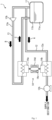
- a re-liquefaction system 1 illustrated in Fig. 1 is provided in a liquid hydrogen storage facility where liquid hydrogen is stored.
- the re-liquefaction system 1 includes a liquid hydrogen tank 11.
- liquefied hydrogen that is, liquid hydrogen
- the re-liquefaction system 1 re-liquefies the boil-off gas produced in the liquid hydrogen tank 11.
- the re-liquefaction system 1 returns, to the liquid hydrogen tank 11, liquid hydrogen produced by re-liquefaction.
- the re-liquefaction system 1 includes a gas delivery passage 12, a re-liquefaction passage 13, and a re-liquefaction device 14, in addition to said liquid hydrogen tank 11.
- the liquid hydrogen tank 11 is a container in which liquid hydrogen is stored as mentioned earlier.
- the liquid hydrogen tank 11 includes a vacuum insulation structure. Note that the liquid hydrogen tank 11 does not necessarily need to include the vacuum insulation structure. With the vacuum insulation structure, the inside of the liquid hydrogen tank 11 is maintained at a temperature lower than or equal to the saturation temperature of hydrogen. Meanwhile, in the liquid hydrogen tank 11, a portion of the liquid hydrogen is evaporated and thus boil-off gas is produced as mentioned earlier. Therefore, in the liquid hydrogen tank 11, the liquid hydrogen is stored in a lower space 11a, and the boil-off gas is stored in an upper space 11b.
- the gas delivery passage 12 is a passage through which hydrogen to be delivered from the liquid hydrogen tank 11 to a supply destination flows.
- the hydrogen to be delivered is the boil-off gas (hereinafter referred to as "delivery gas"). More specifically, one end of the gas delivery passage 12 is connected to the liquid hydrogen tank 11. In the present embodiment, one end of the gas delivery passage 12 is connected to the upper space 11b of the liquid hydrogen tank 11. Meanwhile, the other end of the gas delivery passage 12 is connected to a supply destination.
- the supply destination is a hydrogen consuming device such as a power generator and a hydrogen engine and a facility including the hydrogen consuming device. Note that the supply destination is not limited to the hydrogen consuming device and the facility including the hydrogen consuming device.
- the gas delivery passage 12 includes an insulation structure 12a and a compressor 12b.
- the insulation structure 12a which is one example of the first insulation structure, shuts off the heat input to the boil-off gas flowing through the gas delivery passage 12.
- the boil-off gas flowing through the gas delivery passage 12 is maintained at a temperature that is extremely low (that is close to the saturation temperature of hydrogen in the present embodiment) as with the internal temperature of the liquid hydrogen tank.
- the insulation structure 12a is a vacuum insulation pipe structure, for example.
- the compressor 12b compresses the delivery gas. More specifically, the compressor 12b compresses the boil-off gas at a pressure required at the supply destination. Subsequently, the compressor 12b sends the delivery gas to the supply destination.
- the re-liquefaction passage 13 allows the boil-off gas to flow therein. More specifically, the re-liquefaction passage 13 allows the passage of the boil-off gas to be re-liquefied. Furthermore, the re-liquefaction passage 13 returns, to the liquid hydrogen tank 11, the liquid hydrogen obtained by the re-liquefication. More specifically, both ends of the re-liquefaction passage 13 are connected to the liquid hydrogen tank 11. To describe in more detail, both ends of the re-liquefaction passage 13 are connected to the upper space 11b of the liquid hydrogen tank 11. Note that in the present embodiment, one end of the re-liquefaction passage 13 is connected to the gas delivery passage 12. The one end of the re-liquefaction passage 13 is connected to the upper space 11b of the liquid hydrogen tank 11 via the gas delivery passage 12.
- the re-liquefaction passage 13 includes an insulation structure 13a and a blower 13b.
- the insulation structure 13a which is one example of the second insulation structure, shuts off the heat input to the boil-off gas flowing through the re-liquefaction passage 13.
- the boil-off gas flowing through the re-liquefaction passage 13 is maintained at a temperature that is extremely low (that is close to the saturation temperature of hydrogen in the present embodiment) as with the internal temperature of the liquid hydrogen tank.
- the insulation structure 13a is a vacuum insulation pipe structure, for example.
- the blower 13b draws the boil-off gas from the liquid hydrogen tank 11.
- blower 13b draws, into re-liquefaction passage 13, a portion of the boil-off gas brought from the upper space 11b of the liquid hydrogen tank 11 to the gas delivery passage 12. Subsequently, blower 13b sends the boil-off gas to an area located downstream of the blower 13b in the re-liquefaction passage 13.
- the re-liquefaction device 14 cools the boil-off gas flowing through the re-liquefaction passage 13. By cooling the boil-off gas, the re-liquefaction device 14 condenses the boil-off gas into liquid hydrogen. More specifically, the re-liquefaction device 14 cools the boil-off gas flowing through the re-liquefaction passage 13 to a temperature lower than or equal to the saturation temperature of hydrogen. As a result, at least a portion of the boil-off gas flowing through the re-liquefaction passage 13 is condensed into liquid hydrogen.
- the re-liquefaction device 14 including such a function is a magnetic refrigerator. Next, the re-liquefaction device 14, which is a magnetic refrigerator, will be described in further detail.
- the re-liquefaction device 14 includes a condenser 14a and a heat dissipator 14b.
- the condenser 14a is provided in the re-liquefaction passage 13. More specifically, the condenser 14a is disposed on the downstream side of the blower 13b in the re-liquefaction passage 13.
- the re-liquefaction device 14 cools the boil-off gas via the condenser 14a by demagnetization.
- the heat dissipator 14b is provided in the gas delivery passage 12. More specifically, in the gas delivery passage 12, the heat dissipator 14b is disposed closer to the supply destination side than the re-liquefaction passage 13 is. Subsequently, the re-liquefaction device 14 releases heat generated during magnetization to hydrogen via the heat dissipator 14b.
- the re-liquefaction device 14 is configured as follows, for example. Note that the following example is one example of the configuration of the re-liquefaction device 14. Therefore, the re-liquefaction device 14 is not limited to being configured as follows. Specifically, it is sufficient that the re-liquefaction device 14 be configured to be able to cool the boil-off gas by demagnetization and release the heat generated during magnetization to the delivery gas as described earlier.
- the re-liquefaction device 14 further includes a heat medium 14c and a magnetic field generator 14d, for example.
- the heat medium 14c is made from a magnetic material. The heat medium 14c is cooled by demagnetization and generates heat by magnetization.
- the magnetic field generator 14d produces a magnetic field around the heat medium 14c and thereby magnetizes the heat medium 14c. Furthermore, the magnetic field generator 14d demagnetizes the heat medium 14c by removing the magnetic field around the heat medium 14c.
- the magnetic field generator 14d is a coil or a permanent magnet, for example. In the case where the magnetic field generator 14d is a coil, the magnetic field generator 14d produces and removes a magnetic field around the heat medium 14c by turning ON and OFF an electric current flowing to the coil. When the magnetic field is removed, the heat medium 14c is cooled, and therefore the condenser 14a absorbs heat from the boil-off gas.
- the magnetic field generator 14d is a permanent magnet
- the magnetic field generator 14d can produce and remove a magnetic field around the heat medium 14c by moving the permanent magnet toward and away from the heat medium 14c.
- the heat medium 14c is cooled.
- the heat can be transported from the condenser 14a to the heat dissipator 14b via the heat medium 14c.
- the heat medium 14c is thermally connected to the condenser 14a during demagnetization.
- the re-liquefaction device 14 cools the boil-off gas flowing through the re-liquefaction passage 13 via the condenser 14a.
- the heat medium 14c is thermally connected to the heat dissipator 14b during magnetization.
- the re-liquefaction device 14 can release the heat generated during magnetization from the heat dissipator 14b to the boil-off gas flowing through the gas delivery passage 12. And the heat medium 14c can be cooled via the heat dissipator 14b.
- the heat medium 14c that has been cooled is demagnetized again, the heat medium 14c is further cooled.
- the boil-off gas can be cooled via the condenser 14a.
- the boil-off gas is cooled using the condenser 14a. In this manner, by repeating demagnetization and magnetization, the re-liquefaction device 14 can keep cooling the boil-off gas flowing through the re-liquefaction passage 13.
- the re-liquefaction device 14 sets the temperature of the condenser 14a to a temperature lower than the saturation temperature of hydrogen. More specifically, the condenser 14a is thermally connected to the boil-off gas having an extremely low temperature, for example, and therefore has an extremely low temperature. Furthermore, since the condenser 14a is cooled by the demagnetization action in the re-liquefaction device 14, the temperature of the condenser 14a is lower than the saturation temperature of hydrogen. Therefore, the temperature of the condenser 14a is lower than the saturation temperature of hydrogen corresponding to the internal pressure of the liquid hydrogen tank 11, that is, the pressure of the boil-off gas.
- the condenser 14a This allows the condenser 14a to condense, into liquid hydrogen, at least a portion of the boil-off gas flowing through the re-liquefaction passage 13.
- the temperature of the condenser 14a is a mere example and therefore is not limited to this temperature range.
- the temperature of the heat dissipator 14b is higher than the temperature of the condenser 14a. More specifically, the heat generated during magnetization is released from the heat dissipator 14b, and therefore the temperature of the heat dissipator 14b is higher than the temperature of the condenser 14a.
- the delivery gas to which the heat dissipator 14b releases the heat is maintained at an extremely low temperature because the gas delivery passage 12 in which the heat dissipator 14b is provided includes the insulation structure 12a.
- the heat dissipator 14b has an extremely low temperature between 20 K and 70 K, inclusive, in the present embodiment.
- the temperature difference between the heat dissipator 14b and the condenser 14a can be 50 K or lower.
- the temperature of the condenser 14a can be reduced to a temperature lower than the saturation temperature at the time of cooling the condenser 14a by demagnetization. This means that the temperature difference between the heat dissipator 14b and the condenser 14a can be kept within the operating range of the magnetic refrigerator.
- the delivery gas is delivered from the liquid hydrogen tank 11 to the supply destination (refer to the arrow A in Fig. 1 ). Furthermore, in the re-liquefaction system 1, the blower 13b in the re-liquefaction passage 13 also operates. Thus, the boil-off gas in the liquid hydrogen tank 11 flows to the re-liquefaction passage 13 as well. More specifically, a portion of the boil-off gas flowing through the gas delivery passage 12 is drawn into the re-liquefaction passage 13 by the blower 13b. Furthermore, the blower 13b sends the drawn boil-off gas to the re-liquefaction device 14 located on the downstream side (refer to the arrow B in Fig. 1 ).
- the re-liquefaction device 14 cools the condenser 14a by demagnetization. Furthermore, the re-liquefaction device 14 releases the heat generated during magnetization to the delivery gas via the heat dissipator 14b. Thus, the temperature of the condenser 14a is maintained at a temperature lower than or equal to the saturation temperature of hydrogen, that is, 30 K, in the present embodiment. And at least a portion of the boil-off gas flowing through the re-liquefaction device 14 is condensed into liquid hydrogen. The liquid hydrogen obtained by the condensation is returned to the liquid hydrogen tank 11 through the re-liquefaction passage 13 along with the remaining boil-off gas. In this manner, the re-liquefication system 1 re-liquefies the boil-off gas produced in the liquid hydrogen tank 11 into liquid hydrogen and returns the liquid hydrogen to the liquid hydrogen tank 11 (refer to the arrow C in Fig. 1 ).
- the re-liquefaction system 1 includes: the condenser 14a provided in the re-liquefaction passage 13; and the heat dissipator 14b provided in the gas delivery passage 12. Therefore, as a result of heat dissipation to the gas delivery passage 12 which has an extremely low temperature relative to the temperature of the atmosphere, a magnetic refrigerator having a narrow operating temperature range can be applied to the re-liquefaction device 14.
- the magnetic refrigerator can cool the boil-off gas and release heat to the delivery gas by switching between demagnetization and magnetization.
- the use of such a magnetic refrigerator in the re-liquefaction device 14 allows for removal of devices such as a compressor included in a gas-type refrigerator.
- the re-liquefaction device 14 can perform re-liquefaction with higher efficiency than a gas refrigeration type re-liquefaction device. Furthermore, since devices such as a compressor can be removed, the re-liquefaction device 14 can be reduced in size.
- the heat dissipator 14b releases heat to the delivery gas delivered from the liquid hydrogen tank 11 as with the boil-off gas to be re-liquefied. Therefore, the temperature difference between the condenser 14a and the heat dissipator 14b can be made small. Thus, it is possible to reduce the increase in the complexity of the configuration of the re-liquefaction device 14. More specifically, if there is a large temperature difference between the condenser 14a and the heat dissipator 14b, a large number of refrigerators need to be provided between the condenser 14a and the heat dissipator 14b, meaning that the re-liquefaction device will have a complex configuration.
- a single magnetic refrigerator can constitute the re-liquefaction device 14, for example. Therefore, it is possible to further reduce the increase in the complexity of the configuration of the re-liquefaction device 14. However, this does not exclude that the re-liquefaction device 14 includes more than one magnetic refrigerator.
- the re-liquefaction passage 13 is formed so as to branch off from the gas delivery passage 12.
- the heat dissipator 14b is disposed on the supply destination side (in other words, on the downstream side) of a portion at which the re-liquefaction passage 13 is connected to the gas delivery passage 12. Therefore, the boil-off gas to be re-liquefied can be brought to the re-liquefaction passage 13 without passing through the heat dissipator 14b.
- the boil-off gas to be re-liquefied does not absorb the heat released at the heat dissipator 14b.
- the boil-off gas flowing through the re-liquefaction passage 13 can be kept at a low temperature.
- the temperature to be reduced at the time of re-liquefaction can be made small.
- the hydrogen and the boil-off gas can be maintained at extremely low temperatures and brought to the heat dissipator 14b and the condenser 14a.
- the temperature of the condenser 14a By setting the temperature of the condenser 14a to lower than the saturation temperature of hydrogen, it is possible to re-liquefy the boil-off gas.
- the temperature difference can be within the operating range of the magnetic refrigerator.
- a re-liquefaction system 1A according to Embodiment 2 has a configuration similar to the configuration of the re-liquefaction system 1 according to Embodiment 1. Therefore, the following discussion will focus on elements of the re-liquefaction system 1A according to Embodiment 2 that are different from those of the re-liquefaction system 1 according to Embodiment 1; elements of the re-liquefaction system 1A according to Embodiment 2 that are the same as those of the re-liquefaction system 1 according to Embodiment 1 are assigned the same reference signs and as such, description of the elements will be omitted.
- the re-liquefaction system 1A includes the liquid hydrogen tank 11, a liquid delivery passage 12A, a re-liquefaction passage 13A, and the re-liquefaction device 14.
- the liquid delivery passage 12A is a passage through which hydrogen to be delivered from the liquid hydrogen tank 11 to a supply destination flows.
- the hydrogen to be delivered is liquid hydrogen (hereinafter referred to as "delivery liquid").
- one end of the liquid delivery passage 12A is connected to the liquid hydrogen tank 11.
- one end of the liquid delivery passage 12A is connected to the lower space 1 1a of the liquid hydrogen tank 11.
- the other end of the liquid delivery passage 12A is connected to the supply destination.
- the liquid delivery passage 12A includes the insulation structure 12a and a pump 12c.
- the pump 12c sends, toward the supply destination, the delivery liquid brought from the liquid hydrogen tank 11 and flowing through the liquid delivery passage 12A.
- the liquid delivery passage 12A includes a heat exchanger not illustrated in the drawings.
- the liquid delivery passage 12A vaporizes the delivery liquid by the heat exchanger heating the delivery liquid.
- a facility including the re-liquefaction system 1A supplies, to the supply destination, hydrogen gas obtained by the vaporization (refer to the arrow D in Fig. 2 ).
- both ends of the re-liquefaction passage 13A are connected to the liquid hydrogen tank 11.
- both ends of the re-liquefaction passage 13A are connected to the upper space 11b of the liquid hydrogen tank 11.
- the re-liquefaction passage 13A is directly connected to the upper space 11b of the liquid hydrogen tank 11, but may be connected to the liquid hydrogen tank 11 via the gas delivery passage 12 not illustrated in the drawing, as with the re-liquefaction passage 13 according to Embodiment 1.
- the re-liquefaction passage 13A includes the blower 13b.
- the condenser 14a is provided in the re-liquefaction passage 13A, and the heat dissipator 14b is provided in the liquid delivery passage 12A.
- the heat dissipator 14b is disposed closer to the supply destination than the pump 12c is. More specifically, the heat dissipator 14b is disposed on the upstream side of the heat exchanger (not illustrated in the drawings) in the liquid delivery passage 12A.
- the delivery liquid is delivered from the liquid hydrogen tank 11 to the liquid delivery passage 12A (refer to the arrow D in Fig. 2 ). Furthermore, in the re-liquefaction passage 13A, the blower 13b sends the boil-off gas to the re-liquefaction device 14 (refer to the arrow E in Fig. 2 ). In the re-liquefaction device 14, the condenser 14a is cooled by demagnetization, and the heat generated during magnetization is released to the delivery liquid via the heat dissipator 14b. Thus, at least a portion of the boil-off gas flowing through the re-liquefaction device 14 is condensed into liquid hydrogen.
- the liquid hydrogen obtained by the condensation is returned to the liquid hydrogen tank 11 through the re-liquefaction passage 13A along with the remaining boil-off gas.
- the boil-off gas produced in the liquid hydrogen tank 11 is re-liquefied and returned to the liquid hydrogen tank 11 (refer to the arrow F in Fig. 2 ).
- the heat dissipator 14b releases heat to the liquid hydrogen having a lower temperature than the boil-off gas. Therefore, the temperature difference between the condenser 14a and the heat dissipator 14b can be made small, and the increase in the complexity of the configuration of the magnetic refrigerator can be reduced.
- the re-liquefaction system 1A according to Embodiment 2 produces advantageous effects that are substantially the same as those produced by the re-liquefaction system 1 according to Embodiment 1.
- the re-liquefaction systems 1, 1A according to Embodiments 1, 2 are provided in a liquid hydrogen storage facility, but a facility in which the re-liquefaction systems 1, 1A are provided is not necessarily limited to the liquid hydrogen storage facility.
- the re-liquefaction systems 1, 1A may be provided in vehicles such as boats or vessels and cars or may be provided in other devices.
- the heat dissipator 14b is disposed in the gas delivery passage 12, closer to the supply destination than the re-liquefaction passage 13 is. However, the heat dissipator 14b may be disposed in the gas delivery passage 12, closer to the liquid hydrogen tank 11 than the re-liquefaction passage 13 is.
- the heat dissipator 14b is disposed on the upstream side of the heat exchanger (not illustrated in the drawings) on the downstream side of the pump 12c in the liquid delivery passage 12A. However, the heat dissipator 14b may be disposed on the upstream side of the pump 12c.
- the re-liquefaction device 14 which is a magnetic refrigerator does not necessarily need to be configured as described earlier. Specifically, it is sufficient that the re-liquefaction device 14 cool the boil-off gas via the condenser 14a by demagnetization and release the heat generated during magnetization to the delivery gas or the delivery liquid via the heat dissipator 14b.
Landscapes
- Engineering & Computer Science (AREA)
- Mechanical Engineering (AREA)
- General Engineering & Computer Science (AREA)
- Physics & Mathematics (AREA)
- Thermal Sciences (AREA)
- Filling Or Discharging Of Gas Storage Vessels (AREA)
Abstract
Description
- The present invention relates to a hydrogen re-liquefaction system that re-liquefies boil-off gas produced in a liquid hydrogen tank into liquid hydrogen and returns the liquid hydrogen to the liquid hydrogen tank.
- There are re-liquefaction systems that re-liquefy boil-off gas produced in a liquid hydrogen tank in which liquefied, low-temperature gas is stored. One known example of the re-liquefaction systems is the liquefied, low-temperature gas reservoir system disclosed in Patent Literature (PTL) 1. In the liquefied, low-temperature gas reservoir system disclosed in PTL 1, boil-off gas is compressed first. Subsequently, heat is exchanged between the compressed boil-off gas and gas to be delivered. Furthermore, the compressed boil-off gas is expanded using an expansion valve, and thus the boil-off gas is re-liquefied.
- PTL 1:
Japanese Laid-Open Patent Application Publication No. 2005-273681 - In the liquefied, low-temperature gas reservoir system disclosed in PTL 1, the boil-off gas is compressed and cooled. Furthermore, the compressed and cooled boil-off gas is expanded, and thus the boil-off gas is liquefied. Therefore, the efficiency of the re-liquefaction of the boil-off gas by the liquefied, low-temperature gas reservoir system is low.
- Thus, an object of the present invention is to provide a hydrogen re-liquefaction system capable of re-liquefying boil-off gas with higher efficiency.
- A hydrogen re-liquefaction system according to the present invention is a hydrogen re-liquefaction system that re-liquefies boil-off gas produced in a liquid hydrogen tank into liquid hydrogen and returns the liquid hydrogen to the liquid hydrogen tank, and includes: a delivery passage through which hydrogen to be delivered from the liquid hydrogen tank to a supply destination flows; a re-liquefaction passage through which the boil-off gas flows; and a re-liquefaction device that cools the boil-off gas flowing through the re-liquefaction passage and condenses the boil-off gas, wherein: the re-liquefaction device is a magnetic refrigerator that includes: a condenser provided in the re-liquefaction passage; and a heat dissipator provided in the delivery passage, cools the boil-off gas via the condenser by demagnetization, and releases heat generated during magnetization to hydrogen via the heat dissipator.
- According to the present invention, there are a condenser provided in the re-liquefaction passage and a heat dissipator provided in the delivery passage. Therefore, as a result of heat dissipation to the delivery passage which has an extremely low temperature relative to the temperature of the atmosphere, a magnetic refrigerator having a narrow operating temperature range can be applied to a re-liquefaction device. The magnetic refrigerator can cool boil-off gas and release heat to hydrogen by switching between demagnetization and magnetization. The use of such a magnetic refrigerator in a re-liquefaction device allows for removal of devices such as a compressor included in a gas type refrigerator. Therefore, in the re-liquefaction device, there is no need to drive a compressor or the like. Thus, the re-liquefaction device can perform re-liquefaction with higher efficiency than a gas refrigeration type re-liquefaction device.
- According to the present invention, boil-off gas can be re-liquefied with higher efficiency.
- The above object, other objects, features, and advantages of the present invention will be made clear by the following detailed explanation of preferred embodiments with reference to the attached drawings.
-
-
Fig. 1 is a circuit diagram illustrating a hydrogen re-liquefaction system according to Embodiment 1 of the present invention. -
Fig. 2 is a circuit diagram illustrating a hydrogen re-liquefaction system according to Embodiment 2 of the present invention. - Hereinafter, hydrogen re-liquefaction systems (hereinafter referred to simply as "re-liquefaction systems") 1, 1A according to Embodiments 1, 2 of the present invention will be described with reference to the aforementioned drawings. Note that the concept of directions mentioned in the following description is used for the sake of explanation; the orientations, etc., of elements according to the invention are not limited to these directions. Each of the
re-liquefaction systems 1, 1A described below is merely one embodiment of the present invention. Thus, the present invention is not limited to the embodiments and may be subject to addition, deletion, and alteration within the scope of the essence of the invention. - A re-liquefaction system 1 illustrated in
Fig. 1 is provided in a liquid hydrogen storage facility where liquid hydrogen is stored. The re-liquefaction system 1 includes aliquid hydrogen tank 11. In theliquid hydrogen tank 11, liquefied hydrogen, that is, liquid hydrogen, is stored. In theliquid hydrogen tank 11, a portion of the liquid hydrogen is evaporated, and thus boil-off gas is produced. The re-liquefaction system 1 re-liquefies the boil-off gas produced in theliquid hydrogen tank 11. Subsequently, the re-liquefaction system 1 returns, to theliquid hydrogen tank 11, liquid hydrogen produced by re-liquefaction. More specifically, the re-liquefaction system 1 includes agas delivery passage 12, are-liquefaction passage 13, and are-liquefaction device 14, in addition to saidliquid hydrogen tank 11. - The
liquid hydrogen tank 11 is a container in which liquid hydrogen is stored as mentioned earlier. Theliquid hydrogen tank 11 includes a vacuum insulation structure. Note that theliquid hydrogen tank 11 does not necessarily need to include the vacuum insulation structure. With the vacuum insulation structure, the inside of theliquid hydrogen tank 11 is maintained at a temperature lower than or equal to the saturation temperature of hydrogen. Meanwhile, in theliquid hydrogen tank 11, a portion of the liquid hydrogen is evaporated and thus boil-off gas is produced as mentioned earlier. Therefore, in theliquid hydrogen tank 11, the liquid hydrogen is stored in alower space 11a, and the boil-off gas is stored in anupper space 11b. - The
gas delivery passage 12 is a passage through which hydrogen to be delivered from theliquid hydrogen tank 11 to a supply destination flows. In the present embodiment, the hydrogen to be delivered is the boil-off gas (hereinafter referred to as "delivery gas"). More specifically, one end of thegas delivery passage 12 is connected to theliquid hydrogen tank 11. In the present embodiment, one end of thegas delivery passage 12 is connected to theupper space 11b of theliquid hydrogen tank 11. Meanwhile, the other end of thegas delivery passage 12 is connected to a supply destination. The supply destination is a hydrogen consuming device such as a power generator and a hydrogen engine and a facility including the hydrogen consuming device. Note that the supply destination is not limited to the hydrogen consuming device and the facility including the hydrogen consuming device. - The
gas delivery passage 12 includes aninsulation structure 12a and acompressor 12b. Theinsulation structure 12a, which is one example of the first insulation structure, shuts off the heat input to the boil-off gas flowing through thegas delivery passage 12. The boil-off gas flowing through thegas delivery passage 12 is maintained at a temperature that is extremely low (that is close to the saturation temperature of hydrogen in the present embodiment) as with the internal temperature of the liquid hydrogen tank. Theinsulation structure 12a is a vacuum insulation pipe structure, for example. Thecompressor 12b compresses the delivery gas. More specifically, thecompressor 12b compresses the boil-off gas at a pressure required at the supply destination. Subsequently, thecompressor 12b sends the delivery gas to the supply destination. - The
re-liquefaction passage 13 allows the boil-off gas to flow therein. More specifically, there-liquefaction passage 13 allows the passage of the boil-off gas to be re-liquefied. Furthermore, there-liquefaction passage 13 returns, to theliquid hydrogen tank 11, the liquid hydrogen obtained by the re-liquefication. More specifically, both ends of there-liquefaction passage 13 are connected to theliquid hydrogen tank 11. To describe in more detail, both ends of there-liquefaction passage 13 are connected to theupper space 11b of theliquid hydrogen tank 11. Note that in the present embodiment, one end of there-liquefaction passage 13 is connected to thegas delivery passage 12. The one end of there-liquefaction passage 13 is connected to theupper space 11b of theliquid hydrogen tank 11 via thegas delivery passage 12. - The
re-liquefaction passage 13 includes aninsulation structure 13a and ablower 13b. Theinsulation structure 13a, which is one example of the second insulation structure, shuts off the heat input to the boil-off gas flowing through there-liquefaction passage 13. The boil-off gas flowing through there-liquefaction passage 13 is maintained at a temperature that is extremely low (that is close to the saturation temperature of hydrogen in the present embodiment) as with the internal temperature of the liquid hydrogen tank. Theinsulation structure 13a is a vacuum insulation pipe structure, for example. Theblower 13b draws the boil-off gas from theliquid hydrogen tank 11. More specifically, theblower 13b draws, intore-liquefaction passage 13, a portion of the boil-off gas brought from theupper space 11b of theliquid hydrogen tank 11 to thegas delivery passage 12. Subsequently,blower 13b sends the boil-off gas to an area located downstream of theblower 13b in there-liquefaction passage 13. - The
re-liquefaction device 14 cools the boil-off gas flowing through there-liquefaction passage 13. By cooling the boil-off gas, there-liquefaction device 14 condenses the boil-off gas into liquid hydrogen. More specifically, there-liquefaction device 14 cools the boil-off gas flowing through there-liquefaction passage 13 to a temperature lower than or equal to the saturation temperature of hydrogen. As a result, at least a portion of the boil-off gas flowing through there-liquefaction passage 13 is condensed into liquid hydrogen. There-liquefaction device 14 including such a function is a magnetic refrigerator. Next, there-liquefaction device 14, which is a magnetic refrigerator, will be described in further detail. - The
re-liquefaction device 14 includes acondenser 14a and aheat dissipator 14b. Thecondenser 14a is provided in there-liquefaction passage 13. More specifically, thecondenser 14a is disposed on the downstream side of theblower 13b in there-liquefaction passage 13. There-liquefaction device 14 cools the boil-off gas via thecondenser 14a by demagnetization. Theheat dissipator 14b is provided in thegas delivery passage 12. More specifically, in thegas delivery passage 12, theheat dissipator 14b is disposed closer to the supply destination side than there-liquefaction passage 13 is. Subsequently, there-liquefaction device 14 releases heat generated during magnetization to hydrogen via theheat dissipator 14b. - More specifically, the
re-liquefaction device 14 is configured as follows, for example. Note that the following example is one example of the configuration of there-liquefaction device 14. Therefore, there-liquefaction device 14 is not limited to being configured as follows. Specifically, it is sufficient that there-liquefaction device 14 be configured to be able to cool the boil-off gas by demagnetization and release the heat generated during magnetization to the delivery gas as described earlier. There-liquefaction device 14 further includes aheat medium 14c and amagnetic field generator 14d, for example. Theheat medium 14c is made from a magnetic material. Theheat medium 14c is cooled by demagnetization and generates heat by magnetization. Themagnetic field generator 14d produces a magnetic field around theheat medium 14c and thereby magnetizes theheat medium 14c. Furthermore, themagnetic field generator 14d demagnetizes theheat medium 14c by removing the magnetic field around theheat medium 14c. Themagnetic field generator 14d is a coil or a permanent magnet, for example. In the case where themagnetic field generator 14d is a coil, themagnetic field generator 14d produces and removes a magnetic field around theheat medium 14c by turning ON and OFF an electric current flowing to the coil. When the magnetic field is removed, theheat medium 14c is cooled, and therefore thecondenser 14a absorbs heat from the boil-off gas. When the magnetic field is produced, the temperature of theheat medium 14c increases, and therefore the heat generated is released from theheat dissipator 14b to the delivery gas together with the heat absorbed earlier. Thus, the heat can be transported from thecondenser 14a to theheat dissipator 14b via theheat medium 14c. When themagnetic field generator 14d is a permanent magnet, themagnetic field generator 14d can produce and remove a magnetic field around theheat medium 14c by moving the permanent magnet toward and away from theheat medium 14c. Thus, theheat medium 14c is cooled. And the heat can be transported from thecondenser 14a to theheat dissipator 14b via theheat medium 14c. - Furthermore, in the
re-liquefaction device 14, theheat medium 14c is thermally connected to thecondenser 14a during demagnetization. Thus, there-liquefaction device 14 cools the boil-off gas flowing through there-liquefaction passage 13 via thecondenser 14a. On the other hand, in there-liquefaction device 14, theheat medium 14c is thermally connected to theheat dissipator 14b during magnetization. Thus, there-liquefaction device 14 can release the heat generated during magnetization from theheat dissipator 14b to the boil-off gas flowing through thegas delivery passage 12. And theheat medium 14c can be cooled via theheat dissipator 14b. When theheat medium 14c that has been cooled is demagnetized again, theheat medium 14c is further cooled. When theheat medium 14 being further cooled is thermally connected to thecondenser 14a, the boil-off gas can be cooled via thecondenser 14a. Thus, the boil-off gas is cooled using thecondenser 14a. In this manner, by repeating demagnetization and magnetization, there-liquefaction device 14 can keep cooling the boil-off gas flowing through there-liquefaction passage 13. - Furthermore, the
re-liquefaction device 14 sets the temperature of thecondenser 14a to a temperature lower than the saturation temperature of hydrogen. More specifically, thecondenser 14a is thermally connected to the boil-off gas having an extremely low temperature, for example, and therefore has an extremely low temperature. Furthermore, since thecondenser 14a is cooled by the demagnetization action in there-liquefaction device 14, the temperature of thecondenser 14a is lower than the saturation temperature of hydrogen. Therefore, the temperature of thecondenser 14a is lower than the saturation temperature of hydrogen corresponding to the internal pressure of theliquid hydrogen tank 11, that is, the pressure of the boil-off gas. This allows thecondenser 14a to condense, into liquid hydrogen, at least a portion of the boil-off gas flowing through there-liquefaction passage 13. Note that the temperature of thecondenser 14a is a mere example and therefore is not limited to this temperature range. - In the
re-liquefaction device 14, the temperature of theheat dissipator 14b is higher than the temperature of thecondenser 14a. More specifically, the heat generated during magnetization is released from theheat dissipator 14b, and therefore the temperature of theheat dissipator 14b is higher than the temperature of thecondenser 14a. On the other hand, the delivery gas to which theheat dissipator 14b releases the heat is maintained at an extremely low temperature because thegas delivery passage 12 in which theheat dissipator 14b is provided includes theinsulation structure 12a. For example, theheat dissipator 14b has an extremely low temperature between 20 K and 70 K, inclusive, in the present embodiment. Therefore, in there-liquefaction device 14, the temperature difference between theheat dissipator 14b and thecondenser 14a can be 50 K or lower. Thus, after the heat of theheat dissipator 14b is released to the delivery gas, the temperature of thecondenser 14a can be reduced to a temperature lower than the saturation temperature at the time of cooling thecondenser 14a by demagnetization. This means that the temperature difference between theheat dissipator 14b and thecondenser 14a can be kept within the operating range of the magnetic refrigerator. - In the re-liquefaction system 1, when the
compressor 12b in thegas delivery passage 12 operates, the delivery gas is delivered from theliquid hydrogen tank 11 to the supply destination (refer to the arrow A inFig. 1 ). Furthermore, in the re-liquefaction system 1, theblower 13b in there-liquefaction passage 13 also operates. Thus, the boil-off gas in theliquid hydrogen tank 11 flows to there-liquefaction passage 13 as well. More specifically, a portion of the boil-off gas flowing through thegas delivery passage 12 is drawn into there-liquefaction passage 13 by theblower 13b. Furthermore, theblower 13b sends the drawn boil-off gas to there-liquefaction device 14 located on the downstream side (refer to the arrow B inFig. 1 ). - The
re-liquefaction device 14 cools thecondenser 14a by demagnetization. Furthermore, there-liquefaction device 14 releases the heat generated during magnetization to the delivery gas via theheat dissipator 14b. Thus, the temperature of thecondenser 14a is maintained at a temperature lower than or equal to the saturation temperature of hydrogen, that is, 30 K, in the present embodiment. And at least a portion of the boil-off gas flowing through there-liquefaction device 14 is condensed into liquid hydrogen. The liquid hydrogen obtained by the condensation is returned to theliquid hydrogen tank 11 through there-liquefaction passage 13 along with the remaining boil-off gas. In this manner, the re-liquefication system 1 re-liquefies the boil-off gas produced in theliquid hydrogen tank 11 into liquid hydrogen and returns the liquid hydrogen to the liquid hydrogen tank 11 (refer to the arrow C inFig. 1 ). - The re-liquefaction system 1 according to the present embodiment includes: the
condenser 14a provided in there-liquefaction passage 13; and theheat dissipator 14b provided in thegas delivery passage 12. Therefore, as a result of heat dissipation to thegas delivery passage 12 which has an extremely low temperature relative to the temperature of the atmosphere, a magnetic refrigerator having a narrow operating temperature range can be applied to there-liquefaction device 14. The magnetic refrigerator can cool the boil-off gas and release heat to the delivery gas by switching between demagnetization and magnetization. The use of such a magnetic refrigerator in there-liquefaction device 14 allows for removal of devices such as a compressor included in a gas-type refrigerator. Therefore, in there-liquefaction device 14, there is no need to drive a compressor or the like; thus, there-liquefaction device 14 can perform re-liquefaction with higher efficiency than a gas refrigeration type re-liquefaction device. Furthermore, since devices such as a compressor can be removed, there-liquefaction device 14 can be reduced in size. - In the re-liquefaction system 1, the
heat dissipator 14b releases heat to the delivery gas delivered from theliquid hydrogen tank 11 as with the boil-off gas to be re-liquefied. Therefore, the temperature difference between thecondenser 14a and theheat dissipator 14b can be made small. Thus, it is possible to reduce the increase in the complexity of the configuration of there-liquefaction device 14. More specifically, if there is a large temperature difference between thecondenser 14a and theheat dissipator 14b, a large number of refrigerators need to be provided between thecondenser 14a and theheat dissipator 14b, meaning that the re-liquefaction device will have a complex configuration. When the temperature difference between thecondenser 14a and theheat dissipator 14b is small, a single magnetic refrigerator can constitute there-liquefaction device 14, for example. Therefore, it is possible to further reduce the increase in the complexity of the configuration of there-liquefaction device 14. However, this does not exclude that there-liquefaction device 14 includes more than one magnetic refrigerator. - Furthermore, in the re-liquefaction system 1, the
re-liquefaction passage 13 is formed so as to branch off from thegas delivery passage 12. In thegas delivery passage 12, theheat dissipator 14b is disposed on the supply destination side (in other words, on the downstream side) of a portion at which there-liquefaction passage 13 is connected to thegas delivery passage 12. Therefore, the boil-off gas to be re-liquefied can be brought to there-liquefaction passage 13 without passing through theheat dissipator 14b. Thus, the boil-off gas to be re-liquefied does not absorb the heat released at theheat dissipator 14b. Therefore, it is possible to pass, to there-liquefaction passage 13, the boil-off gas having a low temperature as compared to the case where theheat dissipator 14b is disposed on the upstream side in there-liquefaction passage 13. Thus, the boil-off gas flowing through there-liquefaction passage 13 can be kept at a low temperature. As a result, the temperature to be reduced at the time of re-liquefaction can be made small. - Furthermore, in the re-liquefaction system 1, since the
gas delivery passage 12 and there-liquefaction passage 13 include theinsulation structure 12a and theinsulation structure 13a, respectively, the hydrogen and the boil-off gas can be maintained at extremely low temperatures and brought to theheat dissipator 14b and thecondenser 14a. By setting the temperature of thecondenser 14a to lower than the saturation temperature of hydrogen, it is possible to re-liquefy the boil-off gas. Furthermore, by setting the temperature of theheat dissipator 14b higher than the temperature of thecondenser 14a and setting the temperature difference between theheat dissipator 14b and thecondenser 14a to 40 K or lower, the temperature difference can be within the operating range of the magnetic refrigerator. Thus, it is possible to reduce the increase in the complexity of the configuration of there-liquefaction device 14. - A
re-liquefaction system 1A according to Embodiment 2 has a configuration similar to the configuration of the re-liquefaction system 1 according to Embodiment 1. Therefore, the following discussion will focus on elements of there-liquefaction system 1A according to Embodiment 2 that are different from those of the re-liquefaction system 1 according to Embodiment 1; elements of there-liquefaction system 1A according to Embodiment 2 that are the same as those of the re-liquefaction system 1 according to Embodiment 1 are assigned the same reference signs and as such, description of the elements will be omitted. - The
re-liquefaction system 1A according to Embodiment 2 includes theliquid hydrogen tank 11, aliquid delivery passage 12A, are-liquefaction passage 13A, and there-liquefaction device 14. Theliquid delivery passage 12A is a passage through which hydrogen to be delivered from theliquid hydrogen tank 11 to a supply destination flows. In the present embodiment, the hydrogen to be delivered is liquid hydrogen (hereinafter referred to as "delivery liquid"). - More specifically, one end of the
liquid delivery passage 12A is connected to theliquid hydrogen tank 11. In the present embodiment, one end of theliquid delivery passage 12A is connected to the lower space 1 1a of theliquid hydrogen tank 11. Meanwhile, the other end of theliquid delivery passage 12A is connected to the supply destination. Theliquid delivery passage 12A includes theinsulation structure 12a and apump 12c. Thepump 12c sends, toward the supply destination, the delivery liquid brought from theliquid hydrogen tank 11 and flowing through theliquid delivery passage 12A. Note that theliquid delivery passage 12A includes a heat exchanger not illustrated in the drawings. Theliquid delivery passage 12A vaporizes the delivery liquid by the heat exchanger heating the delivery liquid. A facility including there-liquefaction system 1A supplies, to the supply destination, hydrogen gas obtained by the vaporization (refer to the arrow D inFig. 2 ). - In the
re-liquefaction passage 13A, both ends of there-liquefaction passage 13A are connected to theliquid hydrogen tank 11. To describe in more detail, both ends of there-liquefaction passage 13A are connected to theupper space 11b of theliquid hydrogen tank 11. Note that inFig. 2 , there-liquefaction passage 13A is directly connected to theupper space 11b of theliquid hydrogen tank 11, but may be connected to theliquid hydrogen tank 11 via thegas delivery passage 12 not illustrated in the drawing, as with there-liquefaction passage 13 according to Embodiment 1. There-liquefaction passage 13A includes theblower 13b. - In the
re-liquefaction device 14, thecondenser 14a is provided in there-liquefaction passage 13A, and theheat dissipator 14b is provided in theliquid delivery passage 12A. In theliquid delivery passage 12A, theheat dissipator 14b is disposed closer to the supply destination than thepump 12c is. More specifically, theheat dissipator 14b is disposed on the upstream side of the heat exchanger (not illustrated in the drawings) in theliquid delivery passage 12A. - In the
re-liquefaction system 1A, when thepump 12c in theliquid delivery passage 12A operates, the delivery liquid is delivered from theliquid hydrogen tank 11 to theliquid delivery passage 12A (refer to the arrow D inFig. 2 ). Furthermore, in there-liquefaction passage 13A, theblower 13b sends the boil-off gas to the re-liquefaction device 14 (refer to the arrow E inFig. 2 ). In there-liquefaction device 14, thecondenser 14a is cooled by demagnetization, and the heat generated during magnetization is released to the delivery liquid via theheat dissipator 14b. Thus, at least a portion of the boil-off gas flowing through there-liquefaction device 14 is condensed into liquid hydrogen. Subsequently, the liquid hydrogen obtained by the condensation is returned to theliquid hydrogen tank 11 through there-liquefaction passage 13A along with the remaining boil-off gas. In this manner, in there-liquefaction system 1A, the boil-off gas produced in theliquid hydrogen tank 11 is re-liquefied and returned to the liquid hydrogen tank 11 (refer to the arrow F inFig. 2 ). - In the
re-liquefaction system 1A according to the present embodiment, theheat dissipator 14b releases heat to the liquid hydrogen having a lower temperature than the boil-off gas. Therefore, the temperature difference between thecondenser 14a and theheat dissipator 14b can be made small, and the increase in the complexity of the configuration of the magnetic refrigerator can be reduced. - The
re-liquefaction system 1A according to Embodiment 2 produces advantageous effects that are substantially the same as those produced by the re-liquefaction system 1 according to Embodiment 1. - The
re-liquefaction systems 1, 1A according to Embodiments 1, 2 are provided in a liquid hydrogen storage facility, but a facility in which there-liquefaction systems 1, 1A are provided is not necessarily limited to the liquid hydrogen storage facility. For example, there-liquefaction systems 1, 1A may be provided in vehicles such as boats or vessels and cars or may be provided in other devices. - In the re-liquefaction system 1 according to Embodiment 1, the
heat dissipator 14b is disposed in thegas delivery passage 12, closer to the supply destination than there-liquefaction passage 13 is. However, theheat dissipator 14b may be disposed in thegas delivery passage 12, closer to theliquid hydrogen tank 11 than there-liquefaction passage 13 is. In there-liquefaction system 1A according to Embodiment 2, theheat dissipator 14b is disposed on the upstream side of the heat exchanger (not illustrated in the drawings) on the downstream side of thepump 12c in theliquid delivery passage 12A. However, theheat dissipator 14b may be disposed on the upstream side of thepump 12c. - Furthermore, in the
re-liquefaction systems 1, 1A according to Embodiments 1, 2, there-liquefaction device 14 which is a magnetic refrigerator does not necessarily need to be configured as described earlier. Specifically, it is sufficient that there-liquefaction device 14 cool the boil-off gas via thecondenser 14a by demagnetization and release the heat generated during magnetization to the delivery gas or the delivery liquid via theheat dissipator 14b. - From the foregoing description, many modifications and other embodiments of the present invention would be obvious to a person having ordinary skill in the art. Therefore, the foregoing description should be interpreted only as an example and is provided for the purpose of teaching the best mode for carrying out the present invention to a person having ordinary skill in the art. Substantial changes in details of the structures and/or functions of the present invention are possible within the spirit of the present invention.
Claims (5)
- A hydrogen re-liquefaction system that re-liquefies boil-off gas produced in a liquid hydrogen tank into liquid hydrogen and returns the liquid hydrogen to the liquid hydrogen tank, the hydrogen re-liquefaction system comprising:a delivery passage through which hydrogen to be delivered from the liquid hydrogen tank to a supply destination flows;a re-liquefaction passage through which the boil-off gas flows; anda re-liquefaction device that cools the boil-off gas flowing through the re-liquefaction passage and condenses the boil-off gas, wherein:
the re-liquefaction device is a magnetic refrigerator that includes: a condenser provided in the re-liquefaction passage; and a heat dissipator provided in the delivery passage, cools the boil-off gas via the condenser by demagnetization, and releases heat generated during magnetization to hydrogen via the heat dissipator. - The hydrogen re-liquefaction system according to claim 1, wherein:the boil-off gas that is the hydrogen to be delivered from the liquid hydrogen tank to the supply destination flows through the delivery passage; andthe magnetic refrigerator releases the heat to the boil-off gas flowing through the delivery passage via the heat dissipator.
- The hydrogen re-liquefaction system according to claim 2, wherein:the delivery passage is connected to the liquid hydrogen tank;the re-liquefaction passage is connected to the liquid hydrogen tank via the delivery passage; andin the delivery passage, the heat dissipator of the re-liquefaction device is disposed closer to the supply destination than the re-liquefaction passage is.
- The hydrogen re-liquefaction system according to claim 1, wherein:the liquid hydrogen that is the hydrogen to be delivered from the liquid hydrogen tank to the supply destination flows through the delivery passage; andthe re-liquefaction device releases the heat to the liquid hydrogen flowing through the delivery passage via the heat dissipator.
- The hydrogen re-liquefaction system according to any one of claims 1 to 4, wherein:the delivery passage includes a first insulation structure that shuts off heat input to the hydrogen;the re-liquefaction passage includes a second insulation structure that shuts off heat input to the boil-off gas; andthe re-liquefaction device sets a temperature difference between the heat dissipator and the condenser to lower than or equal to 50 K by setting a temperature of the condenser to lower than a saturation temperature of the hydrogen and lower than or equal to 30 K and setting a temperature of the heat dissipator to higher than or equal to 20 K and higher than the temperature of the condenser.
Applications Claiming Priority (2)
| Application Number | Priority Date | Filing Date | Title |
|---|---|---|---|
| JP2021190263A JP7788839B2 (en) | 2021-11-24 | 2021-11-24 | Hydrogen reliquefaction system |
| PCT/JP2022/041542 WO2023095604A1 (en) | 2021-11-24 | 2022-11-08 | Hydrogen re-liquefaction system |
Publications (2)
| Publication Number | Publication Date |
|---|---|
| EP4438940A1 true EP4438940A1 (en) | 2024-10-02 |
| EP4438940A4 EP4438940A4 (en) | 2025-12-10 |
Family
ID=86539446
Family Applications (1)
| Application Number | Title | Priority Date | Filing Date |
|---|---|---|---|
| EP22898388.8A Pending EP4438940A4 (en) | 2021-11-24 | 2022-11-08 | HYDROGEN RECONLIQUISITION SYSTEM |
Country Status (6)
| Country | Link |
|---|---|
| US (1) | US20240337439A1 (en) |
| EP (1) | EP4438940A4 (en) |
| JP (1) | JP7788839B2 (en) |
| KR (1) | KR20240068796A (en) |
| CN (1) | CN118265870A (en) |
| WO (1) | WO2023095604A1 (en) |
Families Citing this family (3)
| Publication number | Priority date | Publication date | Assignee | Title |
|---|---|---|---|---|
| US12429157B2 (en) * | 2023-03-17 | 2025-09-30 | H2CREO Corp. | Two-way twin-axial connector module of a receptacle for transporting liquefied gas and liquefied gas transport system including the same |
| US20250075858A1 (en) | 2023-08-30 | 2025-03-06 | Air Products And Chemicals, Inc. | Apparatus and process for cryogenic liquid vaporization to re-cool gas for cryogenic fluid recovery |
| US12497936B2 (en) | 2023-11-20 | 2025-12-16 | Air Products And Chemicals, Inc. | Apparatus and process for cooling pressurized gas for fueling |
Family Cites Families (8)
| Publication number | Priority date | Publication date | Assignee | Title |
|---|---|---|---|---|
| FR2663714B1 (en) * | 1990-06-20 | 1992-09-11 | Air Liquide | PROCESS AND PLANT FOR TRANSFERRING LIQUID HYDROGEN. |
| JPH04370499A (en) * | 1991-06-18 | 1992-12-22 | Tokyo Gas Co Ltd | Treatment method for vaporized gas generated in liquefied natural gas storage tank |
| US6336331B1 (en) * | 2000-08-01 | 2002-01-08 | Praxair Technology, Inc. | System for operating cryogenic liquid tankage |
| JP2005273681A (en) | 2004-03-22 | 2005-10-06 | Ebara Corp | Low temperature liquefied gas reservoir system |
| JP2006200553A (en) | 2005-01-18 | 2006-08-03 | Iwatani Internatl Corp | Liquefied gas flow measuring system |
| FR3015306A1 (en) * | 2013-12-20 | 2015-06-26 | Air Liquide | METHOD AND APPARATUS FOR SUBAMBIAN TEMPERATURE SEPARATION |
| CN104061431B (en) * | 2014-04-03 | 2016-09-14 | 查特深冷工程系统(常州)有限公司 | The modular cryogenic liquid basin re-liquefied system of BOG gas |
| JP6769850B2 (en) | 2016-12-01 | 2020-10-14 | 株式会社前川製作所 | Boil-off gas liquefaction system |
-
2021
- 2021-11-24 JP JP2021190263A patent/JP7788839B2/en active Active
-
2022
- 2022-11-08 EP EP22898388.8A patent/EP4438940A4/en active Pending
- 2022-11-08 CN CN202280076815.0A patent/CN118265870A/en active Pending
- 2022-11-08 WO PCT/JP2022/041542 patent/WO2023095604A1/en not_active Ceased
- 2022-11-08 US US18/711,907 patent/US20240337439A1/en active Pending
- 2022-11-08 KR KR1020247015306A patent/KR20240068796A/en active Pending
Also Published As
| Publication number | Publication date |
|---|---|
| KR20240068796A (en) | 2024-05-17 |
| JP7788839B2 (en) | 2025-12-19 |
| JP2023077109A (en) | 2023-06-05 |
| WO2023095604A1 (en) | 2023-06-01 |
| EP4438940A4 (en) | 2025-12-10 |
| CN118265870A (en) | 2024-06-28 |
| US20240337439A1 (en) | 2024-10-10 |
Similar Documents
| Publication | Publication Date | Title |
|---|---|---|
| US20240337439A1 (en) | Hydrogen re-liquefaction system | |
| KR101310025B1 (en) | Re-liquefaction process for storing gas | |
| JP6769850B2 (en) | Boil-off gas liquefaction system | |
| US6336331B1 (en) | System for operating cryogenic liquid tankage | |
| JP4855990B2 (en) | Recondensing device, mounting method thereof and superconducting magnet using the same | |
| JP2005351613A (en) | Cooling device | |
| CN101796343A (en) | Liquefied gas reliquefaction device, liquefied gas storage facility and liquefied gas carrier equipped with the device, and liquefied gas reliquefaction method | |
| JP2009243837A (en) | Very low temperature cooling device | |
| JPH0212349B2 (en) | ||
| JPH08222429A (en) | Cryogenic device | |
| JP2005221223A (en) | Gas reliquefaction method | |
| JP2019117026A (en) | Superconducting cable cooling device and initial cooling method | |
| US6619047B2 (en) | Method and device for a cooling system | |
| JP2025012357A (en) | Liquefaction device and liquefaction method | |
| KR102042353B1 (en) | Refrigerator | |
| EP3182036A1 (en) | Method of accelerating cool down | |
| JP2617172B2 (en) | Cryogenic cooling device | |
| EP4417861A1 (en) | System and method for refrigeration of contents of an lco2 intermediate storage tank at a co2 receiving terminal | |
| EP4692701A1 (en) | Gas liquefaction system | |
| JPS61116250A (en) | Superconducting device and its cooling method | |
| EP4417860A1 (en) | System and method for refrigeration of contents of an lco2 intermediate storage tank at a co2 receiving terminal | |
| CN116403798A (en) | Magnet pre-cooling device of magnetic resonance imaging system | |
| JP2021071228A (en) | Cooling system and cooling method | |
| ES2988388T3 (en) | Procedure and device for cryogenic cooling of a consumer | |
| RU2011129C1 (en) | Magnetic suspension vehicle cryostat |
Legal Events
| Date | Code | Title | Description |
|---|---|---|---|
| STAA | Information on the status of an ep patent application or granted ep patent |
Free format text: STATUS: THE INTERNATIONAL PUBLICATION HAS BEEN MADE |
|
| PUAI | Public reference made under article 153(3) epc to a published international application that has entered the european phase |
Free format text: ORIGINAL CODE: 0009012 |
|
| STAA | Information on the status of an ep patent application or granted ep patent |
Free format text: STATUS: REQUEST FOR EXAMINATION WAS MADE |
|
| 17P | Request for examination filed |
Effective date: 20240624 |
|
| AK | Designated contracting states |
Kind code of ref document: A1 Designated state(s): AL AT BE BG CH CY CZ DE DK EE ES FI FR GB GR HR HU IE IS IT LI LT LU LV MC ME MK MT NL NO PL PT RO RS SE SI SK SM TR |
|
| DAV | Request for validation of the european patent (deleted) | ||
| DAX | Request for extension of the european patent (deleted) | ||
| A4 | Supplementary search report drawn up and despatched |
Effective date: 20251110 |
|
| RIC1 | Information provided on ipc code assigned before grant |
Ipc: F17C 13/00 20060101AFI20251104BHEP |